


DCRM24

Original instructions
AIR SERIES
Part D: receiving unit
DCRM24 (RMG)
INDEX
1 Description ............................................................................................................ 2
2 Technical data ....................................................................................................... 3
3 Technical data sheet ............................................................................................. 4
4 Plates ..................................................................................................................... 4
4.1 Plates on DCRM24 unit in a radio remote control ............................................. 4
4.2 Plates on DCRM24 unit in a Take & Release radio remote control ................... 4
4.3 Plates on DCRM24 unit in a Multi Units or Multi Receiver radio remote control 5
5 Warnings for installation ...................................................................................... 5
5.1 Wiring .............................................................................................................. 5
6 Light signals .......................................................................................................... 6
6.1 POWER LED (green) ....................................................................................... 6
6.2 ENABLE LED (green) ...................................................................................... 6
7 Operation ............................................................................................................... 6
7.1 Electronic module ............................................................................................ 6
7.2 DIP switches .................................................................................................... 6
7.3 Internal light signals ......................................................................................... 6
7.4 Command outputs ............................................................................................ 6
8 Malfunction signalled by the receiving unit ........................................................ 7
AUTEC
LIRMGE00-01
2
LIRMGE00-01
Description
AUTEC - Air series
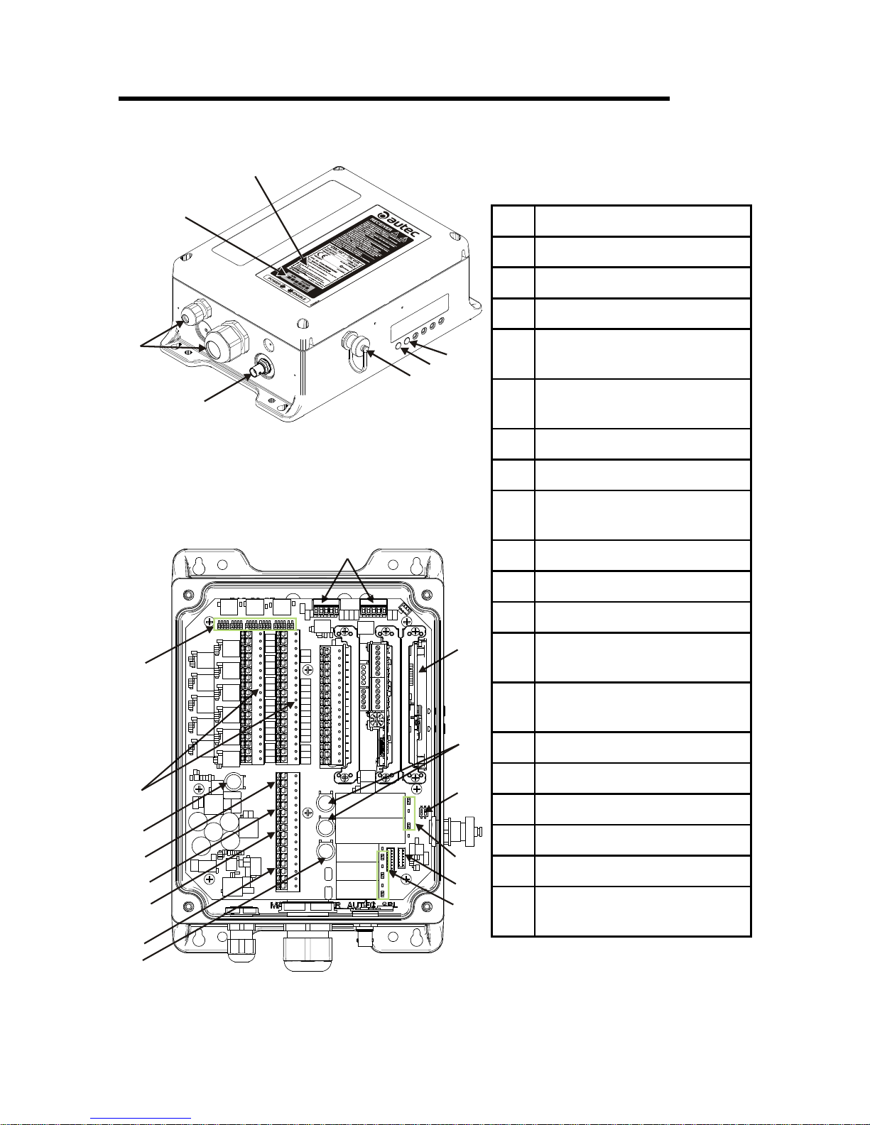
1 Description
A
B
F
G
E
C
D
H
J
K
L
N
P
S
T
Q
R
U
V
M
M
M
A Identication plate
B Technical data plate
C ENABLE LED
D POWER LED
E
Connector for cable control
(optional)
F
BNC connector for external
antenna kit (optional)
G Cable gland or plug
H Digital inputs
J
Electronic module and address
key
K STOP contacts protection fuses
L DIP switches
M Internal light signals
N
Connector for the cable
control's wiring
P
SAFETY contacts protection
fuse
Q Outputs of relay commands
R SAFETY output
S STOP outputs
T Connectors for power supply
U Power supply protection fuse
V
Outputs of solid state
commands

AUTEC - Air series
Technical data 3
LIRMGE00-01
2 Technical data
Power supply ........................................................................................... 12-24V (1.2A)
Power supply protection fuse ....................................................... 3.15A T 250V (5x20mm)
Digital inputs voltage .......................................................................................... 12-24V
Antenna ............................................................................................. internal or dedicated
STOP contacts rated current ........................................................................... 6A (30V )
STOP contacts protection fuses ....................................................... 6A T 250V (5x20mm)
SAFETY contacts rated current ..................................................................... 10A (30V )
SAFETY contacts protection fuses ................................................. 10A T 250V (5x20mm)
Rated current of outputs of solid state commands ........................................... 4A (30V )
Rated current of relay commands' outputsa .................................................. 10A (30V )
b
Housing material .......................................................................................... PA 6 (20%fg)
Protection degree ....................................................................................... IP65 (NEMA 4)
Weight ........................................................................................................... 2.2kg (4.9Lb)
a. Command contacts' rated current for any optional card is provided in the technical data sheet.
b. The rated current may be up to 10A only if both terminals are used for each contact. If the radio
remote control has been wired by Autec, please refer to values provided in the technical data
sheet.
253mm (9.96in)
283mm (11.14in)
252.5mm (9.94in)
287mm (11.3in)
116mm (4.57in)
148mm (5.83in)
185mm (7.28in)
105mm (4.13in)
¿¿=¿¿¿¿
235mm (9.25in)
 Loading...