

Page 1
Benutzerhandbuch / manual / manuale / manuel
Benutzerhandbuch / manual / manuale / manuel
VILLA / VILLA BACK
Page 2
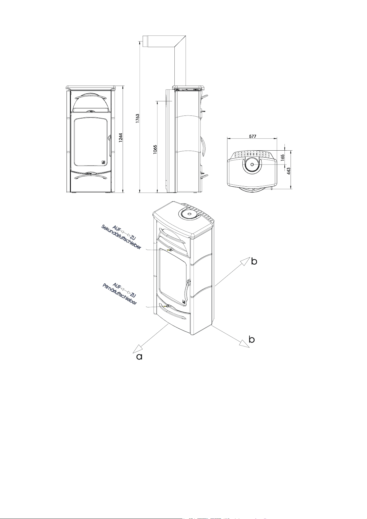
Fig. 1
Fig. 2
deutsch english italiano français
AUF – ZU open – closed aperto – chiuso ouvert - fermé
Sekundärluftschieber secondary air supply Regolazione aria secondaria Coulisseau d’entrée d’air second.
Primärluftschieber primary air supply Regolazione aria primaria Coulisseau d’entrée d’air primaire
deutsch english italiano français
Inhalt Contents Indice sommaire
1. Techn. Daten 1 1. Techn. data 5 1. Dati tecnici 9 1. Caractéristiques 13
2. Wichtige Informationen 1 2. Important information 5 2. Informazioni importanti 9 2. Infos importantes 13
3. So bedienen Sie Ihren 3. Correct operation 3. Per un uso corretto della 3. Bien utiliser votre
Kaminofen richtig 2 of your stove 6 vostra Kaminofen 10 poêle 14
4. Die wichtigsten 4. The most important 4. Prospetto dei ricambi 4. Principales pièces
Ersatzteile - Übersicht 3 spare parts - overview 7 principali 11 détachées 15
5. Ausstattungsmerkmale 4 5.
Garantie 17 Guarantee 17 Garanzia 18 Garantie 18
Equipment characteristics 8 5. Caratteristiche di dotazione 12 5. Attributs 16
Page 3
Villa / Villa Back 1 deutsch
g
g
g
1. TECHNISCHE DATEN
Als Kaminofen der Bauart 1 ist ein Anschluß an
einen bereits mit anderen Öfen und Herden für feste
und flüssige Brennstoffe belegten Schornstein
möglich, sofern die Schornsteinbemessung gemäß
DIN 4705, Teil 3, dem nicht widerspricht.
TECHNISCHE DATEN
Höhe 1224 mm
Breite 577 mm
Tiefe 443 mm
Gewicht 200 k
Gewicht mit Keramikmantel 220 k
Rauchrohrabgang Durchmesser 130 mm
Nennwärmeleistung lt. DIN 18891 8 kW
Maximale Heizleistung 11 kW
Kleinste Heizleistun
Raumheizvermögen (abhängig
von der Hausisolierung)
Abgaswerte für die Mehrfachbelegung des Schornsteines nach DIN 4705, Teil 3 bzw. zur Bemessung
des Schornsteines nach DIN 4705, Teil 2
Abgasmassenstrom geschlossen 8,0 g/s
Abgastemperatur geschlossen 265 °C
Mindestförderdruck bei
Nennwärmeleistung (Nwl)
bei 0,8facher
geschlossen 0,11 mbar
Nwl
4 kW
90 – 180
m³
0,1 mbar
2. WICHTIGE INFORMATIONEN
Die Informationen in diesem Handbuch sind
allgemeiner Natur. Vorschriften können von Land
zu Land unterschiedlich sein; regionale
Vorschriften können Vorrang haben.
Allgemeine Sicherheitshinweise
zum Betrieb Ihres Kaminofens
• Lesen Sie vor der Inbetriebnahme des Ofens
das gesamte Handbuch gründlich durch und
beachten Sie die Warnhinweise.
• Für den Transport Ihres Heizgerätes dürfen
nur zugelassene Transporthilfen mit ausreichender
Tragfähigkeit verwendet werden.
• Ihr Heizgerät ist nicht zur Verwendung als
Leiter oder Standgerüst geeignet.
• Durch den Abbrand von Brennmaterial wird
Wärmeenergie frei, die zu einer starken Erhitzung
der Oberfläche des Heizgerätes, der Türen, der
Tür- und Bediengriffe, der Türgläser, der
Rauchrohre und gegebenenfalls der Frontwand
des Heizgerätes führt. Die Berührung dieser Teile
ohne entsprechende Schutzbekleidung oder
Hilfsmittel wie z.B. Hitzeschutzhandschuhe oder
Betätigungsmittel (kalte Hand), ist zu unterlassen.
• Machen Sie Ihre Kinder auf diese besondere
Gefahr aufmerksam und halten Sie sie während
des Heizbetriebes vom Heizgerät fern.
• Verbrennen Sie ausschließlich das im Kapitel
„saubere Verbrennung“ angeführte genehmigte
Heizmaterial.
• Das Verbrennen oder Einbringen von leicht
brennbaren oder explosiven Stoffen, wie leere
Spraydosen und dgl. in den Brennraum, sowie
deren Lagerung in unmittelbarer Nähe Ihres
Heizgerätes, ist wegen Explosionsgefahr
strengstens verboten.
• Beim Nachheizen sollen keine weiten, oder
leicht brennbaren Kleidungsstücke getragen
werden.
• Das Abstellen von nicht hitzebeständigen
Gegenständen auf dem Heizgerät oder in dessen
Nähe ist verboten.
• Legen Sie keine Wäschestücke zum
Trocknen auf den Ofen.
• Ständer zum Trocknen von Kleidungsstücken
oder dgl. müssen in ausreichendem Abstand vom
Heizgerät aufgestellt werden - Brandgefahr.
• Beim Betrieb Ihres Heizgerätes ist das
Verarbeiten von leicht brennbaren und explosiven
Stoffen im selben oder in anschließenden Räumen
verboten.
Kaminofenaufstellung
Sicherheitsabstände(Mindestabstände)
Fig. 2
1. Zu nicht brennbaren Gegenständen:
a > 400 mm b > 100 mm
2. Zu brennbaren Gegenständen und zu
tragenden Wänden aus Stahlbeton:
a > 800 mm b > 200 mm
(a - nach vorne im Strahlungsbereich)
(b - seitlich und hinten)
Bitte beachten Sie, daß der Aufstellungsraum
mind. eine Türe / ein Fenster ins Freie aufweisen
oder mit einem derartigen Raum direkt verbunden
sein muß.
Technische und optische Änderungen, Satz- und Druckfehler vorbehalten.
Page 4
deutsch 2 Villa / Villa Back
Bodentragfähigkeit
Prüfen Sie vor dem Aufstellen ob die Tragfähigkeit
der Unterkonstruktion dem Gewicht Ihres
Kaminofen standhält.
Rauchrohranschluß
Für den Anschluß der Rauchrohre an den
Schornstein gibt es zu Ihrer eigenen Sicherheit
strenge Richtlinien. Ihr Kaminofen-Fachhändler
kennt diese. Beauftragen Sie daher unbedingt
Ihren Fachhändler mit dem Rauchrohranschluß.
3. SO BEDIENEN SIE IHREN KAMINOFEN RICHTIG
Die erste Inbetriebnahme Ihres
Kaminofens
Ihr Kaminofen wurde mit einem
umweltverträglichen Speziallack lackiert. Die
Lackoberfläche ist bei Auslieferung Ihres Ofen
noch weich. Die Aushärtung des Lacks erfolgt bei
der ersten Inbetriebnahme. Die Lackoberfläche
darf während dieses Vorganges nicht berührt
werden. Der Kaminofen muß mindestens 1,5
Stunden stark aufgeheizt werden. Bei der
Aushärtung des Lackes können sichtbare Dämpfe
freiwerden. Öffnen Sie daher vor der ersten
Inbetriebnahme die Fenster. Dadurch können die
Dämpfe schnell abziehen.
BITTE BERÜCKSICHTIGEN SIE:
mehreren Heizvorgängen ist der Betrieb Ihres
Kaminofen nur mehr vom heimeligen Geruch des
verbrennenden Holzes geprägt.
Erst nach
Zugelassene Brennstoffe
Trockenes, gut abgelagertes, naturbelassenes
Holz, Holzbriketts, Braunkohlebriketts.
Maximale Brennstoffmenge
Max. Brennstoffmenge 1,8 kg 1.7 kg
Primärluft Zu Auf
Sekundärluft ½ auf ¼ auf
Größere Brennstoffmengen können zu
Überhitzung und Beschädigungen am Ofen führen!
Scheitholz Braunkohle-
brikett
Saubere Verbrennung
Das Brennholz muß trocken (rel. Holzfeuchte < 15
%) und unbehandelt sein und die richtige
Brennholzmenge muß verbrannt werden, um eine
saubere, emissionsarme Verbrennung zu
erreichen.
Richtig Feuer machen
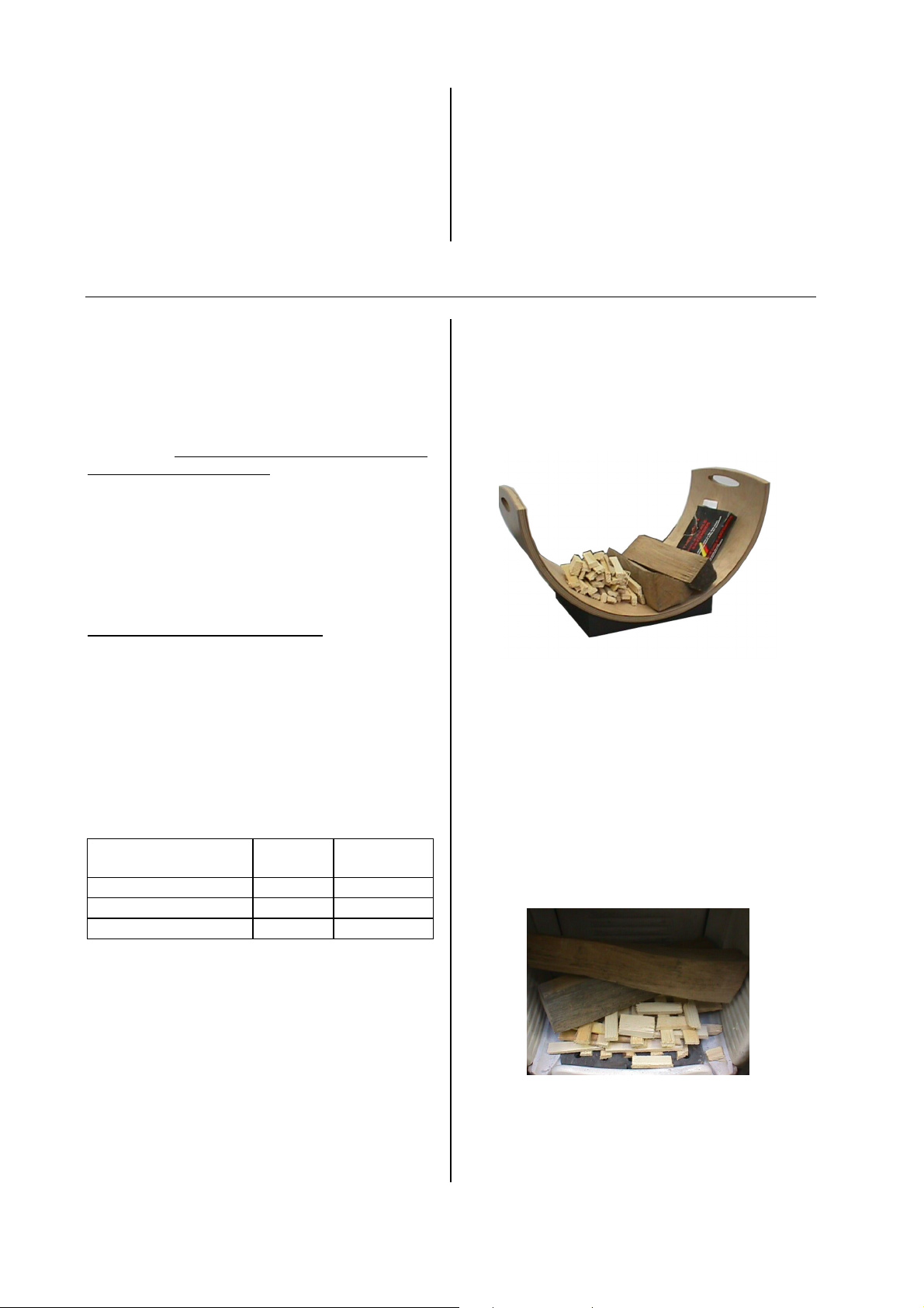
Bereiten Sie alles zum Anheizen vor –
Weichholzspäne, Anzündhilfe (wie zB Thermohit
Holz-Kohleanzünder), unbeschichtetes Papier,
Brennholz. Fig. 3 gibt Ihnen eine Richtlinie
hinsichtlich der Menge an Heizmaterial.
Fig. 3: Heizmaterial
Öffnen Sie die Primär- und Sekundärluftzufuhr
maximal. Bewegen Sie dazu beide Schieber siehe
Fig. 2 „AUF“.
Öffnen Sie die Kaminofentür.
Legen Sie unbeschichtetes Papier auf den
Feuerraumboden.
Legen Sie darauf eine handvoll Weichholzspäne.
Legen Sie auf diese Späne 1 – 2 Scheite Holz.
Fig. 4: Anzünden
Zünden Sie nun das Papier an.
Schließen Sie die Feuerraumtür.
Sobald die Weichholzspäne gut brennen,
schließen Sie den Primärluftschieber.
Symbolabbildungen
Page 5
Villa / Villa Back 3 deutsch
Sobald die Holzscheite gut brennen, können Sie
mit dem Sekundärluftschieber die Heizleistung
regulieren (Schieber auf Maximalstellung „AUF“ =
maximale Heizleistung – siehe Fig. 2).
Beim Nachlegen gehen Sie prinzipiell wie beim
Anheizen vor: Primärluftschieber öffnen,
Sekundärluftschieber öffnen, Kamintüre vorsichtig
öffnen, Holz nachlegen, Kaminofentüre schließen.
Warten Sie, bis das nachgelegte Holz brennt.
Dann schließen Sie den Primärluftschieber. Regeln
Sie in der Folge die Heizleistung mit dem
Sekundärluftschieber.
Fig. 5: Primärluftschieber schließen
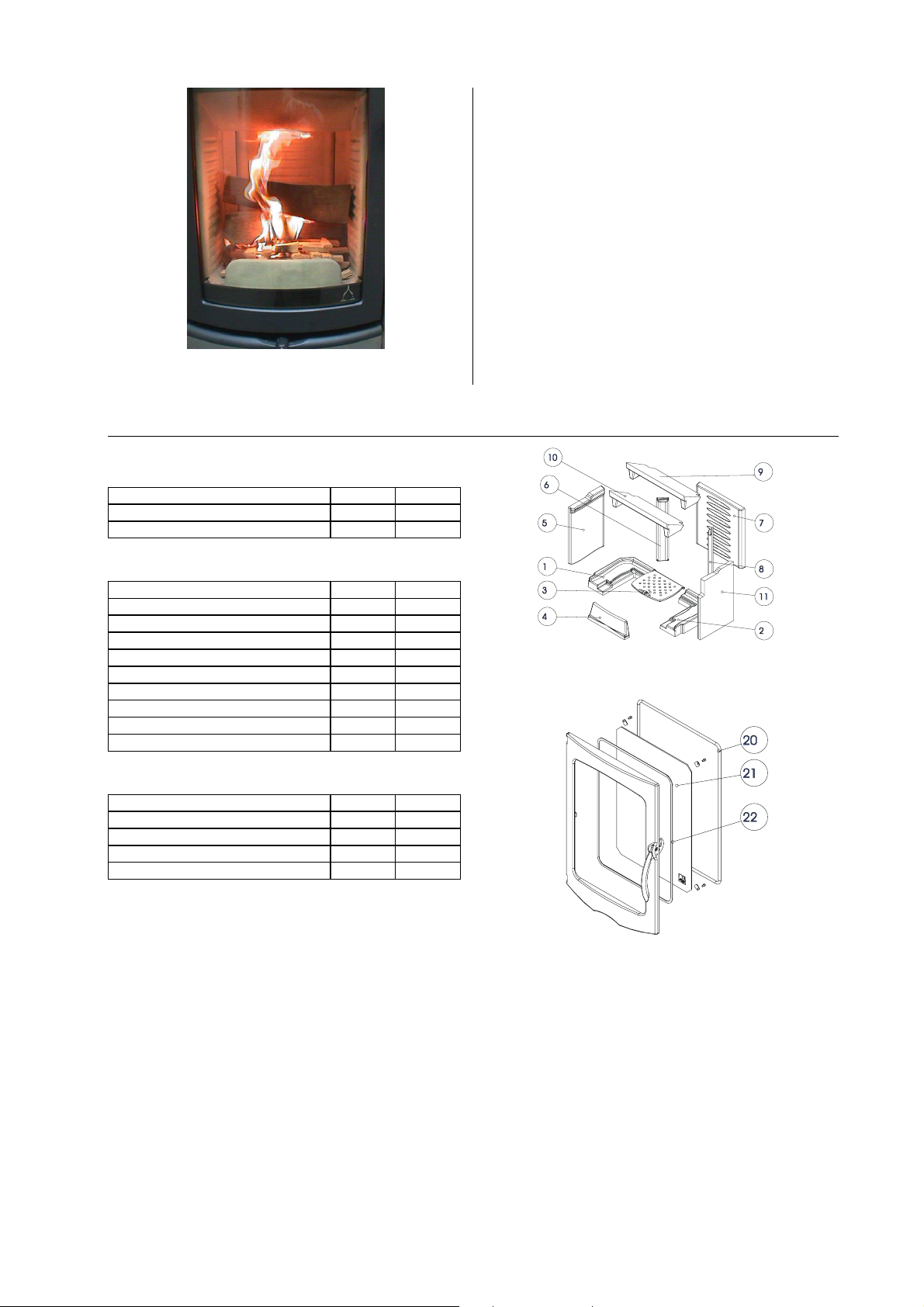
4. DIE WICHTIGSTEN ERSATZTEILE - ÜBERSICHT
Dichtungen
Bezeichnung Nr.-Skizze Artikelnr.
Dichtung flach 8 x 2 mm L=2000 22 710096
Dichtung rund 10 mm L=2200 20 710319
Keramott
Bezeichnung Nr.-Skizze Artikelnr.
Keramott Boden links 1 716823
Keramott Boden rechts 2 716820
G4 Rost 3 716408-27
Keramott Holzfänger 4 716776
Keramott Seitenteil links 5 716804
Keramott Rückwand 7 716821
Keramott Umlenkplatte 9/10 716822
Keramott Eckstein 6/8 716928
Keramott Seitenteil rechts 11 716927
Sonstiges
Bezeichnung Nr.-Skizze Artikelnr.
Villa Türglas 21 716723
Ofenlack -- 650002
Holz-Kohleanzünder -- 640067
Glasreiniger 0,5l -- 640070
Zubehör
Bei Ihrem Fachhändler erhalten Sie Bodenplatten aus Glas oder Stahl, Kaminbestecke oder Pflegemittel.
WICHTIG: Lassen Sie defekte Teile ausschließlich von Ihrem Kaminofenfachhändler austauschen.
Damit ist gewährleistet, daß Ihr Kaminofen sicher und funktionstüchtig ist und bleibt.
Pflege
Zur Glasreinigung verwenden Sie bitte ein Spezialprodukt wie Thermohit Glasreiniger. Lackierte
Oberflächen dürfen nur mit einem Tuch (ev. feucht) gereinigt werden. Für Edelstahloberflächen gibt es
ebenfalls Spezialreiniger.
Numerierung Keramott = Einbauanleitung!
Page 6
Villa / Villa Back 4 deutsch
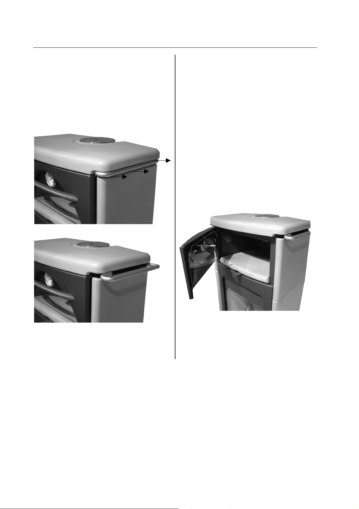
5. Ausstattungsmerkmale Villa / Villa Back
Hängeauszug
Villa / Villa Back verfügen über Hängeauszüge
links und rechts unterhalb der Deckelplatte. Diese
können herausgezogen und Gegenstände daran
aufgehängt werden.
Achtung: Wenn der Ofen in Betrieb ist, keine
brennbaren Gegenstände an den Hängeauszügen
aufhängen!
Holzlagerfach
Unterhalb des Feuerraums befindet sich eine
Holzlage, die mittels des Griffes herausgezogen
werden kann.
Backfach
Das Modell Villa Back unterscheidet sich vom
Modell Villa durch sein voll funktionstüchtiges
Backfach.
Dieses Backfach wird von 3 Seiten beheizt (links,
rechts, hinten). Tip: Um einen möglichst
gleichmäßigen Garvorgang zu erreichen, sollten
Sie das Gargut nach der halben Garzeit drehen.
Die Temperatur im Backfach regulieren Sie über
die aufgegebene Holzmenge und die Luftschieber
(s. o.). Die aktuelle Temperatur können Sie auf
dem Backfachthermometer ablesen.
Fig. 6: Hängeauszug
Fig. 7: Hängeauszug ausgezogen
Fig. 8: Blick ins Backfach
Den Backfachinnenraum reinigen Sie wie andere
Ofenteile auch (s. o.). Vermeiden Sie fetthaltige
Dämpfe, da diese nur sehr schwer zu beseitigende
Verschmutzungen zur Folge haben.
Page 7

Villa / Villa Back 5 english
g
g
1. TECHNICAL DATA
As a stove of construction type 1, it is possible to
connect it to the flue pipe of an existing other stove
or another furnace for solid and liquid fuels, as
long as the chimney does complies with DIN 4705,
Part 3.
TECHNICAL DATA
Height 1224 mm
Width 577 mm
Depth 443 mm
Weight 200 k
Weight with ceramic shell 220 k
Flue pipe outlet diameter 130 mm
Nominal thermal output (DIN 18891) 8 kW
Maximum thermal capacity 11 kW
Smallest heating capacity 4 kW
Room heating capacity (depending on
building insulation)
Exhaust values for multiple use of the chimney in
accordance with DIN 4705, Part 3 and for the
calculation of the chimney measurements in
accordance with DIN 4705, Part 2
Fluegas mass flow closed 8,0 g/s
Fluegas temperature closed 265 °C
Minimum feed pressure
Nominal thermal output
at 0.8 times
closed 0,11 mbar
n. ther. outp.
90 – 180
m³
0,1 mbar
2. IMPORTANT INFORMATION
The installation and operation information given
here is of a general nature, exact regulations may
vary from country to country. The rules in force in
your country should always take precedence.
General Safety Instructions for
the Operation of Your Stove
• Thoroughly read the entire manual before
starting up your stove and ensure compliance with
the warnings.
• Your heating unit may not be moved without
approved means of transport with sufficient loadbearing capacity.
• Your heating unit is not suitable to be used as
a stand or as a ladder.
• The burning of fuel releases thermal energy
that leads to a substantial heating up of the surface
of the heating unit, the doors, the parts mounted
on the door, door glass, flue pipe and in some
cases the front wall of the heating unit. Do not
touch any of these surfaces without respective
protective clothing or without the help of
accessories such as heat-resistant gloves or a cold
hand.
• Make your children aware of this particular
danger and keep them at a distance from the
heating unit whenever it is in operation.
• Only burn approved fuels and materials listed
in the section entitled Clean Burning.
• The burning or introduction of flammable or
explosive materials, such as empty spray cans and
the like into the firebox as well as the storage of
such materials in the immediate vicinity of your
heating unit is strictly forbidden due the danger of
explosion.
• Do not wear loose or flammable clothing when
adding fuel to the fire.
• Placing non-heat-resistant objects on the
heating unit or in the vicinity of the heating unit is
forbidden.
• Do not lay laundry onto the stove for drying.
• Laundry hung up to dry must be kept at a safe
distance from the stove because of the danger of
fire.
• When operating your heating unit it is
forbidden to use flammable or explosive materials
in the same or an adjacent room to the one in
which your heating unit is located.
Setting Up Your Stove
Safety Clearances (Minimum Distances in
Fig. 2; according to DIN)
3. To nonflammable objects:
a > 400 mm b > 100 mm
4. To flammable objects and to supporting walls of
reinforced-concrete construction with
convection shell:
a > 800 mm b > 200 mm
(a – toward the front in the radiated area)
(b – to the side and to the back)
Make sure that the room in which the stove is set
up has at least one door or window to the outside
or is directly adjacent to such a room.
Subject to technical and optical modifications. Formatting and printing errors excepted.
Page 8

english 6 Villa / Villa Back
Floor Load Capacity
Before the heating unit is installed, make sure that
the load capacity of the supporting construction is
sufficient to carry the weight of the entire unit.
Stovepipe Connection
For your own safety stringent laws apply to the
connecting of the stovepipe to the chimney. Your
professional dealer or distributor knows these laws.
Please have your certified retailer carry out the
connection of your stove.
3. CORRECT OPERATION OF YOUR STOVE
Initial startup of your stove
Your stove was treated with a special
environmentally friendly lacquer. The lacquer
surface is still soft at the time the stove is shipped.
The lacquer will harden when your stove is used
for the first time. The lacquer surface may not be
touched when it is heated for the first time. The
stove must be initially heated to a high temperature
for at least 1.5 hours. Visible vapors may appear
during the hardening of the lacquer. For this
reason it will be necessary to open windows during
initial operation in order let the vapors escape into
the outdoors.
PLEASE TAKE NOTE:
sessions before for your stove releases only the
pleasant smell of burning wood.
It takes several heating
Approved Fuels
Dry, well cured and natural wood, wood briquettes,
brown-coal briquettes.
Maximum Amount of Fuel
max. amount of fuel 1,8 kg 1.7 kg
primary air closed open
secondary air ½ open ¼ open
Larger amounts of fuel can lead to overheating and
thus damage the stove.
Wood
logs
Wood
briquettes
Clean Burning
The wood must be dry (relative wood moisture <
15%) and untreated and the right amount of wood
must be burned in order to ensure a clean fire that
releases only small amounts of emissions.
Making a Fire
Prepare everything you need for starting the fire—
soft wood chips, igniter materials (such as
Thermohit wood/coal igniter), uncoated paper,
wood. Figure 1 provides a good overview of the
materials you will need.
Figure 3: Heating Material
Open the primary and secondary air all the way.
Move both sliders. See Figure 2.
Open the stove door.
Lay uncoated paper on the floor of the firebox.
Lay soft wood chips onto the paper.
Lay one or two logs of wood on the wood chips.
Figure 4: Igniting the Fire
Light the paper.
Close the firebox.
As soon as the chips are burning well, close the
primary air supply.
symbol figures
Page 9

Villa / Villa Back 7 english
As soon as the wood logs are burning well, you
can regulate the heating capacity with the
secondary air slider. (Slider set to the maximum
(“AUF”) setting produces maximum heat – see
Figure 2.)
When adding wood to the fire, follow the same
procedure as when igniting the fire: Open primary
air, open secondary air, carefully open firebox
door, lay wood on the fire, close the firebox door.
Wait until the added wood catches fire and is
burning. Then close the primary air. Subsequently
regulate the fire with the secondary air supply.
Figure 5: Close the Primary Air
4. THE MOST IMPORTANT SPARES—OVERVIEW
Gaskets
Description Nr. drawing Part number
Flat gasket 8 x 2 mm 22 710096
Round gasket 12 mm 20 710319
Keramott
Description Nr. drawing Part number
bottom left, keramott 1 716823
bottom right, keramott 2 716820
grate 3 716408-27
wood retainer, keramott 4 716776
side component left, kermott 5 716804
rear, keramott 7 716821
baffle plate, keramott 9/10 716822
cornerstone left/right, keramott 6/8 716928
side component right, keramott 11 716927
Other parts
Description Nr. drawing Part number
Villa glass 21 716723
Stove lacquer -- 650002
Wood/coal igniter -- 640067
Glass cleaner ½ litre -- 640070
Accessories
You can obtain floor plates of glass or steel, fireplace utensils or care products from your certified dealer.
IMPORTANT: Have defective parts replaced by your certified dealer. This will guarantee that your
stove functions properly and safely.
Maintenance
To clean the glass, please use a specialized product such as Thermohit glass cleaner. Lacquered
surfaces are to be cleaned only with a cloth (may be damp). Special cleaning agents should also be used
for stainless steel surfaces.
Keramott numbering = installation instructions!
Page 10

Villa / Villa Back 8 english
5. Villa / Villa Back equipment characteristics
Towel rails
Villa / Villa Back have towel rails located to the left
and right under the cover plate. These can be
pulled out to hang towels, etc. on them.
Warning: when the stove is in use, do not hang
flammable objects on the towel rails!
Fig. 6: Towel rail
Wood compartment
The wood store is located underneath the stove, it
can be opened by pulling on the handle.
Baking compartment
The Villa Back model differs from the Villa model in
that it has a fully functional baking compartment
This oven is heated on three sides (left, right,
back). Tip: to achieve the best cooking results, turn
the food being cooked around half-way through the
cooking time.
The temperature in the oven is controlled by the
amount of wood used and the air vent (see above).
The actual temperature is displayed on the oven
thermometer.
Fig. 7: Extended towel rail
Fig. 8: View inside oven
Clean the interior of the oven in the same way as
the other stove components (see above). Avoid
greasy vapors as these will lead to contamination
that is very hard to remove.
Page 11

Villa / Villa Back 9 italiano
g
g
1. DATI TECNICI
Questa stufa-caminetto (Kaminofen del tipo Bauart
1) è adatta per essere collegata ad una canna
fumaria già utilizzata per altre stufe o fonti di calore
che impiegano combustibili solidi o liquidi, se le
dimensioni della canna fumaria lo consentono
(norma DIN 4705, Parte 3).
DATI TECNICI
Altezza
Larghezza
Profondità
Peso
Peso con rivestimento in ceramica
Diametro uscita fumi
Rendimento nominale (secondo DIN 18891)
Rendimento massimo
1224 mm
577 mm
443 mm
200 k
220 k
130 mm
8 kW
11 kW
Rendimento minimo
Volume riscaldabile (dipende dalle
coibentazioni)
4 kW
90 – 180
m³
Valori delle emissioni per allacciamento multiplo alla canna
fumaria (secondo norma DIN 4705, Parte 3) e per il calcolo
delle dimensioni della canna fumaria (secondo DIN 4705, Parte
2)
Flusso fumi chiuso
Temperatura fumi chiuso
Depressione minima con
rendimento nominale (r.nom.)
Con potenza calorifica
nominale di 0,8 volte
chiuso
con r.nom. di
0,8 volte
8,0 g/s
265 °C
0,11 mbar
0,1 mbar
2. INFORMAZIONI IMPORTANTI
Questo manuale contiene informazioni generali. Le
normative possono cambiare da paese a paese; le
normative locali possono risultare prioritarie.
Avvertenze generali e precauzioni
nell'impiego della Kaminofen
• Prima di mettere in funzione la stufa vi
raccomandiamo di leggere attentamente l'intero
manuale che vi fornisce importanti informazioni e
avvertimenti.
• Per il trasporto della stufa utilizzate mezzi
idonei, la cui portata sia sufficiente a sostenerne il
peso.
• Non utilizzate la stufa come se fosse una
scala o un'impalcatura per salirvi sopra.
• In seguito alla combustione si libera energia
termica, che provoca un forte riscaldamento della
superficie della stufa e del tubo uscita fumi. Fate
attenzione quindi ed evitate di toccare componenti
come l'antina, la maniglia, le leve di regolazione
delle prese d'aria, il vetro ceramico, il tubo di uscita
fumi ed eventualmente la parte frontale della stufa
senza una protezione adeguata, ad esempio un
guanto o altri utensili (gancio smuovicenere,
”manofredda”).
• Istruite i vostri bambini su questi inconvenienti
e teneteli lontani dalla stufa quando è accesa.
• Utilizzate solo i combustibili indicati nel
capitolo „Combustibili adatti“.
• Nella camera di combustione non devono
essere introdotte e bruciate sostanze facilmente
infiammabili od esplosive, come bombolette spray
vuote e simili. Non lasciate tali oggetti nelle
immediate vicinanze della stufa (pericolo di
esplosione).
• Quando si aggiunge legna nella stufa accesa
è consigliabile non portare capi di abbigliamento
che possano prendere fuoco facilmente.
• Non appoggiate oggetti non resistenti al
calore sulla stufa o nelle sue immediate vicinanze.
• Non mettete ad asciugare biancheria sopra la
stufa.
• Stendibiancheria o simili devono essere
collocati ad una distanza adeguata dalla stufa
(pericolo di incendio).
• Quando la stufa è in funzione è sconsigliabile
lavorare con sostanze facilmente infiammabili o
esplosive nella stessa stanza o in stanze adiacenti.
Installazione della stufa
Distanze di sicurezza (distanze minime)
Fig. 2
1. Da oggetti non infiammabili:
a > 400 mm b > 100 mm
2. Da oggetti infiammabili e pareti portanti in cemento
armato:
a > 800 mm b > 200 mm
(a - anteriormente nell’area di irradiazione)
(b - lateralmente e posteriormente)
Il luogo in cui installate la stufa deve disporre di
almeno una porta / finestra che dia all’esterno
oppure deve essere collegato direttamente ad un
ambiente con accesso all’esterno.
Salvo modifiche di carattere tecnico ed estetico o errori di fotocomposizione e stampa.
Page 12

italiano 10 Villa / Villa Back
Portata del pavimento
Prima di installare la stufa, accertatevi che la
struttura sottostante al punto in cui volete
sistemarla sia in grado di sopportarne il peso.
Collegamento del tubo di uscita
fumi
Per garantire la vostra sicurezza, il collegamento
dei tubi di uscita fumi alla canna fumaria è regolato
da apposite norme. Per l’installazione e il
collegamento rivolgetevi quindi al vostro
rivenditore, che è a conoscenza di tali disposizioni.
3. PER UN USO CORRETTO DELLA VOSTRA
KAMINOFEN
Quando mettete in funzione la
stufa per la prima volta
La vostra Kaminofen è stata rifinita con una
speciale vernice ecocompatibile. Al momento della
fornitura le superfici laccate e verniciate non sono
ancora completamente indurite. L'indurimento
definitivo avviene con il calore che si sviluppa
durante la prima accensione. Durante questa
fase, che deve durare almeno 1,5 ore e a calore
intenso, non toccate le superfici della stufa e
arieggiate bene l'abitazione, per eliminare
rapidamente eventuali odori e vapori causati
dall'indurimento della vernice.
VI PREGHIAMO DI TENERE CONTO DEL
FATTO CHE solo dopo aver acceso la stufa varie
volte per un periodo continuato, avvertirete il
caratteristico (e piacevole) odore della legna che
arde.
Combustibili adatti
Legna naturale e non trattata, secca e ben
conservata, tronchetti di legno pressato e
mattonelle di lignite.
Quantità massime di combustibili
quantità massime di combustibili
l’aria primaria ciuso aperto
l’aria secondaria ½ aperto ¼ aperto
Non introducete quantità eccessive di combustibile
per evitare un surriscaldamento ed un
conseguente danneggiamento della stufa.
legna
naturale
1,8 kg 1.7 kg
legno
pressato
Combustione ed ecologia
Per ottenere una combustione corretta con un
minimo di emissioni la legna deve essere secca (<
15 % di umidità relativa) e non trattata e non si
devono superare le quantità di combustibile
consigliate.
Per una corretta accensione
Preparate tutto l'occorrente per accendere la stufa:
trucioli di legno dolce, accendifuoco (ad es.
Thermohit), carta (non patinata), e legna.
L'illustrazione 1 vi fornisce le indicazioni circa le
giuste quantità per l‘accensione.
lIl. 1 : Materiali per l'accensione
Aprite al massimo la presa per l'aria primaria e
quella per l’aria secondaria, spostando le due
levette come indicato nella fig. 2 “AUF / aperto”.
Aprite ora l'antina.
Disponete dapprima della carta (non patinata) sul
fondo della camera di combustione, sopra di essa
una manciata di trucioli di legno dolce e poi 1 o 2
ceppi di legna.
lIl. 2 : Accensione
Dopo aver dato fuoco alla carta, chiudete l'antina e
attendete fino a quando i trucioli stanno bruciando
per poi chiudere la presa dell'aria primaria.
Spiegazione dei simboli
Page 13

Villa / Villa Back 11 italiano
Quando anche i ceppi avranno incominciato a
prendere ben fuoco, potete regolare il rendimento
della stufa con la levetta dell'aria secondaria
(portandola nella posizione massima otterrete il
massimo del rendimento).
Questa operazione va ripetuta per ogni strato di
legna che vorrete aggiungere: aprite la presa
dell'aria primaria e quella dell'aria secondaria, poi
l'antina (facendo attenzione), aggiungete la legna e
richiudete infine l'antina. Attendete fino a quando
anche la nuova legna abbia preso ben fuoco e poi
chiudete nuovamente la presa dell'aria primaria,
regolando infine il rendimento con la levetta
dell'aria secondaria.
lIl.3 : Chiusura presa dell'aria primaria
4. PROSPETTO DEI RICAMBI PRINCIPALI
Guarnizioni
Denominazione N. su dis. N. art.
Guarnizione piatta 8x2 mm 22 710096
Guarnizione tonda 12 mm 20 710319
Keramott
Denominazione N. su dis. N. art.
keramott di fondo sinistra 1 716823
keramott di fondo destra 2 716820
griglia 3 716408-27
keramott fermalegna 4 716776
keramott lateral sinistra 5 716804
keramott posteriore 7 716821
keramott tagliafiamme 9/10 716822
keramott angolare sinistro / destro 6/8 716928
keramott lateral destra 11 716927
Altre parti
Denominazione N. su dis. N. art.
Vetroceramico antina Villa 21 716723
Vernice -- 650002
Accendifuoco -- 640067
Detergente vetroceramico 0,5 l -- 640070
Accessori
Presso il vostro rivenditore potete acquistare basi di protezione in vetro o acciaio, vari utensili per la stufa
ed anche prodotti per la cura e pulizia.
IMPORTANTE: per la sostituzione di parti difettose rivolgetevi esclusivamene al vostro rivenditore di
Kaminofen, in questo modo avrete la garanzia che la vostra stufa continuerà a funzionare in modo
corretto e sicuro.
Pulizia
Per la pulizia del vetro ceramico dell'antina utilizzate gli appositi prodotti in vendita presso i rivenditori di
stufe (ad es. Thermohit). Le superfici laccate della stufa vanno pulite solamente con un panno
(eventualmente umido). Anche le superfici in acciaio inox vanno trattate con gli appositi detergenti.
Numerazione dei refrattari = ordine da seguire per il
montaggio!
Page 14

Villa / Villa Back 12 italiano
5. Caratteristiche di dotazione Villa / Villa Back
Corrimano estraibile
Villa e Villa Back sono dotate di pratici corrimano
estraibili su ambedue i lati della stufa, proprio sotto
la piastra di copertura, per appendervi vari oggetti
ed accessori.
Attenzione: non appendervi oggetti infiammabili
quando la stufa è in funzione!
Fig. 6: Corrimano laterale inserito
Cassetto portalegna
Il comodo cassetto per la legna, facilmente
estraibile per mezzo di una maniglia, è collocato
proprio sotto la camera di combustione.
Piano forno
Il modello Villa Back si arricchisce, rispetto a quello
Villa, di un pratico ed efficiente forno di cottura.
Il piano forno viene riscaldato da 3 lati (sinistro,
destro e posteriore). Suggerimento: per ottenere
una cottura possibilmente omogenea è utile girare
le pietanze una volta trascorsa la metà del tempo
di cottura.
La temperatura all’interno del piano forno è
regolabile sia con la quantità di legna caricata, sia
tramite i registri dell’aria (v. sopra). Il termometro
incorporato rileva continuamente la temperatura
interna.
Fig. 7: Corrimano laterale estratto
Fig. 8: Vista del vano forno
La pulizia dell’interno del piano forno è facile come
quella di qualsiasi altra parte della stufa (v. sopra).
Si consiglia comunque di evitare vapori grassi che
potrebbero provocare incrostazioni molto
difficilmente da eliminare.
Page 15

Villa / Villa Back 13 français
g
g
1. CARACTÉRISTIQUES TECHNIQUES
En tant que poêle de type 1, il peut être raccordé à
un conduit de cheminée déjà occupé par d’autres
poêles ou cuisinières à combustibles solides et
liquides, à condition toutefois que les dimensions
du conduit de cheminée ne contredisent pas la
norme DIN 4705 Partie 3.
CARACTÉRISTIQUES TECHNIQUES
Hauteur 1224 mm
Largeur 577 mm
Profondeur 443 mm
Poids 200 k
Poids avec habillage céramique 220 k
Diamètre sortie tuyau raccordement 130 mm
Puissance calorifique nominale selon
DIN 18891
Puissance calorifique maximale 11 kW
Puissance calorifique minimale 4 kW
8 kW
Volume chauffé (selon
l’isolation du bâtiment)
Caractéristiques des gaz de combustion en vue de
l’installation de plusieurs appareils sur un conduit
de cheminée selon DIN 4705 Partie 3 ou du
dimensionnement du conduit de cheminée selon
DIN 4705 Partie 2
Débit de gaz de
combustion
Température des gaz
de combustion
Pression d’extraction
minimale à la puissance
nominale
fermé 8,0 g/s
fermé 265 °C
fermé 0,11 mbar
à 0,8 fois la
puissance
nominale
90 – 180
m³
0,1 mbar
2. INFORMATIONS IMPORTANTES
Les informations dans ce manuel sont générales.
Effectivement les règlements peuvent varier de
pays en pays et les règlements régionaux peuvent
être prioritaires.
Remarques générales concernant
la sécurité
• Lisez attentivement l’ensemble du manuel
avant de mettre le poêle en service et
respectez les avertissements relatifs à la
sécurité.
• Le transport de l’appareil doit toujours être
effectué au moyen d’un appareillage
autorisé et de capacité suffisante.
• Le poêle ne doit pas être utilisé comme
échelle ou comme marchepied.
• La combustion libère de l’énergie
thermique qui entraîne un fort
échauffement de la surface de l’appareil,
des portes, des poignées, des vitres des
portes, des tuyaux de raccordement et
parfois de la face avant de l’appareil. Ne
touchez ces éléments qu’avec une
protection adéquate, par exemple des
gants isolants ou un instrument
d’actionnement.
• Expliquez bien le risque de brûlures à vos
enfants et tenez-les éloignés de l’appareil
lorsque celui-ci fonctionne.
• Utilisez toujours un combustible autorisé
selon le chapitre «Combustion non
polluante».
• La combustion ou l’introduction de
matières très inflammables ou explosives
Installation du poêle
Distances de sécurité minimales
(Fig. 2)
1. Par rapport à des objets non inflammables :
2. Par rapport à des objets inflammables et aux
dans le foyer, par exemple de bombes
aérosols vides, est strictement interdite en
raison du risque d’explosion, de même que
la conservation de tels produits à proximité
de l’appareil.
• Ne rechargez pas le poêle alors que vous
portez des vêtements amples ou en
matières inflammables.
• Il est interdit de déposer des objets ne
résistant pas à la chaleur sur l’appareil ou
à proximité.
• Ne faites pas sécher de linge sur le poêle.
• Les étendages et égouttoirs à linge ou
autres doivent être placés suffisamment
loin de l’appareil pour éviter tout risque
d’incendie.
• Lorsque le poêle est en marche, ne
travaillez jamais avec des matières
facilement inflammables ou explosives
dans le local où il se trouve ni dans une
pièce adjacente.
a > 400 mm b > 100 mm
murs porteurs en béton armé :
a > 800 mm b > 200 mm
(a : sur l’avant dans la zone de rayonnement)
(b : sur les côtés et l’arrière)
Sous réserve de modifications techniques et optiques, ainsi que d'erreurs de composition et d'impression.
Page 16

français 14 Villa / Villa Back
Attention : le local dans lequel vous installez le
poêle doit être pourvu au minimum d’une porte ou
d’une fenêtre donnant à l’extérieur, ou
communiquer avec une autre pièce donnant à
l’extérieur.
Capacité portante du sol
Avant d’installer l’appareil, vérifiez si le sol pourra
en supporter le poids.
Raccordement du tuyau
Pour votre sécurité, des consignes strictes doivent
être respectées pour le raccordement du tuyau au
conduit de cheminée. Votre installateur
professionnel connaît bien ces règles. Il faut donc
impérativement confier à ce professionnel le
raccordement du tuyau.
3. POUR BIEN UTILISER VOTRE POÊLE
Première mise en service
Votre poêle a été peint avec un vernis spécial non
polluant. Cet enduit est encore mou lors de la
livraison. Il ne durcit que lors de la première mise
en service. En attendant, ne touchez pas la
surface peinte. Laissez le poêle chauffer fortement
pendant au moins 1 heure 1/2. Le vernis peut
dégager des vapeurs visibles pendant qu’il durcit.
Il faut donc ouvrir les fenêtres avant la première
mise en service, afin d’évacuer rapidement ces
vapeurs.
ATTENTION :
votre poêle pour qu’il ne sente plus que l’odeur
habituelle du bois qui brûle.
Il faut faire chauffer plusieurs fois
Combustibles autorisés
Bois naturel sec et bien conservé, briquettes de
bois ou de lignite.
Quantité maximale de
combustible
Qté. maxi.combustibles 1,8 kg 1.7 kg
Air primaire fermé ouvert
Air secondaire ½ ouvert ¼ ouvert
N’utilisez pas plus de combustible, sous peine de
provoquer une surchauffe qui endommagera le
poêle.
Bûches
de bois
Briquettes
de lignite
Combustion non polluante
Le bois doit être sec (humidité relative < 15 %) et
non traité. Il doit être utilisé en quantité adéquate
pour obtenir une combustion propre et dégageant
peu d’émissions.
Pour bien faire du feu
Préparez tout ce dont vous avez besoin pour
allumer le poêle : copeaux de bois tendre, allumefeu, papier non enduit, bois de chauffage. La
Figure 3 indique la bonne quantité de matériaux à
disposer dans le foyer.
Fig. 3 : Matériaux combustibles
Ouvrez au maximum les arrivées d’entrée d’air
primaires et secondaires, en déplaçant les deux
coulisseaux (voir la Figure 2).
Ouvrez la porte du poêle.
Déposez du papier (non enduit) sur le fond du
foyer. Déposez par-dessus une poignée de
copeaux puis 1 ou 2 bûches.
Fig. 4 : Allumage
Allumez le papier.
Fermez la porte du foyer.
Dès que les copeaux brûlent bien, fermez le
coulisseau d’entrée d’air primaire.
Représentation des symboles
Page 17

Villa / Villa Back 15 français
Dès que les bûches brûlent bien, réglez la
puissance de chauffage avec le coulisseau
d’entrée d’air secondaire (position maximale du
coulisseau = puissance maximale).
Pour recharger le poêle, suivez la même séquence
que pour l’allumage : ouvrez les coulisseaux
d’entrée d’air primaire puis d’entrée d’air
secondaire, ouvrez prudemment la pote du poêle,
ajoutez du bois et refermez la porte.
Attendez que le bois ajouté s’enflamme, puis
refermez le coulisseau d’entrée d’air primaire.
Réglez la puissance de chauffage avec le
coulisseau d’entrée d’air secondaire.
Fig. 5 : Fermeture du coulisseau d’entrée d’air
primaire
4. PRINCIPALES PIÈCES DÉTACHÉES
Joints
Désignation N° sur schéma Réf. article
Joint plat 8 x 2 mm L=2000 22 710096
Joint rond 10 mm L=2200 20 710319
Céramique réfractaire
Désignation N° sur schéma Réf. article
Keramott en bas à gauche 1 716823
Keramott en bas à droite 2 716820
Grille en bas G4 3 716408-27
Keramott pare-bûche 4 716776
Keramott côté gauche 5 716804
Keramott au centre 7 716821
Keramott déflecteur 9/10 716822
Keramott angle g/d 6/8 716928
Keramott côte droit 11 716927
Autres
Désignation N° sur schéma Réf. article
Vitre porte Villa 21 716723
Vernis pour poêle -- 650002
Allume-feu bois et charbon -- 640067
Nettoyant pour vitres 0,5 l -- 640070
Accessoires
Vous trouverez chez votre revendeur spécialisé des plaques de fond en verre ou en métal, des
instruments de cheminée et des produits d’entretien.
IMPORTANT : Les pièces défectueuses doivent toujours être remplacées par votre revendeur
spécialisé, afin que le poêle reste sûr et en bon état de marche.
Entretien
Pour le nettoyage des vitres, utilisez un produit spécial tel que le Thermohit. Les surfaces peintes doivent
être nettoyées avec un chiffon (ev. Humide). Pour le nettoyage des surfaces en acier inoxydable, il existe
également un produit spécial.
Numérotation des céramiques réfractaires =
instructions de montage !
Page 18

Villa / Villa Back 16 français
5. Attributs Villa / Villa Back
Tringle escamotable
Villa / Villa Back est équipé de tringles
escamotables par coulissement situées à gauche
et à droite en dessous de la plaque formant
couvercle. On peut sortir celles-ci pour y
suspendre des objets.
Attention: Ne pas suspendre d’objets inflammables
aux tringles lorsque le four est allumé !
Compartiment bois
Un tiroir à bois, que l’on peut ouvrir en tirant sur la
poignée, est situé en dessous du foyer.
Compartiment à four
Le modèle Villa Back se distingue du modèle Villa
par son compartiment à four tout à fait fonctionnel.
Ce compartiment à four est chauffé sur 3 côtés (à
gauche, à droite et à l’arrière). Un conseil : pour
une cuisson uniforme, vous devriez tourner ce que
vous être en train de cuire en milieu de cuisson.
La température dans le compartiment à four est
réglée par la quantité de bois utilisée et par le
registre d’admission d’air (voir ci-dessus). La
température actuelle est affichée sur le
thermomètre du compartiment à four.
Fig. 6: Tringle escamotable
Fig. 7: Tringle escamotable sortie
Fig. 8: Vue de l’intérieur du compartiment cuisson
Pour nettoyer l’intérieur du compartiment à four,
vous procédez comme pour les autres parties du
four (voir ci-dessus). Evitez les vapeurs grasses ;
l’encrassement qu’elles provoquent est très difficile
à éliminer.
Page 19

GARANTIE / GUARANTEE / GARANZIA / GARANTIE
2 Jahre Garantie
Für Ihren AUSTROFLAMM-Kaminofen garantieren
wir für die einwandfreie Funktion aller Bauteile aus
Stahl und Guß 2 Jahre ab dem Erstverkaufsdatum.
Stahl- und Gußteile, die während der Garantiezeit
Material- und / oder Verarbeitungsmängel
aufweisen, werden gegen Neuteile ersetzt.
Wir gewähren keine Garantie auf Verschleißteile
(z. B.: Keramott, Dichtungen, Bodenrost),
Oberflächenbeschichtungen, Lack, Glas und
Keramiken.
Voraussetzungen für unsere Garantieleistung sind
1. Ihr AUSTROFLAMM-Kaminofen wurde gemäß
dem Benutzerhandbuch betrieben und von
einem Fachmann installiert.
2. Der Garantieanspruch wird mit der vollständig
ausgefüllten Garantiekarte und der Rechnung
bei einem AUSTROFLAMM-Fachhändler
geltend gemacht.
WICHTIG: Unsere Garantieleistung umfaßt die
kostenlose Lieferung der Neuteile. Arbeits- und
Wegzeiten werden dadurch nicht umfaßt. Eine
ungerechtfertigte Garantieinanspruchnahme wird
dem Betreiber rückbelastet.
---------------------------------------------------------------------------------------------------------------------------------------
Im Garantiefall herausschneiden und Ihrem AUSTROFLAMM-Fachhändler vorlegen!
In the event of claims to the guarantee, separate here and present this proof of purchase to your certified AUSTROFLAMM dealer.
GARANTIE / GUARANTEE / GARANZIA / GARANTIE
Two-Year Guarantee
We guarantee full functionality of all
AUSTROFLAMM stove components made of steel
or cast iron for a full two years from the date of
purchase. Steel and cast-iron components which
show defect in materials or workmanship during
the guarantee period shall be replaced with new
components.
We do not guarantee wearable components (such
as Keramott, gaskets, floor grid), surface coatings,
lacquer, glass and ceramics.
Conditions of the Guarantee
:
1. Your AUSTROFLAMM stove was installed by
a certified professional and is operated in
accordance with the operator’s manual.
2. Claims to the guarantee shall be subject to a
completely filled-out Guarantee Card and
submittal of the original invoice issued by a
certified AUSTROFLAMM sales agent.
IMPORTANT: Our guarantee includes free
shipping of new components. Work and travel
times are not included. Unwarranted claims shall
be re-invoiced to the operator.
:
Händlerstempel / Dealer’s Stamp / Timbro concessionario /
tampon du concessionnaire
angeschlossen von / Installed by / installato da / raccordée par
Kaufdatum / date of purchase / Data d’acquisto / date
d’achat
Modellname / Name of Model / tipo del modello / nom du
produit
V I L L A
Serien No. / serial no. / No. di serie / no. de série
(siehe Typenschild / See manufacturer’s plate /
Vedi targhetta / voir plaque signalétique)
Page 20

r
GARANTIE / GUARANTEE / GARANZIA / GARANTIE
2 anni di garanzia
Noi garantiamo il buon funzionamento di tutti i
componenti in acciaio e ghisa della vostra
Kaminofen AUSTROFLAMM per una durata di 2
anni a partire dalla data della prima vendita. Le
parti in acciaio e ghisa che dovessero presentare
difetti di materiale e/o lavorazione durante il
periodo di garanzia verranno sostituite con parti
nuove.
Sono escluse dalla garanzia le parti soggette ad
usura (ad es. elementi in keramott, guarnizioni,
griglie della camera di combustione), nonché i
rivestimenti delle superfici, vernici, vetroceramico
ed elementi in ceramica.
Per avere diritto alle prestazioni di garanzia
1. La vostra Kaminofen AUSTROFLAMM deve
essere installata da personale specializzato e
fatta funzionare osservando le istruzioni del
manuale.
2. Occorre presentare la cartolina di garanzia
correttamente compilata e lo scontrino / la
fattura / la ricevuta fiscale ad uno dei
rivenditori AUSTROFLAMM.
IMPORTANTE: la nostra Garanzia copre la
fornitura gratuita delle parti nuove e non include
né la durata dell'intervento né la trasferta. I costi
collegati ad una richiesta ingiustificata di
prestazione di garanzia saranno addebitati
all'utente.
-------------------------------------------------------------------------------------------------------------------------------------
In caso di richiesta di garanzia, ritagliare la cartolina e presentarla al rivenditore AUSTROFLAMM!
Découpez selon les pointillés et présentez ce coupon à votre revendeur AUSTROFLAMM.
:
Garantie 2 ans
Nous garantissons le bon fonctionnement de tous
les éléments en acier et en fonte des poêles
AUSTROFLAMM pendant 2 ans à compter de la
date du premier achat. Les pièces en acier et en
fonte présentant un défaut de matériau et/ou de
fabrication pendant la durée de la garantie seront
remplacées par des pièces neuves.
Nous déclinons toute garantie pour les pièces
d’usure (par ex. céramique réfractaire, joints, grille
de fond), les joints de surfaces, le vernis, les vitres
et les céramiques.
Conditions d’application de la garantie :
1. Votre poêle AUSTROFLAMM doit avoir été
installé par un spécialiste et utilisé
conformément au mode d’emploi.
2. La demande de garantie doit être présentée à
un revendeur spécialisé AUSTROFLAMM en
même temps que la carte de garantie
complétée et que la facture.
IMPORTANT : Notre service sous garantie
couvre le remplacement gratuit par des pièces
neuves. Les temps de travail et de déplacement
ne sont pas inclus. En cas de demande abusive
d’application de la garantie, nous présenterons à
l’utilisateur une facture correspondante.
Austroflamm GmbH, Gfereth 101, 4631 Krenglbach, Austria, Stand 08/02
GARANTIE / GUARANTEE / GARANZIA / GARANTIE
Kunde / Customer / cliente / client
an/ to / per / pour
Marke
Stamp
Francobollo
affranchi
 Loading...