

Page 1
MANUALE D’USO BEDIENUNGSANLEITUNG
OWNER’S MANUAL MODE D’EMPLOI
Amplificatore di potenza per auto
Auto Hi Fi Endstufen
Car power amplifier
Amplificateur de puissance pour l’automobile
Power measures taken according to audison standard 1998 edition.
- 12 VDC and 13.8 VDC.
- 1 kHz or crossover cut-off frequency.
- 0.3 % THD nominal power; 1% THD continuous power.
- Tolerance: +10 %; -5 %.
- Continuous power given by RMS Voltage measured on resistive load.
- The nominal power of the amplifier is measured upon a battery voltage of 12 Volts
with a 4 Ohms load and with all channels in function.
PRINTED IN ITALY - Code 10123901
62018 Potenza Picena (MC) Italy
Tel. 0733.870.870 • Fax 0733.870.880 • http://www.audison.com
is a division of
Page 2

2 19
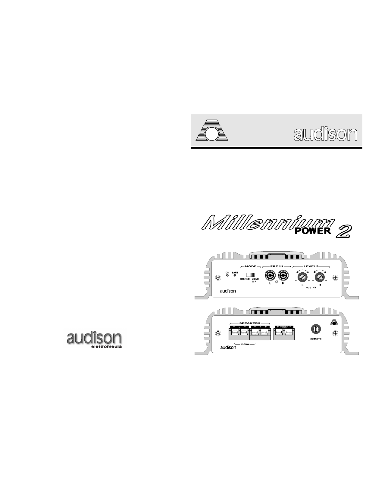
MILLENNIUM POWER 2 (MP2): CARATTERISTICHE
MP2
. Amplificatore a due canali di dimensioni compatte e dalle elevate caratteristiche musicali. I
tratti fondamentali della sofisticata circuitazione sono: stadi "FRONT END" realizzati con due stadi
differenziali complementari, stadi finali costituiti da transistors in connessione Darlington, transistors
finali con capacità in corrente pari a 15 A ed alimentatore PWM a MOSFET dall'elevata riserva di
energia. Il dimensionamento progettuale consente un agevole funzionamento su carichi nominali di
2 Ohm nella configurazione stereo e 4 Ohm nella configurazione mono a ponte. Queste
caratteristiche consentono una notevole versatilità di utilizzo sia nel pilotaggio di sistemi multivia, sia
nel collegamento in mono di SUBWOOFERS nella configurazione TRI - MODE.
PRECAUZIONI
· Per un buon funzionamento dell'apparecchio è importante accertarsi che la temperatura nel luogo
dove esso è installato sia compresa tra 0°C e 55°C.
· Il luogo prescelto per l'installazione deve essere ben ventilato ed asciutto.
· La tensione di alimentazione è di 12 VCC con negativo a massa. Accertarsi che le caratteristiche
dell'impianto elettrico del veicolo siano adatte per questo apparecchio.
· Per una maggiore sicurezza di guida si consiglia l'ascolto ad un livello tale da non coprire i suoni
provenienti dall'esterno dell'auto.
INSTALLAZIONE
Il fissaggio si effettua mediante il serraggio nelle apposite sedi delle 4 viti e relativi distanziali in
dotazione.
Per un'ottima riuscita dell'impianto si consiglia di usare i prodotti della linea audison cable che
comprendono: cavi di alimentazione, di segnale, per altoparlanti, connettori RCA e tutti gli accessori
per il completamento del cablaggio.
AVVERTENZE
· INGRESSI: Nell'eventualità che il radioriproduttore non avesse in comune la massa di uscita con il
telaio si dovrà collegare la calza del cavo schermato con il telaio del radioriproduttore.
· USCITE: Non collegare in alcun caso tra loro oppure a massa le uscite -R e -L. Nel caso si utilizzi un
filtro crossover accertarsi che esso non abbia la massa in comune tra i canali.
· REGOLAZIONI: Nel caso si udissero fenomeni di saturazione a livelli di volume non elevato,
significa che il segnale esce distorto dal radioriproduttore. Portare il controllo di volume del
radioriproduttore verso un livello più basso fino alla scomparsa della distorsione. Regolare
successivamente i livelli di taratura dell'amplificatore fino ad udire lievi fenomeni di saturazione.
Page 3
318
MILLENNIUM POWER 2 (MP2): FEATURES
MP2. Two-channel amplifier with compact dimensions and excellent musical performances.
The outstanding features of their sophisticated circuitry are: "FRONT END" stages realized by two
complementary differential stages, final stages made of transistors in Darlington connection, final
transistors with current capacity of 15 A and MOSFET PWM power supply with a high energy
reserve.
Their design allows their easy functioning on 2 Ohms nominal loads in stereo configuration and 4
Ohms nominal loads in bridge mono configuration.
These features allow a great use versatility both in driving multiway systems and in SUBWOOFER
mono connection in TRI-MODE configuration.
PRECAUTIONS
· In order for this device to function properly it's important that it is installed in a spot where
temperature doesn't fall below 0° C (32° F) or rise above 55° C (131° F).
· It must be installed in a dry and well ventilated spot.
· Power supply voltage is 12 VCC with negative to ground. Make sure that the characteristics of the
vehicle electrical system are compatible with this device.
· For safe driving we advise to listen to music at a volume level that won't drown external traffic
sounds.
INSTALLATION
For mounting use 4 self-threading screws and protective plastic rings provided. For a very good
result we suggest to use audison cable products to complete your installation. These include:
power cables, signal cables, speaker wires, RCA connectors and all accessories needed to complete
the wiring.
WARNINGS
· INPUTS: If the radio-cassette player doesn't share the output GND with the chassis, the braided
shield of the shielded cable must be connected to the radio-cassette player chassis.
· OUTPUTS: Never connect -R and -L outputs to ground or to each other. If a crossover filter is
used, be sure its two channels don't have a common ground.
· REGULATIONS: If you hear saturation phenomena at moderate volume levels, it means that a
distorted signal is coming from the radio-cassette player.
Turn radio-cassette player volume down until there's no longer any distortion.
Then adjust the amplifier calibration levels until you hear slight saturation phenomena.
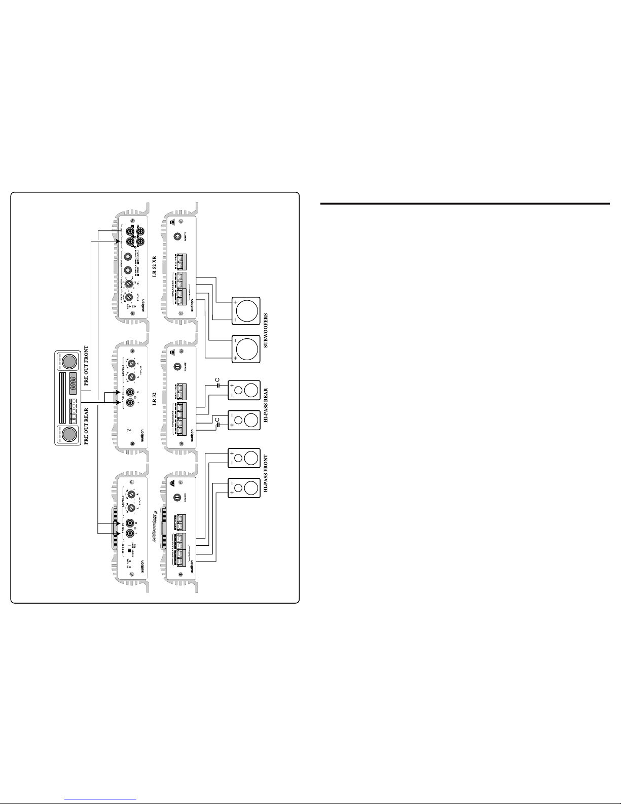
FRONT, SUBWOOFER AND PASSIVE HI-PASS REAR WITH FADER
Page 4

4
MILLENNIUM POWER 2 (MP2):
CARACTÉRISTIQUES
MP2
. Ampli à deux canaux de dimensions compactes et à hautes caractéristiques musicales.
Les éléments fondamentaux de leur circuit sophistiqué sont: stades "FRONT END" réalisés avec deux
stades différentiels complémentaires, stades finals constitués de transistors en connexion Darlington,
transistors finals chacun avec capacité en courant de 15 A et alimentation PWM à MOSFET avec une
grande réserve d'énergie.
Leur projet permet un fonctionnement facile sur charges nominales de 2 Ohm pour ce qui concerne
la configuration stéréo et de 4 Ohm pour la configuration mono en pont.
Ces caractéristiques permettent une grande souplesse d'utilisation, soit pour le pilotage des systèmes
multivoies, soit pour la connexion avec des SUBWOOFER en mono ou en TRI-MODE.
PRÉCAUTIONS
· Pour un bon fonctionnement de l'appareil, il très important de veiller à l'installer dans un endroit où
la température ne tombe jamais au dessous de 0°C et ne dépasse jamais 55°C.
· L'installation doit se faire dans un endroit sec et bien ventilé.
· L'alimentation est de type 12 VCC avec négatif à la masse. S'assurer que les caractéristiques de
l'installation du véhicule soient indiquées pour ce type d'appareil.
· Pour une conduite sans risque, nous conseillons un niveau d'écoute ne couvrant pas le bruit du
trafic environnant.
INSTALLATION
Pour le montage utiliser les rondelles et vis fournies à cet effet. Pour un résultat optimum il est
recommandé d'utiliser les éléments de la ligne audison cable suivants: câbles d'alimentation,
câbles signal, câbles pour haut-parleurs, connecteurs RCA et tous les accessoires complétant le
branchement.
ATTENTION
· ENTRÉES: Si la masse de sortie de l'auto-radio n'est pas la même que celle du châssis, relier le fil
du câble isolant au châssis de l'auto-radio.
· SORTIES: Ne jamais connecter entre elles ou sur la masse les sorties -R et -L. Avant d'utiliser un
filtre crossover, s'assurer que les canaux n'ont pas de masse commune.
· RÉGLAGES: Si des phénomènes de saturation apparaissent à un niveau de volume modéré, cela
signifie que le signal sort distordu de l'auto-radio.
En ce cas, abaisser le volume de l'autoradio jusqu'à ce que le phénomène disparaisse et régler
ensuite les niveaux de l'amplificateur.
17
FRONT, SUBWOOFER AND FREQUENCY VARIABLE REAR WITH EXTERNAL
ELECTRONIC CROSSOVER
Page 5

MILLENNIUM POWER 2 (MP2):
EIGENSCHAFTEN
MP2. Zweikanal-Verstärker mit kompakten Abmessungen und exzellenten musikalischen
Fähigkeiten. Die außergewönlichen Eigenschaften ihrer hochwertigen Schaltkreise sind:
Eingansstufen mit zwei komplementären Differenzverstärkern, Endstufen mit Transistoren in
Darlington-Bauweise, Endtransistoren mit einer Strombelastbarkeit von 15A und ein MOSFETSchaltnetzteil mit hoher Energiereserve. Ihre Auslegung erlaubt einen problemlosen Betrieb an zwei
Ohm in der Stereo-Konfiguration und an vier Ohm in gebrückter Mono-Konfiguration. Diese
Ausstattungen erlauben eine große Anwendungsbreite angefangen von Mehrwege-Systemen bis
hin zu TRI MODE-Konfigurationen mit Mono-Subwoofer.
Vorsichtsmassnahmen
· Damit das Gerät ordnungsgemäß arbeiten kann, muß es an einem Einbauort montiert werden,
bei dem die Temperatur nicht unter 0° C sinkt und über 55° C steigt.
· Es muß an einem trockenen, gut belüfteten Ort eingebaut werden.
· Es muß an eine 12-Volt-Versorgungsspannung mit Minus an Masse angeschlossen werden.
Stellen Sie sicher, daß die Netzspannung Ihres Fahrzeugs dies Voraussetzungen erfüllt.
· Damit beim Fahren die Sicherheit nicht zu kurz kommt, empfehlen wir, den Hörpegel auf einen
Betrag zu begrenzen, der es noch zuläßt, die Verkehrsgeräusche außerhalb des Fahrzeugs
wahrzunehmen.
INSTALLATION
Beim Einbau sollten Sie die 4 beigelegten selbstschneidenden Schrauben und Plastik-Schutzringe
benutzen. Wenn Sie eine besonders hohe Klangqualität erreichen wollen, empfehlen wir, die
Verbindungskabel von audison cable zu verwenden. Im audison cable-Programm sind verfügbar:
Stromversorgungskabel, Cinchkabel, Lautsprecherkabel, Cinch-Stecker und -Buchsen sowie alle
Zubehörteile, die Sie benötigen, um die Verkabelung durchzuführen.
WARNUNGEN
· EINGÄNGE: Wenn die Ausgangs-Masse des Autoradios nicht an die Fahrzeugmasse
angeschlossen ist, muß das Abschirmgeflecht des Cinch-Verbindungskabels mit dem Gehäuse des
Radios verbunden werden.
· AUSGÄNGE: Verbinden Sie die Lautsprecher-Ausgänge niemals mit Masse oder miteinander.
Wenn Sie ein Lautsprechersystem mit vorgeschalteter Frequenzweiche verwenden, stellen Sie sicher,
daß die Weiche keine gemeinsame Masse für beide Kanäle aufweist.
· EINSTELLUNGEN:Wenn Sie bei moderaten Lautstärken Verzerrungen wahrnehmen, ist mit
Sicherheit der Eingang des Verstärkers übersteuert. Drehen Sie den "Low Pass"-Regler ganz nach
links. Drehen Sie dann den Lautstärkeregler des Radios etwa auf
3/4 des Maximums. Nun regeln sie am "Low Pass" die Lautstärke, bis leichte Verzerrungen hörbar
werden. Vorsicht! Sie sollten diese Einstellungen zügig vornehmen, da hohe Lautstärken entstehen.
516
FRONT, SUBWOOFER AND FREQUENCY VARIABLE REAR WITH FADER
Page 6

6 15
HI-PASS AND SUBWOOFER ACTIVE SYSTEM
FRONT, REAR AND SUBWOOFER ACTIVE SYSTEM
Page 7

MP2
7
BLOCK DIAGRAM
14
TRI MODE SYSTEM WITH FADER
TRI MODE CONNECTION
LOUDSPEAKERS IMPEDANCE
4 Ohms 8 Ohms
L (mH) C (µF) L (mH) C (µF)
FREQUENCY
Hertz
60
80
100
120
150
200
10.6
7.9
6.4
5.3
4.3
3.2
660
495
400
330
265
200
21.0
15.9
12.7
10.6
8.5
6.4
330
245
200
165
132
100
HI-PASS
HI-PASS
SUBWOOFER
Page 8

8
ENGLISH
TECHNICAL DATA
POWER SUPPLY 11 ÷ 15 VDC
IDLING CURRENT 1 A
MAX CONSUMPTION (Nominal Pwr) 24 A
MAX DYNAMIC POWER (2 Ch x 4 Ohms) 135 W
MAX DYNAMIC POWER (1 Ch x 4 Ohms) Bridge 405 W
CONT. NOMINAL POWER (Tol. +10%; -5%)
2 Ch x 4 Ohms; 0.3% THD; 12 VDC 95 W (RMS)
CONT. OUT POWER (2 Ch x 4 Ohms; 13.8 VDC) 100 W (RMS)
CONT. OUT POWER (2 Ch x 2 Ohms; 13.8 VDC) 150 W (RMS)
MONO OUT POWER (1 Ch x 4 Ohms; 13.8 VDC) Bridge 300 W (RMS)
DISTORTION THD (1 KHz; 90% Nominal Pwr) 0.07 %
BANDWIDTH (-3 dB; Nominal Pwr) 4 Hz ÷ 100 KHz
DAMPING FACTOR (4 Ohms) 150
RISE TIME 4.5 µS
SIGNAL / NOISE RATIO 98 dBA
INPUT SENSITIVITY 0.3 V ÷ 4 VRMS
INPUT IMPEDANCE 15 KOhms
LOAD IMPEDANCE Stereo 8 - 4 - 2 Ohms
LOAD IMPEDANCE Mono 8 - 4 Ohms
REMOTE IN 7 ÷ 15 VDC
DIMENSIONS (WxHxD) 175 x 50 x 330 mm (6.88 x 1.96 x 12.99 inch)
ITALIANO
DATI TECNICI
ALIMENTAZIONE 11 ÷ 15 VDC
ASSORBIMENTO A VUOTO 1 A
ASSORBIMENTO MAX (Pot. Nominale) 24 A
MAX DYNAMIC POWER (2 Ch x 4 Ohm) 135 W
MAX DYNAMIC POWER (1 Ch x 4 Ohm) Bridge 405 W
POTENZA NOMINALE CONT. (Toll. +10 %; -5 %)
2 Ch x 4 Ohm; 0,3 % THD; 12 VDC 95 W (RMS)
POTENZA OUT CONTINUA (2 Ch x 4 Ohm; 13,8 VDC) 100 W (RMS)
POTENZA OUT CONTINUA (2 Ch x 2 Ohm; 13,8 VDC) 150 W (RMS)
POTENZA OUT MONO (1 Ch x 4 Ohm; 13,8 VDC) Bridge 300 W (RMS)
DISTORSIONE THD (1 KHz; 90% Pot. Nominale) 0,07 %
BANDA PASSANTE (-3 dB; Pot. Nominale) 4 Hz ÷ 100 KHz
FATTORE DI SMORZAMENTO (4 Ohm) 150
TEMPO DI SALITA 4,5 µS
RAPPORTO SEGNALE RUMORE 98 dBA
SENSIBILITA' D'INGRESSO 0,3 V ÷ 4 VRMS
IMPEDENZA D'INGRESSO 15 KOhm
IMPEDENZA DI CARICO Stereo 8 - 4 - 2 Ohm
IMPEDENZA DI CARICO Mono 8 - 4 Ohm
REMOTE IN 7 ÷ 15 VDC
DIMENSIONI (BxAxL) 175 x 50 x 330 mm
FONCTIONS ET RÉGLAGES
ON
Il indique que l'amplificateur est activé.
INDICATEURS LUMINEUX
ENTRÉES
CHOIX DE LA
FONCTION
RÉGLAGE
DE NIVEAU
PRE IN
Entrées Left et Right de
l'ampli. Elles peuvent
être utilisées pour
amplifier la sortie PRE
d'une source de signal
(radio,CD) ou celle d'un
filtre actif électronique
ou d'un quelconque
modèle de signal à
étage préamplifié.
LEVELS
Réglage de
niveau de la
sortie de
l'ampli. La
sensibilité
varie de 300
mV à 4V.
L/R
Sorties de puissance pour les canaux
Left et Right de l'ampli. Connecter les
hautparleurs selon les polarités
indiquées.
MONO
Sorties pour la configuration mono
en pont. A utiliser quand l'ampli est
positionné sur MONO IN R au
moyen du sélecteur situé sur le
cadran antérieur de l'ampli.
BORNES DE SORTIE
REMOTE
BORNES
D'ALIMENTATION
POWER
Borne d'entrée pour
l'alimentation de
l'amplificateur. Connecter le
positif et le négatif de la
batterie avec les polarités
indiquées. Le voltage doit être
entre 11 et 15 VDC.
IN
Réglage d'activation pour
l'amplificateur provenant de
l'autoradio (ou de toute autre
source avec une sortie pour le
remote des amplificateurs).
Le voltage appliqué doit être
entre 7 et 15 VDC.
13
SAFE
Il indique l'intervention des protections
en cas de surchauffe (max 80° C) ou
anomalies de sortie (présence d'un
courant continu, courtcircuit ou
impédance de charge très basse).
L'intervention des protections rend
l'amplificateur inopérant. Mettre
l'amplificateur en position OFF, éliminer
le problème et remettre en position ON.
MODE
STÉRÉO:
Il sélectionne
l'ampli pour un
fonctionnement
stereo.
MONO:
Il sélectionne
l'ampli pour un
foctionnement
mono. Entrée
utilisée: Right.
DISPOSITION DES BORNES DE CONNECTION
Page 9

9
DEUTSCH
TECHNISCHE DATEN
NETZTEIL 11 ÷ 15 VDC
RUHESTROM 1 A
MAXIMALER STROMVERBRAUCH (bei Nennleistung) 24A
MAX DYNAMIC POWER (2 Kan. je 4 Ohm Last) 135 W
MAX DYNAMIC POWER (1 Kan. je 4 Ohm Last) Bridge 405 W
NENNLEISTUNG (Toleranz +10 %; -5 %)
2 Kanäle je 4 Ohm Last; 0,3 % Klirrfaktor; 12 VDC 95 W (RMS)
DAUER-AUSGANGSLEIST. (2 Kan. je 4 Ohm Last; 13,8 VDC) 100 W (RMS)
DAUER-AUSGANGSLEIST. (2 Kan. je 2 Ohm Last; 13,8 VDC) 150 W (RMS)
MONO-AUSGANGSLEIST. (1 Kan. je 4 Ohm Last; 13,8 VDC) Bridge 300 W (RMS)
KLIRRFAKTOR THD (bei 1 KHz; 90 % Nennleistung) 0,07 %
LEISTUNGSBANDBREITE (-3 dB; Nennleistung) 4 Hz ÷100 KHz
DÄMPFUNGSFAKTOR (4 Ohm) 150
ANSTIEGSZEIT 4,5 µS
STORABSTAND 98 dBA
EINGANGSEMPFINDLICHKEIT 0,3 V ÷ 4 VRMS
EINGANGSIMPEDANZ 15 KOhm
LASTIMPEDANZ Stereo 8 - 4 - 2 Ohm
LASTIMPEDANZ Mono 8 - 4 Ohm
REMOTE IN 7 ÷ 15 VDC
ABMESSUNGEN (BxHxT) 175 x 50 x 330 mm
FRANÇAIS
DONNÉES TECHNIQUES
ALIMENTATION 11 ÷ 15 VDC
CONSOMMATION MIN. 1 A
CONSOMMATION MAX. (Puissance Nominale) 24 A
MAX DYNAMIC POWER (2 Ch x 4 Ohm) 135 W
MAX DYNAMIC POWER (1 Ch x 4 Ohm) Bridge 405 W
PUISSANCE NOMINALE CONTINUE (Toll. +10 %; -5 %)
2 Ch x 4 Ohm; 0,3 % DHT; 12 VDC 95 W (RMS)
PUISSANCE SORTIE CONT. (2 Ch x 4 Ohm; 13,8 VDC) 100 W (RMS)
PUISSANCE SORTIE CONT. (2 Ch x 2 Ohm; 13,8 VDC) 150 W (RMS)
PUISS. SORTIE MONO (1 Ch x 4 Ohm; 13,8 VDC) Bridge 300 W (RMS)
DISTORSION HARM. TOTALE (1 KHz; 90 % Puiss. Nom.) 0,07 %
BANDE PASSANTE (-3 dB; Puiss. Nom.) 4 Hz ÷ 100 KHz
COEFFICIENT D'AMORTISSEMENT (4 Ohm) 150
TEMPS DE MONTÉE 4,5 µS
RAPPORT SIGNAL/BRUIT 98 dBA
SENSIBILITÉ D'ENTRÉE 0,3 V ÷ 4 VRMS
IMPEDANCE D'ENTRÉE 15 KOhm
IMPEDANCE DE CHARGE Stereo 8 - 4 - 2 Ohm
IMPEDANCE DE CHARGE Mono 8 - 4 Ohm
REMOTE IN 7 ÷ 15 VDC
DIMENSIONS (BxHxL) 175 x 50 x 330 mm
SCHALTER UND REGLER
ON
Leuchtet, wenn der Verstärker eingeschaltet ist.
FUNKTIONANZEIGEN
EINGÄNGE
FUNKTIONSWEISE
PEGELREGLER
PRE IN
Linker und rechter
Eingang des Verstärkers.
Hier wird der
Vorverstärker-Ausgang
einer Signalquelle
(Autoradio mit Cassette,
CD oder DAT), einer
Aktivweiche oder jedes
anderen Typs von
Signalprozessor auf
Vorverstärkerpegel
angeschlossen.
LEVELS
Pegelregler für die
LautsprecherAusgänge des
Verstärkers.
Empfindlichkeit
zwischen
300mV und 4V
regelbar.
L/R
Ausgangsklemmen für den linken
und rechten Kanal des Verstärkers.
Verbinden Sie die Lautsprecher
entsprechend der abgebildeten
Polaritäten.
MONO
Ausgangsklemmen für den MonoBrücken-Betrieb. Müssen benutzt
werden, wenn das Gerät mittels
Schalter auf der Frontseite in den
Mono-Modus geschaltet wurde.
AUSGANGSKLEMMEN
REMOTE
STROMVERSORGUNG
POWER
Eingangsklemmen für die
Stromversorgung des
Verstärkers. Verbinden Sie das
Plus-und Massekabel (Minus)
mit den korrespondierenden
Klemmen am Verstärker. Die
angelegte Spannung muß
zwischen 10 und 15 Volt
betragen.
IN
Anschluß für Schaltspannung
zum Einschalten des
Verstärkers, kommt vom
Autoradio (oder von einem
anderen Gerät, das ebenfalls
über eine Schaltspannung für
Verstärker verfügt). Die
Schaltspannung muß zwischen
7 und 15 Volt Gleichspannung
betragen.
SAFE
Leuchtet, wenn die Schutzschaltungen
eingreifen: bei zu hoher Temperatur
(oberhalb 80° C) und Störungen an den
Lautsprecher-Anchlüssen (Gleichstrom,
Kurzschluß, zu niedrige Lastimpedanz). Wenn
die Schutzschaltung eingreift, deaktiviert sich
der Verstärker. Schalten Sie die Anlage aus
und korrigieren Sie den Fehler. Dann können
Sie den Verstärker wieder einschalten.
MODE
STEREO:
Aktiviert den
Stereo-Betrieb.
MONO:
Erlaubt den MonoBetreib des
Verstärkers. Dabei
wird nur der rechte
Eingang benutzt.
ANSCHLUßKONFIGURATION
12
Page 10

1110
COMANDI E FUNZIONI
ON
Indica l'accensione dell'amplificatore.
SEGNALAZIONI LUMINOSE
INGRESSI
PREDISPOSIZ. DI
FUNZIONAMENTO
CONTROLLI
DI LIVELLO
PRE IN
Ingressi Left e Right
dell'amplificatore.
Possono essere utilizzati
per amplificare l'uscita
PRE di una sorgente di
segnale (autoradio,
lettore CD DAT) oppure
l'uscita di un crossover
elettronico o di un
qualunque tipo di
processore di segnale a
livello preamplificato.
LEVELS
Regolazioni
di livello per
l'uscita Left e
Right
dell'amplifica
tore. La
sensibilità
varia da
300mV a 4V.
L/R
Uscite di potenza per i canali Left e
Right dell'amplificatore. Collegare gli
altoparlanti secondo le polarità
indicate.
MONO
Uscite per la configurazione mono a
ponte. Da utilizzare quando
l'amplificatore è selezionato in
modalità MONO IN R per mezzo
dell'apposito selettore posto sulla
placchetta frontale dell'amplificatore.
MORSETTI DI USCITA
REMOTE
MORSETTI DI
ALIMENTAZIONE
POWER
Morsetti di ingresso per
l’alimentazione dell'
amplificatore. Collegare il
positivo ed il negativo di
batteria secondo le polarità
indicate. La tensione applicata
deve essere compresa tra 11 e
15 VDC.
IN
Comando di accensione per
l'amplificatore proveniente
dall'autoradio (o qualunque
tipo di sorgente provvista di
apposita uscita per il comando
di remote per gli
amplificatori). La tensione
applicata deve essere
compresa fra 7 e 15 VDC.
SAFE
Indica l'intervento delle protezioni:
temperatura eccessiva (80°C max) o
anomalie di uscita (presenza di corrente
continua, cortocircuito o impedenza del
carico pericolosamente bassa). L'intervento
della protezione rende inoperativo
l'amplificatore. Spegnere l'amplificatore,
rimuovere la causa dell'anomalia e quindi
riaccendere l'apparecchio.
MODE
STEREO:
Configura
l'amplificatore per
il funzionamento in
stereo.
MONO:
Configura
l'amplificatore in
mono. Ingresso
utilizzato Right.
CONFIGURAZIONE DEI MORSETTI DI COLLEGAMENTO
CONTROLS AND FUNCTIONS
ON
Lit when the amplifier is on.
INDICATORS LIGHTS
INPUTS
FUNCTION
SELECTION
LEVEL
CONTROLS
PRE IN
Left and Right inputs of
the amplifier.
They can be used to
amplify the PRE output
of a signal source
(radio, CD-DAT), an
electronic crossover
output or an output of
any kind of signal
processor at
preamplified level.
LEVELS
Level control
for the
amplifier Left
and Right
outputs.
Sensitivity
varies from
300 mV to
4V.
L/R
Power outputs for the Left and Right
channels of the amplifier. Connect
loudspeakers according to indicated
polarities.
MONO
Outputs for bridge mono
configuration. To be used when the
amplifier is selected in MONO IN R
configuration through the switch on
the front side of the amplifier.
OUTPUT CLAMPS
REMOTE
POWER SUPPLY
CLAMPS
POWER
Input clamps for the amplifier
power supply.
Connect the battery positive
and negative according to
indicated polarities.
Applied voltage must be
between 11 and 15 VDC.
IN
Turn on control for the
amplifier coming from radiocassette player (or from any
sources provided with remote
control for amplifiers).
Applied voltage must be
between 7 and 15 VDC.
SAFE
When lit, it indicates the intervention of
protection circuits: in case of overheating
(temperature exceeding 80° C / 176° F) or
output anomalies (presence of continuous
current, short circuit, or dangerously low
load impedance). When protection circuits
intervene, the amplifier shuts down. Turn
the amplifier off. When the problem is
corrected, turn the amplifier back on.
MODE
STEREO:
The amplifier is
selected as stereo.
MONO:
The amplifier si
selected as mono.
Right input is used.
CONFIGURATION OF CONNECTING CLAMPS
 Loading...