

Page 1
Strada Regina Km 3,5 • I 62018 Potenza Picena (MC) Italy • Tel. +39.0733.870.870 • Fax +39.0733.870.880
http://www.audison.com
PRINTED IN ITALY - Code 10125400
MANUALE D’USO BEDIENUNGSANLEITUNG
OWNER’S MANUAL MODE D’EMPLOI
Amplificatore di potenza per auto
Auto Hi Fi Endstufen
Car power amplifier
Amplificateur de puissance pour l’automobile
LR 605 XR
Power measures taken according to audison standard 1995 edition.
- 12 VDC and 13.8 VDC
- 1 KHz or crossover cut-off frequency
- 0.3 % THD
- Tolerance: +10 %; -5 %
- Continuous power given by RMS Voltage measured on resistive load
- The nominal power of the amplifier is measured upon a battery voltage of
12 Volts with a 4 Ohms load and with all channels in function.
Page 2
ENGLISH
FEATURES
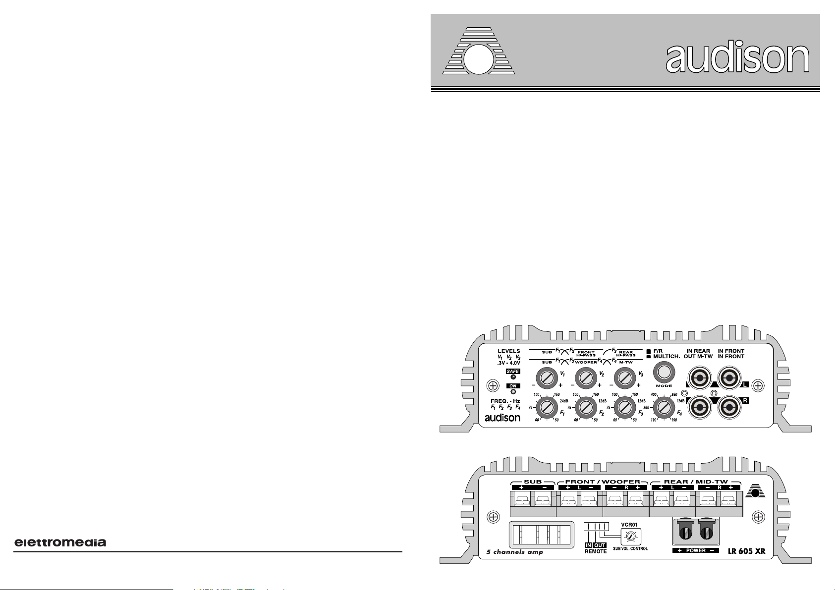
LR 605 XR. It is a five channel amplifier with high musical performances.The outstanding features of its
sophisticated circuitry are : “FRONT END” stages realized by two complementary differential stages,
final stages made of transistors in Darlington connection, final transistors with in current capacity of 15
A and MOSFET PWM power supply with high energy reserve.
This device has four 50 W RMS on 4 Ohms channels and a 200 W RMS on 4 Ohms and 290 W RMS
on 2 Ohms channel, specific for SUBWOOFER.Channels are driven by a sophisticated crossover which
can be configurated at two or three ways through Mode switch; in both configurations, one way, which
has a 24dB slope, is dedicated to the SUBWOOFER, which is also supplied with FADER CONSTANT
BASS function (Subwoofer constant level when Front/Rear level is varied through Fader control).
The crossover has four independent adjustments for cut-off frequencies, three adjustments for output
levels, two preamplified output/input connectors.
Mode: Switch on F/R (Front/Rear).
It allows the realisation of a HI FI, FRONT REAR system. The FRONT section is driven by the IN
FRONT input, which handles a Lo Pass filter (50 Hz - 150 Hz) for SUBWOOFER, and a Hi Pass filter
(50 Hz - 150 Hz); each filter is supplied with a frequency and level control. The REAR section is driven
by IN REAR input, which handles a Hi Pass filter (50 Hz - 150 Hz), equal to the one of the FRONT
section, with its own frequency and level control.
Mode: Switch on MULTICH. (Multichannel).
It allows the realisation of a HI FI, two way FRONT + SUB system. The only input which can be used is
IN FRONT.
It handles a Lo Pass filter (50 Hz - 150 Hz) for SUBWOOFER, a Band Pass filter for WOOFERS
(50 Hz - 150 Hz / 150 Hz - 850 Hz) and a Hi Pass filter for MID-TW (150 Hz - 850 Hz).
The crossover frequencies between SUBWOOFER and WOOFER are handled by two independent
frequency adjusters. Cut-off frequency between WOOFER and MID-TW is controlled by a single adjuster.
Each of the three power outputs is adjusted through its own level control. The Hi Pass section of MID-
TW filter (150 Hz - 850 Hz) is repeated on the proper OUT M-TW preamplified output, and it does not
have a volume adjuster. Output level is 0dB.
Sub remote volume control.
LR 605 XR is designed in order to be used with an accessory kit for the SUB volume remote control.
This accessory is VCR01K and it is supplied separately by audison. VCR01K consist of three parts:
1) Volume control (VCR01);
2) Module to put into LR 605 XR (VCA);
3) Connecting cables between VCR01 and the proper pins on the LR 605 XR power outputs panel.
PRECAUTIONS
In order for this device to function properly it’s important that it is installed in a spot where temperature
doesn’t fall below 0°C (32°F) or rise above 55°C (131°F).
It must be installed in a dry and well ventilated spot.
Power supply voltage is 12 VCC with negative to ground.
Make sure that the caracteristics of the vehicle
electrical system are compatible with this device.
For safe driving we advise to listen to music at a volume level that won’t drown external traffic sounds.
INSTALLATION
For mounting use 4 self-threading screws and protective plastic rings provided. For a very good result
we suggest to use audison cable products to complete your installation. These include: power cables,
signal cables, speaker wires, RCA connectors and all accessories needed to complete the wiring.
WARNINGS
INPUTS: If the radio-cassette player doesn’t share the output GND with the chassis, the braided shield
of the shielded cable must be connected to the radio-cassette player chassis.
OUTPUTS: Never connect -R and -L outputs to ground or to each other. If a crossover filter is used, be
sure its two channels don’t have a common ground.
REGULATIONS:
If you hear saturation phenomena at moderate volume levels, it means that a distorted
signal is coming from the radio-cassette player. Turn radio-cassette player volume down until there’s no
longer any distortion
.Then adjust the amplifier calibration levels until you hear slight saturation
phenomena.
2
19
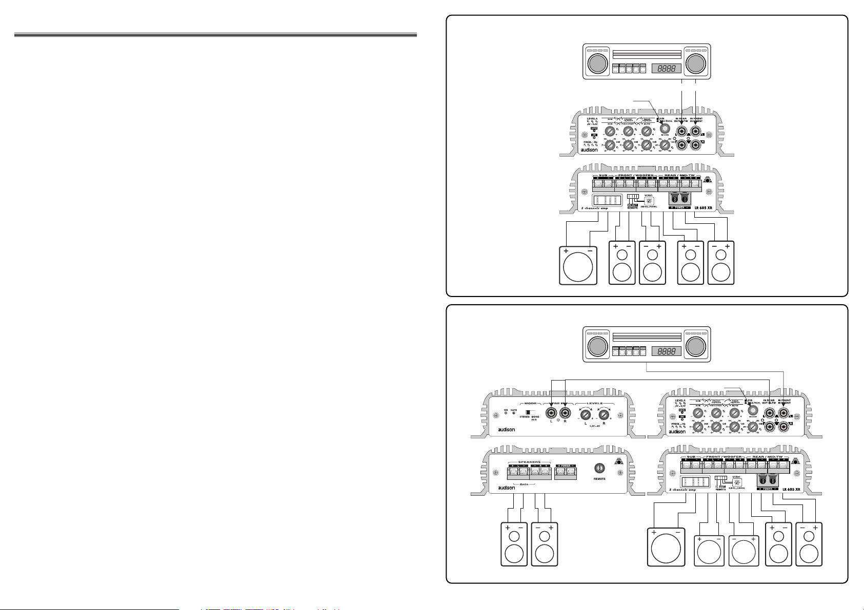
MID-TWEETER REAR
MULTICH.
PRE-OUT
WOOFERSUB MONO MID-TWEETER
LR 52 / LR 72 LR 605 XR
F/R
HI PASS FRONTSUB MONO HI PASS REAR
REAR
PRE-OUT
FRONT
TWO WAY FRONT + SUB SYSTEM AND HI-PASS REAR
FRONT / REAR SYSTEM AND SUBWOOFER
Page 3
A
B
3
ITALIANO
CARATTERISTICHE
LR 605 XR. È un amplificatore a cinque canali dalle elevate caratteristiche musicali. I tratti fondamentali
della sofisticata circuitazione sono: stadi “FRONT END” realizzati con due stadi differenziali complementari,
stadi finali costituiti da transistors in connessione Darlington, transistors finali con capacità in corrente pari
a 15 A ed alimentatore PWM a MOSFETS dall’elevata riserva di energia.
L’apparecchio dispone di quattro canali da 50 W RMS su 4 Ohm ed un canale specifico per il SUBWOOFER
da 200 W RMS su 4 Ohm e 290 W RMS su 2 Ohm. I canali sono asserviti da un sofisticato crossover
configurabile a due vie o a tre vie mediante il pulsante Mode; in entrambe le configurazioni una via, con
pendenza di taglio di 24 dB, è dedicata al SUBWOOFER il quale dispone anche della funzione
FADER
CONSTANT BASS
(livello costante del Subwoofer al variare del livello Front/Rear mediante il controllo
Fader). Il crossover dispone di quattro regolazioni indipendenti per le frequenze di taglio, tre regolazioni per
i livelli di uscita, due connettori di ingresso/uscita preamplificata.
Mode: Selettore posizionato su F/R (Front/Rear).
Consente di realizzare un impianto HI-FI di tipo FRONT/REAR. La sezione FRONT è pilotata dall’ingresso
IN FRONT che gestisce un filtro Lo pass (50Hz - 150Hz) per SUBWOOFER e un filtro Hi pass (50Hz 150Hz), ciascuno dei quali dispone di un controllo di frequenza e di livello. La sezione REAR è pilotata
dall’ingresso IN REAR che gestisce un filtro Hi pass (50Hz - 150Hz) identico a quello della sezione FRONT,
con un proprio controllo di frequenza e di livello.
Mode: Selettore posizionato su MULTICH. (Multichannel).
Consente di realizzare un impianto HI-FI di tipo solo FRONT a due vie + SUB. Singolo ingresso utilizzabile
IN FRONT che gestisce un filtro Lo pass (50Hz - 150Hz) per SUBWOOFER, un filtro Band pass per
WOOFERS (50Hz - 150Hz /150Hz - 850Hz) e un filtro Hi pass per MID-TW (150Hz - 850 Hz).
Le frequenze di crossover tra SUBWOOFER e WOOFER sono gestite da due regolatori di frequenza
indipendenti; la frequenza di taglio tra WOOFER e MID-TW è controllata da un singolo regolatore. Ciascuna
delle tre uscite di potenza è regolata da un proprio controllo di livello. La sezione Hi pass del filtro MID-TW
(150Hz - 850Hz) è replicata sull’apposita uscita preamplificata OUT M-TW e non dispone di regolatore di
volume; il livello di uscita è pari a 0 dB.
Sub remote volume control.
LR 605 XR è predisposto per l’applicazione di un kit accessorio per il controllo esterno del volume del SUB.
Questo accessorio si chiama VCR01K ed è fornito separatamente dalla audison. Il VCR01K si compone
di tre parti:
1) Controllore di volume (VCR01);
2) Modulo da inserire all’interno dello LR 605 XR (VCA);
3)
Cavi di collegamento tra il VCR01 e gli appositi pins posti sul pannello uscite di potenza dello LR 605 XR.
PRECAUZIONI
Per un buon funzionamento dell’apparecchio è importante accertarsi che la temperatura nel luogo dove
esso è installato sia compresa tra 0°C e 55°C.
Il luogo prescelto per l’installazione deve essere ben ventilato ed asciutto.
La tensione di alimentazione è di 12 VCC con negativo a massa. Accertarsi che le caratteristiche
dell’impianto elettrico del veicolo siano adatte per questo apparecchio.
Per una maggiore sicurezza di guida si consiglia l’ascolto ad un livello tale da non coprire i suoni provenienti
dall'esterno dell’auto.
INSTALLAZIONE
Il fissaggio si effettua mediante il serraggio nelle apposite sedi delle 4 viti e relativi distanziali in dotazione.
Per un’ottima riuscita dell’impianto si consiglia di usare i prodotti della linea audison cable che
comprendono: cavi di alimentazione, di segnale, per altoparlanti, connettori RCA e tutti gli accessori per il
completamento del cablaggio.
AVVERTENZE
INGRESSI: Nell’eventualità che il radioriproduttore non avesse in comune la massa di uscita con il telaio si
dovrà collegare la calza del cavo schermato con il telaio del radioriproduttore.
USCITE: Non collegare in alcun caso tra loro oppure a massa le uscite -R e -L. Nel caso si utilizzi un filtro
crossover accertarsi che esso non abbia la massa in comune tra i canali.
REGOLAZIONI: Nel caso si udissero fenomeni di saturazione a livelli di volume non elevato, significa che
il segnale esce distorto dal radioriproduttore. Portare il controllo di volume del radioriproduttore verso un
livello più basso fino alla scomparsa della distorsione.
Regolare successivamente i livelli di taratura dell’amplificatore fino ad udire lievi fenomeni di saturazione.
18
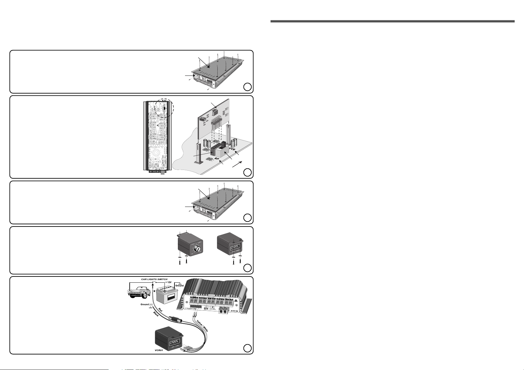
- Connect VCR01 to LR 605 XR amplifier. Polarity
of YELLOW/WHITE cables is not important.
- Collegare il VCR01 all’amplificatore LR 605 XR.
La polarità dei cavi GIALLO/BIANCO non è
importante.
- Connecter le VCR01 à l’amplificateur LR 605 XR.
La polarité des câbles JAUNE/BLANC n’est pas
importante.
- Verbinden Sie den VCR01 mit dem Verstärker
LR 605 XR. Die Polarität des GELB/WEIßEN
Kabels ist nicht wichtig.
FRONT REAR
1- Take off the power outputs panel A (2 screws).
- Smontare il pannello uscite di potenza A (2 viti).
- Démonter le panneau des sorties de puissance A (2 vis).
- Entfernen Sie das Panel bei den Lautsprecherausgängen (2 Schrauben).
2- Take off the bottom B (8 screws).
- Smontare il fondo B (8 viti).
- Démonter le fond B (8 vis).
- Entfernen Sie den Boden B (8 Schrauben).
1-Put VCA module into connector C.
- Inserire il modulo VCA nel connettore C.
- Insérer le module VCA dans le connecteur C.
- Stecken Sie das VCA-Modul in Steckverbindung C.
2-Put the switch S on VCR.
- Posizionare il deviatore S su VCR.
- Placer le déviateur S sur VCR.
- Stellen Sie den Schalter S auf VCR.
Important: In case you take VCA module off, put S on BP.
Importante: In caso di rimozione del modulo VCA
riposizionare S su BP.
Important: En cas de retrait du module VCA, replacer S
sur BP
.
Wichtig: Sollten Sie das VCA-Modul einmal entfernen,
stellen Sie S auf BP.
- Fix VCR01 volume control in a suitable position for its use by the car
driver (2 screws).
- Fissare il controllore di volume VCR01 nella posizione idonea per la
monopolazione da parte del conducente (2 viti).
- Fixer le bouton de réglage du volume VCR01 dans une position adaptée
à sa manipulation de la part du conducteur (2 vis).
- Montieren Sie den Lautstärkeregler VCR01 an einem für den Fahrer
problemlos zugänglichen Ort. (2 Schrauben).
VCA
C
S
BP
VCR
A
B
Sub remote volume control kit (Optional)
VCR01K: VCR01 + VCA Module
Connection according to instructions from 1 to 5.
Procedere al collegamento seguendo i passi da 1 a 5.
Procéder au montage en suivant les phases de 1 à 5.
Anschluß gemäß der Anleitung von Bild 1 bis 5.
1
2
3
4
5
1- Mount the bottom B again (8 screws).
- Rimontare il fondo B (8 viti).
- Remonter le fond B (8 vis).
- Schrauben Sie den Boden B wieder fest. (8 Schrauben).
2- Mount the power outputs panel A again (2 screws).
- Rimontare il pannello uscite di potenza A (2 viti).
- Remonter le panneau des sorties de puissance A (2 vis).
- Schrauben Sie das Panel bei den Lautsprecherausgängen wieder fest. (2 Schrauben).
Page 4

4
FRANÇAIS
CARACTÉRISTIQUES
LR 605 XR. C’est un amplificateur à cinq voies aux performances musicales élevées. Les éléments
fondamentaux de ce circuit d’exception sont: stades “FRONT END” réalisés avec deux stades différentiels
complémentaires, stades finals constitués de transistors en connexion Darlington, transistors finals avec une
capacité en courant équivalente à 15 A et une alimentation PWM à MOSFETS à grande réserve d’énergie.
L’appareil dispose de quatre voies de 50 W RMS sur 4 Ohm et d’une voie spéciale pour le SUBWOOFER
de 200 W RMS sur 4 Ohm et 290 W RMS sur 2 Ohm. Les voies sont soumises à un filtre actif exceptionnel
réglabe sur deux ou trois voies par le bouton Mode; dans l’une ou l’autre disposition, une voie, qui a une
pente de coupe de 24 dB, est consacrée au SUBWOOFER, qui dispose même de la fonction FADER
CONSTANT BASS (niveau constant du Subwoofer lorsque le niveau Front/Rear est varié par le réglage
Fader). Le filtre actif dispose de quatre réglages indépendants pour les fréquences de coupe, trois réglages
pour les niveaux de sortie, deux connecteurs d’entrée/sortie préamplifiée.
Mode: Bouton de commande positionné sur F/R (Front/Rear) (Avant/Arrière).
Il permet de réaliser une installation HI-FI du type FRONT-REAR. La section FRONT est commandée par
l’entrée IN FRONT qui gère un filtre Lo pass (50Hz - 150Hz) pour SUBWOOFER et un filtre Hi pass (50Hz
- 150Hz), disposant chacun d’un contrôle de fréquence et de niveau. La section REAR est commandée par
l’entrée IN REAR qui gère un filtre Hi pass (50Hz - 150Hz) identique à celui de la section FRONT, avec son
propre contrôle de fréquence et de niveau.
Mode: bouton de commande positionné sur MULTICH. (Multichannel).
Il permet de réaliser une installation HI-FI de type uniquement FRONT à deux voies + SUB. Entrée simple
utilisable IN FRONT qui gére un filtre Lo pass (50Hz - 150Hz) pour SUBWOOFER, un filtre Band pass pour
WOOFERS (50Hz - 150Hz /150Hz - 850Hz) et un filtre Hi pass pour MID-TW (150Hz - 850 Hz).
Les fréquences de coupe entre SUBWOOFER et WOOFER sont gérées par boutons de réglage de
fréquence indépendants; la fréquence de coupe entre WOOFER et MID-TW est controllée par un simple
bouton de réglage. Chacune des trois sorties de puissance est réglée par un propre contrôle de niveau. La
section Hi-pass du filtre MID-TW (150Hz - 850Hz) est reproduite sur la sortie adéquate préamplifiée OUT
M-TW et ne dispose pas de bouton de réglage du volume; le niveau de sortie est équivalent à 0 dB.
Sub remote volume control.
LR 605 XR est conçu pour l’éventuel ajout d’un kit accessoire pour le contrôle externe du volume du SUB.
Cet accessoire, appelé VCR 01 K, est fourni séparément par audison. Le VCR01K se compose de trois
parties:
1) Contrôleur de volume (VCR01);
2) Module à insérer à l’intérieur du LR 605 XR (VCA);
3) Câbles de liaison entre le VCR01 et les agrafes prévues à cet effet sur le panneau des sorties de
puissance du LR 605 XR.
PRÉCAUTIONS
Pour un bon fonctionnement de l’appareil, s’assurer que la température de l’endroit où il est installé soit
comprise entre 0°C et 55°C.
L’endroit choisi pour l’installation doit être bien aéré et sec.
La tension d’alimentation est de 12 VCC avec négatif à la masse. S’assurer que les caractéristiques de
l’installation électrique du véhicule soient adaptées à cet appareil.
Pour une conduite sans risque, choisir un niveau d’écoute ne couvrant pas le bruit du trafic environnant.
INSTALLATION
Pour le montage, utiliser les vis et rondelles fournies à cet effet. Pour un résultat optimum de l’installation, il
est recommandé d’utiliser les produits de la ligne audison cable qui comprend: câbles d’alimentation,
câbles signal, câbles pour haut-parleurs, connecteurs RCA et tous les accessoires complétant le
branchement.
ATTENTION
ENTRÉES: Si la masse de sortie de l’autoradio n’est pas la même que celle du châssis, relier la gaine du
câble isolant au châssis de l’autoradio.
SORTIES: Ne jamais connecter entre elles ou sur la masse les sorties -R et -L. Avant d’utiliser un filtre actif,
s’assurer qu’il n’ait pas de masse commune aux voies.
RÉGLAGES: Si des phénomènes de saturation apparaissent à un niveau de volume modéré, cela signifie
que le signal sort distordu de l’autoradio. En ce cas, abaisser le volume de l’autoradio jusqu’à ce que le
phénomène disparaisse. Ensuite, régler les niveaux de l’amplificateur jusqu’à n’entendre que de légers
phénoménes de saturation.
17
FRONT
Linke und rechte Lautsprecherklemmen für vordere Kanäle. Sie
werden von einem Hochpaß, der
durch F2im Bereich zwischen 50
Hz und 150 Hz (12 dB/Okt)
einstellbar ist, gefiltert.
Das gelieferte Signal ist
stereophon (Brückenbetrieb nicht
möglich).
REAR
Linke und rechte
Lautsprecherklemmen für
hintere Kanäle. Sie werden von einem Hochpaß,
der durch F3im Bereich
zwischen 50 Hz und 150
Hz (12 dB/Okt) einstellbar ist, gefiltert. Das
gelieferte Signal ist stereophon (Brückenbetrieb
nicht möglich).
F/R
Front/Rear
In dieser Konfiguration erlaubt
der Verstärker
die Realisierung
einer HochpaßFRONT +
Hochpaß-REAR
+ SUB-Anlage.
SUB
Lautsprecherklemmen
für SUB-Kanäle. Sie
werden von einem
Tiefpaß, der durch
F1im Bereich zwischen 50 Hz und
150 Hz (24 dB/Okt)
einstellbar ist, gefiltert. Das gelieferte
Signal ist monaural
(Mix L + R).
MULTICH.
Multichannel
In dieser
Konfi-
guration
erlaubt
der Verstärker
die Realisierung
einer ZweiwegFRONT + SUBAnlage
.
SUB
Lautsprecherklemmen
für SUB-Kanäle. Sie
werden von einem
Hochpaß, der durch
F1im Bereich zwischen 50 Hz und
150 Hz (24 dB/Okt)
einstellbar ist, gefiltert. Das gelieferte
Signal ist monaural
(Mix L + R).
WOOFER
Linke und rechte Lautsprecherklemmen für Wooferkanäle. Sie
werden von einem Hochpaß, der
durch F2im Bereich zwischen 50
Hz und 150 Hz (12 dB/Okt)
einstellbar ist, sowie einem
Tiefpaß, der durch F4von 150 Hz
bis 850 Hz (12 dB/Okt) einstellbar
ist, gefiltert. Das gelieferte Signal
ist stereophon (Brückenbetrieb
nicht möglich).
MID-TW
Linke und rechte
Lautsprecherklemmen für
MID-TW-Kanäle. Sie werden von einem Hochpaß,
der durch F4im Bereich
zwischen 150 Hz und
850 Hz (12 dB/Okt) einstellbar ist, gefiltert. Das
gelieferte Signal ist stereophon (Brückenbetrieb
nicht möglich).
POWER
Eingangsklemmen für die
Stromversorgung des
Verstärkers. Verbinden
Sie positive und negative
Kabel entsprechend der
Kennzeichnungen. Die
angelegte Spannung
muß zwischen 11 und 15
VDC betragen.
ANSCHLUßKONFIGURATION
LAUTSPRECHERKLEMMEN
IN
Ferneinschaltleitung, die vom
Autoradio (oder einer anderen
Quelle, die mit einem
Fernschalteingang für
Verstärker ausgerüstet ist)
kommt. Angelegte Spannung
muß zwischen 7 und 15 VDC
betragen.
FERNEINSCHALT-ANSCHLUSS
STROMVERSORGUNG
VCR01
Anschlußklemmen für
die Subwoofer
pegel-Fernbedienung
VCR01
(optional).
SUB VOL.
CONTROL
OUT
Ausgang für den Anschluß
weiterer Verstärker der
Anlage. Er muß zum simultanan Einschalten der kompletten Anlage mit dem
Ferneinschalt-Anschluß der
jeweiligen Verstärker verbunden werden. Die Spannung
entspricht der am Eingang.
MODUS
(Konfiguration
des Verstärkers)
1
Page 5

DEUTSCH
EIGENSCHAFTEN
Der LR 605 XR ist ein Fünfkanal-Endverstärker mit hohen musikalischen Qualitäten. Die hervorragenden
Eigenschaften seiner fortschrittlichen Schaltkreise sind: „FRONT END“-Stufen, die mittels zweier
komplementärer Differenzstufen aufgebaut sind; Endstufen, die aus Transistoren in Darlington-Schaltung
bestehen; Endtransistoren mit einer Stromfähigkeit von 15 A; ein MOSFET-Schaltnetzteil mit hoher
Energiereserve.
Dieses Gerät hat vier Kanäle mit je 50 W RMS an 4 Ohm und einen Kanal mit 200 W RMS an 4 Ohm sowie
290 W RMS an 2 Ohm, der für SUBWOOFER bestimmt ist. Die Kanäle werden von einer hochwertigen
Frequenzweiche mit Signalen versorgt. Sie kann durch den MODE-Schalter entweder als Zweiweg-Weiche
plus SUB oder als Dreiweg-Weiche konfiguriert werden. In beiden Konfigurationen ist einer der Wege, der
eine Flankensteilheit von 24 dB aufweist, für den SUBWOOFER reserviert und mit einer “FADER CONSTANT
BASS”-Funktion ausgerüstet. (Subwoofer behält konstanten Pegel, wenn das Front/Rear-Verhältnis den
Fader variiert wird.) Die Frequenzweiche hat vier unabhängige Einstellregler für die Trennfrequenzen, drei
Regler für den Ausgangspegel und zwei vorverstärkte EAusgangs/Eingangs-Buchsen.
Modus: Schalter auf F/R (Front(Vorn)/Rear(Hinten))
Dieser Modus erlaubt, eine HiFi-FRONT/REAR-Anlage aufzubauen. Die FRONT-Sektion wird von den IN
FRONT-Eingängen versorgt, die ein Tiefpaßfilter (50Hz-150Hz) für den SUBWOOFER und ein Hochpaßfilter
(50Hz-150Hz) beinhalten; jedes Filter hat einen Pegel- und Frequenzregler. Die REAR-Sektion wird von den
IN REAR-Eingängen versorgt und beinhaltet ein Hochpaßfilter (50Hz-150Hz) gleich dem der FRONT-Sektion
mit seinen eigenen Frequenz- und Pegel-Reglern.
Modus: Schalter auf MULTICH. (Multichannel)
Dieser Modus erlaubt, eine HiFi-Zweiwege-Anlage mit FRONT + SUB aufzubauen. Dazu kann ausschließlich
der IN FRONT-Eingang benutzt werden. Er beinhaltet ein Tiefpaßfilter (50Hz-150Hz/150Hz-850Hz) für
SUBWOOFER, ein Bandpaßfilter (150Hz-850Hz) für WOOFER und ein Hochpaßfilter (150Hz-850Hz) für
MID-TW. Die Übergangsfrequenzen zwischen SUBWOOFER und WOOFER können durch zwei getrennte
Frequenzregler eingestellt werden. Die Übergangsfrequenz zwischen WOOFER und MID-TW wird mit einem
einzigen Regler eingestellt. Die Hochpaßsektion des MID-TW -Filters (150Hz-850Hz) wird ebenfalls auf den
richtigen vorverstärkten Ausgang des M-TW -Zweiges geleitet; dieser hat keinen eigenen Pegelregler. Der
Ausgangspegel entspricht 0 dB.
Fernbedienung für Subwoofer-Pegel.
Der LR 605 XR ist für die Nachrüstung mit einer Fernbedienung für den SUBWOOFER-Pegel vorbereitet.
Dieses Zubehör mit der Bezeichnung VCR01K kann von audison separat bezogen werden. Das VCR01K
besteht aus drei Teilen:
1) Lautstärkeregler (VCR01);
2) Einsteckmodul für LR 605 XR (VCA);
3) Verbindungskabel zwischen VCR01 und den richtigen Anschlüssen auf dem LautstpercheranschlußPanel des LR 605 XR.
VORSICHTSMASSNAHMEN
Damit dieses Gerät ordnungsgemäß funktionieren kann, ist es wichtig, es an einem Platz zu installieren, an
dem die Temperaturen nicht unter 0° C fallen oder über 55° C steigen.
Das Gerät muß an einem trockenen und gut belüfteten Platz installiert werden.
Die Versorgungsspannung beträgt 12 V Gelichspannung mit Minus an Masse. Stellen Sie sicher, daß die
Charakteristika des elektrischen Systems Ihres Fahrzeuges mit dem Gerät kompatibel sind.
Aus Gründen der Fahrsicherheit empfehlen wir, daß Sie mit einer Lautstärke Musik hören, die externen
Verkehrsgeräusche nicht übertönt.
INSTALLATION
Benutzen Sie für die Befestigung die vier beigelegten selbstschneidenden Schrauben und PlastikSchutzringe. Für beste Klangergebnisse empfehlen wir die Verwendung der Produkte von audison cable, um
die Installation abzuschließen. Diese umfassen: Stromkabel, Signalkabel, Lautsprecherkabel Cinchsteckerund Buchsen und alles Zubehör, das Sie benötigen, um eine Verkabelung durchzuführen.
WARNUNGEN
EINGÄNGE: Wenn bei dem verwendeten Autoradio die Signalmasse nicht auf das Chassis gelegt ist, muß
die Abschirmungen der Cinchkabel mit dem Chassis des Radios verbunden werden.
AUSGÄNGE: Verbinden Sie niemals die Minuspole der Lautsprecherausgänge mit der Karosserie oder der
Masse. Wenn eine passive Frequenzweiche benutzt wird, stellen Sie sicher, daß die beiden Kanäle der
Weiche keine gemeinsame Masse aufweisen.
EINSTELLUNGEN: Wenn Sie Übersteuerungsanzeichen auch bei kleinen Lautstärken hören, heißt das, daß
schon vom Autoradio ein verzerrtes Signal kommt.Regeln Sie die Lautstärke am Autoradio herunter, bis keine
Verzerrungen mehr zu hören sind. Dann stellen Sie die Pegelregler des Verstärkers so ein, daß Sie gerade
eben Übersteuerungsanzeichen hören können.
5
16
MULTICH.
Multichannel
In dieser
Stellung
erlaubt der
Verstärker die
Realisierung
einer
ZweiwegFRONT +
SUB-Anlage
.
F
4
TiefpaßÜbergangsfre
quenz des
WOOFERKanals und
Hochpaß für
die MID-TWKanäle.
(
150Hz-850Hz
12dB/Okt.)
F
1
TiefpaßÜbergangsfrequenz
des SUBKanals
.
(
50Hz-150Hz
24dB/Okt.
)
F
2
HochpaßÜbergangsfrequenz des
WOOFERKanals.
(
50Hz-150Hz
12dB/Okt.)
F
3
Nicht
aktiv.
OUT MID-TW
Vorverstärkter
HochpaßAusgang des
MID-TW-Filters
für einen
weiteren
Verstärker.
Signalpegel:
0 dB.
F/R
Front/Rear
In dieser
Stellung
erlaubt der
Verstärker die
Realisierung
einer HochpaßFRONT +
HochpaßREAR + SUBAnlage.
F
4
Nicht
aktiv.
F
1
TiefpaßÜbergangsfrequenz
des SUBKanals.
(
50Hz-150Hz
24dB/Okt.
)
IN REAR
Eingang zur
Ansteuerung
der REARKanäle.
F
2
HochpaßÜbergangsfrequenz
des FRONTKanals.
(
50Hz-150Hz
12 dB/Okt.)
F
3
HochpaßÜbergangsfrequenze
der REARKanäle.
(
50Hz-150Hz
12dB/Okt.)
IN FRONT
Gemeinsamer
Eingang zur
Ansteuerung
der SUB- und
FRONTHochpaßKanäle.
IN FRONT
Gemeinsamer
Eingang zur
Ansteuerung
der SUB-,
WOOFER- und
MID-TWKanäle.
REGLER UND FUNKTIONEN
ON
Leuchtet, wenn der Verstärker eingeschaltet ist.
SAFE
Wenn diese LED leuchtet, hat eine der Schutzschaltungen angesprochen:
nämlich im Fall von Überhitzung (Temperatur höher als 80°C) oder Anomalien
am Ausgang (Vorhandensein von Gleichspannung, Kurzschluß oder
gefährlich niedriger Impedanz). Wenn die Schutzschaltungen eingreifen,
schaltet der Verstärker stumm. Schalten Sie das Gerät dann ab.Nachdem der
Fehler behoben wurde, schalten Sie den Verstärker wieder ein.
ANZEIGE - LEDS
V1- V2- V
3
Pegelregler für SUB,
FRONT/WOOFER und
REAR/MID-TW-Kanäle.
(Kanäle variieren je nach
Stellung des MODESchalters).
PEGELREGLER
FREQUENZREGLER
MODUS
AUXILIARY-
AUSGANG/EINGANG
GEMEINSAME
R EINGANG
1
1
Page 6

UNIT FIXING
6
15
FRONT
Sorties de puissance Left et Right
pour les voies FRONT. Elles sont
filtrées Hi pass, en une gamme de
fréquences comprises entre 50Hz
et 150Hz (12dB/Ott.), réglable par
F2. Le signal disponible est de type
STÉRÉO. (Disposition en pont non
prévue).
REAR
Sorties de puissance Left
et Right pour les voies
REAR. Elles sont filtrées
Hi pass, en une gamme
de fréquences comprises
entre 50Hz et 150Hz
(12dB/Ott.), réglable par
F3. Le signal disponible
est de type STÉRÉO.
(Disposition en pont non
prévue).
INPUT REAR
Dans cette position, l’amplificateur permet de
réaliser un
système Hi Pass
FRONT + Hi
Pass REAR +
SUB.
SUB
Sortie de puissance
des voies SUB. Elle
est filtrée Lo pass, en
une gamme de fré-
quences comprises
entre 50Hz et 150Hz
(24dB/Ott.), réglable
par F1. Le signal
disponible est de type
MONO, (Mix L + R).
OUTPUT
MID-TW
Dans cette
position,
l’ amplificateur
permet de
réaliser un
systè me
FRONT à deux
voies + SUB.
SUB
Sortie de puissance
des voies SUB. Elle
est filtrée Lo pass, en
une gamme de
fréquences comprises
entre 50Hz et 150Hz
(24dB/Ott.), réglable
par F1. Le signal
disponible est de type
MONO, (Mix L + R).
WOOFER
Sorties de puissance Left et Right
pour les voies WOOFER. Elles
sont filtrées Hi pass, en une
gamme de fréquences comprises
entre 50Hz et 150Hz (12dB/Ott.),
réglable par F2et Lo pass, en une
gamme de fréquences comprises
entre 150Hz et 850Hz (12dB/Ott.),
réglable par F4. Le signal
disponible est de type STÉRÉO.
(Disposition en pont non prévue).
MID-TW
Sorties de puissance Left et
Right pour les voies MIDTW. Elles sont filtrées Hi
pass, en une gamme de
fréquences comprises entre
150Hz et 850Hz (12dB/Ott.)
,
réglable par F4. Le signal
disponible est de type
STÉRÉO. (Disposition en
pont non prévue).
POWER
Borne d’entrée pour l’alimentation de l’amplificateur. Relier le positif et le
négatif de la batterie
selon les polarités indiquées. Le voltage appliqué doit être compris
entre 11 et 15 VDC.
DISPOSITION DES BORNES DE CONNECTION
BORNES DE SORTIE
IN
Bouton de commande de mise
en action pour l’amplificateur,
provenant de l’autoradio (ou de
toute autre source dotée de
sortie pour la commande remoe pour les amplificateurs).
Le voltage appliqué doit être
compris entre 7 et 15 VDC.
REMOTE
BORNES
D’ALIMENTATION
VCR01
Terminaux de
connection
pour le dispositif de contrôle du volume à distance
VCR01
(en option).
SUB VOL.
CONTROL
OUT
Sortie pour les amplificaeurs du système de reproduction. A relier au REMOTE IN de l’amplificateur successif pour permettre l’allu-
mage simultané de toute l’installation. Voltage disponible
semblable au REMOTE IN.
MODE
(Disposition de
l’amplificateur)
1
SERVICE CONNECTIONS
0
VCR 01
min max
Level
40
A
Page 7

7
BLOCK DIAGRAM
14
MULTICH.
Multichannel
Dans cette
position,
l’amplificateu
r permet de
réaliser un
systè me
FRONT à
deux voies +
SUB.
F
4
Fréquence de
coupe Lo pass
des voies
WOOFER, et
Hi-pass des
voies MID-TW.
(
150Hz-850Hz
12dB/Ott.)
F
1
Fréquence
de coupe
Lo
pass de la
voie SUB.
(
50Hz-150Hz
24dB/Ott.)
F
2
Fré quence
de coupe Hi
pass des
voies
WOOFER.
(
50Hz-150Hz
12dB/Ott.)
F
3
Bouton
de
comm
ande
non
activé.
OUT MID-TW
Sortie
préamplifiée Hi-
pass du filtre
MID-TW
destinée à un
amplificateur
supplémentaire
. Niveau de
signal 0 dB.
F/R
Front/Rear
Dans cette
position,
l’amplificateur
permet de
réaliser un
système Hi
Pass FRONT
+ Hi Pass
REAR + SUB.
F
4
Bouton
de
comma
nde non
activé.
F
1
Fréquence
de coupe Lo
pass de la
voie SUB.
(
50Hz-150Hz
24dB/Ott.
)
IN REAR
Entrée utilisée
pour
commander les
voies REAR.
F
2
Fré quence
de coupe Hi
pass des
voies
FRONT.
(
50Hz-150Hz
12 dB/Ott.)
F
3
Fré quence
de coupe Hi
pass des
voies REAR.
(
50Hz-150Hz
12dB/Ott.)
IN FRONT
Entrée générale
pour
commander les
voies SUB et
FRONT Hi
Pass.
IN FRONT
Entré e
générale pour
commander
les voies SUB,
WOOFER et
MID-TW.
BOUTONS DE COMMANDE ET FONCTIONS
ON
Il indique la mise en fonction de l’amplificateur.
SAFE
Il indique l’intervention des protections: température excessive (max 80°C
)
ou anomalies de sortie (présence de courant continu, court-circuit ou
impédance de charge trop basse). L’intervention des protections stoppe le
fonctionnement de l’appareil. Éteindre l’amplificateur, éliminer la cause de
la panne puis rallumer l’appareil.
SIGNAUX LUMINEUX
V1- V2- V
3
Réglages de niveau pour
les voies SUB, FRONT /
WOOFER et REAR/MIDTW (les voies varient
selon la position du
bouton de commande
MODE).
CONTRÔLES
DE NIVEAU
CONTROLES DE FRÉQUENCE
MODE
ENTRÉE/SORTIE
AUXILIAIRE
ENTRÉE
GÉNÉRALE
1
1
VCR
With VCA
BP
Without VCA
RL RR FRFL
MIX
MONO
24 dB/Oct.
LO
50Hz - 150Hz
SUB
VCR BP
IN
OUT
SUB
LEVELS
0.3 - 4 V
FADER
CONSTANT
BASS
VCA
MODULE
EXTERNAL
SUB REMOTE
VOLUME
CONTROL
SUB AMPLIFIER
MULTICH. F/R
1/3 SW
MODE
12 dB/Oct.
LO
150Hz - 850Hz
WOOFER/MID-TW
12 dB/Oct.
50Hz - 150Hz
FRONT/WOOFER
FRONT/WOOFER
LEVELS
0.3 - 4 V
HI
FRONT/WOOFER
AMPLIFIERS
MULTICH. F/R
1/3 SW
12 dB/Oct.
50Hz - 150Hz
MULTICH. F/R
1/3 SW
MODE
MODE
REAR
HIHI
REAR/MID-TW
LEVELS
0.3 - 4 V
REAR/MID-TW
AMPLIFIERS
Page 8

8
ITALIANO
DATI TECNICI
ALIMENTAZIONE 11 ÷ 15 VDC
ASSORBIMENTO A VUOTO 1,8 A
ASSORBIMENTO MAX (Pot. Nominale) 60 A
MAX DYNAMIC POWER (5 ch x 4 Ohm) 60 W x 4 + 250 W
POTENZA NOMINALE CONT. (Toll. +10%; -5 %)
5 ch x 4 Ohm; 0,3 % THD; 12 VDC
40 W x 4 (RMS) + 150 W (RMS)
POTENZA OUT CONTINUA (5 ch x 4 Ohm; 13,8 VDC)
50 W x 4 (RMS) + 200 W (RMS)
POTENZA OUT CONTINUA (4 ch x 4 Ohm; 1 ch x 2 Ohm; 13,8 VDC)
50 W x 4 (RMS) + 290 W (RMS)
DISTORSIONE THD (1 KHz; 90 % Pot. Nominale) 0,05 %
BANDA PASSANTE (-3 dB; Pot. Nominale) 4 Hz ÷ 70 KHz
FREQUENZA DI CROSSOVER
LO-PASS SUBWOOFER 50 Hz ÷ 150 Hz
HI-PASS FRONT 50 Hz ÷ 150 Hz
LO/HI-PASS FRONT 150 Hz ÷ 850 Hz
HI-PASS REAR 50 Hz ÷ 150 Hz
PENDENZA FILTRI
12 dB/Ott. (24 dB/Ott. Subwoofer)
FATTORE DI SMORZAMENTO (4 Ohm) 100
TEMPO DI SALITA 2,5 µS
RAPPORTO SEGNALE RUMORE (1 VRMS Input) 103 dBA
SENSIBILITÀ D’INGRESSO 0,3 V ÷ 4 VRMS
IMPEDENZA D’INGRESSO 15 KOhm
IMPEDENZA DI CARICO 8 - 4 - 2 Ohm
REMOTE IN - OUT 7 ÷ 15 VDC
DIMENSIONI (BxAxL) 175 x 50 x 475 mm
ENGLISH
TECHNICAL DATA
POWER SUPPLY 11 ÷ 15 VDC
IDLING CURRENT 1.8 A
MAX COMSUMPTION (Nominal Pwr) 60 A
MAX DYNAMIC POWER (5 ch x 4 Ohms) 60 W x 4 + 250 W
CONT. NOMINAL POWER (Tol. +10%; -5 %) VDC
5 ch x 4 Ohms; 0.3 % THD; 12 VDC
40 W x 4 (RMS) + 150 W (RMS)
CONT. OUT POWER (5 ch x 4 Ohms; 13.8 VDC)
50 W x 4 (RMS) + 200 W (RMS)
CONT. OUT POWER
(4 ch x 4 Ohms; 1 ch x 2 Ohms; 13.8 VDC) 50 W x 4 (RMS) + 290 W (RMS)
DISTORTION THD (1 KHz; 90 % Nominal Pwr) 0.05 %
BANDWIDTH (-3 dB; Nominal Pwr) 4 Hz ÷ 70 KHz
CROSSOVER FREQUENCY
LO-PASS SUBWOOFER 50 Hz ÷ 150 Hz
HI-PASS FRONT 50 Hz ÷ 150 Hz
LO/HI-PASS FRONT 150 Hz ÷ 850 Hz
HI-PASS REAR 50 Hz ÷ 150 Hz
FILTERS SLOPE
12 dB/Oct. (24 dB/Oct. Subwoofer)
DAMPING FACTOR (4 Ohms) 100
RISE TIME 2.5 µS
SIGNAL / NOISE RATIO (1 VRMS input) 103 dBA
INPUT SENSITIVITY 0.3 V ÷ 4 VRMS
INPUT IMPEDANCE 15 KOhms
LOAD IMPEDANCE 8 - 4 - 2 Ohms
REMOTE IN - OUT 7 ÷ 15 VDC
DIMENSIONS (BxHxL) 175 x 50 x 475 mm (6.88 x 1.96 x 18.70 inch)
13
FRONT
Uscite di potenza Left e Right per i
canali FRONT. Sono filtrate passa
alto, in una gamma di frequenze
comprese tra 50Hz e 150Hz
(12dB/Ott.), regolabile tramite F2.
Il segnale disponibile è di tipo
STEREO.(Configurazione a ponte
non prevista).
REAR
Uscite di potenza Left e
Right per i canali REAR.
Sono filtrate passa alto, in
una gamma di frequenze
comprese tra 50Hz e
150Hz (12 dB/Ott.), regolabile tramite F3. Il segnale disponibile è di tipo
STEREO. (Configurazione
a ponte non prevista).
F/R
Front/Rear
In questa
configurazione
l’amplificatore
consente di
realizzare un
sistema
Hi Pass
FRONT +Hi
Pass REAR +
SUB.
SUB
Uscita di potenza dei
canali SUB. É filtrata
passa basso, in una
gamma di frequenze
comprese tra 50Hz e
150Hz (24dB/Ott.),
regolabile tramite F1.
Il segnale disponibile
è di tipo MONO.
(Mix L + R)
MULTICH.
Multichannel
In questa
configurazione
l’ amplificatore
consente di
realizzare un
sistema FRONT
a due vie +
SUB.
SUB
Uscita di potenza dei
canali SUB. É filtrata
passa basso, in una
gamma di frequenze
comprese tra 50Hz e
150Hz (24dB/Ott.),
regolabile tramite F1.
Il segnale disponibile
è di tipo MONO. (Mix
L + R)
WOOFER
Uscite di potenza Left e Right per i
canali WOOFER. Sono filtrate passa
alto, in una gamma di frequenze
compresa tra 50Hz e 150Hz
(12dB/Ott.), regolabile tramite F2e
passa basso, in una gamma di
frequenze compresa tra 150Hz e
850Hz (12dB/Ott.), regolabile
tramite F4. Il segnale disponibile è di
tipo STEREO. (Configurazione a
ponte non prevista).
MID-TW
Uscite di potenza Left e
Right per i canali MID-TW.
Sono filtrate passa alto, in
una gamma di frequenze
compresa tra 150Hz e
850Hz (12 dB/Ott.), regolabile tramite F4. Il segnale disponibile è di tipo
STEREO. (Configurazione
a ponte non prevista).
POWER
Morsetti di ingresso per
l’alimentazione dell’amplificatore. Collegare il positivo
ed il negativo di batteria
secondo le polarità
indicate. La tensione
applicata deve essere
compresa tra 11 e 15 VDC.
CONFIGURAZIONE DEI MORSETTI DI COLLEGAMENTO
MORSETTI DI USCITA
IN
Comando di accensione per
l’amplificatore proveniente
dall’autoradio (
o qualsiasi tipo
di sorgente provvista di apposita uscita per il comando di
remote per gli amplificatori
).La
tensione applicata deve essere compresa tra 7 e 15 VDC.
REMOTE
MORSETTI DI
ALIMENTAZIONE
VCR01
Terminali di
collegamento
per il dispositivo di controllo di volume a distanza VCR01
(opzionale).
SUB VOL.
CONTROL
OUT
Uscita per gli altri amplificatori dell’impianto di riproduzione. Va collegata al REMOTE IN dell’amplificatore successivo per consentire l’accensione simultanea di tutto
l’impianto. Tensione disponibile pari al REMOTE IN.
MODE
1
Page 9

DEUTSCH
TECHNISCHE DATEN
SPANNUNGSVERSORGUNG 11 ÷ 15 VDC
RUHESTROM 1,8 A
MAXIMALSTROM (Nennleistung) 60 A
MAX. DYNAMISCHE LEISTUNG (5 Kanäle, je 4 Ohm) 4 x 60 W + 250 W
DAUER-NENNLEISTUNG (Toleranz +10%, -5%)
5 Kanäle, je 4 Ohm, 0,3% Klirrfaktor, 12 VDC 4 x 40 WRMS + 150 WRMS
DAUER-NENNLEISTUNG (5 Kanäle, je 4 Ohm, 13,8 VDC) 4 x 50 WRMS + 200 WRMS
DAUER-NENNLEISTUNG
(4 Kanäle, je4Ohm, 1Kanal 2Ohm, 13,8 VDC)
4 x 50 WRMS + 290 WRMS
VERZERRUNGEN THD (1 kHz, 90% Nennleistung) 0,05
BANDBREITE (-3 dB, Nennleistung) 4 Hz ÷ 70 kHz
ÜBERNAHMEFREQUENZEN
TIEFPASS SUBWOOFER 50 Hz ÷ 150 Hz
HOCHPASS FRONT 50 Hz ÷ 150 Hz
TIEF/HOCHPASS FRONT 150 Hz ÷ 850 Hz
HOCHPASS REAR 50 Hz ÷ 150 Hz
FLANKENSTEILHEIT FILTER
12 dB/Okt (24 dB/Okt. Subwoofer)
DÄMPFUNGSFAKTOR 100
ANSTIEGSZEIT 2,5 µS
SIGNAL/RAUSCHABSTAND (Eingangsspannung 1VRMS) 103 dBA
EINGANGSEMPFINDLICHKEIT 0,3 V ÷ 4 VRMS
EINGANGSIMPEDANZ 15 kOhm
LASTIMPEDANZ 8 - 4 - 2 Ohm
FERNBEDIENUNGS-EIN/AUSGANG 7 ÷ 15 VDC
ABMESSUNGEN (BxHxT) 175 x 50 x 475 mm
9
FRANÇAIS
DONNÉES TECHNIQUES
ALIMENTATION 11 ÷ 15 VDC
CONSOMMATION MIN. 1,8 A
CONSOMMATION MAX. (Puissance Nominale) 60 A
MAX DYNAMIC POWER (5 ch x 4 Ohm) 60 W x 4 + 250 W
PUISSANCE NOMINALE CONTINUE (Toll. +10%; -5 %)
5 ch x 4 Ohm; 0,3 % DHT; 12 VDC
40 W x 4 (RMS) + 150 W (RMS)
PUISSANCE SORTIE CONT. (5 ch x 4 Ohm; 13,8 VDC)
50 W x 4 (RMS) + 200 W (RMS)
PUISSANCE SORTIE CONT.
(4 ch x 4 Ohm; 1 ch x 2 Ohm; 13,8 VDC)
50 W x 4 (RMS) + 290 W (RMS)
DISTORSION HARM. TOTALE (1 KHz; 90 % Puiss. Nom.) 0,05 %
BANDE PASSANTE (-3 dB; Puiss. Nom.) 4 Hz ÷ 70 KHz
FREQUENCE DE COUPURE
LO-PASS SUBWOOFER 50 Hz ÷ 150 Hz
HI-PASS FRONT 50 Hz ÷ 150 Hz
LO/HI-PASS FRONT 150 Hz ÷ 850 Hz
HI-PASS REAR 50 Hz ÷ 150 Hz
PENTE DE COUPURE DES FILTRES
12 dB/Ott. (24 dB/Ott. Subwoofer)
COÉFFICIENT D’AMORTISSEMENT (4 Ohm) 100
TEMPS DE MONTÉE 2,5 µS
RAPPORT SIGNAL / BRUIT (1 VRMS Input) 103 dBA
SENSIBILITÉ D’ENTRÉE 0,3 V ÷ 4 VRMS
IMPÉDANCE D’ENTRÉE 15 KOhm
IMPÉDANCE DE CHARGE 8 - 4 - 2 Ohm
REMOTE IN - OUT 7 ÷ 15 VDC
DIMENSIONS (BxHxL) 175 x 50 x 475 mm
12
MULTICH.
Multichannel
In questa
configurazion
e
l’amplificatore
consente di
realizzare un
sistema
FRONT a due
vie + SUB.
F
4
Frequenza di
taglio Lo pass
dei canali
WOOFER, ed
Hi-pass dei
canali MIDTW.
(150Hz-850Hz
12dB/Ott.
)
F
1
Frequenza
di taglio Lo
pass del
canale
SUB.
(
50Hz-150Hz
24dB/Ott.
)
F
2
Frequenza di
taglio Hi
pass dei
canali
WOOFER.
(
50Hz-150Hz
12dB/Ott.)
F
3
Regolatore non
attivo.
OUT MID-TW
Uscita
preamplificata
Hi pass del filtro
MID-TW
destinata ad un
amplificatore
supplementare.
Livello del
segnale 0 dB.
F/R
Front/Rear
In questa
configurazione l’amplificatore consente
di realizzare
un sistema Hi
Pass FRONT
+Hi Pass
REAR + SUB.
F
4
Regolatore
non attivo.
F
1
Frequenza
di taglio Lo
pass del
canale
SUB.
(50Hz-150Hz
24dB/Ott.
)
IN REAR
Ingresso
utilizzato per
pilotare i canali
REAR.
F
2
Frequenza
di taglio Hi
pass dei
canali
FRONT.
(50Hz-150Hz
12dB/Ott.
)
F
3
Frequenza
di taglio Hi
pass dei
canali
REAR.
(50Hz-150Hz
12B/Ott.
)
IN FRONT
Ingresso
generale per
pilotare i canali
SUB e FRONT
Hi pass.
IN FRONT
Ingresso
generale
per
pilotare i canali
SUB,
WOOFER e
MID-TW.
COMANDI E FUNZIONI
ON
Indica l’accensione dell’amplificatore.
SAFE
Indica l’intervento delle protezioni: temperatura eccessiva (80°C max)
o anomalie di uscita (presenza di corrente continua, cortocircuito o
impedenza del carico pericolosamente bassa). L’intervento delle
protezioni rende inoperativo l’amplificatore. Spegnere l’amplificatore,
rimuovere la causa dell’anomalia e quindi riaccendere l’apparecchio.
SEGNALAZIONI LUMINOSE
V1- V2- V
3
Regolazioni di livello per
i canali SUB, FRONT /
WOOFER e REAR/MIDTW (
i canali variano a
seconda della
configurazione del
selettore MODE
).
CONTROLLI DI
LIVELLO
CONTROLLI DI FREQUENZA
MODE
INGRESSO
USCITA AUSIL.
INGRESSO
GENERALE
1
1
Page 10

10
MULTICH.
Multichannel
In this
configuration
, the
amplifier
allows the
realisation of
a two-way
FRONT +
SUB system.
F
4
Lo pass cutoff frequency
for WOOFER
channels, and
Hi-pass for
MID-TW
channels.
(
150Hz-850Hz
12dB/Oct.)
F
1
Lo pass cutoff frequency
of SUB
channel
.
(
50Hz-150Hz
24dB/Oct.
)
F
2
Hi pass cutoff
frequency
of WOOFER
channels.
(
50Hz-150Hz
12dB/Oct.)
F
3
Not
active.
OUT MID-TW
Hi-pass
preamplified
output of MIDTW filter for a
supplementary
amplifier.
Signal level:
0 dB.
F/R
Front/Rear
In this
configuration,
the amplifier
allows the
realisation of
a Hi Pass
FRONT + Hi
Pass REAR +
SUB system.
F
4
Not
active.
F
1
Lo pass cutoff frequency
of SUB
channel.
(
50Hz-150Hz
24dB/Oct.)
IN REAR
Input used to
drive REAR
channels.
F
2
Hi pass cutoff
frequency
of FRONT
channels.
(
50Hz-150Hz
12 dB/Oct.)
F
3
Hi pass cutoff
frequency
of REAR
channels.
(
50Hz-150Hz
12dB/Oct.)
IN FRONT
General input
to drive SUB
and FRONT Hi
Pass channels.
IN FRONT
General input to
drive SUB,
WOOFER and
MID-TW
channels.
CONTROLS AND FUNCTIONS
ON
Lit when the amplifier is on.
SAFE
When lit, it indicates the intervention of protection circuits: in case of
overheating (temperature exceeding 80°C/176°F) or output anomalies (preence of continuous current, short circuit or dangerously low load impedance). When protection circuits intervene, the amplifier shuts down. Turn the
amplifier off. When the problem is corrected, turn the amplifier back on.
INDICATOR LIGHTS
V1- V2- V
3
Level adjustments for
SUB, FRONT/WOOFER
and REAR/MID-TW
channels (channels vary
according to the MODE
switch configuration).
LEVEL
CONTROLS
FREQUENCY CONTROLS
MODE
AUXILIARY
OUTPUT/INPUT
GENERAL
INPUT
1
1
11
FRONT
Left and Right power outputs for
FRONT channels. They are Hi
Pass filtered, in a range of
frequencies between 50Hz and
150Hz (12dB/Oct.), adjustable
through F2. The available signal is
STEREO. (Bridge configuration is
not possible).
REAR
Left and Right power
outputs for REAR channels. They are Hi Pass
filtered, in a range of frequencies between 50Hz
and 150Hz (12dB/Oct.),
adjustable through F3.
The available signal is
STEREO. (Bridge configuration is not possible).
F/R
Front/Rear
In this
configuration,
the amplifier
allows the
realisation of a
Hi
Pass FRONT
+ Hi Pass REAR
+ SUB system.
SUB
Power output for
SUB channels. It is
Lo Pass filtered, in a
range of frequencies
between 50Hz and
150Hz (24dB/Oct.),
adjustable through
F1. The available
signal is MONO.
(Mix L + R).
MULTICH.
Multichannel
In this
configuration,
the amplifier
allow
s the
realisation of a
two-way FRONT
+ SUB system.
SUB
Power output for
SUB channels. It is
Lo Pass filtered, in a
range of frequencies
between 50Hz and
150Hz (24dB/Oct.),
adjustable through
F1. The available
signal is MONO.
(Mix L + R).
WOOFER
Left and Right power outputs for
WOOFER channels. They are Hi
Pass filtered, in a range of frequencies between 50Hz and
150Hz (12dB/Oct.), adjustable
through F2,and Lo Pass filtered, in
a range of frequencies between
150Hz and 850Hz (12dB/Oct.),
adjustable through F4. The available signal is STEREO. (Bridge
configuration is not possible).
MID-TW
Left and Right power outputs for MID-TW channels. They are Hi Pass filtered, in a range of frequencies between 150Hz
and 850Hz (12dB/Oct.),
adjustable through F4.
The available signal is
STEREO. (Bridge configuration is not possible).
POWER
Input clamps for the
amplifier power supply.
Connect the battery
positive and negative
according to indicated
polarities.
Applied voltage must be
between 11 and 15 VDC.
CONFIGURATION OF CONNECTING CLAMPS
OUTPUT CLAMPS
IN
Turn on control for the
amplifier coming from radiocassette player (or from any
sources provided with remote
control for amplifiers).
Applied voltage must be
between 7 and 15 VDC.
REMOTE
POWER SUPPLY
CLAMPS
VCR01
Connection
clamps for
the remote
volume
control,
VCR01
(optional).
SUB VOL.
CONTROL
OUT
Output leading to other
amplifiers of the sound
system. It has to be
connected to the REMOTE
IN of the following amplifier
to allow the simultaneous
turning on of the whole
system. Available voltage
equal to REMOTE IN.
MODE
1
 Loading...