

Page 1
MODE D'EMPLOI
Amplificateur de puissance pour l'automobile
MANUALE D'USO BEDIENUNGSANLEITUNG
OWNER'S MANUAL
Amplificatore di potenza per auto Auto Hi Fi Endstufen
Car power amplifier
LR 52 XR
PRINTED IN ITALY - Code 10125200
Power measures taken according to audison standard 1995 edition.
- 12 VDC and 13.8 VDC
- 1 KHz or crossover cut-off frequency
- 0.3 % THD
- Tolerance: +10 %; -5 %
- Continuous power given by RMS Voltage measured on resistive load
with a 4 Ohms load and with all channels in function.
- The nominal power of the amplifier is measured upon a battery voltage of 12 Volts
Strada Regina Km 3,5 • I 62018 Potenza Picena (MC) • Tel.0733/870.870 • Fax 0733/870.880 • http://www.audison.com
Page 2
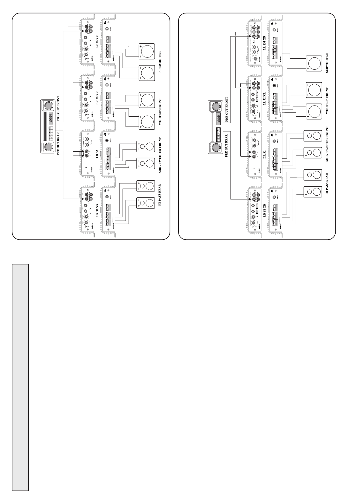
WITH FADER
SUBWOOFER MONO
THREE - WAY FRONT SYSTEM, REAR WITH FADER AND
THREE - WAY FRONT SYSTEM PLUS SUBWOOFER AND REAR
19
ITALIANO
CARATTERISTICHE
LR 52 XR: Amplificatore stereo di dimensioni compatte e dalle elevate caratteristi-
che musicali. I tratti fondamentali della sofisticata circuitazione sono: stadi "FRONT
END" realizzati con due stadi differenziali complementari, stadi finali costituiti da
transistors in connessione Darlington, transistors finali con capacità in corrente pari
a 15A ed alimentatore PWM a MOSFET dall'elevata riserva di energia.
L'amplificatore è provvisto di:
- Un CROSSOVER elettronico interno a regolazione lineare a due vie che possono
essere configurate ciascuna sulle uscite di potenza o sulle uscite preamplificate per
mezzo di uno switch.
- Uno switch per il funzionamento MONO/STEREO.
PRECAUZIONI
· Per un buon funzionamento dell'apparecchio è importante accertarsi che la tempe-
ratura nel luogo dove esso è installato sia compresa tra 0°C e 55°C.
· Il luogo prescelto per l'installazione deve essere ben ventilato ed asciutto.
· La tensione di alimentazione è di 12 VCC con negativo a massa. Accertarsi che le
caratteristiche dell'impianto elettrico del veicolo siano adatte per questo apparecchio.
· Per una maggiore sicurezza di guida si consiglia l'ascolto ad un livello tale da non
coprire i suoni provenienti dall'esterno dell'auto.
INSTALLAZIONE
Il fissaggio si effettua mediante il serraggio nelle apposite sedi delle 4 viti e relativi
distanziali in dotazione. Per un'ottima riuscita dell'impianto si consiglia di usare i
prodotti della linea audison cable che comprendono: cavi di alimentazione, di
segnale, per altoparlanti, connettori RCA e tutti gli accessori per il completamento
del cablaggio.
AVVERTENZE
· INGRESSI: Nell'eventualità che il radioriproduttore non avesse in comune la massa
di uscita con il telaio si dovrà collegare la calza del cavo schermato con il telaio del
radioriproduttore.
· USCITE: Non collegare in alcun caso tra loro oppure a massa le uscite -R e -L. Nel
caso si utilizzi un filtro crossover accertarsi che esso non abbia la massa in comune
tra i canali.
· REGOLAZIONI: Nel caso si udissero fenomeni di saturazione a livelli di volume
non elevato, significa che il segnale esce distorto dal radioriproduttore. Portare il
2
controllo di volume del radioriproduttore verso un livello più basso fino alla
scomparsa della distorsione. Regolare successivamente i livelli di taratura dell'am-
plificatore fino ad udire lievi fenomeni di saturazione.
Page 3
ENGLISH
FEATURES
LR 52 XR: stereo amplifier with compact dimensions and high musical performances.
The outstanding features of its sophisticated circuitry are: "FRONT END" stages
realized by two complementary differential stages, final stages made of transistors
in Darlington connection, final transistors with current capacity of 15 A and
MOSFET PWM power supply with a high energy reserve.
This amplifier has:
- An internal electronic CROSSOVER with two-way linear adjustment; each of
these ways can be selected on the power outputs or on the preamplified outputs
through a switch.
- A switch for MONO/STEREO functioning.
PRECAUTIONS
· In order for this device to function properly it's important that it is installed in a spot
where temperature doesn't fall below 0° C (32° F) or rise above 55° C (131° F).
· It must be installed in a dry and well ventilated spot.
· Power supply voltage is 12 VCC with negative to ground. Make sure that the
characteristics of the vehicle electrical system are compatible with this device.
· For safe driving we advise to listen to music at a volume level that won't drown
external traffic sounds.
INSTALLATION
For mounting use 4 self-threading screws and protective plastic rings provided. For
a very good result we suggest to use audison cable products to complete your
installation. These include: power cables, signal cables, speaker wires, RCA
connectors and all accessories needed to complete the wiring.
WARNINGS
· INPUTS: If the radio-cassette player doesn't share the output GND with the
chassis, the braided shield of the shielded cable must be connected to the radio-
cassette player chassis.
· OUTPUTS: Never connect -R and -L outputs to ground or to each other. If a
crossover filter is used, be sure its two channels don't have a common ground.
· REGULATIONS: If you hear saturation phenomena at moderate volume levels,
3
it means that a distorted signal is coming from the radio-cassette player.
Turn radio-cassette player volume down until there's no longer any distortion.
Then adjust the amplifier calibration levels until you hear slight saturation phenomena.
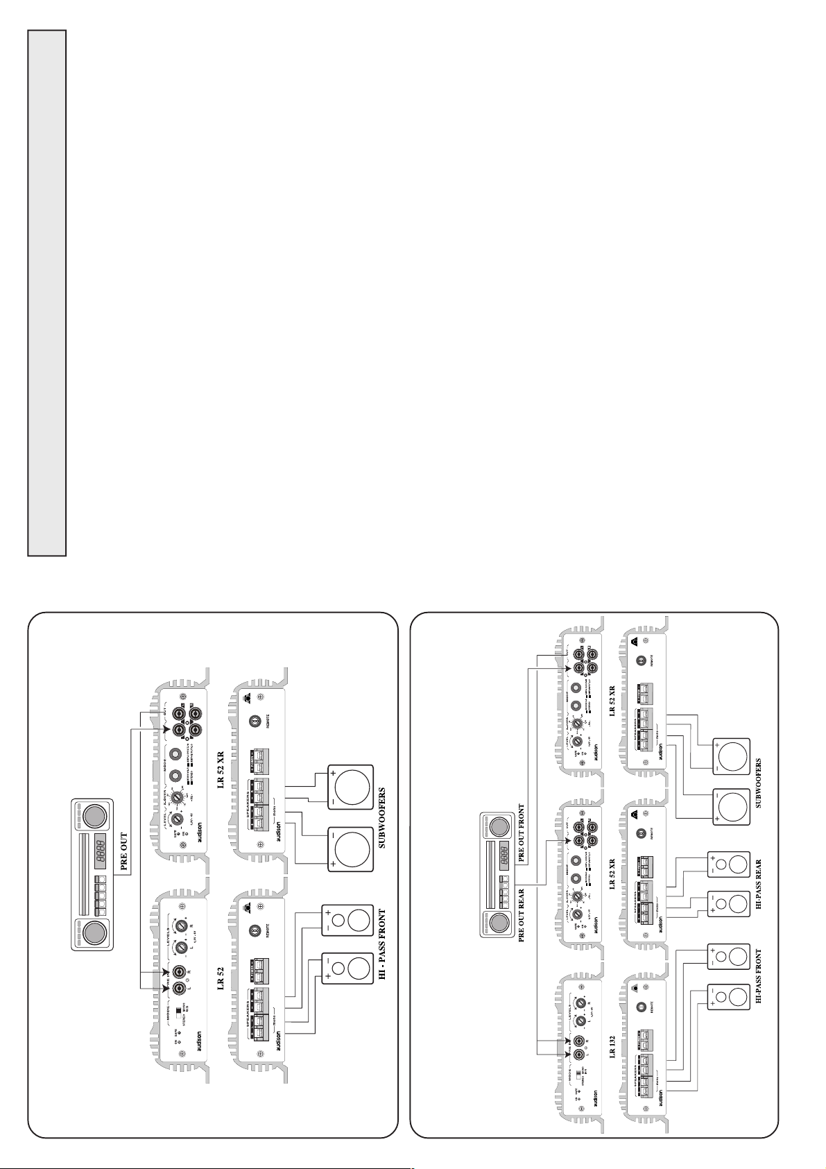
ACTIVE FRONT SYSTEM
18
ACTIVE FRONT - REAR SYSTEM WITH FADER
Page 4

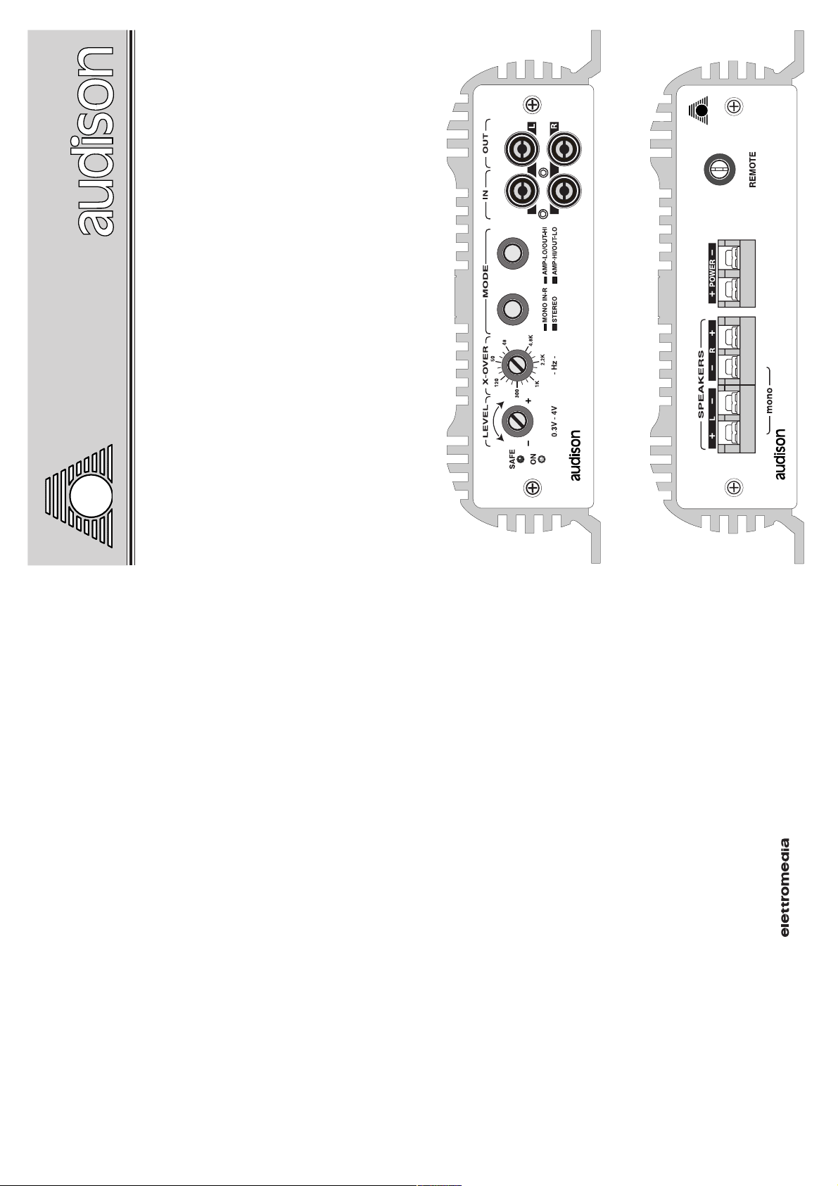
IN
REMOTE
Réglage d’activation
pour l’amplificateur
provenant de l’auto-
radio (ou de toute
autre source avec une
sortie pour le remote
des amplificateurs).
Le voltage appliqué
doit être entre 7 et 15
VDC.
BORNES
DISPOSITION DES BORNES DE CONNECTION
BORNES DE
POWER
D'ALIMENTATION
SORTIE
Bornes d’entrée pour
L / R
Sorties de puissance
Connecter le positif
l’alimentation de
l’amplificateur.
pour les canaux Left
et Right de l'ampli.
Elles peuvent être
Le voltage doit être
et le négatif de la bat-
terie avec les polarités
indiquées.
entre 11 et 15 VDC.
sélectionnées
comme sortie LO-
PASS ou comme
sorties HI-PASS au
moyen du sélecteur
situé sur le cadran
antérieur de l'ampli.
MONO
Sorties pour la
configuration mono
en pont.
A utiliser quand l'am-
pli est positionné sur
MONO IN R au
moyen du sélecteur
situé sur le cadran
antérieur de l'ampli.
17
DEUTSCH
AUSSTATTUNG
LR 52 XR: Stereo-Endstufe mit kompakten Abmessungen und hervorragender
Wiedergabequalität. Sie besitzt eine eingebaute Aktivweiche, die speziell für den Betrieb von
Subwoofern konzipiert wurde. Die außergewöhnlichen Features von dessen hochwertigem
Schaltungsaufbau sind: Eingangsstufe (FRONT END) mit zwei komplementären
Differenzverstärkern, Leistungsstufen mit Darlington-Transistoren und einer
Strombelastbarkeit von 15 A, MosFet-Schaltnetzteil mit hohen Energiereserven.
Der Verstärker besitzt:
• Eine eingebaute Zweiweg-Aktivweiche. Jeden der beidenWege kann man per Schalter
entweder auf die Lautsprecherausgänge oder auf Cinchbuchsen mit Vorverstärker-Pegel
leiten.
• Einen Stereo / Mono-Umschalter.
VORSICHTSMAßNAHMEN
· Damit das Gerät ordnungsgemäß arbeiten kann, muß es an einem Einbauort montiert
werden, bei dem die Temperatur nicht unter 0° C sinkt und über 55° C steigt.
· Es muß an einem trockenen, gut belüfteten Ort eingebaut werden.
· Es muß an eine 12-Volt-Versorgungsspannung mit Minus an Masse angeschlossen werden.
Stellen Sie sicher, daß die Netzspannung Ihres Fahrzeugs dies Voraussetzungen erfüllt.
· Damit beim Fahren die Sicherheit nicht zu kurz kommt, empfehlen wir, den Hörpegel auf
einen Betrag zu begrenzen, der es noch zuläßt, die Verkehrsgeräusche außerhalb des
Fahrzeugs wahrzunehmen.
EINBAU
Beim Einbau sollten Sie die 4 beigelegten selbstschneidenden Schrauben und Plastik-
Schutzringe benutzen. Wenn Sie eine besonders hohe Klangqualität erreichen wollen,
empfehlen wir, die Verbindungskabel von audison cable zu verwenden. Im audison cable-
Programm sind verfügbar: Stromversorgungskabel, Cinchkabel, Lautsprecherkabel, Cinch-
Stecker und -Buchsen sowie alle Zubehörteile, die Sie benötigen, um die Verkabelung
durchzuführen.
ZUR BESONDEREN BEACHTUNG
· EINGÄNGE: Wenn die Ausgangs-Masse des Autoradios nicht an die Fahrzeugmasse
angeschlossen ist, muß das Abschirmgeflecht des Cinch-Verbindungskabels mit dem
Gehäuse des Radios verbunden werden.
·AUSGÄNGE: Verbinden Sie die Lautsprecher-Ausgänge niemals mit Masse oder
miteinander. Wenn Sie ein Lautsprechersystem mit vorgeschalteter Frequenzweiche
verwenden, stellen Sie sicher, daß die Weiche keine gemeinsame Masse für beide Kanäle
aufweist.
· EINSTELLUNGEN:Wenn Sie bei moderaten Lautstärken Verzerrungen wahrnehmen, ist
mit Sicherheit der Eingang des Verstärkers übersteuert. Drehen Sie den "Low Pass"-Regler
ganz nach links. Drehen Sie dann den Lautstärkeregler des Radios etwa auf 3/4 des
Maximums. Nun regeln sie am "Low Pass" die Lautstärke, bis leichte Verzerrungen hörbar
werden. Vorsicht! Sie sollten diese Einstellungen zügig vornehmen, da hohe Lautstärken
entstehen.
4
Page 5

FRANÇAIS
CARACTÉRISTIQUES
LR 52 XR: Ampli à deux canaux de dimensions compactes et à hautes caractéristiques
musicales.
Les éléments fondamentaux de son circuit sophistiqué sont: stades "FRONT END"
réalisés avec deux stades differentiels complémentaires, stades finals constitués de
transistors en connexion Darlington, transistors finals ayant chacun une capacité en
courant de 15 A et alimentation PWM à MOSFET avec une grande réserve d'energie.
L'amplificateur a:
- Un filtre actif électronique intérieur à réglage linéaire à deux voies.
Chaque voie peut être sélectionnée sur les sorties de puissance ou sur les sorties
préamplifiées au moyen d'un sélecteur.
- Un sélecteur pour le fonctionnement MONO/STÉRÉO.
PRÉCAUTIONS
· Pour un bon fonctionnement de l'appareil, il très important de veiller à l'installer dans
un endroit où la température ne tombe jamais au dessous de 0°C et ne dépasse jamais
55°C.
· L'installation doit se faire dans un endroit sec et bien ventilé.
· L'alimentation est de type 12 VCC avec négatif à la masse. S'assurer que les
caractéristiques de l'installation du véhicule soient indiquées pour ce type d'appareil.
· Pour une conduite sans risque, nous conseillons un niveau d'écoute ne couvrant pas
le bruit du trafic environnant.
INSTALLATION
Pour le montage utiliser les rondelles et vis fournies à cet effet. Pour un résultat
optimum il est recommandé d'utiliser les éléments de la ligne audison cable suivants:
câbles d'alimentation, câbles signal, câbles pour haut-parleurs, connecteurs RCA et
tous les accessoires complétant le branchement.
ATTENTION
· ENTRÉES: Si la masse de sortie de l'autoradio n'est pas la même que celle du
châssis, relier le fil du câble isolant au châssis de l'autoradio.
· SORTIES: Ne jamais connecter entre elles ou sur la masse les sorties -R et -L. Avant
5
d'utiliser un filtre crossover, s'assurer que les canaux n'ont pas de masse commune.
· RÉGLAGES: Si des phénomènes de saturation apparaissent à un niveau de volume
modéré, cela signifie que le signal sort distordu de l'autoradio.
En ce cas, abaisser le volume de l'autoradio jusqu'à ce que le phénomène disparaisse
et régler ensuite les niveaux de l'amplificateur.
SORTIE
PRÉAMPLIFIÉE
ENTRÉE
GÉNÉRALE
FRÉQUENCE DE
RECOUVREMENT
FONCTIONS ET RÉGLAGES
NIVEAU
RÉGLAGE DE
OUT
Sortie préamplifiée
destinée à un ampli
IN
Entrée générale de
l'ampli.
X-OVER
Réglage de la
fréquence de
LEVELS
Réglage de niveau
pour les sorties de
supplémentaire ou à
l'entrée d'un filtre
Elle peut être con-
nectée à la sortie
coupure du filtre à
l'interieur de
puissance de l'am-
pli.
actif électronique, ou
à un quelconque di-
spositif pour traiter
le signal audio au
niveau préamplifié.
préamplifiée d'une
source de signal
préamplifié ou à la
sortie d'un filtre
actif électronique.
l'appareil.
Le réglage agit en
même temps sur la
section LO-PASS
et HI-PASS du
La sensibilité varie
de 300 mV à 4 V.
Le signal disponible
a la même amplitude
que celui appliqué à
l'entrée IN.
filtre actif.
La pente est 12 dB/
Oct.
Le filtre est Butter-
worth.
AMP - HI/OUT-LO:
Il sélectionne les sorties de
puissance de l'ampli pour
la reproduction de la section
HI-PASS du filtre actif
intérieur.
La section LO-PASS est
connectée aux sorties RCA
MODE
AMP - LO/OUT-HI:
Il sélectionne les sorties de
puissance de l'ampli pour
la reproduction de la section
LO-PASS du filtre actif
intérieur.
La section HI-PASS est
connectée aux sorties RCA
CHOIX DE LA FONCTION
MODE
MONO IN R:
Il sélectionne l'ampli pour
un fonctionnement mono.
(Sorties de puissance).
Entrée utilisée: Right.
STÉRÉO:
(OUT R/L) qui peuvent
véhiculer un autre ampli ou
un filtre actif électronique.
(OUT R/L) qui peuvent
véhiculer un autre ampli ou
Il sélectionne l'ampli pour
un fonctionnement stéréo.
16
un filtre actif électronique.
ON
LUMINEUX
INDICATEURS
Il indique que l’am-
plificateur est
activé.
SAFE
Il indique l’ interven-
tion des protections
malies de sortie (pré-
en cas de surchauffe
(max 80 °C) ou ano-
sence d’un courant
continu, court-
circuit ou impédan-
ce de charge très bas-
se).
L’intervention des
protections rend
l’amplificateur
inopérant.
Mettre l’amplifica-
teur en position OFF,
éliminer le problème
et remettre en posi-
tion ON.
Page 6

REMOTE
POWER IN TERMINAL BLOCK
IN
REMOTE
Anschluß für
Schaltspannung zum
Einschalten des
Verstärkers, kommt
vom Autoradio (oder
von einem anderen
Gerät, das ebenfalls
über eine
Schaltspannung für
Verstärker verfügt).
Die Schaltspannung
muß zwischen 7 und 15
Volt Gleichspannung
betragen.
ANSCHLUßKONFIGURATIONEN
POWER
Eingangsklemmen für
die Stromversorgung
des Verstärkers.
STROMVERSORGUNG
L / R
ANSCHLÜSSE
LAUTSPRECHER-
Verbinden Sie das Plus-
Lautsprecherausgänge
für den linken und
rechten Kanal des
Verstärkers.
und Massekabel
(Minus) mit den
korrespondierenden
Klemmen am
Verstärker. Die
Sie können via
speziellem Schalter
auf der Gerätefront
zum Hochpaß-oder
Tiefpaß-Ausgang
angelegte Spannung
muß zwischen 11 und
15 Volt betragen.
MONO
programmiert
werden.
Ausgangsklemmen für
den Mono-Brücken-
Betrieb. Müssen benutzt
werden, wenn das Gerät
mittels Schalter auf der
Frontseite in den Mono-
Modus geschaltet
wurde.
15
6
Page 7

Level
PWM
Power
Supply
2.2 KOhms
10 Ohms
GND
LR
V
O
L
T
S
52 XR
21
21
To Chassis
X-OVER
CUT 12 db/Oct.
48Hz-4.8KHz
Amplifiers
L
R
STEREO MODE
SPEAKER
SPEAKER
BRIDGE MODE
SPEAKER
Lo
Hi
R
L
BLOCK DIAGRAM
OUT
AUSGANG
Ausgang auf
Vorverstärker-Pegel,
VORVERSTÄRKER
IN
die für zusätzliche
EINGANG
Eingang des
Verstärkers. Hier
wird der
Endstufen,
Aktivweichen oder
jedes andere Gerät,
das ein Signal auf
Vorverstärker-Pegel
braucht,
bereitgestellt
werden. Der Pegel an
Vorverstärker-
Ausgang einer
Signalquelle oder
einer
Aktivweiche
angeschlossen.
diesen Ausgängen
entspricht dem, der
an den IN-Eingängen
anliegt.
AMP-HI / OUT-LO:
Damit wird die Hochpaß-
Sektion der Aktivweiche auf
die Lautsprecher-Ausgänge
geschaltet.
MODE
Die Tiefpaß-Sektion ist auf die
Cinch-Ausgänge (OUT R/L)
geschaltet, die einen weiteren
7
Verstärker oder eine weitere
Aktivweiche treiben kann.
SCHALTER UND REGLER
CROSSOVER-
PEGELREGLER
ANZEIGEN
X-OVER
FREQUENZ
Wählt di
Übergangsfrequenz
LEVELS
Pegelregler für
die Lautsprecher-
ON
Leuchtet, wenn der
Verstärker
der eingebauten
Aktivweiche. Der
Regler wirkt
gleichzeitig auf
die Hoch- und
Tiefpaßsektion
Ausgänge des
Verstärkers.
Empfindlichkeit
zwischen
maximal 300 mV
und minimal 4 V
SAFE
eingeschaltet ist.
Leuchtet, wenn die
Schutzschaltungen
eingreifen: bei zu
der Weiche. Die
Flankensteilheit
des Filters beträgt
12 dB/Okt mit
Butterworth-
Typologie.
regelbar.
hoher Temperatur
(oberhalb 80° C) und
Störungen an den
Lautsprecher-
Anschlüssen
(Gleichstrom,
Kurzschluß, zu
niedrige
Lastimpedanz).
Wenn die
Schutzschaltung
eingreift, deaktiviert
FUNKTIONSWEISE
AMP-LO / OUT-HI:
Damit wird die Tiefpaß-
Sektion der Aktivweiche auf
die Lautsprecher-Ausgänge
MODE
MONO IN R:
Erlaubt den Mono-
Betrieb des Verstärkers.
Dabei wird nur rechte
sich der Verstärker.
Schalten Sie die
Anlage aus und
korrigieren Sie den
Fehler. Dann können
Sie den Verstärker
wieder einschalten.
Die Hochpaß-Sektion ist auf
geschaltet.
die Cinch-Ausgänge (OUT R/L)
geschaltet, die einen weiteren
Verstärker oder eine weitere
Aktivweiche treiben kann.
STEREO:
Eingang benutzt.
Aktiviert den Stereo-
Betrieb.
14
Page 8

IN
REMOTE
CONFIGURATION OF CONNECTING CLAMPS
Turn on control for
the amplifier coming
from radio-cassette
POWER
CLAMPS
POWER SUPPLY
OUTPUT
CLAMPS
Input clamps for the
L / R
Power outputs for
amplifier power
supply.
the Left and Right
channels of the
player (or from any
Connect the battery
amplifier.
Applied voltage must
source provided with
remote control for
the amplifiers).
be between 7 and
positive and negati-
ve according to the
indicated polarities.
Applied voltage
must be between 11
They can be selected
as LO-PASS output
or HI-PASS outputs
through the special
switch put on the
15 VDC.
and 15 VDC.
MONO
front of the amplifier.
Outputs for bridge
mono configuration.
To be used when the
amplifier is selected
in MONO IN R
configuration
through the switch
on the front panel of
the amplifier.
13
ITALIANO
DATI TECNICI
ALIMENTAZIONE 11 ÷ 15 VDC
ASSORBIMENTO A VUOTO 0,9 A
ASSORBIMENTO MAX (Pot. Nominale) 12 A
MAX DYNAMIC POWER (2 Ch x 4 Ohm) 50 W
MAX DYNAMIC POWER (1 Ch x 4 Ohm) Bridge 150 W
POTENZA NOMINALE CONT. (Toll. +10%; -5%)
2 Ch x 4 Ohm; 0,3 % THD; 12 VDC 30 W (RMS)
POTENZA OUT CONT. (2 Ch x 4 Ohm; 13,8 VDC) 35 W (RMS)
POTENZA OUT CONT. (2 Ch x 2 Ohm; 13,8 VDC) 50 W (RMS)
POTENZA OUT CONT. (1 Ch x 4 Ohm; 13,8 VDC) Bridge 100 W (RMS)
DISTORSIONE THD (1 KHz; 90% Pot. nominale) 0,07 %
BANDA PASSANTE (- 3 dB; Pot. nominale) 4 Hz ÷ 100 KHz
FREQUENZA DI CROSSOVER 48 Hz ÷ 4800 Hz
PENDENZA DI TAGLIO 12 dB Butterworth
FATTORE DI SMORZAMENTO (4 Ohm) 120
TEMPO DI SALITA 4,5 µS
RAPPORTO S/N 98 dBA
SENSIBILITA’ D’INGRESSO 0,3 ÷ 4 V RMS
GUADAGNO USCITA PRE-OUT 0 dB
IMPEDENZA D’INGRESSO 15 KOhm
IMPEDENZA DI CARICO Stereo 8 - 4 - 2 Ohm
ENGLISH
IMPEDENZA DI CARICO Mono 8 - 4 Ohm
REMOTE IN 7 ÷ 15 VDC
DIMENSIONI (BxAxL) 175 x 50 x 220 mm
TECHNICAL DATA
POWER SUPPLY 11 ÷ 15 VDC
IDLING CURRENT 0.9A
MAX CONSUMPTION (Nominal Pwr) 12 A
MAX DYNAMIC POWER (2 Ch x 4 Ohms) 50 W
MAX DYNAMIC POWER (1 Ch x 4 Ohms) Bridge 150 W
CONT. NOMINAL POWER (Tol. +10%; -5%)
2 Ch x 4 Ohms; 0.3% THD; 12 VDC 30W (RMS)
CONT. OUT POWER (2 Ch x 4 Ohms; 13.8 VDC) 35W (RMS)
CONT. OUT POWER (2 Ch x 2 Ohms; 13.8 VDC) 50W (RMS)
CONT. OUT POWER (1 Ch x 4 Ohms; 13.8 VDC) Bridge 100 W (RMS)
DISTORTION THD (1 Khz; 90% Nominal Pwr) 0.07 %
BANDWIDTH (-3 dB; Nominal Pwr) 4 Hz ÷ 100 KHz
CROSSOVER FREQUENCY 48 Hz ÷ 4800 Hz
FILTER SLOPE 12 dB/oct. Butterworth
DAMPING FACTOR (4 Ohms) 120
RISE TIME 4.5 µS
SIGNAL / NOISE RATIO 98 dBA
INPUT SENSITIVITY 0.3 ÷ 4 V RMS
PRE OUT GAIN 0 dB
INPUT IMPEDANCE 15 KOhms
LOAD IMPEDANCE Stereo 8 - 4 - 2 Ohms
LOAD IMPEDANCE Mono 8 - 4 Ohms
REMOTE IN 7 ÷ 15 VDC
DIMENSIONS (WxHxL) 175 x 50 x 220 mm (6.88 x 1.96 x 8.66 inch)
8
Page 9

9
DEUTSCH
TECHNISCHE DATEN
NETZTEIL 11 ÷ 15 VDC
RUHESTROM 0,9 A
MAXIMALER STROMVERBRAUCH (bei Nennleistung) 12 A
MAX DYNAMIC POWER (2 Kan. je 4 Ohm Last) 50 W
MAX DYNAMIC POWER (1 Kan. je 4 Ohm Last) Bridge 150 W
NENNLEISTUNG (Toleranz +10%; -5%)
2 Kanäl je 4 Ohm Last; 0,3 % Klirrfaktor; 12 VDC 30W (RMS)
DAUER-AUSGANGSLEIST. (2 Kan. je 4 Ohm Last; 13,8 VDC) 35W (RMS)
DAUER-AUSGANGSLEIST. (2 Kan. je 2 Ohm Last; 13,8 VDC) 50W (RMS)
DAUER-AUSGANGSLEIST. (1 Kan. je 4 Ohm Last; 13,8 VDC) Bridge 100 W (RMS)
KLIRRFAKTOR THD (bei 1 KHz; 90 % Nennleistung) 0,07 %
LEISTUNGSBANDBREITE (-3 dB; Nennleistung) 4 Hz ÷ 100 KHz
CROSSOVER FREQUENZ 48 Hz ÷ 4800 Hz
FLANKENSTEILHEIT 12 dB Butterworth
DÄMPFUNGSFAKTOR (4 Ohm) 120
ANSTIEGSZEIT 4,5 µS
OUTPUT
PREAMPLIFIED
STORABSTAND 98 dBA
EINGANGSEMPFINDLICHKEIT 0,3 ÷ 4 V RMS
AUSGANGSGEWINN 0 dB
OUT
Preamplified output
made for an additio-
EINGANGSIMPEDANZ 15 KOhm
LASTIMPEDANZ Stereo 8 - 4 - 2 Ohm
LASTIMPEDANZ Mono 8 - 4 Ohm
REMOTE IN 7 ÷ 15 VDC
nal amplifier, for an
electronic crossover
input or for any other
devices to treat au-
FRANÇAIS
DONNÉES TECHNIQUES
ALIMENTATION 11 ÷ 15 VDC
has the same
amplitude as the
CONSOMMATION MIN. 0,9 A
signal applied on the
IN input.
ABMESSUNGEN (BxHxT) 175 x 50 x 220 mm
dio signal at pream-
plified level.
The available signal
CONSOMMATION MAX. (Puissance Continue) 12 A
MAX DYNAMIC POWER (2 Ch x 4 Ohm) 50 W
MAX DYNAMIC POWER (1 Ch x 4 Ohm) Bridge 150 W
PUISSANCE NOMINAL CONTINUE (Toll. +10%; -5%)
2 Ch x 4 Ohm; 0,3% DHT; 12 VDC 30W (RMS)
PUISSANCE CONTINUE (2 Ch x 4 Ohm; 13,8 VDC) 35W (RMS)
PUISSANCE CONTINUE (2 Ch x 2 Ohm; 13,8 VDC) 50W (RMS)
PUISSANCE CONTINUE (1 Ch x 4 Ohm; 13,8 VDC) Bridge 110 W (RMS)
DISTORSION HARM. TOTALE (1 KHz; 90 % Puiss. Nom.) 0,07 %
BANDE PASSANTE (-3 dB; Puiss. Nom.) 4 Hz ÷ 100 KHz
FRÉQUENCES DE COUPURE 48 Hz ÷ 4800 Hz
PENTE DES FILTRES 12 dB/oct. Butterworth
COÉFFICIENT D'AMORTISSEMENT (4 Ohm) 120
TEMPS DE MONTÉE 4,5 µS
RAPPORT SIGNAL / BRUIT 98 dBA
SENSIBILITÉ D'ENTRÉE 0,3 ÷ 4 V RMS
GAIN DES SORTIES PRÉAMPLIFIÉES 0 dB
IMPÉDANCE D'ENTRÉE 15 KOhm
IMPÉDANCE DE CHARGE Stereo 8 - 4 - 2 Ohm
IMPÉDANCE DE CHARGE Mono 8 - 4 Ohm
REMOTE IN 7 ÷ 15 VDC
DIMENSIONS (BxHxL) 175 x 50 x 220 mm
CONTROLS AND FUNCTIONS
IN
INPUT
GENERAL
General input for
X-OVER
CROSSOVER
FREQUENCY
CONTROL
SENSITIVITY
LIGHTS
INDICATORS
Control of the am-
plifier internal cros-
LEVELS
Level control for
the amplifier power
ON
Lit when the am-
plifier is ON.
the amplifier.
It can be connected
to the preamplified
output of a signal
source or to an
The control acts
sover cut-off fre-
quency.
simultaneously on
Sensitivity varies
outputs.
from a maximum of
300 mV to a
SAFE
When lit, it indicates
the intervention of
electronic cross-
over output.
the crossover LO-
minimum of 4 V.
protection circuits:
Slope is equal to
PASS and HI-
PASS sections.
12 dB/oct., while
in case of overhea-
176° F) or output
ting (temperature
exceeding 80° C -
filter is Butterworth.
anomalies (presence
of continuous cur-
rent, short circuit or
dangerously low
load impedance).
When protection cir-
cuits intervene, the
FUNCTIONING
amplifier shuts
down.
Turn the amplifier
off.
When the problem
MODE
MODE
is corrected, turn the
AMP-HI/OUT-LO:
It selects the amplifier
power outputs for the re-
production of the internal
crossover HI-PASS
section. LO-PASS section
AMP-LO/OUT-HI:
It selects the amplifier
power outputs for the re-
production of the internal
crossover LO-PASS
section. HI-PASS section
MONO IN R:
It allows the mono
Only the Right input is used.
functioning of the amplifier
(power outputs).
amplifier back on.
is connected to the RCA
outputs (OUT R/L),which
can drive another ampli-
is connected to the RCA
outputs (OUT R/L), which
can drive another amplifier
STEREO:
It selects the amplifier as
fier or electronic crossover.
12
or electronic crossover.
stereo.
Page 10

IN
REMOTE
Comando di accen-
sione per l'amplifica-
tore proveniente dal-
l'autoradio (o qua-
lunque tipo di sor-
gente provvista di ap-
posita uscita per il co-
mando di remote per
gli amplificatori).
La tensione applica-
ta deve essere com-
presa fra 7 e 15 VDC.
CONFIGURAZIONE DEI MORSETTI DI COLLEGAMENTO
ALIMENTAZ.
MORSETTI DI
USCITA
MORSETTI DI
USCITA
OUT
PREAMPLIF.
POWER
Morsetti di ingresso
per l'alimentazione
dell'amplificatore.
L / R
Uscite di potenza per
i canali Left e Right
dell'amplificatore.
Uscita preamplifi-
cata destinata ad un
amplificatore sup-
plementare oppure
all'ingresso di un
Collegare il positi-
vo ed il negativo di
Possono essere
configurate come
crossover elettro-
nico o qualunque
batteria con le
polarità indicate.
La tensione applica-
ta deve essere com-
presa tra 11 e 15
uscita LO-PASS op-
pure come uscite HI-
PASS per mezzo del-
l'apposito selettore
posto sul frontale
dispositivo per il
trattamento del se-
gnale audio a livel-
lo preamplificato.
VDC.
MONO
Uscite per la confi-
dell'apparecchio.
Il segnale disponi-
bile è di ampiezza
gurazione mono a
pari a quello appli-
cato all'ingresso
IN.
ponte.
Da utilizzare quan-
do l'amplificatore è
selezionato in moda-
lità MONO IN R per
mezzo dell'apposito
selettore posto sulla
placchetta frontale
dell'amplificatore.
11
COMANDI E FUNZIONI
IN
INGRESSO
GENERALE
Ingresso generale
dell'amplificatore.
FREQUENZA
CONTROLLO DI
SEGNALAZIONI
X-OVER
DI CROSSOVER
Regolazione della
frequenza di taglio
LEVELS
SENSIBILITA'
Regolazione di li-
vello per le uscite
ON
LUMINOSE
Indica l'accensione
dell'amplificatore.
Può essere collega-
to all'uscita pream-
plificata di una sor-
gente di segnale pre-
amplificata oppure
del crossover inter-
no all'apparecchio.
La regolazione agi-
sce contemporanea-
mente sulla sezione
La sensibilità va-
di potenza dell'am-
plificatore.
ria da un massimo
di 300 mV ad un
SAFE
Indica l'intervento
delle protezioni:
temperatura ecces-
all'uscita di un cross-
over elettronico.
LO-PASS e sulla
sezione HI-PASS
del crossover.
La pendenza è pari
a 12 dB/Oct. men-
minimo di 4 V.
anomalie di uscita
(presenza di corren-
te continua, corto-
siva (80°C max) o
circuito o impeden-
tre la tipologia del
filtro è Butterworth.
L'intervento della
za del carico perico-
losamente bassa).
protezione rende
inoperativo l'ampli-
AMP-HI/OUT-LO:
Predispone le uscite di po-
tenza dell'amplificatore per
la riproduzione della sezio-
MODE
AMP-LO/OUT-HI:
Predispone le uscite di po-
tenza dell'amplificatore per
la riproduzione della sezio-
MODALITA' DI FUNZIONAMENTO
MODE
MONO IN R:
Permette il funzionamento
in mono dell'amplificatore
Spegnere l'amplifi-
ficatore.
catore, rimuovere
la causa dell'anoma-
lia e quindi riaccen-
dere l'apparecchio.
La sezione LO-PASS vie-
ne HI-PASS del crossover
interno.
ne collegata alle uscite
ne LO-PASS del crossover
interno.
La sezione HI-PASS viene
collegata alle uscite RCA
(uscite di potenza).
Il solo ingresso abilitato è il
Right.
RCA (OUT R/L) disponi-
bili per pilotare un secon-
do amplificatore o crosso-
(OUT R/L) disponibili per
pilotare un secondo ampli-
ficatore o crossover elet-
STEREO:
Configura l'amplificatore in
stereo.
ver elettronico.
10
tronico.
 Loading...