

Page 1
MODE D'EMPLOI
BEDIENUNGSANLEITUNG
LR 32
Amplificateur de puissance pour l'automobile
OWNER'S MANUAL
MANUALE D'USO
Amplificatore di potenza per auto Auto Hi Fi Endstufen
Car power amplifier
PRINTED IN ITALY - Code 10125100
Power measures taken according to audison standard 1995 edition.
- 12 VDC and 13.8 VDC
- 1 KHz or crossover cut-off frequency
- 0.3 % THD
- Tolerance: +10 %; -5 %
- Continuous power given by RMS Voltage measured on resistive load
with a 4 Ohms load and with all channels in function.
- The nominal power of the amplifier is measured upon a battery voltage of 12 Volts
Strada Regina Km 3,5 • I 62018 Potenza Picena (MC) • Tel.0733/870.870 • Fax 0733/870.880 • http://www.audison.com
Page 2

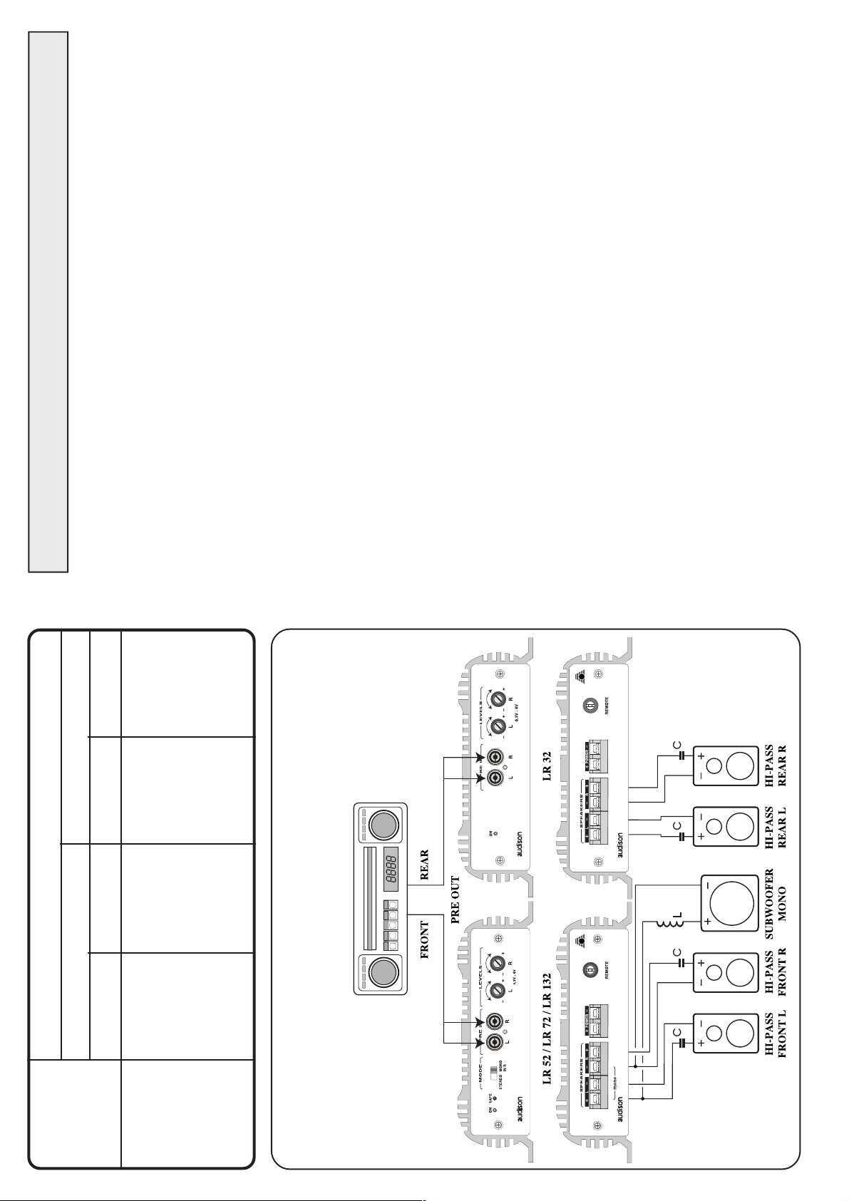
15
LR 32
STEREO SYSTEM
STEREO FRONT PLUS REAR
LR 32
2
ITALIANO
CARATTERISTICHE
La compattezza dell' LR 32, voluta per praticità d'installazione, non ha pregiudicato le
sue prestazioni che, anzi, sono state spinte ai limiti possibili per questo amplificatore.
Infatti, l'utilizzo di un circuito stampato in vetronite a doppia faccia metalizzato, la cura
del lay-out interno, l'uso di connessioni placcate oro, l'elevato grado d'industrializza-
zione dimostrano l'importanza riservata all'aspetto qualità ed affidabilità.
Lo stadio finale è capace di elevate correnti che consentono un ottimo funzionamento
anche con soli 2 Ohm di carico rendendolo estremamente versatile anche su impianti
complessi.
Inoltre, l'ampia dotazione di protezioni, il muting automatico per l'eliminazione del
classico "bump" all'accensione, l'elevata sensibilità di ingresso regolata da comandi
separati, consentono affidabilità nell'installazione, garantendo l'ottima riuscita dell'im-
pianto in auto.
PRECAUZIONI
· Per un buon funzionamento dell'apparecchio è importante accertarsi che la tempera-
tura nel luogo dove esso è installato sia compresa tra 0°C e 55°C.
· Il luogo prescelto per l'installazione deve essere ben ventilato ed asciutto.
· La tensione di alimentazione è di 12 VCC con negativo a massa. Accertarsi che le
caratteristiche dell'impianto elettrico del veicolo siano adatte per questo apparecchio.
· Per una maggiore sicurezza di guida si consiglia l'ascolto ad un livello tale da non
coprire i suoni provenienti dall'esterno dell'auto.
INSTALLAZIONE
Il fissaggio si effettua mediante il serraggio nelle apposite sedi delle 2 viti e relativi
distanziali in dotazione.
Per un'ottima riuscita dell'impianto si consiglia di usare i prodotti della linea audison
cable che comprendono: cavi di alimentazione, di segnale, per altoparlanti, connettori
RCA e tutti gli accessori per il completamento del cablaggio.
AVVERTENZE
· INGRESSI: Nell'eventualità che il radioriproduttore non avesse in comune la massa
di uscita con il telaio si dovrà collegare la calza del cavo schermato con il telaio del
radioriproduttore.
· USCITE: Non collegare in alcun caso tra loro oppure a massa le uscite -R e -L. Nel
caso si utilizzi un filtro crossover accertarsi che esso non abbia la massa in comune tra
i canali.
· REGOLAZIONI: Nel caso si udissero fenomeni di saturazione a livelli di volume non
elevato, significa che il segnale esce distorto dal radioriproduttore. Portare il controllo
di volume del radioriproduttore verso un livello più basso fino alla scomparsa della
distorsione. Regolare successivamente i livelli di taratura dell'amplificatore fino ad
udire lievi fenomeni di saturazione.
Page 3
ENGLISH
).
131°F
) or rise above 55° C (
32°F
3
FEATURES
LR 32 compact dimensions,which make its installation easier, haven't affected its
performances which are really extraordinary, beyond measure.
The high importance given to quality and reliability is shown by the use of a double
face, metalized printed circuit in FR4 (epoxy-glass), by the internal lay-out, by the
gold plated connections and the high industrialization level.
The final stage can supply high currents, which allow an excellent functioning also
with 2 Ohms load; this makes it extremely suitable for complex installations, too.
Protection supplied, automatic muting to eliminate "bump" when the system is
turned on, high input sensitivity adjusted through separate switches, allow to have
a reliable installation and a really good system.
µF)
330
245
200
165
132
100
8 Ohms
8.5
265
6.4
200
LR 32
21.0
15.9
12.7
10.6
660
495
400
330
LOUDSPEAKERS IMPEDANCE
4 Ohms
PRECAUTIONS
· In order for this device to function properly it's important that it is installed in a
spot where temperature doesn't fall below 0° C (
· It must be installed in a dry and well ventilated spot.
· Power supply voltage is 12 VCC with negative to ground. Make sure that the
characteristics of the vehicle electrical system are compatible with this device.
· For safe driving we advise to listen to music at a volume level that won't drown
external traffic sounds.
INSTALLATION
For mounting use 2 self-threading screws and protective plastic rings provided. For
a very good result we suggest to use audison cable products to complete your
installation. These include: power cables, signal cables, speaker wires, RCA
connectors and all accessories needed to complete the wiring.
WARNINGS
· INPUTS: If the radio-cassette player doesn't share the output GND with the
chassis, the braided shield of the shielded cable must be connected to the radio-
cassette player chassis.
· OUTPUTS: Never connect -R and -L outputs to ground or to each other. If a
crossover filter is used, be sure its two channels don't have a common ground.
· REGULATIONS: If you hear saturation phenomena at moderate volume levels,
it means that a distorted signal is coming from the radio-cassette player.
Turn radio-cassette player volume down until there's no longer any distortion.
Then adjust the amplifier calibration levels until you hear slight saturation
phenomena.
14
7.9
10.6
L (mH) C (µF) L (mH) C (
60
Hertz
80
FREQUENCY
6.4
100
5.3
120
4.3
150
3.2
FRONT, REAR AND SUBWOOFER PASSIVE SYSTEM
200
Page 4

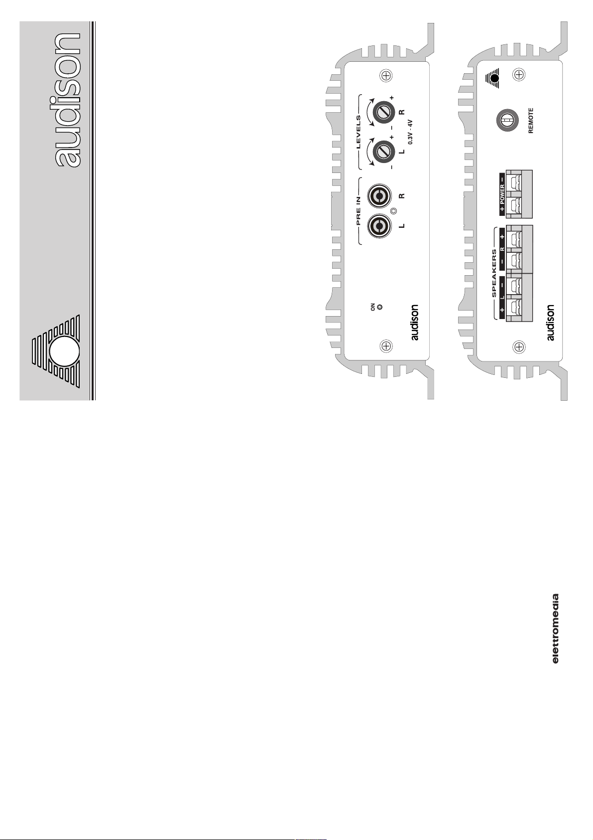
LEVELS
IN
REMOTE
RÉGLAGE DE NIVEAU
ENTRÉES
FONCTIONS ET RÉGLAGE
LUMINEUX
INDICATEUR
Réglage de niveau de la sortie de
l'ampli.
La sensibilité varie de 300 mV à
4 V.
PRE IN
Entrées Left et Right de l'ampli.
Elles peuvent être utilisées pour amplifier la sortie
PRE d'une source de signal (radio, CD) ou celle d'un
filtre actif électronique ou d'un quelconque modèle
de signal à étage préamplifié.
DISPOSITION DES BORNES DE CONNECTION
ON
Il indique que
l'amplificateur
est activé.
Réglage d'activation pour
l'amplificateur provenant de l'au-
toradio (ou de toute autre source
avec une sortie pour le remote des
BORNES
POWER
D'ALIMENTATION
Borne d'entrée pour l'alimenta-
Connecter le positif et le négatif
tion de l'amplificateur.
de la batterie avec les polarités
L / R
BORNES DE SORTIE
Sorties de puissance pour les
canaux Left et Right de l'ampli.
Connecter les hautparleurs selon
les polarités indiquées.
amplificateurs). Le voltage
appliqué doit être entre 7 et 15
VDC.
13
Le voltage doit être entre 11 et 15
indiquées.
VDC.
La connection mono en pont ou
tri-mode est impossible.
DEUTSCH
AUSSTATTUNG
Die kompakten Abmessungen des LR 32, die den Einbau einfacher machen, haben die
Qualitäten, die außerordentlich und mit Messungen allein gar nicht zu erfassen sind, nicht im
geringsten beeinflußt. Der hohe Stellenwert, der der Produktqualität und der Zuverlässigkeit
beigemessen wurde, zeigt sich in der Benutzung der doppelseitigen, metallisierten Platine in
FR4-Technik (Fiberglas-Material), im inneren Aufbau, den goldbeschichteten Anschlüssen
und in der hohen Fertigungsqualität.
Die Endstufe kann sehr hohe Ströme liefern, was einen exzellenten Betrieb an 2-Ohm-Lasten
erlaubt; das macht den LR 32 extrem brauchbar auch für komplexe Installationen.
Die eingebauten Schutzschaltungen, das automatische Muting zur Vermeidung von
Einschaltknacken und die hohe Eingangsempfindlichekeit, die durch separate Schalter justiert
wird erlauben den Aufbau einer zuverlässigen Installation und eine wirklich gute Anlage.
VORSICHTSMAßNAHMEN
· Damit das Gerät ordnungsgemäß arbeiten kann, muß es an einem Einbauort montiert werden,
bei dem die Temperatur nicht unter 0° C sinkt und über 55° C steigt.
· Es muß an einem trockenen, gut belüfteten Ort eingebaut werden.
· Es muß an eine 12-Volt-Versorgungsspannung mit Minus an Masse angeschlossen werden.
Stellen Sie sicher, daß die Netzspannung Ihres Fahrzeugs dies Voraussetzungen erfüllt.
· Damit beim Fahren die Sicherheit nicht zu kurz kommt, empfehlen wir, den Hörpegel auf
einen Betrag zu begrenzen, der es noch zuläßt, die Verkehrsgeräusche außerhalb des
Fahrzeugs wahrzunehmen.
EINBAU
Beim Einbau sollten Sie die 2 beigelegten selbstschneidenden Schrauben und Plastik-
Schutzringe benutzen. Wenn Sie eine besonders hohe Klangqualität erreichen wollen,
empfehlen wir, die Verbindungskabel von audison cable zu verwenden. Im audison cable-
Programm sind verfügbar: Stromversorgungskabel, Cinchkabel, Lautsprecherkabel, Cinch-
Stecker und -Buchsen sowie alle Zubehörteile, die Sie benötigen, um die Verkabelung
durchzuführen.
ZUR BESONDEREN BEACHTUNG
· EINGÄNGE: Wenn die Ausgangs-Masse des Autoradios nicht an die Fahrzeugmasse
angeschlossen ist, muß das Abschirmgeflecht des Cinch-Verbindungskabels mit dem Gehäuse
des Radios verbunden werden.
·AUSGÄNGE: Verbinden Sie die Lautsprecher-Ausgänge niemals mit Masse oder miteinander.
Wenn Sie ein Lautsprechersystem mit vorgeschalteter Frequenzweiche verwenden, stellen
4
Sie sicher, daß die Weiche keine gemeinsame Masse für beide Kanäle aufweist.
· EINSTELLUNGEN:Wenn Sie bei moderaten Lautstärken Verzerrungen wahrnehmen, ist
mit Sicherheit der Eingang des Verstärkers übersteuert. Drehen Sie den "Low Pass"-Regler
ganz nach links. Drehen Sie dann den Lautstärkeregler des Radios etwa auf
3/4 des Maximums. Nun regeln sie am "Low Pass" die Lautstärke, bis leichte Verzerrungen
hörbar werden. Vorsicht! Sie sollten diese Einstellungen zügig vornehmen, da hohe
Lautstärken entstehen.
Page 5

FRANÇAIS
CARACTÉRISTIQUES
Les dimensions réduites du LR 32, voulues pour une plus grande facilité d'installation,
ne portent aucun préjudice à ses performances qui, au contraire, ont été ici poussées à
leur maximum. En effet, l'utilisation d'un circuit imprimé en vétronite à double face
métalisé, les soins portés au lay-out, l'utilisation de connections plaquées or, le degré
élevé d'industrialisation démontrent l'importance accordée à l'aspect qualité-fiabilité.
Le stade final supporte facilement hauts courants qui permettent un fonctionnement
optimal avec seulement 2 Ohm de charge, le rendant trés versatile, même sur des
installations particulièrement complexes.
En outre, les nombreuses protections dont le système est doté, le muting automatique
pour l'élimination de l'habituel "bump" à l'allumage, la sensibilité élevée d'entrée réglée
par des boutons séparés révèlent la fiabilité de l'appareil et garantissent la réussite
exceptionnelle de son installation dans la voiture.
PRÉCAUTIONS
· Pour un bon fonctionnement de l'appareil, il très important de veiller à l'installer dans
un endroit où la température ne tombe jamais au dessous de 0° C et ne dépasse jamais
55° C.
· L'installation doit se faire dans un endroit sec et bien ventilé.
· L'alimentation est de type 12 VCC avec négatif à la masse. S'assurer que les
5
caractéristiques de l'installation du véhicule soient indiquées pour ce type d'appareil.
· Pour une conduite sans risque, nous conseillons un niveau d'écoute ne couvrant pas
le bruit du trafic environnant.
INSTALLATION
Pour le montage utiliser les rondelles et vis fournies à cet effet. Pour un résultat
optimum il est recommandé d'utiliser les éléments de la ligne audison cable suivants:
câbles d'alimentation, câbles signal, câbles pour haut-parleurs, connecteurs RCA et
tous les accessoires complétant le branchement.
ATTENTION
· ENTRÉES: Si la masse de sortie de l'autoradio n'est pas le même que celle du châssis,
relier le fil du câble isolant au châssis de l'autoradio.
·SORTIES: Ne jamais connecter entre elles ou sur la masse les sorties -R et -L.
Avant d'utiliser un filtre crossover, s'assurer que les canaux n'ont pas de masse
commune.
· RÉGLAGES: Si des phénomènes de saturation apparaissent à un niveau de volume
modéré, cela signifie que le signal sort distordu de l'autoradio.
En ce cas, abaisser le volume de l'autoradio jusqu'à ce que le phénomène disparaisse et
régler ensuite les niveaux de l'amplificateur.
SCHALTER UND REGLER
LEVELS
PEGELREGLER
Pegelregler für die Lautsprecher-
Ausgänge des Verstärkers.
Empfindlichkeit zwischen 300
PRE IN
EINGÄNGE
Linker und rechter Eingäng des Verstärkers. Hier wird
der Vorverstärker-Ausgang einer Signalquelle (Auto-
radio mit Cassette, CD oder DAT), einer Aktivweiche
ON
ANZEIGE
Leuchtet, wenn
der Verstärker
eingeschaltet ist.
mV und 4 V regelbar.
ANSCHLUßKONFIGURATION
oder jedes anderen Typs von Signalprozessor auf
Vorverstärkerpegel angeschlossen.
IN
REMOTE
Anschluß für Schaltspannung zum
Einschalten des Verstärkers, kommt
vom Autoradio (oder von einem
anderen Gerät, das ebenfalls über
eine Schaltspannung für Verstärker
verfügt). Die Schaltspannung muß
zwischen 7 und 15 Volt
Gleichspannung betragen.
POWER
STROMVERSORGUNG
Eingangsklemmen für die
Verbinden Sie das Plus-und
Stromversorgung des Verstärkers.
Massekabel (Minus) mit den
korrespondierenden Klemmen am
Verstärker. Die angelegte Spannung
muß zwischen 11 und 15 Volt
betragen.
L / R
Lautsprecherausgänge für den
linken und rechten Kanal des
Verstärkers. Verbinden Sie die
Lautsprecher entsprechend
der abgebildeten Polaritäten.
Ein Mono-Brückenbetrieb
und eine Beschaltung im Tri-
LAUTSPRECHERANSCHLÜSSE
Mode ist nicht möglich.
12
Page 6

CONTROLS AND FUNCTIONS
LEVELS
LEVEL CONTROLS
Level control for the amplifier
Left and Right outputs.
Sensitivity varies from 300 mV
to 4 V.
PRE IN
INPUTS
Left and Right inputs of the amplifier.
They can be used to amplify the PRE output of a
signal source (radio, CD-DAT), an electronic cross-
over output or an output of any kind of signal
processor at preamplified level.
IN
REMOTE
Turn on control for the amplifier
coming from radio-cassette player
(or from any sources provided with
remote control for amplifiers).
Applied voltage must be between
7 and 15 VDC.
POWER
POWER SUPPLY CLAMPS
Input clamps for the amplifier
Connect the battery positive and
power supply.
negative according to indicated
Applied voltage must be between
polarities.
11 and 15 VDC.
11
ON
LIGHT
INDICATOR
Lit when the
amplifier is on.
CONFIGURATION OF CONNECTING CLAMPS
L / R
OUTPUT CLAMPS
Power outputs for the Left and
Right channels of the amplifier.
Connect loudspeakers accor-
ding to indicated polarities.
Bridge mono or tri mode
connection is not possible.
6
Page 7

BLOCK DIAGRAM
Left
Levels
Right
Levels
10 Ohms
To Chassis
Pre
GND
Decoupler
7
COMANDI E FUNZIONI
LEVELS
CONTROLLI DI LIVELLO
Regolazioni di livello per le usci-
te Left e Right dell'amplificato-
re. La sensibilità varia da 300
mV a 4 V.
PRE IN
INGRESSI
Ingressi Left e Right dell'amplificatore.
Possono essere utilizzati per amplificare l'uscita
PRE di una sorgente di segnale (autoradio, lettore
CD-DAT) oppure l'uscita di un crossover elettronico
o di un qualunque tipo di processore di segnale a
livello preamplificato.
ON
LUMINOSA
SEGNALAZIONE
Indica l'accen-
sione dell'ampli-
ficatore.
CONFIGURAZIONE DEI MORSETTI DI COLLEGAMENTO
IN
REMOTE
Comando di accensione per l'am-
plificatore proveniente dall'auto-
radio (o qualunque tipo di sorgente
provvista di apposita uscita per il
comando di remote per gli amplifi-
POWER
MORSETTI DI
ALIMENTAZIONE
Morsetti di ingresso per l'alimen-
Collegare il positivo ed il negati-
tazione dell'amplificatore.
vo di batteria secondo le polarità
indicate. La tensione applicata deve
L / R
MORSETTI DI USCITA
Uscite di potenza per i canali
Left e Right dell'amplificatore.
Collegare gli altoparlanti secon-
do le polarità indicate.
Il collegamento mono a ponte o
catori). La tensione applicata deve
essere compresa fra 7 e 15 VDC.
10
essere compresa tra 11 e 15 VDC.
tri-mode non é possibile.
Page 8

9
DEUTSCH
TECHNISCHE DATEN
NETZTEIL 11 ÷ 15 VDC
RUHESTROM 0,3 A
MAXIMALER STROMVERBRAUCH (bei Nennleistung) 5 A
MAX DYNAMIC POWER (4 Kan. je 4 Ohm Last) 30 W
NENNLEISTUNG (Toleranz +10 %; -5 %)
2 Kanäle je 4 Ohm Last; 0,3 % Klirrfaktor; 12 VDC 14 W (RMS)
DAUER-AUSGANGSLEIST. (2 Kan. je 4 Ohm Last; 13,8 VDC) 20 W (RMS)
DAUER-AUSGANGSLEIST. (2 Kan. je 2 Ohm Last; 13,8 VDC) 32 W (RMS)
KLIRRFAKTOR THD (bei 1 KHz; 90 % Nennleistung) 0,07 %
LEISTUNGSBANDBREITE (-3 dB; Nennleistung) 7 Hz ÷ 100 KHz
DÄMPFUNGSFAKTOR (4 Ohm) 220
ANSTIEGSZEIT 4,5 µS
STÖRABSTAND 98 dBA
EINGANGSEMPFINDLICHKEIT 0,3 V ÷ 4 VRMS
EINGANGSIMPEDANZ 15 KOhm
LASTIMPEDANZ 8 - 4 - 2 Ohm
REMOTE IN 7 ÷ 15 VDC
ABMESSUNGEN (BxHxT) 175 x 50 x 90 mm
FRANÇAIS
DONNÉES TECHNIQUES
ALIMENTATION 11 ÷ 15 VDC
CONSOMMATION MIN. 0,3 A
CONSOMMATION MAX. (Puissance Nominal) 5 A
MAX DYNAMIC POWER (2 Ch x 4 Ohm) 30 W
PUISSANCE NOMINAL CONTINUE (Toll. +10 %; -5 %)
2 Ch x 4 Ohm; 0,3 % THD; 12 VDC 14 W (RMS)
PUISSANCE SORTIE CON. (2 Ch x 4 Ohm; 13,8 VDC) 20 W (RMS)
PUISSANCE SORTIE CON. (2 Ch x 2 Ohm; 13,8 VDC) 32 W (RMS)
DISTORSION HARM. TOTALE (1 KHz; 90 % Puiss. Nom.) 0,07 %
BANDE PASSANTE (-3 dB; Puissance Nominal) 7 Hz ÷ 100 KHz
COÉFFICIENT D'AMORTISSEMENT (4 Ohm) 220
TEMPS DE MONTÉE 4,5 µS
RAPPORT SIGNAL/BRUIT 98 dBA
SENSIBILITÉ D'ENTRÉE 0,3 V ÷ 4 VRMS
IMPÉDANCE D'ENTRÉE 15 KOhm
IMPÉDANCE DE CHARGE 8 - 4 - 2 Ohm
REMOTE IN 7 ÷ 15 VDC
DIMENSIONS (BxHxL) 175 x 50 x 90 mm
ITALIANO
DATI TECNICI
ALIMENTAZIONE 11 ÷ 15 VDC
ASSORBIMENTO A VUOTO 0,3 A
ASSORBIMENTO MAX (Pot. Nominale) 5 A
MAX DYNAMIC POWER (2 Ch x 4 Ohm) 30 W
POTENZA NOMINALE CONT. (Toll. +10 %; -5 %)
2 Ch x 4 Ohm; 0,3 % THD; 12 VDC 14 W (RMS)
POTENZA OUT CONTINUA (2 Ch x 4 Ohm; 13,8 VDC) 20 W (RMS)
POTENZA OUT CONTINUA (2 Ch x 2 Ohm; 13,8 VDC) 32 W (RMS)
DISTORSIONE THD (1 KHz; 90 % Pot. Nominale) 0,07 %
BANDA PASSANTE (-3 dB; Pot. Nominale) 10 Hz ÷ 100 KHz
FATTORE DI SMORZAMENTO (4 Ohm) 220
TEMPO DI SALITA 4,5 µS
RAPPORTO SEGNALE RUMORE 98 dBA
SENSIBILITA' D'INGRESSO 0,3 V ÷ 4 VRMS
IMPEDENZA D'INGRESSO 15 KOhm
IMPEDENZA DI CARICO 8 - 4 - 2 Ohm
REMOTE IN 7 ÷ 15 VDC
DIMENSIONI (BxAxL) 175 x 50 x 90 mm
ENGLISH
TECHNICAL DATA
POWER SUPPLY 11 ÷ 15 VDC
IDLING CURRENT 0.3 A
MAX CONSUMPTION (Nominal Pwr) 5 A
MAX DYNAMIC POWER (2 Ch x 4 Ohms) 30 W
CONT. NOMINAL POWER (Tol. +10 %; -5 %)
2 Ch x 4 Ohms; 0.3 % THD; 12 VDC 14 W (RMS)
CONT. OUT POWER (2 Ch x 4 Ohms; 13.8 VDC) 20 W (RMS)
CONT. OUT POWER (2 Ch x 2 Ohms; 13.8 VDC) 32 W (RMS)
DISTORTION THD (1 KHz; 90 % Nominal Pwr) 0.07 %
BANDWIDTH (-3 dB; Nominal Pwr) 10 Hz ÷ 100 KHz
DAMPING FACTOR (4 Ohms) 220
RISE TIME 4.5 µS
SIGNAL / NOISE RATIO 98 dBA
INPUT SENSITIVITY 0.3 V ÷ 4 VRMS
INPUT IMPEDANCE 15 KOhms
LOAD IMPEDANCE 8 - 4 - 2 Ohms
REMOTE IN 7 ÷ 15 VDC
DIMENSIONS (WxHxD) 175 x 50 x 90 mm (6.88 x 1.96 x 3.54 inch)
8
 Loading...