

Page 1
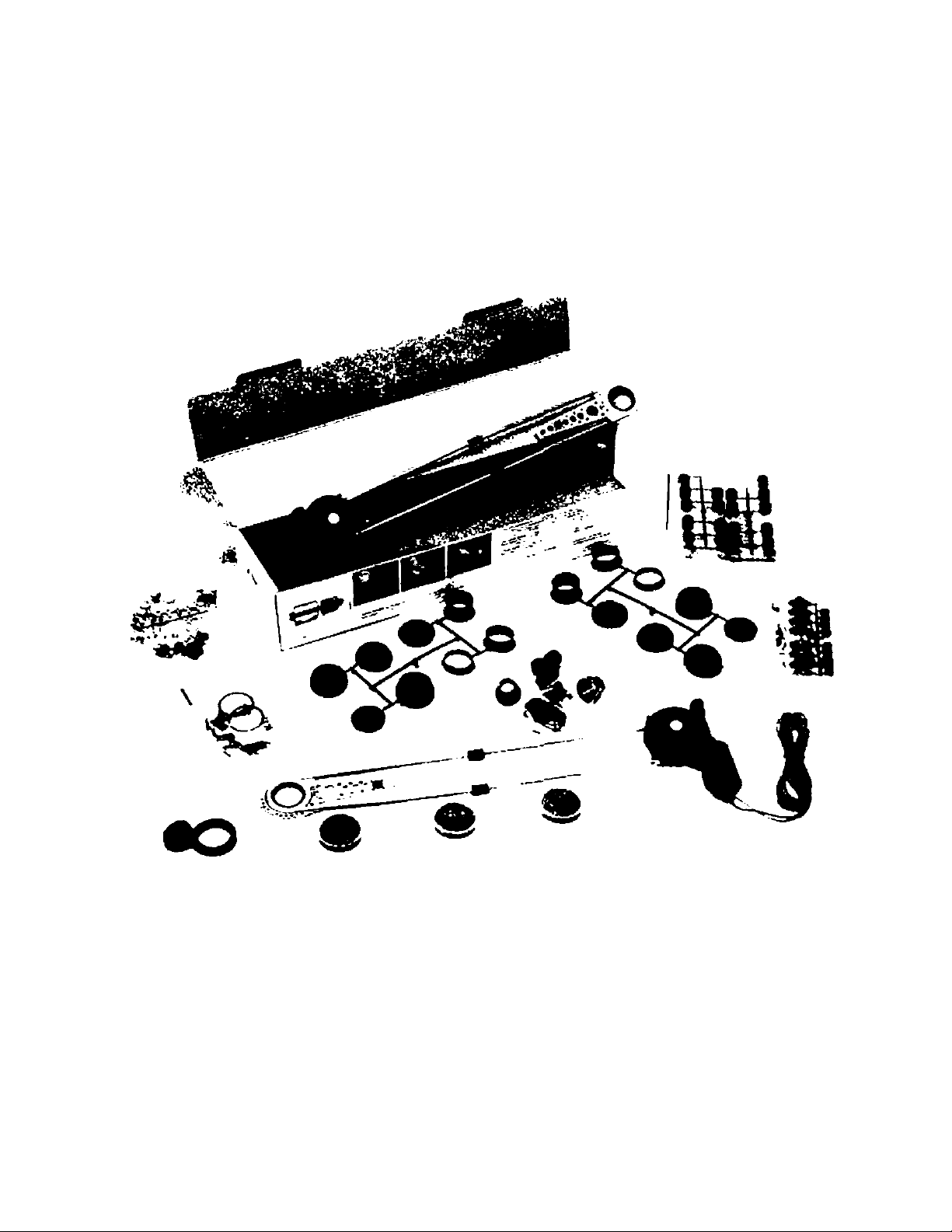
RUDIOUOX
universal power windows
MOUNTING INSTRUCTIONS
DETAILED INSTRUCTIONS FOR
MOUNTING POWER WINDOWS
ON THE U.S. CARS
Page 2
□ ’
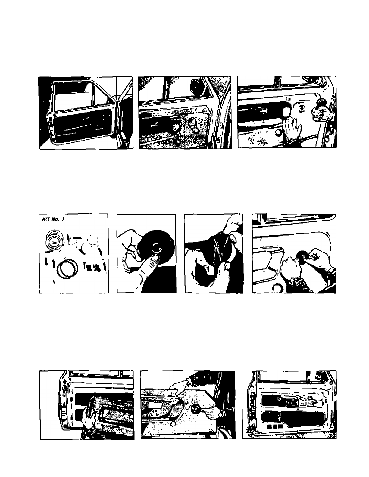
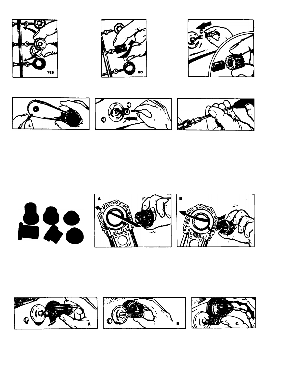
REMOVE HANDLE
FROM WINDOW REGULATOR/PIVOT
g——
APPLY CENTERING ADHESIVE TO THE PANEL
Place adhesive over pivot making sure that it adheres properly to door casing
PANEL DEMOUNTING
Remove door pane!.
f.
sure the centering adhesive is firmly applied to the panel
Page 3
B .
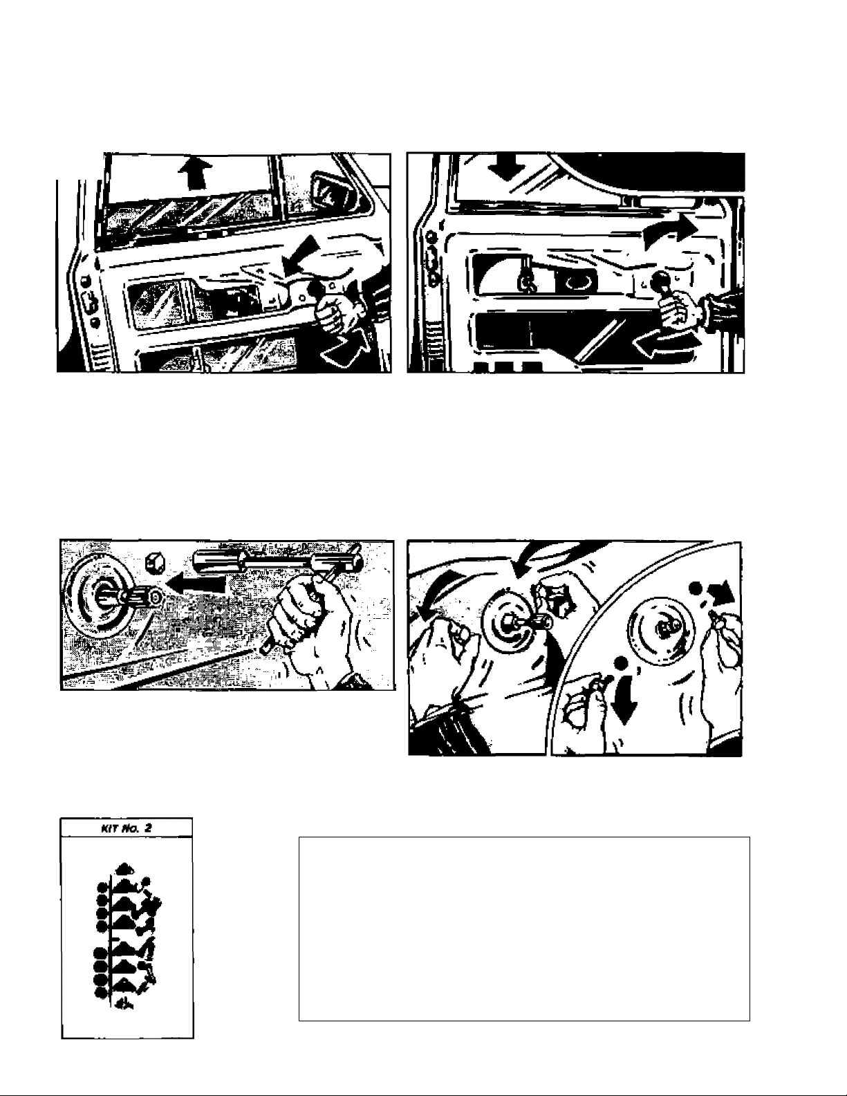
MANUALLY CHECK
THE MOVEMENT OF THE WINDOW
nw
Adjust the registers or guides if the window does not operate freely
0
OPTIONAL OPERATION:
A • IN ORDER TO USE THE SMALLEST CAP ON SOME VEHICLES, IT MAY BE NECESSARY TO
MOVE BACK THE WINDOW REGULATOR ASSEMBLY.
B - AFTER REMOVING ORIGINAL BOLTS FROM THEIR SEATS, REFER TO THE TABLE BELOW
TO CHOOSE SUITABLE SPACERS AND BOLTS (SUPPLIED IN KIT NO.
KIT NO. 2
2).
Trapezoidal spacers h. 5/16"
Trapezoidal spacers h. 3/16” Bolts h. 9/16"
Trapezoidal spacers h. 3/8”
Bolts h. 3/8”
Bolts h. 3/4”
Page 4
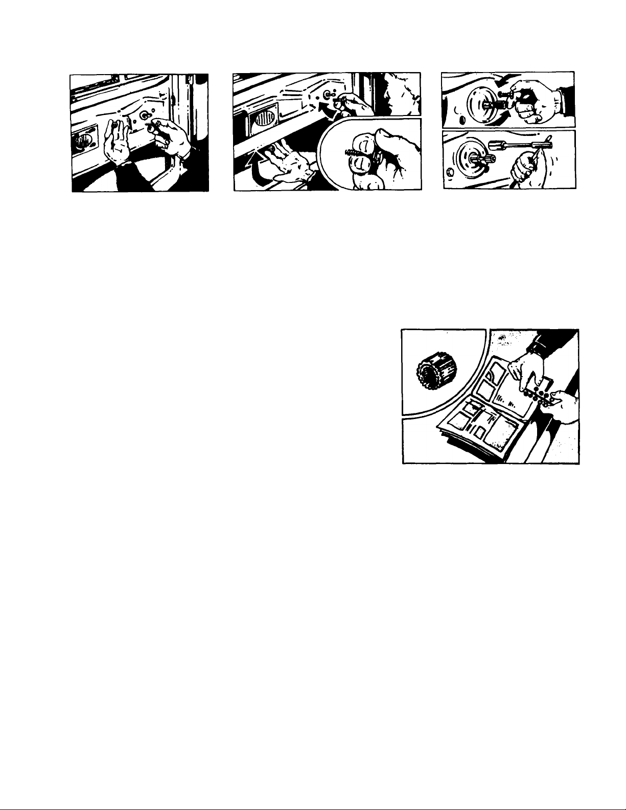
C • INSERT SPACERS BETWEEN MANUAL MECHANISM AND DOOR-PANEL
Check that the bolts of the window assembly are tight
0
FIT ADAPTOR ON REGULATOR PIVOT
iÉÉJtâÂ.
STWTfn
From Kit No. 3, choose the correct adaptor for the model of vehicle. See adaptor Table
below.
Adaptor table (Kit No. 3)
N. 1 ALFA ROMEO - AUTOBIANCHI - BEDFORD - DAF
DATSUN - FIAT - LANCIA - MERCEDES - NISSAN
OPEL - PORSCHE - SUBARU
N. 2 ARO - CITROËN - PEUGEOT - RENAULT - SEAT
TALBOT
N. 3 AUDI - BMW - FIAT - FORD (EUROPE)
PORSCHE - VOLKSWAGEN - VOLVO
N. 4 AUSTIN ROVER
N. 5 VAUXALL - JAGUAR - BEDFORD - ROVER
N. 6 FORD (UK)
N. 7 OPEL
N. 8 DAIHATSU - MITSUBISHI - TOYOTA - SUZUKI
CHEVROLET - G.M.
N. 9 HONDA
N. 10 MAZDA
N. 11 ISUZU
N. 12 FORD (U.S.A.)
N. 13 DODGE - CHRYSLER
Page 5
Take caution in removing adaptor from Kit. Do not twist-off,
If the handle is fixed with a screw, use it to fix the adaptor
0
INSERT GEAR SLEEVE
INTO THE TRANSMISSION
KIT NO. 4
Geared sleeve to be inserted towards inside of vehicle
A) Insertion from the red marked side.
B) Insertion from the opposite side of the red mark.
Gear conversion
A) Wrong: too long.
B) Wrong: too short.
C) Right: length of geared sleeve and pivot are the same.
If a standard is not available for your car, gear H = 37 should be used after cutting it to
match regulator pivot.
Page 6
0
SECURE GEAR TO THE TRANSMISSION
WITH CIRCLIP
KIT NO. 1
' Tb^V
'©
(Circlip included in KIT No
0 "
INSTALLATION OF THE ELECTRIC POWER
WINDOW MECHANISM INTO THE DOOR
Fixing or shifting of transmission bracket.
KIT NO. 5
It is possible to mount one or more brackets in pos. 1 2, 3, 4, 5, as shown above 7
Page 7

Motor may be rotated on transmission in order to
faciiitate a secure mount
©
A
A) Remove the screws.
Rotate the geared motor to the required position
C) Retighten the screws in their seats.
FASTENING OF GEARED MOTOR
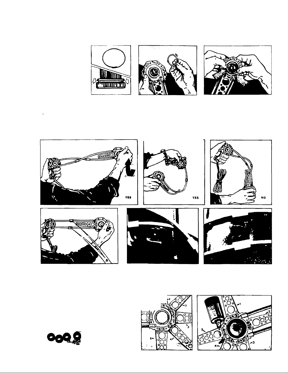
Drill door panel to hook*up springs.
IMPORTANT:
The power cable for the motor must always be positioned downwards
Fastening of geared motor with brackets
A) Fastening with two brackets,
6) Fastening with brackets and springs.
C) Fasten geared motor behind door panel with one bracket.
Page 8

Fastening of geared motor with springs
Take springs and wire clip out of KIT No 1
1) Spring,
2) Wire c!ip-
Hook up springs and lock hooks
a
APPLY PADDING TO THE GEARED MOTOR
IN CASE THE MOTOR, OR PARTS OP IT, ARE IN DIRECT CONTACT WITH ANY
METAL PARTS, THE SUPPLIED PADDING SHOULD BE USED AS SHOWN BELOW.
SS -
Page 9

POSITION AND FIX BRACKET
Position the bracket without forcing the transmission
Fasten bracket through one of the holes (Use the outer ones, where possible).
1) Internal metal bushing
2) External rubber bushing
Drill 7/64” holes to fasten bracket
1) Screw
2) Speed nut.
10
Page 10

LOCK ADAPTOR AND GEAR SLEEVE
Insert the screw in the space between the adaptor and the gear sleeve
CUT DOOR PANEL WITH SPECIAL CUTTER
DOOR PANEL CUTTER TOOL SUPPLIED UPON REQUEST
0
mm]
Center the cutter with the adhesive Tighten with a wrench until the cutter comes free
Remove any remaining adhesive.
To clean out the cutter, do as shown above
t
I
Page 11

FIX GROMMET WITH RETAINER RING
|g
Mo, 1 No. 3
No. 1 Smalt,
No. 2 Medium
No, 3 Larg
NO. 3
The grommet cap locks to panel by means of a
retainer ring
The grommet has to come through the door casing at least 5/32 in order to be locked
with the retainer ring.
To choose the proper grommet cap. follow this procedure:
— Insert grommet cap no. 1 (SMALL) into the panel, if it does not come through, try
no P (MEDIUM) and then, if necessary, no. 3 (LARGE) ’
NO. 1
10 MAJC
5/32"
Na. 1
A) No. 1 SMALL (wrong; too short).
NO 1
V»!
No. 2 MEDIUM (wrong: too short)
No. 3 LARGE (yes),
B) if the door casing is less tham 5/32" thick a perfect tit between cap and grommet can
be obtained by inserting a sponge from the rear of the door casing.
1?
Page 12

UNIVERSAL ELECTRIC WINDOWS
WITHOUT CLUTCH
ART.5S000013
0
FIT CAP ON DOOR PANEL
Fii Ihe Cap on the grommel and fit the panel on the door
NOTE!
A t B
% ^
Ho. &
When the regulator pivot does not come out from the pane! (photo A and B) you can use
cap No. 0 tor a better appearance.
__
Q_
^ n
^ n
L0_
Page 13

INSTALLATION EXAMPLE FOR ELECTRIC POWER WINDOWS * \
IN SOME CARS IN THE U.S.
BUICK CENTURY (4 Doors) front iefl
— in&sri gaar H 15 (insert trcjm red marked side)
— aclapter Me. 9
— turn tranernission aids of geared motor towards inside of car
— affix geared motor wilh springs
— grommet No, T
— cap No. 1
BUICK CENTURY (4 Doors} rear righi
” adjust bracket on transmission shortened 1“
— Ir^&erl gear H 16 finsert from red marked side)
— adapter No. 9
— turn IransmissiDn side of geared motor lowards inside of car
— affix geared motor wlh plastic lasiener
™ grommet No. 1
— cap No. 1
CHEVROLET FULL SIZE mod. ’66 front left
— insert gear H 15 (nnserl from red marked side)
^ adapl« No. 9
— turn transmission side of geared motor towards inside of car
— afllx geared motor with springs
— grommet No. 1
— cap No. 1
14
FORD MUSTANG troni righi
— adjust bracket on transmission
^ insert gear H 16 (insert from red marked side)
— adaplot No. 12
— apply paddings to geared motor
— turn transrriFssioii side of geared motur towards Inside of car
— affix geared motor with two brackets
— gnommet No. 1
— cap Ng. 1
Page 14

FORD TEMPO front right
— adjust bracket on transmission
— rotate geared motor 180° on transmission
— insert gear H 15 (insert from red marked side)
— adaptor No. 12
— apply paddings to geared motor
— turn transmission side of geared motor towards inside of car
— affix geared motor with bracket shortened 2.2”
— grommet No. 1
— cap No. 1
HONDA ACCORD front right
— adjust bracket on transmission
— insert gear H 15 (insert from red marked side)
— adaptor No. 9
— apply paddings to geared motor
— turn transmission side of geared motor towards inside of car
— affix geared motor with plastic fastener '
— grommet No. 1
— cap No. 2
* Bend door panel in area where cables cross. Affix cables to
door panel with plastic fastener.
* Care should be taken to not damage the geared motor with
door stopper
HONDA CIVIC CRX front right
— adjust bracket on transmission
— rotate geared motor 90° on transmission
— insert gear H 15 (insert from red marked side)
— adaptor No. 9
— apply paddings to grill of geared motor
— turn transmission side of geared motor towards inside of car
— affix geared motor with bracket (affix support arm screw)
— grommet No. 1
— cap No. 1
MAZDA 626 4 Doors (U.S.) mod. ’89 front right
— adjust bracket on transmission shortened 1"
— rotate geared motor 90° on transmission
— insert gear H 15 (insert from red marked side)
— adaptor No. 10
— turn transmission side of geared motor towards inside of car
— affix geared motor with two brackets after having shortened
one off 1”
— grommet No. 1
— cap No. 1
15
Page 15

MAZDA 626 4 Doors (U.S.) mod. ’89 rear nghi
—> adjust bracket on transmission and bend appropriately
— insert gear H 15 (insert from red marked side)
— adaptor No. to
— apply paddings to geared motor
— turn transmission side o( geared motor towards inside ott car
— affix geared motor vnth bracket shortened i "
— grommet No. t
— cap No. 1
PONTIAC 6000 from right
— insert gear H 37 (insert from red marked side)
— adaptor No 8
— turn transmission side o( geared motor towards inside ot car
— affix geared motor with Iwo brackets
— grommet No 1
— cap No t
PONTIAC 6000 rear right
— shorten bracket on transmission 6"
—> insert gear H 15 (insert from red marked side)
~ adaptor No. 8
— apply paddings to geared motor
— turn transmission side of geared motor towards inside of car
— affix geared motor with two bracket shortened 2.2"
— grommet No. t
— cap No, 1
PONTIAC GRAN PRIX front left
— adiusi bracket on iransniission and add a r\ew one
— insert gear H 25 (insert from red marked side)
— adaptor No. 8
^ apply paddings to geared motor
^ turn grill Side of geared motor towards inside of car
— affix geared motor with bracket shortened 2.2"
— grommet No. t
— cap No 1
Page 16

CHEVnOLET/QMC S-10/15 PJCKUP rront left
— shorlftn bratkQi on trarsmisBioo 1.6"
— gaor H 15 (insart from rad marked side)
— edaplor No. B
— apply paddings to geared motor
— lufo transmission side of geared motor towards inside of tar
— atfl* geared mo(oi with two brackets
— grommai No. 1 (may need To use with 2.9" plastit round
washer)
— cap No. 1
DODQE CARAVAN front left
— shorten bracket on iransmiaaion 1.6"
— rpiBla geared motor 9D* on transmisaion
— Inesrt gear H 1S flnsari from rod marked side)
— adaptor No. 13
— lorn trarsmiaslon side of geared motor towards inside of oar
— etfia geared motor with two brackata shodened 2.2"
— grommet No 1
— oap No. 1
FORD AEROSTAR front left
— adiLdsi bracket on transmission
— Insert gear H 15 (irisert from red marked side)
— adaptor No 12
^ turn transmission side of geared motor towards inside of car
— atfi* geared motor with two brackets
— grorrifflot No. t
— cap No. 1
FORD RANGER mod. front right
— insert gear H 15 (insert (tom rad marked side)
— adaptor No. 1E
— turn transmission side Of geared motor towards
— affiiK geared motor with two brackets alter having sboriened
one off 1"
— grommet iMo. i
— cap No. 1
Page 17

ISU2U PICKUP front left
— rotate geared motor 90* on transmission
— Insert gear H 15 (insert from c^posito side ot red marked side)
^ adaptor No. i
— apply paddings to geared motoc
— turn grill side of geared motor towards inside ol cat
— affix geared motor with bracket
— grommet No. i
— cap No. 1
SWITCH CONNECTION DIAGRAMS
NOTE! Make sure that the seats where the switches are housed are not narrow in order
to avoid malfunctions, jamming or are not too tight causing damage to the motor
Whenever possible, use the TEMPLATE set with the KIT
Ligtitod swiicn witn 6 coniacrs
Ek ah 1740004S<1B49^5051-52
motor
1
i 1
♦
♦ noni
-L-L
motor
LtQniea swiicn with 6 coniacis
Switcri w<h 6 contdcts wtfh faght separated
Ex AH 17JI0004754
bttCk.bn.« n>
1 i^d
b'Unn
r
-1|
—Ihidt.k.bive
, I
ia
Page 18

ELECTRICAL WIRING DIAGRAMS
Listed here are wiring diagrams of typical installations for the Electric window
kits using the wiring kits.
NOTE! For safety reasons it is necessary that the power supply to the windows be con
nected to the appropriate terminal of the ignition side of the ignition relay block.
It is recommended that onty wiring kits be used. Whenever this is not possi
ble, proper wiring of at least 16 AWG must be used with the suitable in-line fuse.
assumes no liability in case of non-compliance with the above mentioned note.
□ .
ELECTRICAL CIRCUIT: 2 SWITCH WITH 6 CONTACTS AND SEPARATE LICHT
* Use original wiring, Art. 33020009 complete with 25 Amp. fuse.
r ust »
Page 19

□* ~
ELECTRICAL CIRCUIT: 3 SWITCH WITH 6 CONTACTS AND SEPARATE LIGHT
* Use original wiring. Art 33020010 complete with 25 Amp, fuse.
FUSE it
Page 20

ga£iZKl$3L^'
ZI
 Loading...