

Page 1
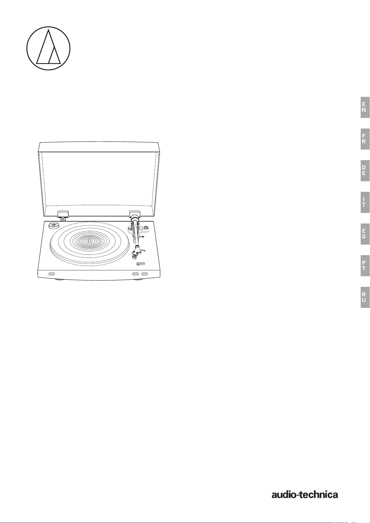
AT-LP3
User Manual
Fully Automatic Belt-Drive Turntable
Manuel de l’utilisateur
Tourne-disque à entraînement par courroie
entièrement automatique
Manuel de l’utilisateur
Vollautomatischer, riemenbetriebener
Plattenspieler
Manuale dell’utente
Giradischi con trasmissione a cinghia
totalmente AUTOMATICO
Manual de usuario
Tocadiscos de transmisión por correa
totalmente automático
Manual do Usuário
Toca-discos acionado por correia
totalmente automático
EN
FR
DE
IT
ES
PT
Руководство пользователя
Полностью автоматический проигрыватель
виниловых пластинок с ре менным приводом
RU
Page 2
Introduction
Thank you for purchasing this Audio-Technica product.
Read through this user manual before using the product to ensure its correct use. Also, keep this manual, along with the warranty, for future reference.
This product is only for use in the following countries. Make sure that the operating voltage of the product is correct for the country you live in.
Country list: EU, Russia
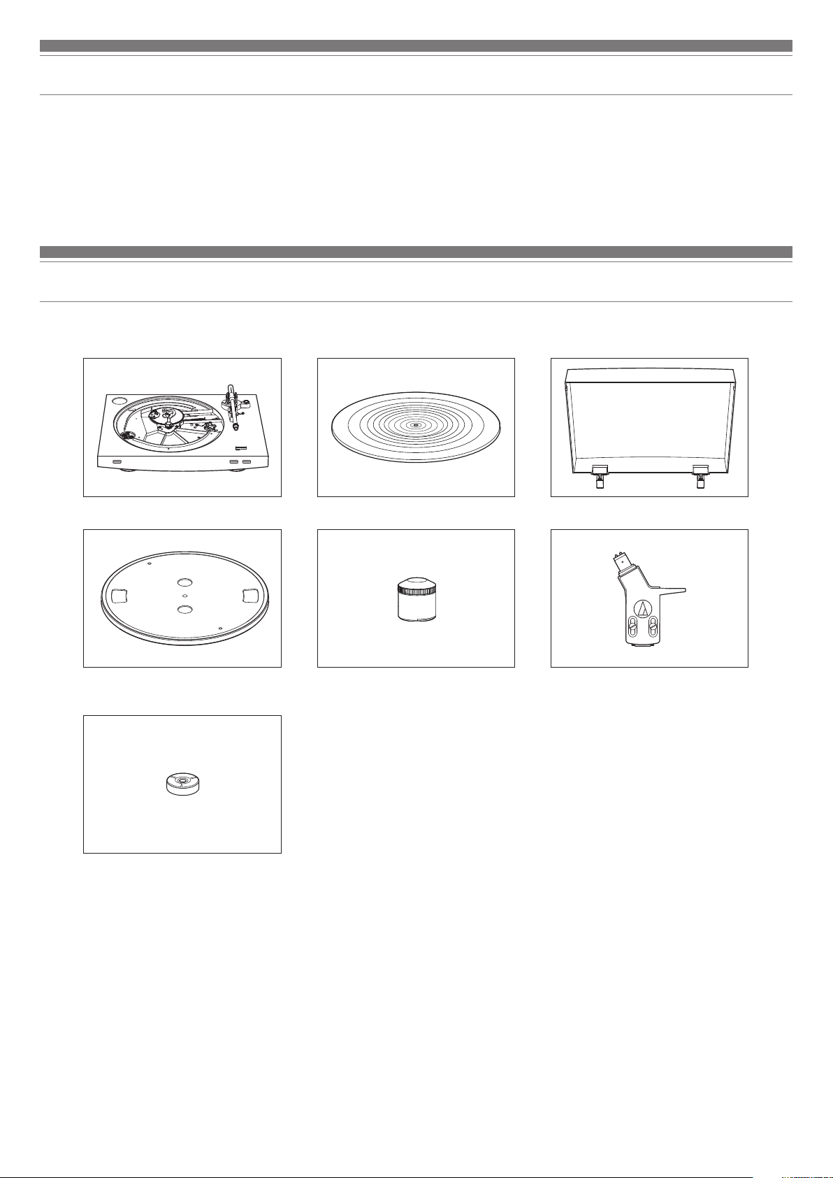
Package contents
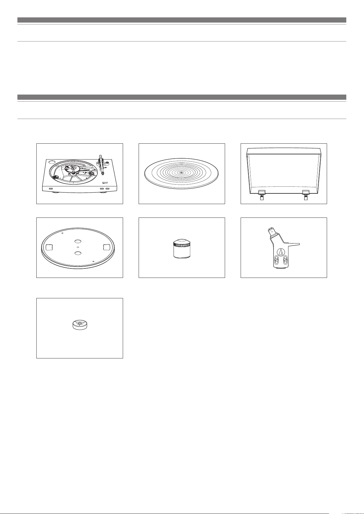
Make sure that you have all the included items listed below before using this product.
If some items are missing or damaged, contact your local Audio-Technica dealer.
•
Turntable body
•
Platter (with drive belt)
•
45 RPM adapter
•
Power cable (Use the correct power cable for the country you live in.)
•
User manual (this document)
•
Rubber mat
•
Counterweight
•
After purchase, we suggest that you save all packaging materials for possible future storage, moving, or shipping.
•
Dust cover
Headshell (AT-HS3) with VM stereo cartridge
(AT91R)
1
Page 3

Safety precautions
Important information
Warning:
To prevent fire or shock hazard, do not expose this apparatus to rain or moisture.
Caution:
Do not expose this apparatus to drips or splashes.
To avoid electric shock, do not open the cabinet.
Refer servicing to qualified personnel only.
Do not expose this apparatus to excessive heat such as sunshine, fire or the like.
Do not subject this apparatus to strong impact.
This apparatus should be located close enough to the AC outlet so that you can easily grasp the power cord plug at any time.
In case of emergency, disconnect the power cord plug of this apparatus quickly.
Do not place any objects filled with liquids, such as vases, on this apparatus.
To prevent fire, do not place any naked flame sources (such as lighted candles) on this apparatus.
Do not install this apparatus in a confined space such as a bookcase or similar unit.
To install this apparatus only in the place where ventilation is good.
Notes on use
EN
Turntable body
•
Do not set and use the product in locations that are considerably hot or humid, dirty, or subject to extreme vibrations.
•
The product should be positioned on a flat, level surface.
Cartridge
•
Attach the provided protector to the cartridge when the product is not in use.
•
Do not touch the stylus of the cartridge with your finger.
•
Do not allow the stylus to bump against the platter, rubber mat, or edge of the record.
2
Page 4
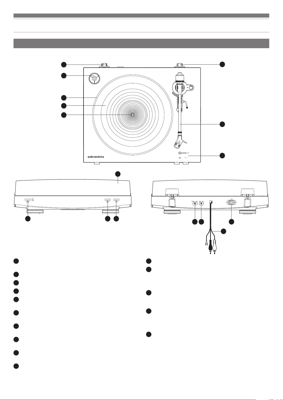
Part names and functions
Overall diagram
5
1
2
3
4
11
5
6
7
8 9
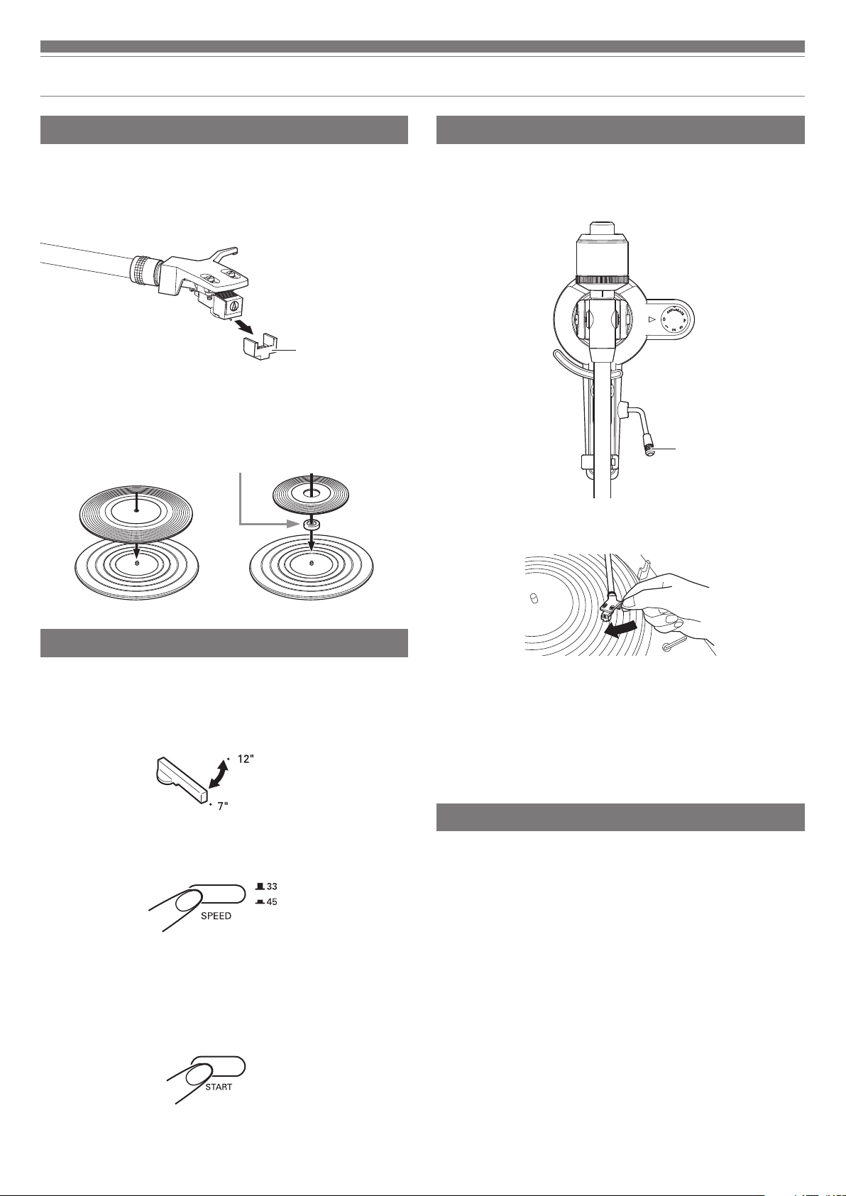
45 RPM adapter (shown in receptacle)
1
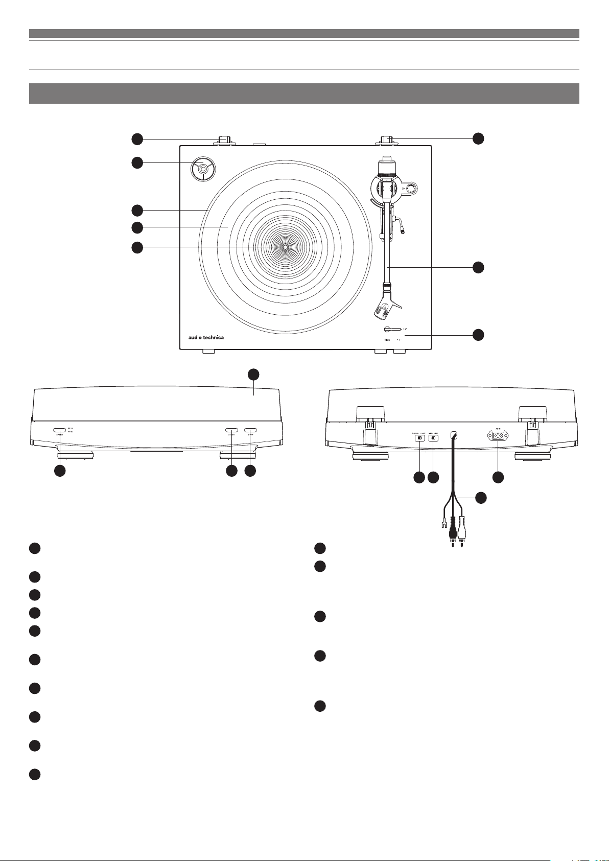
Select the platter speed (33-1/3 or 45 RPM).
Platter
2
Rubber mat
3
Spindle
4
Dust cover hinge holders
5
Attachment points for dust cover hinges.
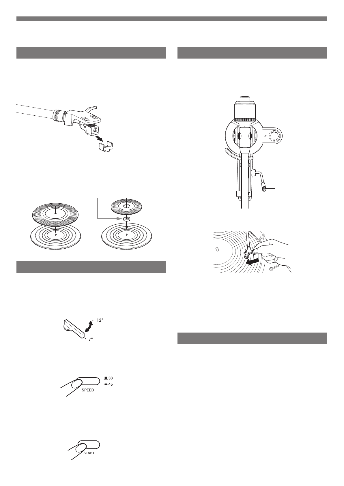
Tonearm part
6
For details, refer to “Tonearm” on p. 4.
Size selector
7
Switch between 12" and 7", according to the size of the record.
Platter speed button
8
Select the platter speed (33-1/3 or 45 RPM).
START button
9
Spins the platter and moves the tonearm.
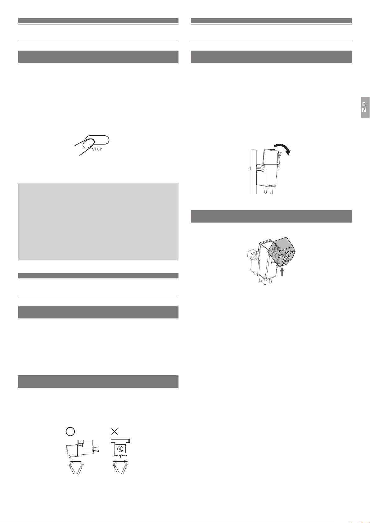
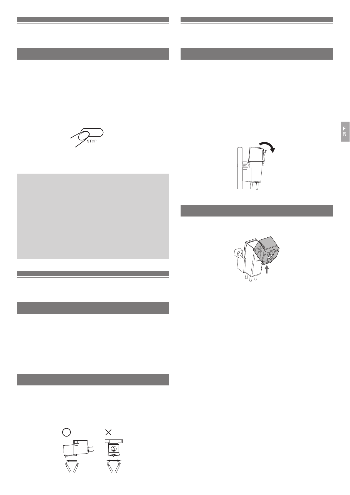
STOP button
10
Returns the tonearm to its original position and stops the platter.
10
12 13
Dust cover
11
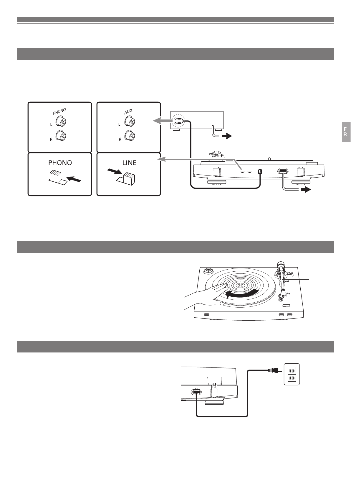
Pre-amplifier selector switch
12
If using an amplifier with a PHONO input jack, set this switch to the
PHONO position. If connecting to the AUX jack of an amplifier, set this
switch to the LINE position.
MM (VM)/MC cartridge selector switch
13
If using an MM (VM) cartridge, set this switch to the MM position. If
using an MC cartridge, set this switch to the MC position.
RCA audio cable (with grounding wire)
14
Connect to PHONO input jack (grounding wire to ground terminal, if
available) or AUX (LINE) input jack of a receiver, amplifier or other
connectable equipment.
AC inlet
15
Insert the power cable here.
15
14
3
Page 5
Part names and functions
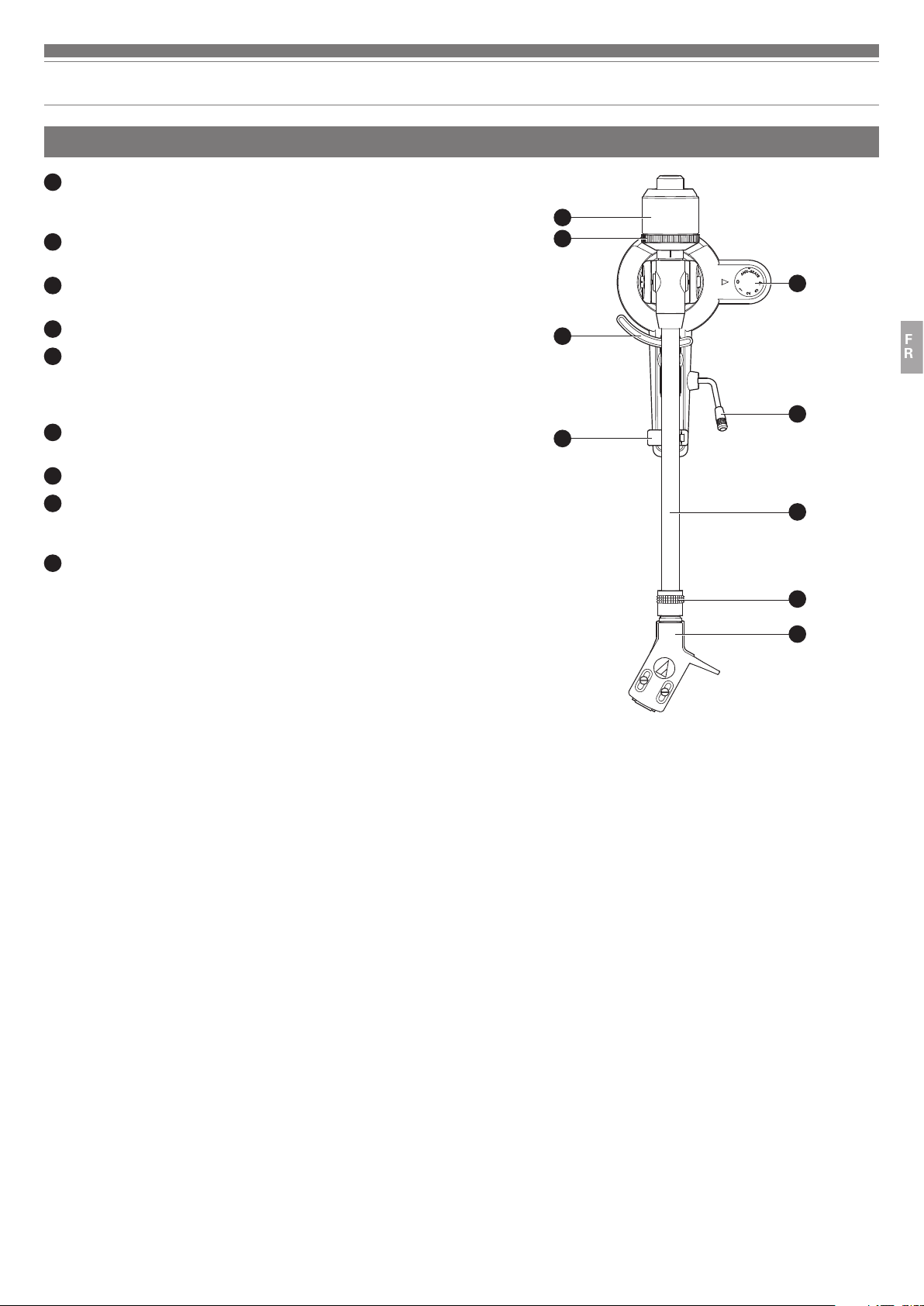
Tonearm
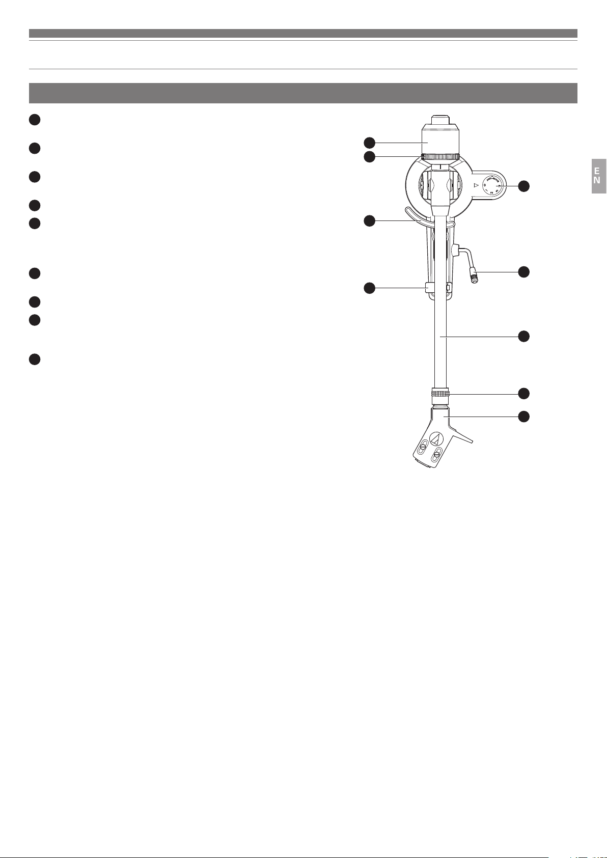
Counterweight
1
Balances the tonearm and adjusts to provide the proper tracking force.
Tracking force gauge ring
2
Use to adjust the tracking force.
Tonearm lift
3
Moves the tonearm vertically to and from the face of the record.
Tonearm rest
4
Anti-skate control dial
5
While the record is playing, a force acts on the stylus tip to pull it inward.
This force can be counteracted by setting the same values for anti-skate
and the tracking force.
Tonearm lift control lever
6
Operates the tonearm lift.
Tonearm
7
Locking ring
8
Rotate the ring to the left (counterclockwise) to secure the headshell. To
remove the headshell, rotate the ring to the right.
Headshell and cartridge
9
The cartridge (AT91R) is mounted to the headshell (AT-HS3).
1
2
5
3
6
4
7
EN
8
9
4
Page 6
Preparation for use
Installing the turntable
•
Mount the product on a level surface.
•
To avoid the effects of vibrations and acoustic pressure, do not mount the
product next to such items as speakers.
•
The product may pick up radio static if placed next to a radio. Therefore, try
to keep the product away from radios.
•
If the product is near equipment (cell phone, etc.) that emits strong radio
waves, noise may occur.
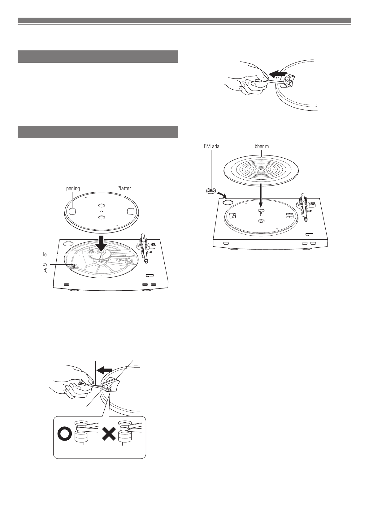
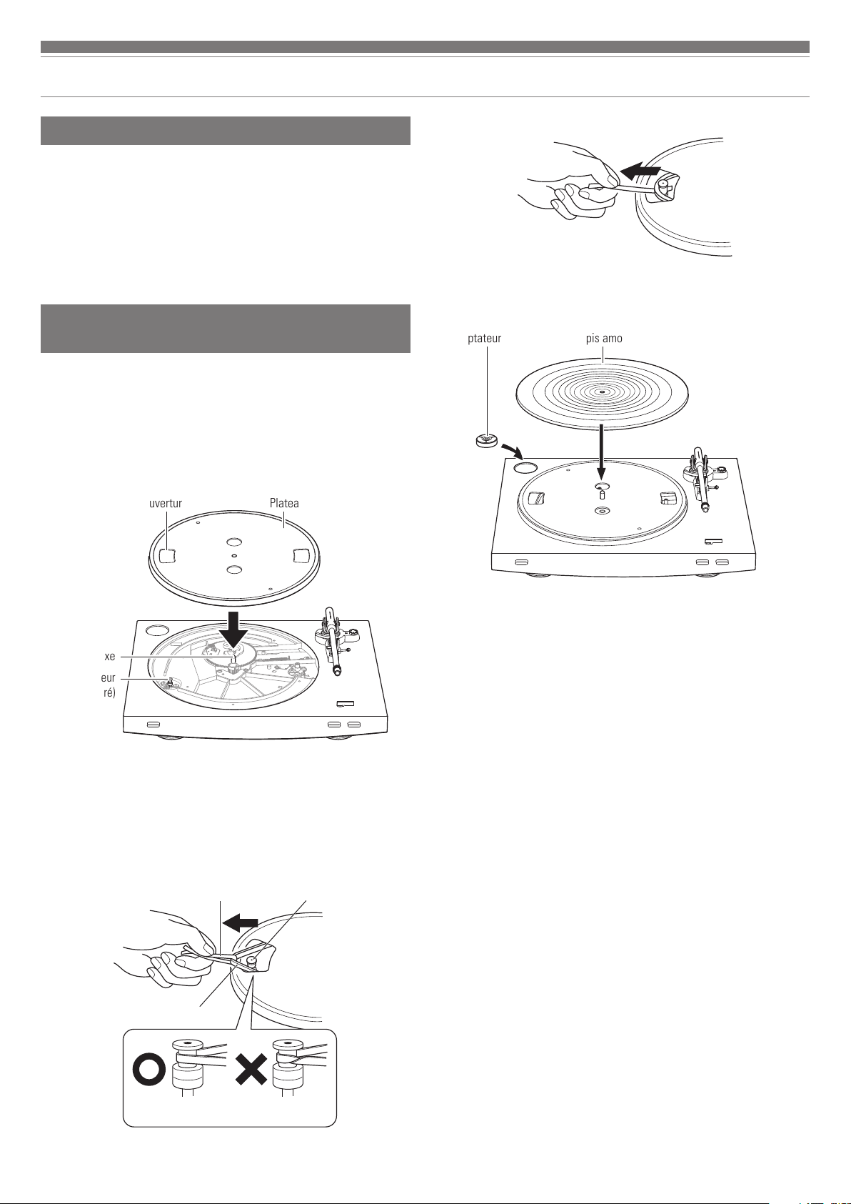
Placing the platter and the rubber mat
This product requires some assembly before using it for the first time.
Do not connect the power cable until assembly is complete.
1. Set the platter on the spindle.
•
Make certain that the platter is fully seated on the spindle.
PlatterOpening
3. Remove the red ribbon from the belt.
4. Set the rubber mat on the platter.
•
After setting the rubber mat, put the 45 RPM adapter into the space made for it
on the upper left.
Rubber mat45 RPM adapter
Spindle
Motor pulley
(brass-colored)
2. Place the belt on the motor pulley (brass-colored).
•
Align one of the platter openings with the brass motor pulley, and, while pulling
both ends of the red ribbon that comes attached to the belt, place the belt on the
motor pulley, as per the diagram. When doing this, be careful not to twist the
belt.
Motor pulley
Red ribbon
Belt
(brass-colored)
Straight Twisted
5
Page 7
Preparation for use
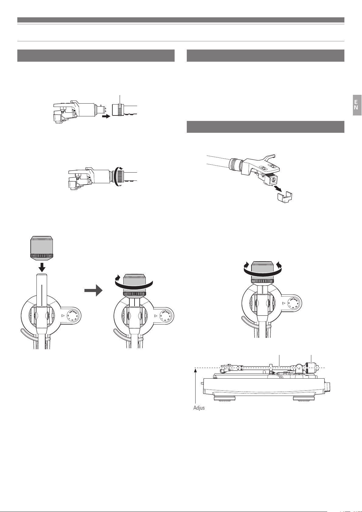
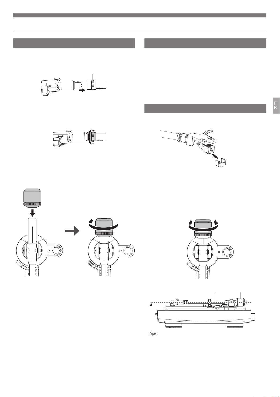
Assembling the tonearm
1. Insert the headshell into the locking ring.
•
Hold the right and left edges of the headshell so that you do not damage the
stylus or cut the cartridge’s wires.
Locking ring
2. With the headshell inserted, turn the locking ring
counterclockwise (to the left).
3. With the tracking force gauge ring facing forward, attach
the counterweight to the back of the tonearm, and slowly
turn it counterclockwise (to the left).
Tonearm balance and tracking force
In order for the cartridge to pick up sound correctly from the record’s grooves,
the tonearm’s balance and tracking force must be adjusted to fit the
specifications of the cartridge. If the tonearm’s balance and tracking force are
not properly adjusted, the record or the cartridge’s stylus may become damaged.
•
Do not drag the cartridge’s stylus across the record or rubber mat when
adjusting the tonearm’s balance or tracking force. Doing so may damage the
stylus.
Setting tonearm balance
1. Remove the cartridge’s protector.
2. While holding headshell, remove the cable tie used to
secure the tonearm at the time of delivery.
3. While still lightly holding the headshell, turn the
counterweight to adjust the tonearm’s balance.
•
Adjust the balance so that the tonearm is level when you release the headshell.
EN
Tonearm Counterweight
Adjust so that tonearm is level
4. Return the tonearm to the tonearm rest.
6
Page 8
Preparation for use
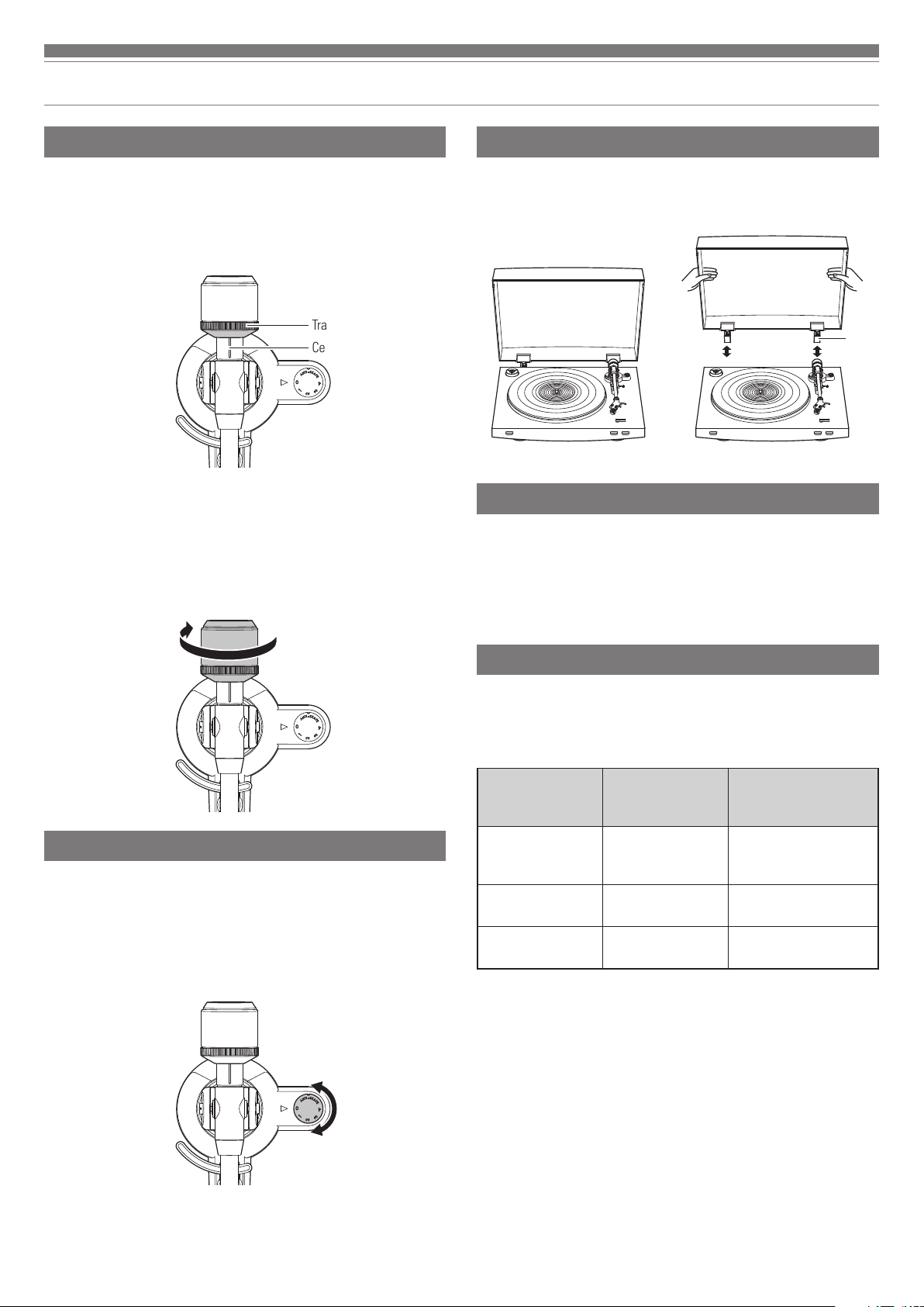
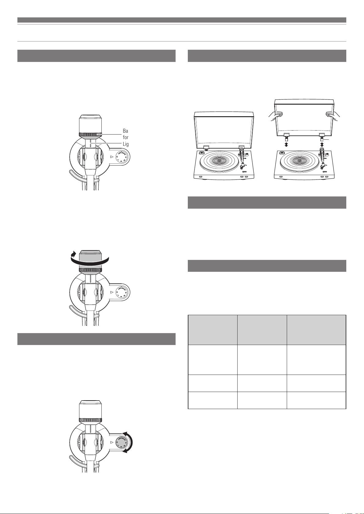
Setting tracking force
1. While supporting the counterweight so that it does not
move, turn the tracking force gauge ring so that its “0”
position lines up with the centerline on the back of the
tonearm (the tracking force is not adjusted simply by
turning the tracking force gauge ring).
Tracking force gauge ring
Centerline
2. Turn the counterweight and the tracking force gauge
ring together counterclockwise until the centerline value
matches the recommended tracking force value for the
cartridge you are using.
•
Refer to the cartridge maker’s specifications for the recommended tracking force
value.
•
The tracking force value for the cartridge provided with this product is 2.0 g.
Installing/removing the dust cover
When attaching the dust cover, insert the hinges of the dust cover into the
two dust cover hinge holders on the back of the body. When removing the dust
cover, slowly pull the dust cover out from the dust cover hinge holders.
Hinge
Setting MM (VM)/MC Cartridge Selector Switch
If using a moving magnet (MM or VM) cartridge, set this switch to the MM
position. If using a moving coil (MC) cartridge, set this switch to the MC
position.
•
This switch is set to the MM position at the time of purchase. This is the
correct setting for the AT91R VM stereo cartridge included with the product.
Setting the anti-skate adjustment
While the record is playing, a force acts on the stylus tip to pull it inward. This
force can be counteracted by setting the same values for anti-skate and the
tracking force.
1. Adjust the anti-skate control dial to have the same value
as the tracking force value.
•
The tracking force value for the cartridge provided with this product is 2.0 g.
Setting pre-amplifier selector switch
This product has a built-in phono equalizer function. You can use the product,
even if you do not have a phono amplifier or connectable equipment with a
built-in phono amplifier.
Use the pre-amplifier selector switch to set the output, as shown below.
Connectable
equipment being
used
Device with phono
input
Device without phono
input
PC sound card LINE PC sound card’s line input
*1
An audio adapter (sold separately) may be required to connect the RCA audio cable to
the line input jack of the PC sound card.
Position of
pre-amplifier
Where to connect
RCA audio cable
selector switch
PHONO Phono input jack and
ground (earth) terminal of
connectable equipment
LINE AUX or line input jack of
connectable equipment
*1
jack
7
Page 9
Preparation for use
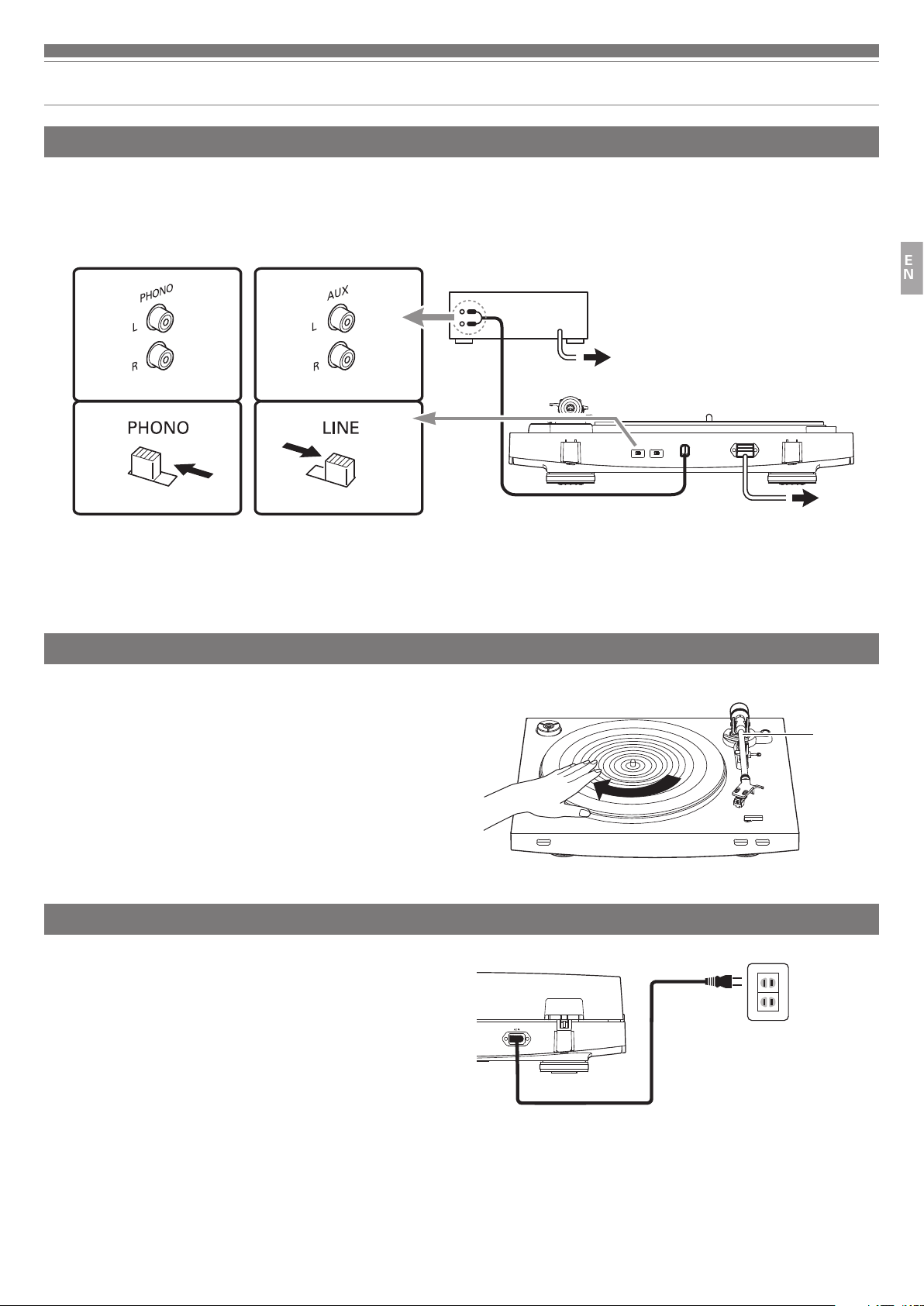
Connecting the device
Align the settings for the pre-amplifier selector switch and connect the RCA audio cable to an input jack that is compatible with the connectable equipment you are
using (amplifier, receiver, active speakers, sound card, etc.).
•
The RCA audio cable's red jack is for the right (R) channel, and the white jack is for the left (L) channel.
With PHONO
*1
Depending on the connectable equipment you are using, a ground
*1
Without PHONO
(earth) terminal may be present near the phono input jack. If this is
the case, connect the grounding wire of the RCA audio cable to it.
This will help prevent a low humming noise that might otherwise
be heard during playback.
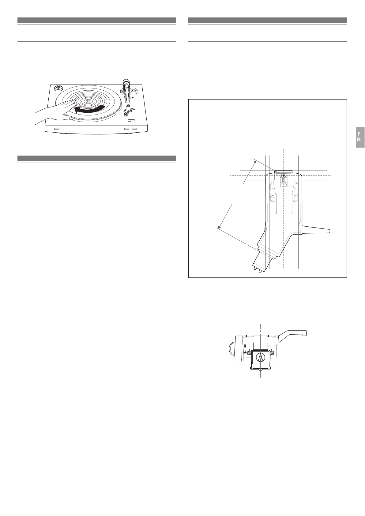
Rotating the platter
1. Using your hands, rotate the platter ten times.
•
Raise the tonearm lift control lever to lift the tonearm. Slowly rotate the turntable
ten times by hand in the direction of the arrow.
•
You may want to hold the tonearm to prevent it from moving. This step is for
resetting the auto mechanism, getting rid of any twists in the belt and making
sure the belt rides smoothly along the drive rim on the underside of the platter.
Connectable equipment
(Amplifier, etc.)
EN
To outlet
To outlet
Tonearm
Connecting the power cable
This product does not have a power switch. A standby current is always running
through the product, even when it is not being used; disconnect the power cable
plug from the outlet when not using the product for a long period of time.
1. Connect the power cable plug to the outlet.
•
For safety, raise the tonearm by lifting the tonearm lift control lever to the UP
position.
•
Connect the power cable plug to the outlet without removing the cartridge’s
protector. If the platter has rotated, press the STOP button without touching the
tonearm, and then wait until the tonearm returns to its original position.
•
If you play a record immediately after inserting the power cable, the sound that
is played may be garbled. Wait a short time (about 30 seconds) after plugging the
power cable plug into the outlet before playing a record.
8
Page 10
Playing a record
Before playing a record
1. Remove the cartridge’s protector.
•
Pull the protector straight forward to remove it.
•
Applying a downward force may cause the stylus to come off the body. Only low
volume is output if the stylus has come off, or is about to come off, so refer to
“Replacing the stylus” on p. 10 to reattach the stylus correctly.
protector
2. Place the record on the rubber mat so that the center
hole aligns with the spindle.
•
If playing a 45 RPM record with a large center hole, attach the 45 RPM adapter
(see the right side of the diagram below).
45 RPM adapter
Manual operation
Lower the volume of the amplifier, speakers, etc. sufficiently.
1. Raise the tonearm by lifting the tonearm lift control lever
to the UP position.
Tonearm lift control lever
2. Position the tonearm over the desired location (groove)
on the record.
Automatic operation
Lower the volume of the amplifier, speakers, etc. sufficiently.
1. Select the size with the size selector.
•
Select “12"” for an LP record with a 12" diameter, and “7"” for a 45 RPM record
with a 7" diameter.
2. Press the speed with the platter speed button.
•
Select “33” for a 33-1/3 RPM record, and “45” for a 45 RPM record.
3. Press the START button.
•
Do not bump the product while the record is playing.
•
Do not switch the record size selection while the record is playing. Doing either of
these can cause the product to malfunction.
3. Lower the tonearm by moving the tonearm lift control
lever to the DOWN position. The tonearm descends
slowly onto the record and play begins.
•
Alternatively, you can skip steps 1 to 3, and use the finger-lift on the headshell to
position the tonearm over the desired location on the record. Carefully lower the
tonearm to the record surface.
•
Do not subject the product to strong impact during playback.
Pausing the record
1. After lowering the volume of the amplifier, speakers, etc.
sufficiently, lift the tonearm with the tonearm lift control
lever.
9
Page 11
Playing a record
Replacing the stylus
Stopping the record
Once the record has been played until the end, the tonearm automatically
returns to the tonearm rest.
To manually stop the record, do the following.
1. Lower the volume of the amplifier, speakers, etc.
sufficiently.
2. Press the STOP button.
•
Once the record stops playing, the tonearm automatically returns to the tonearm
rest.
3. Remove the record after the platter has come to a
complete stop.
•
When the tonearm reaches the end (center) of the record, it will automatically
lift and return to the tonearm rest. Do not interfere with its motion. Doing so can
cause the product to malfunction. If the tonearm does not lift and return to the
tonearm rest, press the STOP button to complete this operation.
•
If the rubber mat gets dirty, it can easily scratch the record, so remove the
rubber mat periodically and wipe off any dust.
•
To prevent the record from scratches and warping, remove it after use.
•
Do not use a disk stabilizer.
•
Do not use a platter other than the one provided.
•
This product is not intended for DJs. Do not touch the record or the platter while
the record is playing.
Removing the stylus
•
In addition to the deterioration of sound quality, records may also be
damaged as the cartridge’s stylus tip wears down.
•
As a rule of thumb, replace the stylus after 300 to 500 hours of use.
•
Be sure to disconnect the product’s power cable plug from the outlet.
1. Release the headshell from the tonearm.
•
Hold the tonearm tightly and then remove the headshell gently.
2. Remove the protector from the cartridge.
3. Remove the stylus by pulling in the direction of the arrow.
Installing a new replacement stylus
1. Mount the new replacement stylus to the cartridge.
EN
Care
Turntable body
•
When the turntable body is dirty or dusty, first disconnect the power cable
plug, and then wipe off the dirt and dust with a soft, dry cloth.
•
Do not use benzenes, thinners, etc.
•
When storing the product for a long time, disconnect the power cable plug
from the outlet and wrap the equipment in plastic; do not allow it to become
damp.
Stylus tip
•
If dirt and grime are stuck to the stylus tip, clean it with a commercially sold
brush.
•
We recommend using a stylus cleaner (sold separately) if the stylus tip is
considerably dirty. Clean the stylus tip by moving the brush from the rear to
the front of the stylus tip.
Engage rear tab first.
2. Mount the protector onto the cartridge.
3. Mount the headshell onto the tonearm.
10
Page 12
Replacing a cartridge
Replacing a new cartridge
Refer to the user manual for the cartridge that you will be using if you are
replacing the cartridge (AT91R) included with this product with another,
commercially sold cartridge. After you replace the old cartridge with a new one,
you must readjust the overhang and the tonearm’s balance and tracking force.
1. Release the headshell from the tonearm.
•
Hold the tonearm tightly and then remove the headshell gently.
2. Remove the stylus from the cartridge.
•
Refer to “Removing the stylus” on p. 10.
3. Remove the lead wires.
•
Be careful not to damage the lead wires.
4. Using a commercially sold, non-metallic slotted
screwdriver, remove the installation screws, and then
remove the cartridge from the headshell.
Replacing the belt
•
The belt is a consumable part. Replace the belt if the speed of playback
slows down or irregular rotation occurs. As a rule of thumb, we suggest
replacing the belt once a year.
•
Before replacing the belt, be sure to disconnect the product’s power cable
plug from the outlet.
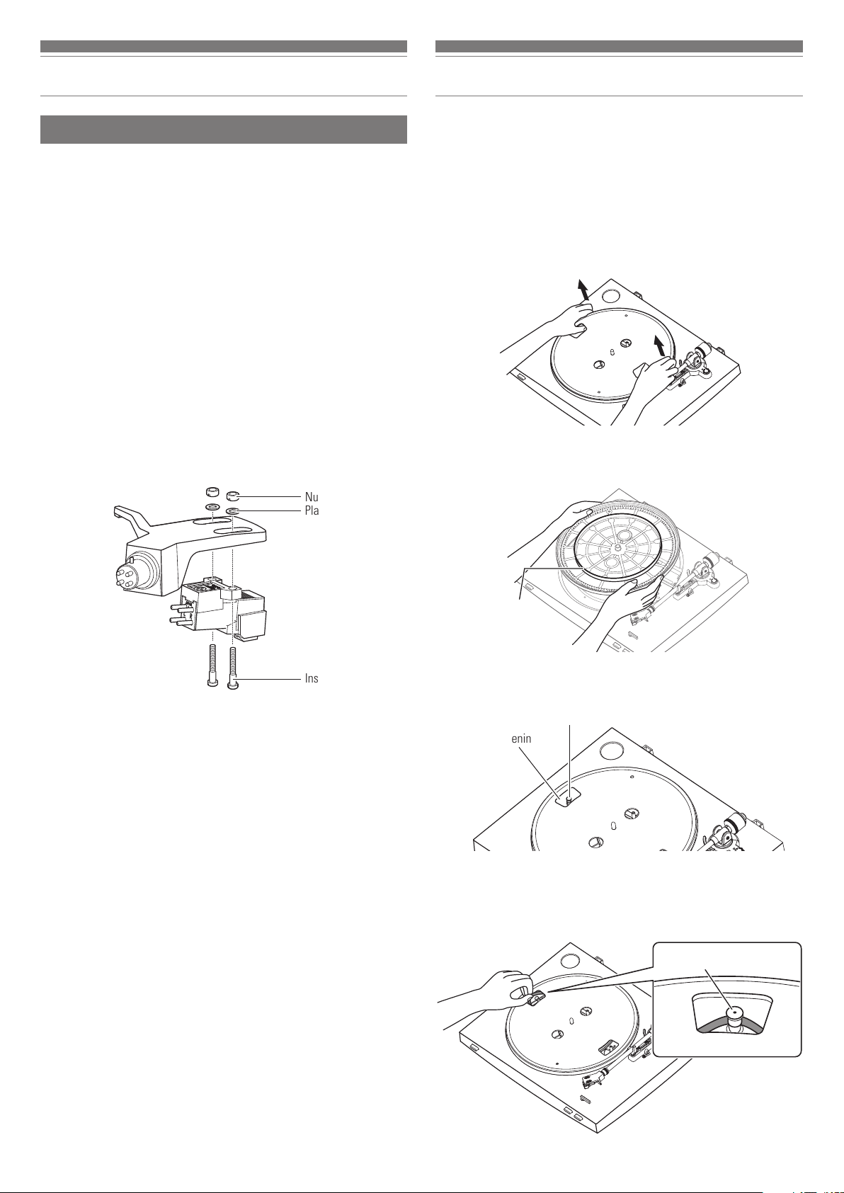
1. Remove the rubber mat.
2. Remove the platter, turn the platter over, and then
remove the old belt.
•
Place your thumbs in the openings and pull up strongly.
5. Refer to the user manual for the new cartridge for
mounting instructions.
Nuts
Plastic washers
Installation screws
6. Using a commercially sold, non-metallic slotted
screwdriver, tighten the screws in both places, and then
adjust the overhang.
•
Refer to "Adjusting the overhang" on p. 12.
•
After the adjustments are complete, tighten the screws securely.
7. Attach the headshell to the tone arm.
3. Place the new belt around the inner circle.
•
Be careful not to twist the belt while doing this.
Belt
4. Attach the platter.
•
Align one of the openings with the position of the motor pulley (brass-colored).
Motor pulley (brass-colored)
Opening
8. Adjust the tonearm balance and tracking force.
•
Refer to “Tonearm balance and tracking force” on p. 6 to perform the
readjustments.
11
5. Place the belt on the motor pulley (brass-colored).
•
Grasp the belt that was attached in step 3 and, while pulling it, place it on the
brass motor pulley.
Motor pulley (brass-colored)
Place the belt
Page 13
Replacing the belt
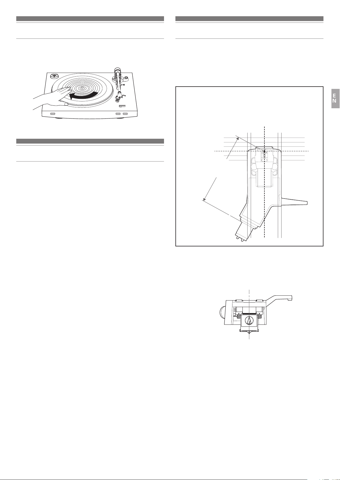
Adjusting the overhang
6. Using your hands, rotate the platter ten times.
•
Raise the tonearm lift control lever to lift the tonearm. Slowly rotate the turntable
ten times by hand in the direction of the arrow.
When the turntable is moved
Using the product's original packing materials, wrap the turntable in the
reverse order from when you unwrapped it. If you do not have the packaging
materials, take the following measures:
•
After disconnecting the power cable plug from the outlet, remove the rubber
mat and platter, and then wrap them so that they do not get damaged.
•
Use a string or something similar to tie the tonearm to the rest so that it
does not move.
•
Remove the counterweight.
•
Remove the headshell from the tonearm with the protector attached to the
cartridge, and then wrap the entire headshell assembly so that it does not
get damaged.
•
Wrap the turntable body with paper or a soft cloth so that it does not get
damaged.
The position of the cartridge must be accurately determined (adjusting the
overhang) when mounting a cartridge or headshell other than the one provided.
1. Mount the cartridge so it is parallel to the headshell.
•
Match up the positions of the cartridge and headshell to the figure below and
mount the cartridge so it is parallel to the headshell.
Overhang adjustment guide
This illustration represents the actual size.
Place the headshell on the figure below, and then adjust the stylus tip of
the new cartridge along the lines for the "Stylus tip" of the cartridge.
Underside of headshell
Stylus tip
45.0 mm
EN
2. Mount the cartridge it is perpendicular to the top of the
headshell.
Front of headshell
12
Page 14
Troubleshooting
Problem Solution
•
The platter does not spin.
The platter spins, but there is no
sound or the volume is not loud
enough.
The stylus skips.
There is howling.
There is noise when the record is
playing.
The sound when the record is playing
is either too fast or too slow.
Playback speed slows down or there
is irregular rotation.
Hum is heard during playback.
Is the power cable plug connected to the outlet? Connect the power cable plug to the outlet.
•
Has the belt slipped from the platter? Correctly place the belt on the platter.
•
Is the belt placed on the motor pulley? Check that the belt is placed on the motor pulley (brass-colored) correctly.
•
Has the belt been damaged? Replace it with a new belt.
•
Are the function settings and input for connected equipment (amplifier, etc.) selected correctly? Check whether the
settings for the connected equipment are correct.
•
Is the stylus damaged? Check the stylus and replace it, if necessary.
•
Is the stylus placed correctly on the body of the cartridge? Check the cartridge and adjust it, if necessary.
•
Are the setting positions for the pre-amplifier selector switch correct? Check that the pre-amplifier settings are
correct, noting the following common problems and their causes:
– If there is no sound, or if the volume is not loud enough, the product is set to the “PHONO” position and connected
to the amplifier’s AUX/LINE input.
– If the volume is too loud or is distorted, the product is set to the “LINE” position, and the connectable equipment is
connected to the PHONO input.
•
Is the tracking force set too heavy? Adjust the tracking force.
•
Is the tracking force set too light? Adjust the tracking force.
•
Is the anti-skate set improperly? Verify anti-skate is set for same value as cartridge tracking force.
•
Is the record warped? Check the record.
•
Is the record scratched? Check the record.
•
Is the product picking up excessive vibrations from the floor, surfaces of the walls, or nearby speakers? Decrease the
vibrations or mount the product on a surface that is not subject to the effects of vibrations.
•
Is the product mounted on an unstable surface? Check whether the surface on which the product is mounted is suitable.
•
Is there dust on the cartridge’s stylus tip? If dust is stuck to the stylus tip, clean it with a commercially sold brush.
•
Are the speed settings for this product correct? Use the platter speed button to select the correct speed for the type
of record being played.
•
Is the belt stretched out? Replace it with a new belt.
•
Is the ground line connected correctly? Make sure the ground line is properly connected.
•
Is the headshell attached to the tonearm firmly? Make sure the locking ring is tight.
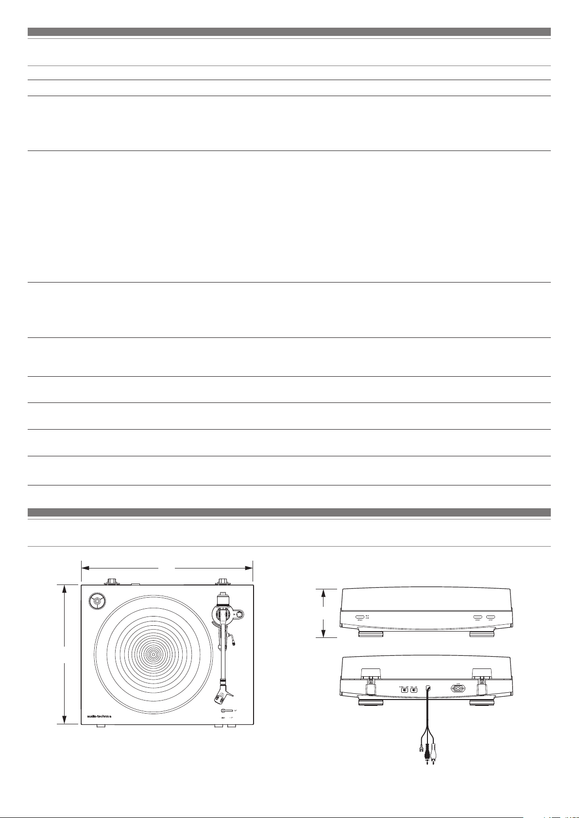
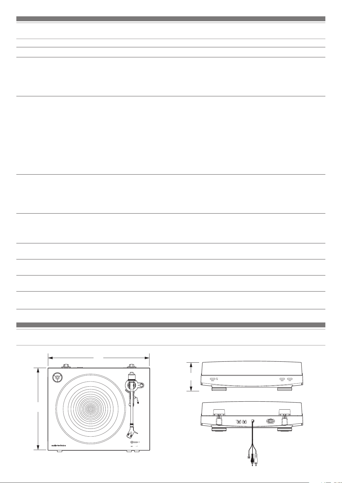
Dimensions
353
13
435
(Unit: mm)
128
Page 15
Specifications
Turntable specifications
Type 2-Speed, fully automatic operation
Motor DC motor
Drive method Belt drive
Speeds 33-1/3 RPM, 45 RPM
Turntable platter Die-cast aluminium
Wow and flutter < 0.2 % WRMS (33 RPM) at 3 kHz
Signal-to-noise ratio > 60 dB
Outputs levels
“PHONO”
“LINE (MM)”
Phono Pre-amp gain (MM)
Phono Pre-amp gain (MC)
Tonearm specifications
Type Static balanced straight shaped w/soft
Effective length 221.5 mm
Overhang 19 mm
Maximum tracking error angle Less than 3°
Stylus pressure adjustment range 1 to 4 g
Applicable cartridge weight range
(including headshell)
3.5 mV nominal at 1 kHz, 5 cm/sec
220 mV nominal at 1 kHz, 5 cm/sec
36 dB nominal, RIAA equalized
56 dB nominal, RIAA equalized
damping control
14.5 to 20 g
General specifications
Power supply requirements 220 to 240 V / 50, 60 Hz
Power consumption 2 W
Dimensions 435 mm (17.13")×353 mm (13.90")×
128 mm (5.04")
(W×D×H)
Weight 5.2 kg (11.46 lbs)
Accessories included Rubber mat, Dust cover, Platter (with
drive belt), Counterweight, Headshell
(AT-HS3) with VM stereo cartridge
(AT91R), 45 RPM adapter, Power cable*
Replacement stylus (sold
separately)
Replacement headshell (sold
separately)
Replacement belt (sold separately) AT-LP3 exclusive belt
*Use the correct power cable for the country you live in.
Specifications are subject to change without notice due to improvements.
ATN91R
AT-HS3
EN
Cartridge and headshell specifications
Cartridge Model AT91R
Cartridge Type VM Dual Magnet
Recommended load impedance 47,000 ohms
Output voltage 3.5 mV (mV at 1 kHz, 5 cm/sec)
Stylus 0.6 mil bonded conical
Cantilever Aluminum pipe
Tracking force range 1.5 to 2.5 g (standard 2.0 g)
Cartridge weight 5.0 g
Headshell model AT-HS3
Headshell weight 11.1 g
Headshell overhang adjustment 8 mm
14
Page 16
Introduction
Nous vous remercions d’avoir fait l’acquisition de ce produit Audio-Technica.
Avant utilisation, merci de lire attentivement ce manuel pour vous assurer du bon usage du produit. De meme, veuillez conserver ce manuel ainsi que la garantie
pour consultations ultérieures.
Ce produit n’est destiné qu’à une utilisation dans les pays suivants. Veillez à ce que la tension d’utilisation du produit corresponde à celle utilisée dans le pays où
vous vivez.
Liste des pays : Union européenne, Russie
Contenu de l’emballage
Assurez-vous que tous les articles inclus répertoriés sur la liste ci-dessous soient présents avant d’utiliser le produit.
Si certains éléments sont manquants ou endommagés, contactez votre distributeur local Audio-Technica.
•
Corps du plateau de la platine
•
Plateau (avec courroie d’entraînement)
•
Tapis amortissant en caoutchouc
•
Contrepoids
•
Câble d’alimentation (Utilisez le câble d’alimentation adéquat pour le pays dans lequel où vous
•
•
Couvercle anti-poussière
Porte-cellule (AT-HS3) avec cellule stéréo VM
vivez.)
•
Manuel d’utilisation (ce document)
•
Adaptateur 45 tours
Après l’achat, nous vous suggérons de conserver tous les emballages pour un éventuel stockage, déménagement, ou transport.
(AT91R)
1
Page 17

Consignes de sécurité
Informations importantes
Avertissement:
Pour éviter tout risque de choc électrique ou d’incendie, n’exposez pas cet appareil à la pluie ou à l’humidité.
Mise en garde:
Protégez cet appareil des projections et des gouttes d’eau.
Pour éviter tout risque de choc électrique, n’ouvrez pas le boîtier.
Confiez tous travaux d’entretien à un technicien qualifié.
N’exposez pas cet équipement à des températures excessives, telles que celles de la lumière directe du soleil, d’une flamme ou autres.
Ne soumettez pas cet équipement à de forts impacts.
Placez l’appareil à proximité d’une prise de courant pour une utilisation aisée du câble d’alimentation.
En cas d’urgence, déconnectez immédiatement la prise du câble d’alimentation de l’appareil.
Ne placez pas d’objets remplis de liquides, tels que des vases, sur l’appareil.
Pour éviter tout risque d’incendie, ne placez pas de flammes nues (telles que des bougies allumées) sur l’appareil.
N’installez pas cet appareil dans un espace confiné tel qu’une étagère ou un endroit similaire.
Installez cet appareil uniquement dans des endroits avec une bonne ventilation.
Remarques d’utilisation
FR
Corps du plateau de la platine
•
Ne placez pas et n’utilisez pas le produit dans des endroits soumis à de fortes chaleurs ou une humidité élevée, très sales ou soumis à des vibrations extrêmes.
•
Le produit doit être placé sur une surface plane et lisse.
Cellule
•
Fixez la protection fournie sur la cellule lorsque le produit n’est pas utilisé.
•
Ne touchez pas la pointe de lecture de la cellule avec votre doigt.
•
Empêchez la pointe de lecture de percuter le plateau, le tapis amortissant en caoutchouc ou le bord du disque.
2
Page 18
Noms des pièces et fonctions
Schéma de l’ensemble
5
1
2
3
4
11
5
6
7
8 9
Adaptateur 45 tours (affiché dans le réceptacle)
1
Sélectionnez la vitesse du plateau (33-1/3 ou 45 tours).
Plateau
2
Tapis amortissant en caoutchouc
3
Axe
4
Supports de charnières du couvercle anti-poussière
5
Points de fixation pour les charnières du couvercle anti-poussière.
Bras de lecture
6
Pour plus de détails, reportez-vous à la section “Bras de lecture” en p. 4.
Sélecteur de taille
7
Permuter entre 12" et 7", en fonction de la taille du disque.
Bouton de vitesse du plateau
8
Sélectionnez la vitesse du plateau (33-1/3 ou 45 tours).
Bouton START
9
Fait tourner le plateau et déplace le bras de lecture.
Bouton STOP
10
Replace le bras de lecture dans sa position d’origine et arrête le plateau.
10
12 13
Couvercle anti-poussière
11
Sélecteur de préamplificateur
12
Si vous utilisez un amplificateur avec une prise entrée PHONO, placez le
sélecteur en position PHONO. En cas de connexion d’un amplificateur à la
prise AUX, placez ce sélecteur sur la position LINE.
Sélecteur de cellule MM (VM)/MC
13
Si vous utilisez une cellule MM (VM), placez ce sélecteur en position
MM. Si vous utilisez une cellule MC, placez ce sélecteur en position MC.
Câble audio RCA (avec câble de mise à la terre)
14
Raccordez la prise d’entrée PHONO (câble de mise à la terre à la borne
de mise à la terre, si disponible) ou la prise d’entrée AUX (LINE) d’un
récepteur, amplificateur ou autre équipement connecté.
Entrée d’alimentation
15
Insérez le câble d’alimentation ici.
15
14
3
Page 19
Noms des pièces et fonctions
Bras de lecture
Contrepoids
1
Equilibre le bras de lecture et permet un réglage pour obtenir la force
d’appui adéquate.
Bague de réglage de la force d’appui
2
Utilisez pour régler la force d’appui.
Porte-bras de lecture
3
Déplace le bras de lecture verticalement vers et depuis la face du disque.
Pose-bras de lecture
4
Cadran de contrôle anti-skating
5
Pendant la lecture du disque, une force agit sur la pointe de lecture pour
la tirer vers l’intérieur. Cette force peut être contre-balancée en réglant
les mêmes valeurs pour la force anti-skating et la force d’appui.
Levier de commande de levage du bras de lecture
6
Soulève le bras de lecture.
Bras de lecture
7
Bague de verrouillage
8
Tournez la bague vers la gauche (dans le sens anti-horaire) pour fixer le
porte-cellule. Pour enlever le porte-cellule, tournez la bague vers la droite.
Porte-cellule et cellule
9
La cellule (AT91R) est montée sur le porte-cellule (AT-HS3).
1
2
5
3
6
4
7
8
FR
9
4
Page 20
Préparation pour l’utilisation
Installation de la platine
•
Montez le produit sur une surface plane.
•
Pour éviter les effets de vibrations et la pression acoustique, ne montez pas
le produit à côté d’éléments tels que des haut-parleurs.
•
Le produit peut percevoir des parasites s’il est placé à côté d’une radio. Par
conséquent, essayez de garder le produit éloigné des radios.
•
Si le produit est proche d’équipements (téléphone portable, etc.) qui
émettent de fortes perturbations de radio, des bruits parasites peuvent
survenir.
Placement du plateau et du tapis amortissant
en caoutchouc
Ce produit nécessite un peu de montage avant de l’utiliser pour la première
fois.
Ne connectez pas le câble d’alimentation jusqu’à ce que le montage soit
terminé.
1. Placez le plateau sur l’axe.
•
Assurez-vous que le plateau est correctement installé sur l’axe.
PlateauOuverture
3. Déposez la languette rouge de la courroie.
4. Placez le tapis amortissant en caoutchouc sur le plateau.
•
Après avoir placé le tapis amortissant en caoutchouc, placez l’adaptateur 45 tours
dans l’espace prévu à cet effet dans le coin supérieur gauche.
Tapis amortissant en caoutchoucAdaptateur 45 tours
Axe
Poulie de moteur
(laiton coloré)
2. Placez la courroie sur la poulie du moteur (laiton coloré).
•
Alignez une des ouvertures du plateau avec la poulie du moteur en laiton, et, tout
en tirant les deux extrémités de la languette rouge qui est fixée sur la courroie,
placez la courroie sur la poulie du moteur, selon le schéma. Tout en effectuant
cette opération, veillez à ne pas tordre la courroie.
Poulie de moteur
Languette rouge
Courroie
(laiton coloré)
Droite Tordue
5
Page 21
Préparation pour l’utilisation
Montage du bras de lecture
1. Insérez le porte-cellule dans la bague de verrouillage.
•
Maintenez les bords gauche et droit du porte-cellule afin de ne pas endommager
la pointe de lecture ou couper les fils de la cellule.
Bague de verrouillage
2. Une fois le porte-cellule inséré, tournez la bague de
verrouillage dans le sens anti-horaire (vers la gauche).
3. Avec la bague de réglage de la force d’appui face vers
l’avant, fixez le contrepoids à l’arrière du bras de lecture,
et tournez-le lentement dans le sens anti-horaire (vers la
gauche).
Équilibre du bras de lecture et force d’appui
Afin que la cellule perçoive correctement le son des rainures du disque,
l’équilibre du bras de lecture et la force d’appui doivent être réglés pour
s’adapter aux spécifications de la cellule. Si l’équilibre du bras de lecture et
la force d’appui ne sont pas correctement ajustés, le disque ou la pointe de
lecture de la cellule peuvent s’endommager.
•
Ne faites pas glisser la pointe de lecture de la cellule sur le disque ou le
tapis amortissant en caoutchouc lors du réglage de l’équilibre du bras de
lecture ou de la force d’appui. Dans un tel cas, la pointe de lecture peut
s’endommager.
Réglage de l’équilibre du bras de lecture
1. Retirez le protecteur de cellule.
2. Tout en maintenant le porte-cellule, déposez l’attachecâble utilisé pour fixer le bras de lecture au moment de
la livraison.
3. Tout en tenant encore légèrement le porte-cellule, tournez
le contre-poids pour régler l’équilibre du bras de lecture.
•
Ajustez l’équilibre de sorte que le bras de lecture soit à niveau lorsque vous
libérez le porte-cellule.
FR
Bras de lecture Contrepoids
Ajustez de sorte que le bras de lecture soit à niveau
4. Reposez le bras de lecture sur le pose-bras de lecture.
6
Page 22
Préparation pour l’utilisation
Réglage de la force d’appui
1. Tout en maintenant le contrepoids afin qu’il ne bouge
pas, tournez la bague de réglage de la force d’appui de
sorte que sa position “0” s’aligne avec la ligne centrale
à l’arrière du bras de lecture (la force d’appui n’est pas
simplement réglée en tournant la bague de réglage de la
force d’appui).
Bague de réglage de la
force d’appui
Ligne centrale
2. Tournez le contrepoids et la bague de réglage de la force
d’appui dans le sens anti-horaire jusqu’à ce que la valeur
de la ligne centrale corresponde à la valeur de la force
d’appui pour la cellule utilisée.
•
Reportez-vous aux spécifications du fabricant de cellules en ce qui concerne la
valeur de la force d’appui recommandée.
•
La valeur de force d’appui pour la cellule fournie avec ce produit est de 2,0 g.
Installation/dépose du couvercle anti-poussière
Lors de la fixation du couvercle anti-poussière, insérez les charnières du
couvercle anti-poussière dans les deux supports de charnière à l’arrière du
corps. Lors du retrait du couvercle anti-poussière, tirez doucement le couvercle
anti-poussière hors des supports de charnière.
Charnière
Réglage du sélecteur de cellule MM (VM)/MC
Si vous utilisez une cellule à aimant mobile (MM ou VM), placez ce sélecteur
en position MM. Si vous utilisez une cellule à bobine mobile (MC), placez ce
sélecteur en position MC.
•
Ce sélecteur est réglé sur la position MM au moment de l’achat. Il s’agit du
réglage correct pour la cellule stéréo AT91R VM fournie avec le produit.
Réglage de l’ajustement anti-skating
Pendant la lecture du disque,une force agit sur la pointe de lecture pour la tirer
vers l’intérieur. Cette force peut être contre-balancée en réglant les mêmes
valeurs pour la force anti-skating et d’appui.
1. Réglez le cadran de contrôle anti-skating pour avoir la
même valeur que la valeur de force d’appui.
•
La valeur de force d’appui pour la cellule fournie avec ce produit est de 2,0 g.
Réglage du sélecteur de préamplificateur
Ce produit a une fonction d’égaliseur phono intégré. Vous pouvez utiliser le
produit, même si vous n’avez pas d’amplificateur phono ou d’équipement
connecté avec un amplificateur phono intégré.
Utilisez le sélecteur de préamplificateur pour régler la sortie, comme affiché
ci-dessous.
Équipement
connecté
en cours
d’utilisation
Appareil avec entrée
phono
Appareil sans entrée
phono
Carte son de PC LINE Prise d’entrée LINE de
*1
Un adaptateur audio (vendu séparément) sera peut-être nécessaire pour brancher le
câble audio RCA à la prise d’entrée LINE de la carte son du PC.
Position du
sélecteur de
Où brancher le câble
audio RCA
préamplificateur
PHONO Prise d’entrée phono et
borne de mise à la masse
(terre) de l’équipement
connecté
LINE AUX ou prise d’entrée LINE
de l’équipement connecté
carte son de PC
*1
7
Page 23
Préparation pour l’utilisation
Raccordement de l’appareil
Alignez les réglages pour le sélecteur de préamplificateur et branchez le câble audio RCA à une prise d’entrée qui est compatible avec l’équipement connecté utilisé
(amplificateur, récepteur, haut-parleurs actifs, carte son, etc.).
•
La prise rouge du câble audio RCA correspond au canal droit (R), et la prise blanche correspond au canal gauche (L).
Avec PHONO
*1
En fonction de l’équipement connecté que vous utilisez, une borne
*1
Sans PHONO
de masse (terre) devra peut-être être présente à proximité de
la prise d’entrée phono. Si tel est le cas, raccordez le câble de
masse du câble audio RCA à ce dernier. Cela empêchera un faible
bourdonnement qui pourrait sinon être entendu pendant la lecture.
Rotation du plateau
1. Faites tourner dix fois le plateau en vous aidant de vos
mains.
•
Soulevez le levier de commande du bras de lecture. Faites tourner lentement, à la
main, la platine à dix reprises dans le sens de la flèche.
•
Veuillez maintenir le bras de lecture pour éviter qu’il ne bouge. Cette étape
permet de réinitialiser le mécanisme automatique, de vous débarrasser des
torsades dans la courroie et de vous assurer que la courroie roule en douceur le
long du bord d’entraînement sous plateau.
Équipement connecté
(Amplificateur, etc.)
FR
Vers la prise
Vers la prise
Bras de
lecture
Raccordement du câble d’alimentation
Ce produit n’a pas d’interrupteur d’alimentation. un courant de veille parcourt
en permanence le produit, même lorsqu’il n’est pas utilisé; débranchez la fiche
du câble d’alimentation de la prise lorsque le produit n’est pas utilisé pendant
une longue période de temps.
1. Branchez la fiche du câble d’alimentation à la prise.
•
Pour une question de sécurité, soulevez le bras de lecture en levant le levier
jusqu’à la position “UP”.
•
Branchez la fiche du câble d’alimentation à la prise sans enlever la protection
de la cellule. Si le plateau tourne, appuyez sur le bouton STOP sans toucher le
bras de lecture, puis patientez jusqu’à ce que le bras de lecture revienne dans sa
position d’origine.
•
Si vous mettez un disque immédiatement après avoir inséré le câble d’alimentation,
le son émis peut être déformé. Patientez un peu (environ 30 secondes) après avoir
branché la fiche du câble d’alimentation dans la prise avant de lancer la lecture
du disque.
8
Page 24
Lecture d’un disque
Avant la lecture d’un disque
1. Retirez le protecteur de cellule.
•
Tirez la protection vers l’avant pour l’enlever.
•
Appliquer une force vers le bas peut avoir pour conséquence que la pointe se
détache du corps. Seul un faible volume est émis si la pointe s’est détachée, ou
est sur le point de se détacher, reportez-vous alors à “Remplacement de la pointe”
en p. 10 pour rattacher la pointe correctement.
protection
2. Placez le disque sur le tapis amortissant en caoutchouc
de sorte que l’orifice au centre soit aligné avec l’axe.
•
Lors de la lecture d’un disque 45 tours avec un large trou central, fixez l’adaptateur
45 tours (voir le côté droit du diagramme ci-dessous).
Adaptateur 45 tours
Fonctionnement manuel
Baissez le volume de l’amplificateur, des haut-parleurs, etc., de manière
suffisante.
1. Relevez le bras de lecture en plaçant le levier de levage
en position relevée “UP”.
Levier de commande de
levage du bras de lecture
2. Placez le bras de lecture à l’endroit désiré (sillon) sur le
disque.
Fonctionnement automatique
Baissez le volume de l’amplificateur, des haut-parleurs, etc., de manière
suffisante.
1. Sélectionnez la taille avec le sélecteur de taille.
•
Sélectionnez “12"” pour un disque LP avec un diamètre de 12", et “7"” pour un
disque 45 tours avec un diamètre de 7".
2. Appuyez sur vitesse à l’aide du bouton de vitesse du
plateau.
•
Sélectionnez “33” pour un disque 33 -1/3 tours, et “45” pour un disque 45 tours.
3. Appuyez sur le bouton START.
•
Ne cognez pas le produit alors que le disque tourne.
•
Ne permutez pas la sélection de taille du disque pendant que le disque tourne. Le
produit pourrait présenter un dysfonctionnement.
3. Abaissez le bras de lecture en baissant le levier de
levage en position “DOWN”. Le bras de lecture descend
lentement sur le disque et la lecture commence.
•
Sinon, vous pouvez passer les étapes de 1 à 3, et utilisez le petit levier sur le
porte-cellule afin de positionner le bras de lecture sur l’endroit désiré du disque.
Puis abaissez avec précaution le bras sur le disque.
•
Ne soumettez pas le produit à de forts impacts pendant la lecture.
Interrompre la lecture du disque
1. Après avoir baissé le volume de l’amplificateur, des hautparleurs, etc., de manière suffisante, levez le bras de
lecture à l’aide du levier.
9
Page 25
Lecture d’un disque
Remplacement de la pointe de lecture
Arrêt du disque
Lorsque la lecture du disque est arrivée à la fin, le bras de lecture revient
automatiquement au pose-bras de lecture.
Pour arrêter manuellement le disque, effectuez les opérations suivantes.
1. Baissez le volume de l’amplificateur, des haut-parleurs,
etc., de manière suffisante.
2. Appuyez sur le bouton STOP.
•
Dès que le disque s’arrête, le bras de lecture revient automatiquement au posebras de lecture.
3. Enlevez le disque une fois que le plateau est à l’arrêt
complet.
•
Lorsque le bras de lecture atteint l’extrémité (centre) du disque, il se lève
automatiquement et revient sur le pose-bras de lecture. N’interférez pas dans
son déplacement. Le produit pourrait présenter un dysfonctionnement. Si le bras
de lecture ne se lève pas et ne revient pas sur le pose-bras de lecture, appuyez
sur le bouton STOP pour terminer cette opération.
•
Si le tapis amortissant en caoutchouc est sali, il peut aisément rayer le disque,
enlevez donc régulièrement le tapis amortissant en caoutchouc et enlevez toutes
les impuretés.
•
Pour éviter que le disque ne soit rayé et déformé, enlevez-le après utilisation.
•
N’utilisez pas de stabilisateur de disque.
•
N’utilisez pas un autre plateau que celui fourni.
•
Ce produit n’est pas conçu pour les DJ. Ne touchez pas le disque ou le plateau
pendant que le disque tourne.
Enlever la pointe de lecture
•
Outre la détérioration de la qualité du son, les disques peuvent également
être endommagés si la pointe de lecture de la cellule est usée.
•
Une règle d’or: remplacez la pointe après 300 à 500 heures d’utilisation.
•
Veillez à débrancher la fiche du câble d’alimentation du produit de la prise.
1. Enlevez le porte-cellule du bras de lecture.
•
Maintenez le bras de lecture fermement; puis, enlevez doucement le portecellule.
2. Enlevez la protection de la cellule.
3. Enlevez la pointe en tirant dans le sens de la flèche.
Installation d’une nouvelle pointe de lecture
1. Montez la nouvelle pointe de lecture de remplacement
sur la cellule.
FR
Entretien
Corps du plateau de la platine
•
Lorsque le corps d’une platine est sale ou poussiéreux, débranchez d’abord
la fiche du câble d’alimentation, puis essuyez les impuretés et poussières
avec un chiffon doux et sec.
•
N’utilisez pas de benzènes, de dissolvants, etc.
•
Lors du stockage du produit pendant une longue période, débranchez la
fiche du câble d’alimentation de la prise et enroulez l’équipement dans un
emballage plastique; évitez qu’il ne prenne l’humidité.
Pointe de lecture
•
Si des impuretés et des crasses sont collées à la pointe de lecture, nettoyezla à l’aide d’une brosse adaptée vendue dans le commerce.
•
Nous vous recommandons d’utiliser un nettoyant pour pointe de lecture
(vendu séparément) si la pointe est très sale. Nettoyez la pointe de lecture
en déplaçant la brosse adaptée de l’arrière vers l’avant de la pointe de
lecture.
Engagez l’attache
arrière d’abord.
2. Installez la protection sur la cellule.
3. Installez le porte-cellule sur le bras de lecture.
10
Page 26

Remplacement d’une cellule
Remplacement par une nouvelle cellule
Reportez-vous au manuel d’utilisation pour la cellule que vous utilisez si vous
remplacez la cellule (AT91R) incluse avec ce produit par une autre cellule
vendue dans le commerce. Après avoir remplacé l’ancienne cellule par une
neuve, vous devez réajuster l’overhang, l’équilibre du bras de lecture et la force
d’appui.
1. Enlevez le porte-cellule du bras de lecture.
•
Maintenez le bras de lecture fermement; puis, enlevez doucement le portecellule.
2. Enlevez la pointe de la cellule.
•
Reportez-vous à “Enlever la pointe de lecture” en p. 10.
3. Enlevez les fils de câble.
•
Veillez à ne pas endommager les fils de câbles.
4. À l’aide d’un tournevis fendu non métallique vendu dans
le commerce, enlevez les vis d’installation, puis enlevez
la cellule du porte-cellule.
Remplacement de la courroie
•
La courroie est un élément consommable. Remplacez la courroie si la vitesse
de lecture ralentit ou tourne de manière irrégulière. Comme règle d’or, nous
suggérons de remplacer la courroie une fois par an.
•
Avant de remplacer la courroie, veillez à débrancher la fiche du câble
d’alimentation du produit, de la fiche.
1. Déposez le tapis amortissant en caoutchouc.
2. Déposez le plateau, tournez le plateau, puis enlevez
l’ancienne courroie.
•
Placez vos pouces dans les ouvertures et tirez fortement vers le haut.
5. Reportez-vous au manuel d’utilisation pour les
instructions de montage de la nouvelle cellule.
Écrous
Rondelles en
plastique
Vis d’installation
6. À l’aide d’un tournevis fendu non métallique vendu dans
le commerce, serrez les vis dans les deux emplacements,
puis ajustez l’overhang.
•
Reportez-vous à “Réglage de l’overhang” en p. 12.
•
Une fois les réglages terminés, serrez les vis solidement.
7. Fixez le porte-cellule au bras de lecture.
3. Placez la nouvelle courroie autour du cercle intérieur.
•
Veillez à ce que la courroie ne se torde pendant l’opération.
Courroie
4. Fixez le plateau.
•
Alignez une des ouvertures avec la position de la poulie du moteur (laiton coloré).
Poulie de moteur (laiton coloré)
Ouverture
8. Réglez l’équilibre du bras de lecture et la force d’appui.
•
Reportez-vous à “Equilibre du bras de lecture et force d’appui” en p. 6 pour
effectuer les ajustements.
11
5. Placez la courroie sur la poulie du moteur (laiton coloré).
•
Saisissez la courroie attachée à l’étape 3 et, tout en la tirant, placez-la sur la
poulie du moteur.
Poulie de moteur (laiton coloré)
Placez la courroie
Page 27
Remplacement de la courroie
Réglage de l’overhang
6. Faites tourner dix fois le plateau en vous aidant de vos
mains.
•
Soulevez le levier de commande du bras de lecture. Faites tourner lentement, à la
main, la platine à dix reprises dans le sens de la flèche.
Lors du transport de la platine
À l’aide du matériel d’emballage d’origine du produit, emballez la platine dans
le sens inverse du déballage. Si vous n’avez pas de matériel d’emballage,
prenez les mesures suivantes:
•
Après avoir débranché la fiche du câble d’alimentation de la prise, enlevez le
tapis amortissant en caoutchouc et le plateau, puis emballez-les afin qu’ils
ne s’abîment pas.
•
Utilisez une corde ou quelque chose de semblable pour attacher le bras de
lecture au pose-bras de lecture afin qu’il ne bouge pas.
•
Enlevez le contrepoids.
•
Enlevez le porte-cellule du bras de lecture avec la protection fixée à la
cellule, puis emballez l’ensemble du porte-cellule afin qu’il ne s’abîme pas.
•
Emballez le corps de la platine avec du papier ou un chiffon doux afin qu’il
ne s’endommage pas.
La position de la cellule doit être définie avec précision (réglage de l’overhang)
lors du montage d’une cellule ou d’un porte-cellule autre que celui fourni.
1. Montez la cellule pour qu’elle soit parallèle au portecellule.
•
Faites correspondre les positions de la cellule et du porte-cellule au schéma
ci-dessous et montez la cellule afin qu’elle soit parallèle au porte-cellule.
Guide pour le réglage de l’overhang
Cette illustration est à taille réelle.
Placez le porte-cellule sur le schéma ci-dessous, puis réglez la pointe
de lecture de la nouvelle cellule le long des lignes pour la “Pointe de
lecture’’ de la cellule.
Arrière du porte-cellule
Pointe de lecture
45,0 mm
FR
2. Installez la cellule afin qu’elle soit perpendiculaire au haut
du porte-cellule.
Avant du porte-cellule
12
Page 28
Dépannage
Problème Solution
•
Le plateau ne tourne pas.
Le plateau tourne mais aucun
son n’en sort ou le volume n’est
pas assez fort.
La pointe saute.
Il y a des vibrations.
Il y a un bruit lorsque le disque
tourne.
Le son lorsque le disque tourne
est trop rapide ou trop lent.
La vitesse de lecture ralentit ou
la rotation est irrégulière.
On entend un bourdonnement
pendant la lecture.
La fiche du câble d’alimentation est-elle branchée à la prise? Branchez la fiche du câble d’alimentation à la prise.
•
La courroie a-t-elle glissé du plateau? Placez correctement la courroie sur le plateau.
•
La courroie est-elle placée sur la poulie du moteur? Assurez-vous que la courroie soit placée correctement sur la
poulie du moteur (laiton coloré).
•
La courroie a-t-elle été endommagée? Remplacez-la par une neuve.
•
Les paramètres de fonction et l’entrée pour un équipement connecté (amplificateurs, etc,...) sont-ils correctement
sélectionnés? Vérifiez que les paramètres pour l’équipement connecté sont corrects.
•
La pointe est-elle endommagée? Vérifiez la pointe et remplacez-la, si nécessaire.
•
La pointe est-elle placée correctement sur le corps de la cellule? Vérifiez la cellule et réglez-la, si nécessaire.
•
Les positions de réglage pour le sélecteur de préamplificateur sont-ils corrects? Assurez-vous que les réglages du
pré-amplificateur soient corrects, en notant les problèmes courants suivants et leurs causes:
– S’il n’y a pas de son, ou si le volume n’est pas assez fort, le produit est réglé sur la position “PHONO” et raccordé
à l’entrée AUX/LINE de l’amplificateur.
– Si le volume est trop fort ou est déformé, le produit est réglé en position “LINE”, et l’équipement connecté est
raccordé à l’entrée PHONO.
•
La force d’appui est-elle trop forte ? Réglez la force d’appui.
•
La force d’appui est-elle trop faible? Réglez la force d’appui.
•
L’anti-skating est-il mal réglé? Vérifiez que l’anti-skating a été réglé sur la même valeur que la force d’appui de la
cellule.
•
Le disque est-il déformé? Vérifiez le disque.
•
Le disque est-il rayé? Vérifiez le disque.
•
Le produit perçoit-il trop de vibrations du sol, des surfaces des parois, ou des haut-parleurs à proximité? Diminuez
les vibrations ou installez le produit sur une surface qui n’est pas soumise à des effets de vibrations.
•
Le produit est-il monté sur une surface instable? Vérifiez que la surface sur laquelle le produit est monté est
appropriée.
•
Y-a-t-il des impuretés sur la pointe de lecture de la cellule? Si des impuretés sont collées sur la pointe de lecture,
nettoyez-la à l’aide d’une brosse adaptée vendue dans le commerce.
•
Le réglage de la vitesse est-il correct pour ce produit? Utilisez le bouton de vitesse de plateau pour sélectionner la
vitesse correcte pour le type de disque en cours de lecture.
•
La courroie est-elle détendue? Remplacez-la par une neuve.
•
La ligne à la terre est-elle correctement branchée? Vérifiez que la ligne à la terre est correctement raccordée.
•
Le porte-cellule est-il solidement fixé au bras de lecture? Vérifiez que la bague de verrouillage est serrée.
Dimensions
353
13
435
(Unité: mm)
128
Page 29
Spécifications
Caractéristiques de la platine
Type 2 vitesses, fonctionnement
entièrement automatique
Moteur Moteur CC
Mécanisme d’entraînement Entraînement par courroie
Vitesses 33-1/3tr/min, 45tr/min
Plateau de la platine Aluminium moulé
Fluctuations de vitesse < 0,2 % WRMS (33 tours) à 3 kHz
Rapport signal-bruit >60dB
Niveaux de sortie
“PHONO”
“LINE (MM)”
Gain du préamplificateur phono
(MM)
Gain du préamplificateur phono
(MC)
Caractéristiques du bras de lecture
Type Droit à équilibre statique avec
Longueur réelle 221,5 mm
3,5mV nominal à 1kHz, 5cm/sec
220mV nominal à 1kHz, 5cm/sec
36dB nominal, égalisé RIAA
56dB nominal, égalisé RIAA
commande d’amortissement souple
Caractéristiques générales
Alimentation requise 220 à 240 V / 50, 60 Hz
Consommation énergétique 2 W
Dimensions 435 mm ×353 mm ×128 mm
(L×l×P)
Poids 5,2 kg
Accessoires inclus Tapis amortissant en caoutchouc,
Couvercle anti-poussière, Plateau (avec
courroie d’entraînement), Contrepoids,
Porte-cellule (AT-HS3) avec cellule
stéréo VM (AT91R), adaptateur 45
tours, câble d’alimentation*
Pointe de remplacement (Vendue
séparément)
Porte-cellule de remplacement
(Vendu séparément)
Courroie de remplacement
(Vendue séparément)
*Utilisez le câble d’alimentation adéquat pour le pays dans lequel où vous vivez.
Les caractéristiques sont susceptibles d’être modifiées sans notification
préalable suite à des améliorations.
ATN91R
AT-HS3
Courroie exclusive AT-LP3
FR
Réglage de l’avance de la cellule 19 mm
Angle maximal d’erreur de piste Moins de 3°
Ajustement de la force d’appui
vertical
Poids de cellule applicable (portecellule inclus)
Caractéristiques du porte-cellule et de la cellule
Modèle de cellule AT91R
Type de cellule Aimant double VM
Impédance de charge
recommandée
Tension de sortie 3,5mV (mV à 1kHz, 5cm/sec)
Pointe de lecture 0,6 mil conique collée
Cantilever Tuyau en aluminium
Plage de force d’appui 1,5 à 2,5g (standard à 2,0g)
Poids de la cellule 5,0g
Porte-cellule AT-HS3
Poids du porte-cellule 11,1g
1 à 4g
14,5 à 20g
47000 ohms
Réglage vertical du porte-cellule 8 mm
14
Page 30

Einführung
Vielen Dank für den Kauf dieses Audio-Technica-Produktes.
Lesen Sie vor dem Gebrauch des Produktes diese Bedienungsanleitung für eine ordnungsgemäße Nutzung. Bewahren Sie diese Anleitung zudem gemeinsam mit der
Garantie zur zukünftigen Bezugnahme sicher auf.
Dieses Produkt ist nur zur Verwendung in den folgenden Ländern bestimmt. Stellen Sie sicher, dass die Betriebsspannung des Produkts für das Land, in dem Sie
leben, richtig ist.
Länderliste: EU, Russland
Verpackungsinhalt
Vergewissern Sie sich vor der Verwendung dieses Produktes, dass alle unten genannten Teile vorhanden sind.
Sollten Teile fehlen oder beschädigt sein, wenden Sie sich an Ihren Audio-Technica-Händler vor Ort.
•
Plattenspieler
•
Plattenteller (mit Antriebsriemen)
•
Gummimatte
•
Gegengewicht
•
Staubschutzhaube
•
Headshell (AT-HS3) mit VM-Stereo-
Tonabnehmer (AT91R)
•
Netzkabel (Verwenden Sie das richtige Netzkabel für das Land, in dem Sie leben.)
•
Bedienungsanleitung (dieses Dokument)
•
Adapter für 45 U/min
Wir empfehlen Ihnen nach dem Kauf alle Verpackungsmaterialien für mögliche künftige Lagerungs-, Umzugs- oder Versandzwecke aufzubewahren.
1
Page 31

Sicherheitshinweise
Wichtige Informationen
Warnung:
Setzen Sie das Gerät weder Regen noch Feuchtigkeit aus, um die Gefahr eines Brands oder Stromschlags zu vermeiden.
Achtung:
Das Gerät darf weder Tropf- noch Spritzwasser ausgesetzt werden.
Öffnen Sie das Gehäuse nicht, um die Gefahr eines Stromschlags zu vermeiden.
Überlassen Sie Wartungs- oder Reparaturarbeiten nur qualifiziertem Fachpersonal.
Das Gerät darf keiner übermäßigen Hitzeeinwirkung, beispielsweise direktem Sonnenlicht, Feuer oder ähnlichem, ausgesetzt werden.
Schützen Sie das Gerät vor starken Erschütterungen.
Dieses Gerät sollte in der Nähe einer Steckdose platziert werden, damit der Stecker des Netzkabels stets leicht gegriffen werden kann.
Trennen Sie im Notfall das Netzkabel des Geräts sofort.
Stellen Sie keine mit Flüssigkeiten gefüllten Gegenstände (z.B. Vasen) auf das Gerät.
Stellen Sie keine offenen Feuerquellen (wie brennende Kerzen) auf das Gerät, um die Gefahr eines Brands zu vermeiden.
Stellen Sie dieses Gerät nicht an beengten Stellen auf (z.B. in einem Bücherregal).
Installieren Sie das Gerät nur an Orten mit guter Belüftung.
Gebrauchshinweise
DE
Plattenspieler
•
Verwenden Sie das Produkt nicht an Orten, die besonders heiß, feucht oder verschmutzt sind bzw. extremen Vibrationen ausgesetzt sind und stellen Sie das
Produkt nicht dort auf.
•
Das Produkt sollte auf einer flachen und geraden Oberfläche aufgestellt werden.
Tonabnehmer
•
Befestigen Sie die mitgelieferte Schutzkappe am Tonabnehmer, wenn das Produkt nicht verwendet wird.
•
Berühren Sie die Abtastnadel des Tonabnehmers nicht mit Ihren Fingern.
•
Achten Sie darauf, dass die Abtastnadel nicht gegen den Plattenteller, die Gummimatte oder den Rand der Schallplatte stößt.
2
Page 32

Bezeichnung und Funktion der Teile
Abbildungen
5
1
2
3
4
11
5
6
7
8 9
Adapter für 45 U/min (in seiner Aufbewahrungsmulde)
1
Dient zum Auswählen der Plattentellergeschwindigkeit (33-1/3 oder 45 U/
min).
Plattenteller
2
Gummimatte
3
Mittelachse
4
Scharnierhalterungen für die Staubschutzhaube
5
Befestigungsstellen für die Scharniere der Staubschutzhaube.
Tonarm
6
Weitere Details finden Sie unter „Tonarm“ auf Seite 4.
Größenwahlschalter
7
Dient zum Wechseln zwischen 12 Zoll und 7 Zoll entsprechend der Größe
der Schallplatte.
Plattentellergeschwindigkeitstaste
8
Dient zum Auswählen der Plattentellergeschwindigkeit (33-1/3 oder 45 U/
min).
START-Taste
9
Dreht den Plattenteller und bewegt den Tonarm.
STOP-Taste
10
Setzt den Tonarm an seine Ausgangsposition zurück und stoppt den
Plattenteller.
10
12 13
Staubschutzhaube
11
Vorverstärker-Wahlschalter
12
Wenn ein Verstärker mit PHONO-Eingangsbuchse verwendet wird, muss
dieser Schalter in die PHONO-Position gestellt werden. Wenn das Gerät
an die AUX-Buchse eines Verstärkers angeschlossen wird, muss dieser
Schalter in die LINE-Position gestellt werden.
MM (VM)/MC-Tonabnehmer-Auswahlschalter
13
Bei der Verwendung eines MM (VM)-Tonabnehmers muss dieser
Schalter in die MM-Position gestellt werden. Bei der Verwendung eines
MC-Tonabnehmers muss dieser Schalter in die MC-Position gestellt
werden.
Cinch-Audiokabel (mit Erdungsleitung)
14
Zum Anschließen an die PHONO-Eingangsbuchse (Erdungsleitung
wenn möglich an die Erdungsklemme anschließen) oder AUX (LINE)Eingangsbuchse eines Receivers, Verstärkers oder eines anderen
anschließbaren Geräts.
Netzanschluss
15
Zum Verbinden des Netzkabels.
15
14
3
Page 33

Bezeichnung und Funktion der Teile
Tonarm
Gegengewicht
1
Balanciert den Tonarm aus und sorgt für die richtige Auflagekraft.
Auflagekraft-Passring
2
Passt die Auflagekraft an.
Tonarmlift
3
Bewegt den Tonarm vertikal über die Oberfläche der Schallplatte.
Tonarmstütze
4
Anti-Skating-Drehrad
5
Während die Schallplatte abgespielt wird, wirkt eine Kraft auf die Spitze
der Abtastnadel, die versucht, sie nach innen zu ziehen. Diese Kraft kann
aufgehoben werden, indem der gleiche Wert für die Anti-Skating-Funktion
und die Auflagekraft eingestellt wird.
Tonarmlift-Bedienhebel
6
Zur Bedienung des Tonarmlifts.
Tonarm
7
Verriegelungsring
8
Drehen Sie den Ring nach links (entgegen dem Uhrzeigersinn), um die
Headshell zu sichern. Um die Headshell zu entfernen, drehen Sie den Ring
nach rechts.
Headshell und Tonabnehmer
9
Der Tonabnehmer (AT91R) ist am Headshell (AT-HS3) befestigt.
1
2
5
3
6
4
7
8
DE
9
4
Page 34

Einrichten des Geräts
Einrichten des Plattenspielers
•
Stellen Sie das Produkt auf einer geraden Oberfläche auf.
•
Um Vibrations- und Schalldruckeffekte zu vermeiden, sollte das Produkt nicht
neben Objekten wie Lautsprechern aufgestellt werden.
•
Das Produkt kann möglicherweise Radiowellen aufnehmen, wenn es neben
einem Radio aufgestellt wird. Halten Sie das Produkt daher von Radiogeräten
fern.
•
Wenn das Produkt in der Nähe von Geräten platziert wird, die starke
Funkwellen abstrahlen (wie ein Mobiltelefon usw.), könnte Rauschen
auftreten.
Einsetzen des Plattentellers und der
Gummimatte
Vor der erstmaligen Verwendung des Produkts sind einige vorbereitende
Schritte erforderlich.
Schließen Sie das Netzkabel erst an, wenn die Montage abgeschlossen ist.
1. Setzen Sie den Plattenteller auf die Mittelachse.
•
Vergewissern Sie sich, dass der Plattenteller vollständig auf der Mittelachse sitzt.
PlattentellerÖffnung
3. Entfernen Sie das rote Band vom Riemen.
4. Legen Sie die Gummimatte auf den Plattenteller.
•
Setzen Sie nach dem Auflegen der Gummimatte den Adapter für 45 U/min in die
Aufbewahrungsmulde oben links am Gerät.
GummimatteAdapter für 45 U/min
Mittelachse
Riemenscheibe
(messingfarben)
2. Setzen Sie den Riemen auf die Riemenscheibe
(messingfarben).
•
Richten Sie eine der Öffnungen des Plattentellers an der Messingriemenscheibe
aus und setzen Sie den Riemen auf die Riemenscheibe, während Sie an beiden
Ende des roten Bands ziehen, das am Riemen angebracht ist, wie in der Abbildung
dargestellt. Achten Sie dabei darauf, nicht den Riemen zu verdrehen.
Riemenscheibe
Rotes Band
Riemen
(messingfarben)
Gerade Verdreht
5
Page 35

Einrichten des Geräts
Montage des Tonarms
1. Setzen Sie die Headshell in den Verriegelungsring ein.
•
Halten Sie die Headshell an seiner rechten und linken Kante fest, um nicht die
Abtastnadel zu beschädigen oder die Drähte des Tonabnehmers zu trennen.
Verriegelungsring
2. Drehen Sie den Verriegelungsring mit eingesetzter
Headshell entgegen dem Uhrzeigersinn (nach links).
3. Befestigen Sie das Gegengewicht am Ende des Tonarms
und drehen Sie es langsam entgegen dem Uhrzeigersinn
(nach links), während der Auflagekraft-Passring nach vorn
zeigt.
Tonarmbalance und Auflagekraft
Damit der Tonabnehmer den Ton korrekt von den Rillen der Schallplatte
ausliest, muss die Tonarmbalance und die Auflagekraft gemäß den
Spezifikationen des Tonabnehmers angepasst werden. Wenn die
Tonarmbalance und die Auflagekraft nicht angemessen justiert wurden, kann
möglicherweise die Schallplatte oder die Abtastnadel des Tonabnehmers
beschädigt werden.
•
Ziehen Sie beim Justieren der Tonarmbalance und der Auflagekraft die
Abtastnadel des Tonabnehmers nicht über die Schallplatte oder die
Gummimatte. Dies könnte die Abtastnadel beschädigen.
Einstellen der Tonarmbalance
1. Entfernen Sie die Schutzkappe des Tonabnehmers.
2. Entfernen Sie den Kabelbinder, der während der
Auslieferung zur Sicherung des Tonarms angebracht
wurde, während Sie die Headshell festhalten.
3. Heben Sie die Headshell leicht an und drehen Sie das
Gegengewicht, um die Tonarmbalance einzustellen.
•
Passen Sie die Balance an, damit der Tonarm gerade ausgerichtet ist, wenn Sie
die Headshell loslassen.
DE
Tonarm Gegengewicht
So einstellen, dass der Tonarm gerade ausgerichtet ist
4. Setzen Sie den Tonarm wieder auf die Tonarmstütze.
6
Page 36

Einrichten des Geräts
Einstellen der Auflagekraft
1. Halten Sie das Gegengewicht fest, damit es sich nicht
bewegt und drehen Sie den Auflagekraft-Passring, bis
die „0“-Position mit der Mittellinie am Ende des Tonarms
übereinstimmt (die Auflagekraft wird nicht einfach durch
Drehen des Auflagekraft-Passrings eingestellt).
Auflagekraft-Passring
Mittellinie
2. Drehen Sie das Gegengewicht und den AuflagekraftPassring gemeinsam entgegen dem Uhrzeigersinn, bis
der Wert der Mittellinie der empfohlenen Auflagekraft des
verwendeten Tonabnehmer s entspricht.
•
Angaben zur empfohlenen Auflagekraft entnehmen Sie bitte den Spezifikationen
des Tonabnehmer-Herstellers.
•
Der Wert für die Auflagekraft des Tonabnehmers, der diesem Produkt beiliegt,
beträgt 2,0g.
Anbringen/Entfernen der Staubschutzhaube
Setzen Sie die Scharniere an der Staubschutzhaube in die zwei Scharnierhalter
an der Rückseite des Plattenspielers, um die Staubschutzhaube anzubringen.
Um die Staubschutzhaube zu entfernen, ziehen Sie sie langsam aus den
Scharnierhaltern.
Scharnier
Einstellen des MM (VM)/MC-TonabnehmerAuswahlschalters
Bei der Verwendung eines Moving-Magnet-Tonabnehmers (MM oder VM)
muss dieser Schalter in die MM-Position gestellt werden. Bei der Verwendung
eines Moving-Coil-Tonabnehmers (MC) muss dieser Schalter in die MC-Position
gestellt werden.
•
Dieser Schalter ist bei Auslieferung ab Werk auf die MM-Position gestellt.
Das ist die korrekte Einstellung für den VM-Stereo-Tonabnehmer AT91R, der
diesem Produkt beiliegt.
Einstellen der Anti-Skating-Funktion
Während die Schallplatte abgespielt wird, wirkt eine Kraft auf die Spitze
der Abtastnadel, die versucht, sie nach innen zu ziehen. Diese Kraft kann
aufgehoben werden, indem der gleiche Wert für die Anti-Skating-Funktion und
die Auflagekraft eingestellt wird.
1. Stellen Sie das Anti-Skating-Drehrad so ein, dass es den
gleichen Wert wie die Auflagekraft hat.
•
Der Wert für die Auflagekraft des Tonabnehmers, der diesem Produkt beiliegt,
beträgt 2,0g.
Einstellen des Vorverstärker-Wahlschalters
Dieses Produkt ist mit einer integrierten Phono-Equalizer-Funktion ausgestattet.
Sie können das Produkt auch dann verwenden, wenn Sie über keinen PhonoVerstärker oder kein anschließbares Gerät mit integriertem Phono-Verstärker
verfügen.
Stellen Sie den Ausgang mit dem Vorverstärker-Wahlschalter, wie unten
angezeigt, ein.
Verwendetes
anschließbares
Gerät
Gerät mit PhonoEingang
Gerät ohne PhonoEingang
PC-Soundkarte LINE LINE-Eingangsbuchse
*1
Es ist eventuell ein Audioadaper (separat erhältlich) erforderlich, um das CinchAudiokabel an die LINE-Eingangsbuchse der PC-Soundkarte anzuschließen.
Position des
VorverstärkerWahlschalters
Anschlussposition
des CinchAudiokabels
PHONO Phono-Eingangsbuchse und
Erdungsanschluss (Masse)
des anschließbaren Geräts
LINE AUX- oder LINE-
Eingangsbuchse des
anschließbaren Geräts
*1
der
PC-Soundkarte
7
Page 37

Einrichten des Geräts
Anschließen des Geräts
Stellen Sie den Vorverstärker-Wahlschalter korrekt ein und verbinden Sie das Cinch-Audiokabel mit einer Eingangsbuchse, die mit dem anschließbaren Gerät, das
Sie verwenden (Verstärker, Empfänger, Aktivlautsprecher, Soundkarte usw.) kompatibel ist.
•
Die rote Buchse des Cinch-Audiokabels ist für den rechten Kanal (R) und die weiße Buchse für den linken Kanal (L) vorgesehen.
Mit PHONO
*1
Je nach Ihrem anschließbaren Gerät ist eventuell ein
*1
Ohne PHONO
Erdungsanschluss (Masse) in der Nähe der Phono-Eingangsbuchse
vorhanden. Schließen Sie in diesem Fall die Erdungsleitung des
Cinch-Audiokabels daran an. Damit wird ein tiefes Brummen
verhindert, das anderenfalls eventuell beim Abspielen der
Schallplatte zu hören ist.
Drehen des Plattentellers
Anschließbares Gerät
(Verstärker usw.)
An die Steckdose
DE
An die Steckdose
1. Drehen Sie den Plattenteller zehn Mal mit Ihrer Hand.
•
Ziehen Sie am Tonarmlift-Bedienhebel, um den Tonarm anzuheben. Drehen Sie
den Plattenspieler langsam zehn Mal per Hand in Pfeilrichtung.
•
Eventuell kann der Tonarm gehalten werden, damit er sich nicht bewegt. Mit
diesem Schritt sollen der Automechanismus zurückgesetzt, Verdrehungen des
Riemens beseitigt und sichergestellt werden, dass der Riemen sich reibungslos
entlang der Antriebsfelge an der Unterseite des Plattentellers bewegt.
Anschließen des Netzkabels
Dieses Produkt ist nicht mit einem Betriebsschalter ausgestattet. Es liegt
immer ein Ruhestrom an, selbst wenn das Gerät nicht verwendet wird. Trennen
Sie das Netzkabel von der Steckdose, wenn das Produkt längere Zeit nicht
verwendet wird.
1. Verbinden Sie den Stecker des Netzkabels mit einer
Steckdose.
•
Heben Sie den Tonarm zur Sicherheit durch Ziehen des Tonarmlift-Bedienhebels in
die NACH OBEN-Position.
•
Verbinden Sie den Stecker des Netzkabels mit der Steckdose, ohne die
Schutzkappe des Tonabnehmers zu entfernen. Wenn sich der Plattenteller gedreht
hat, drücken Sie auf die STOP-Taste, ohne den Tonarm zu berühren, und warten
Sie dann, bis der Tonarm zur Ausgangsposition zurückgekehrt ist.
•
Wenn eine Schallplatte unverzüglich nach dem Verbinden des Netzkabels
abgespielt wird, kann der ausgegebene Ton eventuell verzerrt sein. Nachdem Sie
den Stecker des Netzkabels mit der Steckdose verbunden haben, warten Sie einen
kurzen Moment (etwa 30 Sekunden), bevor Sie eine Schallplatte abspielen.
Tonarm
8
Page 38

Wiedergabe einer Schallplatte
Vor der Wiedergabe einer Schallplatte
1. Entfernen Sie die Schutzkappe des Tonabnehmers.
•
Ziehen Sie die Schutzkappe gerade nach vorn, um sie zu entfernen.
•
Wenn zu sehr auf den Tonabnehmer gedrückt wird, könnte sich die Abtastnadel
lösen. Wenn die Abtastnadel lose ist oder sich bereits gelöst hat, wird nur ein
niedriger Lautstärkepegel ausgegeben. Hinweise zum erneuten Anbringen der
Abtastnadel auf korrekte Weise finden Sie unter „Austauschen der Abtastnadel“
auf Seite 10.
Schutzkappe
2. Legen Sie eine Schallplatte so auf die Gummimatte, dass
das Loch in ihrer Mitte auf der Mittelachse sitzt.
•
Befestigen Sie bei der Verwendung einer Schallplatte für 45 U/min mit großer
mittlerer Öffnung den Adapter für 45 U/min (siehe rechte Seite des Diagramms
unten).
Adapter für 45 U/min
Manueller Betrieb
Verringern Sie die Lautstärke des Verstärkers, des Lautsprechers usw. auf
angemessene Weise.
1. Heben Sie den Tonarm an, indem Sie den TonarmliftBedienhebel in die NACH OBEN-Position bewegen.
Tonarmlift-Bedienhebel
2. Positionieren Sie den Tonarm über der gewünschten
Stelle (Rille) der Platte.
Automatischer Betrieb
Verringern Sie die Lautstärke des Verstärkers, des Lautsprechers usw. auf
angemessene Weise.
1. Wählen Sie die Größe mit dem Größenwahlschalter aus.
•
Wählen Sie „12"“ für eine LP-Schallplatte mit einem Durchmesser von 12 Zoll und
„7"“ für eine Schallplatte für 45 U/min von 7 Zoll.
2. Stellen Sie die Geschwindigkeit mit der
Plattentellergeschwindigkeitstaste ein.
•
Wählen Sie „33“ für eine Schallplatte mit 33-1/3 U/min und „45“ für eine
Schallplatte mit 45 U/min.
3. Drücken Sie auf die START-Taste.
•
Stoßen Sie nicht an das Gerät, während die Schallplatte abgespielt wird.
•
Bedienen Sie nicht den Größenwahlschalter, während eine Schallplatte abgespielt
wird. Beide Vorgänge könnten zu einer Fehlfunktion des Geräts führen.
3. Senken Sie den Tonarm, indem Sie den TonarmliftBedienhebel in die NACH UNTEN-Position bewegen. Der
Tonarm sinkt langsam auf die Platte, woraufhin diese
abgespielt wird.
•
Überspringen Sie alternativ die Schritte 1 bis 3 und verwenden Sie den
Fingerlift an der Headshell, um den Tonarm über der gewünschten Stelle auf der
Schallplatte zu positionieren. Senken Sie den Tonarm vorsichtig auf die Oberfläche
der Schallplatte ab.
•
Setzen Sie das Gerät während der Wiedergabe keinen starken Stößen aus.
Anhalten der Wiedergabe
1. Verringern Sie die Lautstärke des Verstärkers, des
Lautsprechers usw. auf angemessene Weise, und heben
Sie den Tonarm mit dem Tonarmlift-Bedienhebel an.
9
Page 39

Wiedergabe einer Schallplatte
Austauschen der Abtastnadel
Stoppen der Wiedergabe
Sobald die Schallplatte bis zum Ende abgespielt worden ist, kehrt der Tonarm
automatisch zur Tonarmstütze zurück.
Gehen Sie wie folgt vor, um die Schallplatte manuell zu stoppen.
1. Verringern Sie die Lautstärke des Verstärkers, des
Lautsprechers usw. auf angemessene Weise.
2. Drücken Sie auf die STOP-Taste.
•
Sobald die Wiedergabe der Schallplatte gestoppt wird, kehrt der Tonarm
automatisch zur Tonarmstütze zurück.
3. Entnehmen Sie die Schallplatte, nachdem der Plattenteller
zum völligen Stillstand gekommen ist.
•
Wenn der Tonarm das Ende (die Mitte) der Schallplatte erreicht, hebt er sich
automatisch an und kehrt zur Tonarmstütze zurück. Stören Sie diesen Vorgang
nicht. Dies könnte zu einer Fehlfunktion des Geräts führen. Wenn der Tonarm
sich nicht anhebt und zur Tonarmstütze zurückkehrt, drücken Sie auf die STOPTaste, um den Vorgang abzuschließen.
•
Eine verschmutzte Gummimatte kann die Schallplatte leicht zerkratzen; entfernen
und reinigen Sie die Gummimatte daher regelmäßig.
•
Um die Schallplatte vor Kratzern und Verformungen zu schützen, sollte sie nach
dem Gebrauch entnommen werden.
•
Verwenden Sie keine Stabilisatorscheibe.
•
Verwenden Sie ausschließlich den mitgelieferten Plattenteller.
•
Dieses Produkt ist nicht für DJs vorgesehen. Berühren Sie nicht die Schallplatte
oder den Plattenteller, während eine Schallplatte abgespielt wird.
Entfernen der Abtastnadel
•
Wenn die Spitze der Abtastnadel des Tonabnehmers verschlissen ist, kann
sich die Tonqualität verschlechtern, aber auch die Schallplatten beschädigt
werden.
•
Generell sollte die Abtastnadel nach einer Betriebszeit von 300 bis 500
Stunden ersetzt werden.
•
Trennen Sie unbedingt den Stecker des Netzkabels des Gerät von der
Steckdose.
1. Lösen Sie die Headshell vom Tonarm.
•
Halten Sie den Tonarm gut fest und entfernen Sie die Headshell vorsichtig.
2. Entfernen Sie die Schutzkappe vom Tonabnehmer.
3. Entfernen Sie die Abtastnadel, indem Sie sie in
Pfeilrichtung ziehen.
Einsetzen einer neuen Ersatznadel
1. Befestigen Sie die neue Ersatznadel am Tonabnehmer.
DE
Pflege
Plattenspieler
•
Wenn der Plattenspieler verschmutzt oder verstaubt ist, trennen Sie zuerst
den Netzstecker und entfernen Sie dann jeglichen Schmutz und Staub mit
einem weichen, trockenen Tuch.
•
Verwenden Sie kein Benzin, keinen Verdünner usw.
•
Wenn das Produkt für längere Zeit nicht verwendet wird, trennen Sie den
Netzstecker von der Steckdose und wickeln Sie das Gerät in eine Plastiktüte.
Das Gerät darf nicht feucht werden.
Spitze der Abtastnadel
•
Wenn Schmutz an der Spitze der Abtastnadel haftet, reinigen Sie sie mit
einem handelsüblichen Pinsel.
•
Wenn die Spitze der Abtastnadel erheblich verschmutzt ist, empfehlen wir
die Verwendung eines Abtastnadelreinigers (separat erhältlich). Reinigen
Sie die Spitze der Abtastnadel, indem Sie den Pinsel von der Rück- zur
Vorderseite der Abtastnadel bewegen.
Setzen Sie zuerst die Lasche
an der Rückseite ein.
2. Setzen Sie die Schutzkappe auf den Tonabnehmer.
3. Befestigen Sie die Headshell am Tonarm.
10
Page 40

Austauschen des Tonabnehmers
Einsetzen eines neuen Tonabnehmers
Wenn Sie den Tonabnehmer (AT91R), der diesem Produkt beiliegt, mit einem
anderen handelsüblichen Tonabnehmer ersetzen, wenden Sie sich an die
Bedienungsanleitung des neuen Tonabnehmers. Nachdem Sie den alten
Tonabnehmer durch einen Neuen ersetzt haben, müssen der Überhang, die
Balance und Auflagekraft des Tonarms neu angepasst werden.
1. Lösen Sie die Headshell vom Tonarm.
•
Halten Sie den Tonarm gut fest und entfernen Sie die Headshell vorsichtig.
2. Entfernen Sie die Abtastnadel vom Tonabnehmer.
•
Details finden Sie unter „Entfernen der Abtastnadel“ auf Seite 10.
3. Entfernen Sie die Anschlussdrähte.
•
Achten Sie darauf, nicht die Anschlussdrähte zu beschädigen.
4. Entfernen Sie die Befestigungsschrauben mit einem
handelsüblichen, metallfreien Schlitzschraubendreher und
entfernen Sie dann die Headshell vom Tonabnehmer.
5. Details zur Montage des neuen Tonabnehmers finden Sie
in dessen Bedienungsanleitung.
Muttern
KunststoffAbstandshalter
Austauschen des Riemens
•
Beim Riemen handelt es sich um ein Verschleißteil. Ersetzen Sie den Riemen,
wenn die Wiedergabegeschwindigkeit sich verringert oder unregelmäßige
Drehungen auftreten. Generell empfehlen wir, den Riemen jährlich
auszutauschen.
•
Trennen Sie vor dem Austauschen des Riemens unbedingt den Netzstecker
des Gerät von der Steckdose.
1. Entfernen Sie die Gummimatte.
2. Entfernen Sie den Plattenteller, drehen Sie ihn auf die
Rückseite und entnehmen Sie den alten Riemen.
•
Setzen Sie Ihre Daumen in die Öffnungen und ziehen Sie das Teil kraftvoll nach oben.
3. Setzen Sie den neuen Riemen um den inneren Kreis.
•
Achten Sie dabei darauf, nicht den Riemen zu verdrehen.
Befestigungsschrauben
6. Ziehen Sie die Befestigungsschrauben an beiden
Stellen mit einem handelsüblichen, metallfreien
Schlitzschraubendreher an und passen Sie anschließend
den Überhang an.
•
Details finden Sie unter „Anpassen des Überhangs“ auf Seite 12.
•
Ziehen Sie die Schrauben nach dem Abschluss der Anpassungen fest an.
7. Befestigen Sie die Headshell am Tonarm.
8. Passen Sie die Tonarmbalance und Auflagekraft an.
•
Details zu den erneuten Anpassungen finden Sie unter „Tonarmbalance und
Auflagekraft“ auf Seite 6.
Riemen
4. Setzen Sie den Plattenteller ein.
•
Richten Sie eine der Öffnungen an der Position der Riemenscheibe (messingfarben)
aus.
Riemenscheibe (messingfarben)
Öffnung
5. Setzen Sie den Riemen auf die Riemenscheibe
(messingfarben).
•
Greifen Sie den Riemen, der in Schritt 3 angebracht wurde, ziehen Sie daran und
setzen Sie ihn auf die Messingriemenscheibe.
Riemenscheibe (messingfarben)
Riemen platzieren
11
Page 41

Austauschen des Riemens
Anpassen des Überhangs
6. Drehen Sie den Plattenteller zehn Mal mit Ihrer Hand.
•
Ziehen Sie am Tonarmlift-Bedienhebel, um den Tonarm anzuheben. Drehen Sie
den Plattenspieler langsam zehn Mal per Hand in Pfeilrichtung.
Transport des Plattenspielers
Wickeln Sie den Plattenspieler wieder in die Originalverpackungsmaterialien
in umgekehrter Reihenfolge zum Auspacken. Wenn Sie die
Verpackungsmaterialien nicht mehr zur Hand haben, ergreifen Sie folgenden
Maßnahmen:
•
Trennen Sie den Stecker des Netzkabels von der Steckdose, entfernen Sie
die Gummimatte und den Plattenteller und wickeln Sie diese Teile dann so
ein, dass sie nicht beschädigt werden.
•
Verwenden Sie einen Faden oder etwas Ähnliches, um den Tonarm so an der
Stütze zu befestigen, dass er sich nicht bewegt.
•
Entfernen Sie das Gegengewicht.
•
Entfernen Sie die Headshell vom Tonarm, während die Schutzkappe am
Tonabnehmer angebracht ist, und wickeln Sie die gesamte HeadshellKomponente dann so ein, dass sie nicht beschädigt wird.
•
Wickeln Sie den Plattenspieler in Papier oder ein weiches Tuch ein, damit er
nicht beschädigt wird.
Die Position des Tonabnehmers muss exakt bestimmt werden (das Anpassen
des Überhangs), wenn ein anderer als der mitgelieferte Tonabnehmer oder
Headshell befestigt wird.
1. Befestigen Sie den Tonabnehmer so, dass er parallel zur
Headshell ausgerichtet ist.
•
Bringen Sie die Positionen des Tonabnehmers und der Headshell mit der
Abbildung unten zur Deckung und befestigen Sie den Tonabnehmer so, dass er
parallel zur Headshell ist.
Überhang-Einstellschablone
Diese Abbildung stellt die tatsächliche Größe dar.
Setzen Sie die Headshell auf die Abbildung unten und stellen Sie dann
die Spitze der Abtastnadel des neuen Tonabnehmers auf die Linien für
die „Spitze der Abtastnadel“ des Tonabnehmers ein.
Unterseite der Headshell
Spitze der
Abtastnadel
45,0 mm
DE
2. Befestigen Sie den Tonabnehmer so, dass er senkrecht
zur Oberseite der Headshell ausgerichtet ist.
Vorderseite der Headshell
12
Page 42

Fehlerbehebung
Problem Lösung
•
Der Plattenteller dreht sich nicht.
Der Plattenteller dreht sich, aber es
wird kein Ton ausgegeben oder die
Lautstärke ist sehr gering.
Die Abtastnadel springt.
Es werden heulende Geräusche
ausgegeben.
Bei der Wiedergabe der
Schallplatte ist Rauschen zu hören.
Die Schallplatte wird entweder zu
schnell oder zu langsam abgespielt.
Die Wiedergabegeschwindigkeit
verringert sich oder die Drehung ist
unregelmäßig.
Während der Wiedergabe ist ein
Summen zu hören.
Ist der Stecker des Netzkabels mit einer Steckdose verbunden? Verbinden Sie den Stecker des Netzkabels mit einer Steckdose.
•
Ist der Riemen vom Plattenteller gesprungen? Setzen Sie den Riemen ordnungsgemäß auf den Plattenteller.
•
Ist der Riemen auf der Riemenscheibe platziert? Überprüfen Sie, ob der Riemen ordnungsgemäß auf der
Riemenscheibe (messingfarben) platziert ist.
•
Ist der Riemen beschädigt? Ersetzen Sie den Riemen mit einem Neuen.
•
Sind die Funktionseinstellungen und der Eingang für die angeschlossenen Geräte (Verstärker usw.) korrekt
ausgewählt? Überprüfen Sie, ob die Einstellungen für das angeschlossene Gerät richtig sind.
•
Ist die Abtastnadel beschädigt? Prüfen Sie die Abtastnadel und ersetzen Sie sie bei Bedarf.
•
Ist die Abtastnadel ordnungsgemäß in den Tonabnehmer eingesetzt? Prüfen Sie den Tonabnehmer und passen Sie ihn
bei Bedarf an.
•
Ist die Einstellposition des Vorverstärker-Wahlschalters korrekt? Überprüfen Sie, ob die Vorverstärker-Einstellungen
korrekt sind und beachten Sie dabei die folgenden häufigen Probleme und ihre Ursachen:
– Wenn kein Ton ausgegeben wird oder die Lautstärke sehr gering ist, dann ist das Gerät auf die PHONO-Position
gesetzt und an den AUX/LINE-Eingang des Verstärkers angeschlossen.
– Wenn die Lautstärke zu hoch oder der Ton verzerrt ist, dann ist das Gerät auf die LINE-Position gesetzt und das
anschließbare Gerät ist an den PHONO-Eingang angeschlossen.
•
Ist eine zu hohe Auflagekraft eingestellt? Justieren Sie die Auflagekraft.
•
Ist eine zu niedrige Auflagekraft eingestellt? Justieren Sie die Auflagekraft.
•
Ist die Anti-Skating-Funktion nicht richtig eingestellt? Stellen Sie sicher, dass derselbe Wert für das Anti-Skating und
die Auflagekraft des Tonabnehmers eingestellt ist.
•
Ist die Schallplatte verformt? Überprüfen Sie die Schallplatte.
•
Ist die Schallplatte zerkratzt? Überprüfen Sie die Schallplatte.
•
Nimmt das Produkt übermäßige Vibrationen vom Boden, den Wänden oder sich in der Nähe befindlichen Oberflächen
auf? Verringern Sie die Vibrationen oder stellen Sie das Produkt auf eine Oberfläche, die keinen Vibrationseffekten
ausgesetzt ist.
•
Ist das Produkt auf einer instabilen Oberfläche aufgestellt? Überprüfen Sie, ob die Oberfläche, auf der das Produkt
aufgestellt ist, geeignet ist.
•
Befindet sich Staub auf der Spitze der Abtastnadel des Tonabnehmers? Wenn Staub an der Spitze der Abtastnadel
haftet, reinigen Sie sie mit einem handelsüblichen Pinsel.
•
Sind die Geschwindigkeitseinstellungen des Produkts korrekt? Wählen Sie die richtige Geschwindigkeit für die Art
der abzuspielenden Schallplatte mit der Plattentellergeschwindigkeitstaste aus.
•
Ist der Riemen abgenutzt? Ersetzen Sie den Riemen mit einem Neuen.
•
Ist die Erdungsleitung ordnungsgemäß verbunden? Vergewissern Sie sich, dass die Erdungsleitung ordnungsgemäß
verbunden ist.
•
Ist die Headshell fest am Tonarm angebracht? Vergewissern Sie sich, dass der Verriegelungsring angezogen ist.
Maße
13
(Einheit: mm)
435
128
353
Page 43

Technische Daten
Plattenspieler-Spezifikationen
Typ 2 Geschwindigkeiten, vollautomatische
Bedienung
Motor Gleichstrommotor
Antriebsart Riemenantrieb
Geschwindigkeiten 33-1/3 oder 45 Umdrehungen pro
Minute
Plattenteller des Plattenspielers Aluminiumguss
Gleichlaufschwankungen < 0,2 % RMS-Leistung
(33 Umdrehungen pro Minute) bei 3 kHz
Signal-Rausch-Verhältnis > 60 dB
Ausgangspegel
“PHONO”
“LINE (MM)”
Eingangsverstärkung PhonoVorverst. (MM)
Eingangsverstärkung PhonoVorverst. (MC)
3,5 mV Nennspannung bei 1 kHz,
5 cm/Sek
220 mV Nennspannung bei 1 kHz,
5 cm/Sek
36 dB Nennpegel, nach RIAA entzerrt
56 dB Nennpegel, nach RIAA entzerrt
Allgemeine Spezifikationen
Erforderliche Stromversorgung 220 bis 240 V / 50, 60 Hz
Stromverbrauch 2 W
Maße 435 mm × 353 mm × 128 mm
(B×T×H)
Gewicht 5,2 kg
Enthaltenes Zubehör Gummimatte, Staubschutzhaube,
Plattenteller (mit Antriebsriemen),
Gegengewicht, Headshell (AT-HS3)
mit VM-Stereo-Tonabnehmer (AT91R),
Adapter für 45 U/min, Netzkabel*
Ersatznadel (separat erhältlich) ATN91R
Ersatzheadshell (separat
erhältlich)
Ersatzriemen (separat erhältlich) AT-LP3 ohne Riemen
*Verwenden Sie das richtige Netzkabel für das Land, in dem Sie leben.
Änderungen der technischen Daten aufgrund von Verbesserungen ohne
Ankündigung vorbehalten.
AT-HS3
DE
Tonarm-Spezifikationen
Typ Statischer, balancierter, gerade
geformter Tonarm mit weicher
Dämpfungssteuerung
Effektive Länge 221,5 mm
Überhang 19 mm
Maximaler Spurfehlwinkel Weniger als 3°
Nadeldruck-Einstellungsbereich 1 bis 4 g
Anwendbarer TonabnehmerGewichtsbereich (einschließlich
Headshell)
Tonabnehmer- und Headshellspezifikationen
Tonabnehmermodell AT91R
Tonabnehmertyp VM-Dual-Magnet
Empfohlene Lastimpedanz 47.000 Ohm
Ausgangsspannung 3,5 mV (bei 1 kHz, 5 cm/Sek)
Abtastnadel 0,6 mil verbunden, kegelförmig
Nadelträger Aluminiumrohr
14,5 bis 20 g
Auflagekraftbereich 1,5 bis 2,5 g (Standard 2,0 g)
Gewicht des Tonabnehmers 5,0 g
Headshell-Modell AT-HS3
Gewicht der Headshell 11,1 g
Überhangeinstellung der
Headshell
8 mm
14
Page 44

Introduzione
Grazie per aver acquistato questo prodotto Audio-Technica.
Leggere il manuale d’uso prima di utilizzare il prodotto per assicurarsi dell’utilizzo corretto. Conservare il manuale e la garanzia per riferimenti futuri.
Il prodotto è previsto per l’uso solo nei seguenti paesi. Controllare che la tensione di funzionamento del prodotto sia corretta per il paese di utilizzo.
Elenco paesi: UE, Russia
Contenuto della confezione
Prima di utilizzare il prodotto controllare di disporre di tutti i componenti elencati di seguito.
Se mancano alcuni componenti o se questi sono danneggiati contattare il rivenditore locale Audio-Technica.
•
Corpo del giradischi
•
Piatto (con cinghia di azionamento)
•
Tappetino antiscivolo
•
Contrappeso
•
Copertura antipolvere
•
Testina sagomata (AT-HS3) con capsula stereo
VM (AT91R)
•
Cavo di alimentazione (Utilizzare il cavo di alimentazione giusto per il paese di utilizzo.)
•
Manuale d’uso (questo manuale)
•
Adattatore per 45 giri
Dopo l’acquisto, si consiglia di conservare tutto il materiale di imballaggio per poterlo usare in caso di immagazzinamento, trasferimento o spedizione del prodotto.
1
Page 45

Precauzioni di sicurezza
Informazioni importanti
Avvertenza:
Per evitare il pericolo di incendi o scosse elettriche, non esporre questo apparecchio alla pioggia o all’umidità.
Attenzione:
Non esporre questo apparecchio a sgocciolii o schizzi di liquidi.
Per evitare scosse elettriche, non aprire il telaio.
Per l’assistenza, rivolgersi esclusivamente a personale qualificato.
Non esporre questo apparecchio a calore eccessivo, ad esempio luce solare, fiamme esposte o simili.
Non sottoporre questo apparecchio a forti urti.
L’apparecchio va posizionato in prossimità di una presa elettrica CA per agevolare il collegamento della spina del cavo di alimentazione.
In caso di emergenza, scollegare rapidamente la spina del cavo di alimentazione.
Non collocare sopra l’apparecchio oggetti riempiti con liquidi, ad esempio vasi con fiori.
Per evitare il pericolo di incendi, non collocare fonti a fiamma viva (ad esempio candele accese) su questo apparecchio.
Non installare questo apparecchio in spazi ristretti come scaffali o simili.
Installare questo apparecchio in ambienti ben ventilati.
Note per l’uso
IT
Corpo del giradischi
•
Non installare e non utilizzare il prodotto in luoghi molto caldi, umidi, sporchi o soggetti a vibrazioni eccessive.
•
Il prodotto dovrebbe essere posizionato su una superficie piatta, in piano.
Capsula
•
Quando il prodotto non è in uso applicare la protezione alla capsula.
•
Non toccale la puntina della capsula con le dita.
•
Evitare che la puntina urti contro il piatto, il tappetino antiscivolo o sul bordo del disco.
2
Page 46

Nomi di componenti e funzioni
Schema generale
5
1
2
3
4
11
5
6
7
8 9
Adattatore 45 giri (mostrato nella presa)
1
Seleziona la velocità del piatto (33 -1/3 o 45 giri).
Piatto
2
Tappetino antiscivolo
3
Perno
4
Supporti per coperchio antipolvere con cerniera
5
Punti di collegamento per le cerniere del coperchio antipolvere.
Parte del braccio
6
Per maggiori dettagli vedere “Braccio” a p. 4.
Selettore del formato
7
Consente di commutare tra 12" e 7", a seconda delle dimensioni del
disco.
Pulsante della velocità del piatto
8
Seleziona la velocità del piatto (33 -1/3 o 45 giri).
Pulsante START
9
Avvia la rotazione del piatto e sposta il braccio.
Pulsante STOP
10
Riporta il braccio in posizione originaria e arresta il piatto.
10
12 13
Copertura antipolvere
11
Selettore del preamplificatore
12
Se si utilizza un amplificatore con jack di ingresso FONO, impostare
questo interruttore nella posizione PHONO. Se si collega un amplificatore
con jack AUX, impostare questo interruttore nella posizione LINE.
Interruttore selettore capsula MM (VM)/MC
13
Se si utilizza una capsula MM (VM), impostare questo interruttore
nella posizione MM. Se si utilizza una capsula MC, impostare questo
interruttore nella posizione MC.
Cavo audio RCA (con cavo di massa)
14
Collegare il jack di ingresso PHONO (cavo di massa a terminale di
terra, se disponibile) o il jack di ingresso AUX (LINE) di un ricevitore,
amplificatore o altra apparecchiatura collegabile.
Ingresso CA
15
Inserire qui il cavo di alimentazione.
15
14
3
Page 47

Nomi di componenti e funzioni
Braccio
Contrappeso
1
Bilancia il braccio e consente di regolare per ottenere la forza di
tracciamento appropriata.
Anello del calibro della forza di tracciamento
2
Serve per regolare la forza di tracciamento.
Sollevamento del braccio
3
Sposta il braccio in verticale avvicinandolo o allontanandolo dalla
superficie del disco.
Supporto del braccio
4
Ghiera di controllo anti-scivolo
5
Mentre il disco è in riproduzione, una forza agisce sulla punti per tirarla
verso l’interno. Questa forza può essere contrasta impostando gli stessi
valori per la forza anti-scivolo e la forza di tracciamento.
Leva di comando per il sollevamento del braccio
6
Aziona il sollevamento del braccio.
Braccio
7
Anello di blocco
8
Ruotare l’anello verso sinistra (in senso antiorario) per fissare la testina
sagomata. Per smontare la testina sagomata, ruotare l’anello verso
destra.
Testina sagomata e capsula
9
La capsula (AT91R) è montata sulla testina sagomata (AT-HS3).
1
2
5
3
6
4
IT
7
8
9
4
Page 48

Preparazione all’uso
Installazione del giradischi
•
Montare il prodotto su una superficie in piano.
•
Per evitare gli effetti delle vibrazioni e della pressione acustica non montare
il prodotto accanto a determinanti componenti, come gli altoparlanti.
•
Se installato accanto a un apparecchio radio il prodotto potrebbe prelevare
la carica elettrostatica della radio. Pertanto, tenere il prodotto lontano da
apparecchi radio.
•
Se il prodotto si trova vicino ad apparecchiature (telefoni cellulari, ecc.) che
emettono forti onde radio, potrebbero verificarsi dei disturbi.
Posizionamento del piatto e del tappetino
antiscivolo
Al primo utilizzo il prodotto richiede alcune operazioni di assemblaggio.
Non collegare il cavo di alimentazione prima di avere terminato il montaggio.
1. Sistemare il piatto sul perno.
•
Controllare che il piatto sia sistemato correttamente in sede sul perno.
PiattoApertura
3. Togliere il nastro rosso dalla cinghia.
4. Posizionare il tappetino antiscivolo sul piatto.
•
Dopo aver sistemato il tappetino antiscivolo, installare l’adattatore 45 giri
nell’apposito spazio, in alto a sinistra.
Tappetino antiscivoloAdattatore per 45 giri
Perno
Puleggia del
motore
(colore ottone)
2. Posizionare la cinghia sulla puleggia del motore (colore
ottone).
•
Allineare una delle aperture del piatto con la puleggia del motore di colore
ottone e mentre si tirano entrambe le estremità del nastro rosso che è fornito
già attaccato alla cinghia, sistemare la cinghia sulla puleggia del motore, come
mostrato nel disegno. Durante questa operazione attenzione a non attorcigliare la
cinghia.
Puleggia del motore
Nastro rosso
Cinghia
(colore ottone)
Diritto Attorcigliato
5
Page 49

Preparazione all’uso
Montaggio del braccio
1. Inserire la testina sagomata nell’anello di blocco.
•
Sostenere il bordo destro e sinistro della testina sagomata per evitare di
danneggiare la puntina o tagliare i cavi della capsula.
Anello di blocco
2. Quando la testina sagomata è inserita, ruotare l’anello di
blocco in senso antiorario (verso sinistra).
3. Con l’anello del calibro della forza di tracciamento rivolto
in avanti, attaccare il contrappeso sulla parte posteriore
del braccio e ruotarlo lentamente in senso antiorario
(verso sinistra).
Bilanciamento del braccio e forza di
tracciamento
Affinché la capsula sia in grado di percepire il suono correttamente dalle
scanalature del disco, il bilanciamento del braccio e la forza di tracciamento
devono essere regolati in modo da soddisfare le specifiche della capsula. Se il
bilanciamento del braccio e la forza di tracciamento non sono regolate in modo
appropriato, il disco e la puntina della capsula potrebbero subire dei danni.
•
Non trascinare la puntina della capsula sul disco o sul tappetino antiscivolo
quando si regola il bilanciamento del braccio o la forza di tracciamento.
Altrimenti si rischia di danneggiare la puntina.
Impostazione del bilanciamento del braccio
1. Togliere la protezione della capsula.
2. Trattenendo la testina sagomata, rimuovere la fascetta
fermacavo usata per fissare il braccio durante il trasporto.
3. Mentre si trattiene ancora delicatamente la testina
sagomata, ruotare il contrappeso per regolare il
bilanciamento del braccio.
•
Regolare il bilanciamento in modo che il braccio sia in piano quando si rilascia la
testina sagomata.
IT
Braccio Contrappeso
Regolare in modo che il braccio sia in piano
4. Riportare il braccio nella sua sede di appoggio.
6
Page 50

Preparazione all’uso
Impostazione della forza di tracciamento
1. Mentre si sostiene il contrappeso per evitare che si sposti,
ruotare l’anello del calibro della forza di tracciamento in
modo che la posizione “0” si allinei con la linea centrale
del retro del braccio (la forza di tracciamento non è
regolata semplicemente ruotando l’anello del calibro
della forza di tracciamento).
Anello del calibro della
forza di tracciamento
Linea centrale
2. Ruotare il contrappeso e l’anello del calibro della forza
di tracciamento in senso antiorario finché il valore
della linea centrale corrisponda al valore della forza di
tracciamento della capsula in uso.
•
Fare riferimento alle specifiche fornite dal produttore della capsula per il valore
della forza di tracciamento.
•
Il valore della forza di tracciamento della capsula in dotazione con il prodotto è
2,0 g.
Installazione/rimozione della copertura
antipolvere
Quando si applica la copertura antipolvere, inserire le cerniere della copertura
nei due supporti delle cernere sul retro del corpo. Quando si smonta la
copertura antipolvere, tirare la copertura lentamente dai supporti delle relative
cerniere.
Cerniera
Interruttore selettore capsula MM (VM)/MC
Se si utilizza una capsula con magnete mobile (MM o VM), impostare questo
interruttore nella posizione MM. Se si utilizza una capsula con bobina in
movimento( MC), impostare questo interruttore nella posizione MC.
•
Questo interruttore è impostato sulla posizione MM al momento
dell’acquisto. Si tratta dell’impostazione giusta per la capsula stereo AT91R
VM in dotazione col prodotto.
Impostazione della regolazione anti-scivolo
Mentre il disco è in riproduzione, una forza agisce sulla punti per tirarla verso
l’interno. Questa forza può essere contrasta impostando gli stessi valori per la
forza anti-scivolo e la forza di tracciamento.
1. Regolare la ghiera di controllo anti-scivolo per ottenere lo
stesso valore della forza di tracciamento.
•
Il valore della forza di tracciamento della capsula in dotazione con il prodotto è
2,0 g.
Impostazione del selettore del preamplificatore
Questo prodotto è provvisto di una funzione fono-equalizzatore integrata. Il
prodotto può essere usato anche se non si dispone di un fono-amplificatore o
un’apparecchiatura collegabile con un fono-amplificatore integrato.
Usare il selettore del preamplificatore per impostare l’uscita, come mostrato di
seguito.
Apparecchiatura
collegabile in
uso
Dispositivo con
ingresso fono
Dispositivo senza
ingresso fono
Scheda audio del PC LINE Jack di ingresso di linea
*1
Per collegare il cavo audio RCA al jack di ingresso di linea della scheda audio del PC
potrebbe essere necessario un adattatore audio (in vendita separatamente).
Posizione del
selettore del
Dove collegare il
cavo audio RCA
preamplificatore
PHONO Jack di ingresso fono e
terminale di massa (terra)
dell’apparecchiatura
collegabile
LINE Jack AUX o di ingresso di
linea dell’apparecchiatura
collegabile
della scheda audio del PC
*1
7
Page 51

Preparazione all’uso
Collegamento del dispositivo
Allineare le impostazione per il selettore preamplificatore e collegare il cavo audio RCA a un jack di ingresso che è compatibile con l’apparecchiatura collegabile in
uso (amplificatore, ricevitore, altoparlanti attivi, scheda audio, ecc.).
•
Il jack rosso del cavo audio RCA deve essere usato per il canale destro (R) mentre il jack bianco è per il canale sinistro (L).
Con PHONO
*1
A seconda dell’apparecchiatura collegabile in uso, accanto al jack
*1
Senza PHONO
di ingresso fono potrebbe essere presente un terminale di massa
(terra). In tal caso collegare in questo jack il cavo della terra del
cavo audio RCA. Ciò serve per impedire durante la riproduzione
l’emissione di un lieve ronzio.
Rotazione del piatto
1. Ruotare per dieci volte il piatto con le mani.
•
Sollevare la leva di comando per sollevare il braccio. Ruotare lentamente il
giradischi dieci volte con le mani nella direzione della freccia.
•
Per evitare che il braccio si muova, trattenerlo. Questo passaggio serve per
ripristinare il meccanismo automatico, per eliminare eventuali attorcigliamenti
nella cintura e per accertarsi che sia sistemata correttamente lungo il bordo di
azionamento sul lato inferiore del piatto.
Apparecchiatura collegabile
(Amplificatore, ecc.)
Alla presa
IT
Alla presa
Braccio
Collegamento del cavo di alimentazione
Il prodotto non è provvisto di pulsante di accensione. Una corrente di riserva
continua ad essere sempre presente nel prodotto anche quando non in uso;
scollegare la spina del cavo di alimentazione dalla spina se il prodotto non è
utilizzato per un periodo prolungato di tempo.
1. Collegare la spina del cavo di alimentazione alla presa.
•
Per sicurezza, sollevare braccio alzando la relativa leva di comando nella posizione
UP.
•
Collegare la spina del cavo di alimentazione alla presa senza togliere la protezione
della capsula. Se il piatto ruota premere il pulsante STOP senza toccare il braccio,
quindi attendere finché il braccio ritorna nella sua posizione originari.
•
Se si avvia la riproduzione di un disco subito dopo aver inserito il cavo di
alimentazione, il suono potrebbe essere confuso. Attendere un breve periodo
(circa 30 secondi) dopo aver inserito la spina del cavo di alimentazione nella presa
prima di riprodurre un disco.
8
Page 52

Riproduzione di un disco
Prima di riprodurre un disco
1. Togliere la protezione della capsula.
•
Tirare la protezione in avanti per toglierla.
•
Se si applica una forza verso il basso la puntina potrebbe staccarsi dal corpo. Se
la puntina si stacca il suono è emesso solo a volume basso o si disattiva, vedere
“Sostituzione della puntina” a pag. 10 per riattaccare la puntina correttamente.
Protezione
2. Posizionare un disco sul tappetino antiscivolo, allineando
il foro al centro col perno.
•
Se si usa un disco a 45 giri con un foro largo al centro, applicare l’adattatore per
45 giri (vedere lato destro dello schema seguente).
Adattatore per 45 giri
Funzionamento manuale
Abbassare il volume dell’amplificatore, degli altoparlanti, ecc. adeguatamente.
1. Sollevare il braccio alzando la relativa leva di comando
nella posizione UP.
Leva di comando per il
sollevamento del braccio
2. Posizionare il braccio in corrispondenza del punto (solco)
desiderato del disco.
Funzionamento automatico
Abbassare il volume dell’amplificatore, degli altoparlanti, ecc. adeguatamente.
1. Selezionare le dimensioni col selettore.
•
Selezionare 12" per un disco LP con un diametro di 12" e 7" per un disco 45 giri
con un diametro di 7".
2. Impostare la velocità col pulsante della velocità del piatto.
•
Selezionare “33” per un disco 33 -1/3 giri e “45” per un disco 45 giri.
3. Premere il pulsante START.
•
Non urtare l’unità mentre un disco è in riproduzione.
•
Non cambiare la scelta delle dimensioni del disco mentre è in riproduzione.
Altrimenti si potrebbe provocare un problema di funzionamento del prodotto.
3. Abbassare il braccio spostando la relativa leva di
comando nella posizione DOWN. Il braccio scende
lentamente sul disco e inizia la riproduzione.
•
In alternativa, si possono saltare i passaggi da 1 a 3 e sollevare con un dito la
testina sagomata per posizionare il braccio sulla posizione desiderata del disco.
Abbassare delicatamente il braccio sulla superficie del disco.
•
Evitare di urtare il prodotto durante la riproduzione.
Disco in pausa
1. Dopo aver abbassato il volume dell’amplificatore degli
altoparlanti, ecc. adeguatamente, sollevare il braccio con
la leva di comando per sollevamento del braccio.
9
Page 53

Riproduzione di un disco
Sostituzione della puntina
Arresto del disco
Quando il disco è stato riprodotto fino alla fine, il braccio ritorna
automaticamente sul relativo supporto.
Per arrestare il disco manualmente, procedere nel modo seguente.
1. Abbassare il volume dell’amplificatore, degli altoparlanti,
ecc. adeguatamente.
2. Premere il pulsante STOP.
•
Quando il disco interrompe la riproduzione, il braccio ritorna automaticamente sul
relativo supporto.
3. Togliere il disco dopo che il piatto si è completamente
fermato.
•
Quando il braccio raggiunge la fine del disco (il centro), si solleva
automaticamente e torna sul supporto del braccio. Non interferire con questo
movimento. Si potrebbe provocare un problema di funzionamento del prodotto.
Se il braccio non torna sul relativo supporto, premere il pulsante STOP per
completare questa operazione.
•
Se il tappetino antiscivolo si sporca, può facilmente graffiare il disco, per cui
togliere periodicamente il tappetino e pulire lo sporco.
•
Per evitare che il disco si graffi e si deformi, toglierlo sempre dopo l’uso.
•
Non usare uno stabilizzatore per dischi.
•
Non usare altri piatti al di fuori di quello in dotazione.
•
Il prodotto non è indicato per l’uso da parte di DJ. Non toccare il disco o il piatto
mentre il disco è in riproduzione.
Rimozione della puntina
•
Quando la puntina della capsula si usura oltre a determinarsi n
peggioramento della qualità del suono si rischia di danneggiare i dischi.
•
Di norma, sostituire la puntina dopo 300, 500 ore di utilizzo.
•
Accertarsi di aver scollegato la spina del cavo di alimentazione del prodotto
dalla presa.
1. Sbloccare la testina sagomata dal braccio.
•
Trattenere saldamente il braccio e togliere delicatamente la testina sagomata.
2. Togliere la protezione dalla capsula.
3. Togliere la puntina tirando nella direzione della freccia.
Installazione di una nuova puntina
1. Montare la nuova testina di ricambio sulla capsula.
IT
Manutenzione
Corpo del giradischi
•
Se il corpo del giradischi è sporco o impolverato, scollegare innanzitutto la
spina del cavo di alimentazione e pulire la polvere e lo sporco con un panno
morbido e asciutto.
•
Non usare benzene, solventi, ecc.
•
Quando si conserva il prodotto per un periodo prolungato di tempo,
scollegare la spina del cavo di alimentazione e avvolgere l’apparecchiatura
con la plastica, evitando che si inumidisca.
Puntina
•
Se la puntina è molto sporca, pulirla con una spazzola comunemente
disponibile in commercio.
•
Si consiglia di usare un detergente per puntina (in vendita separatamente) se
la puntina è molto sporca. Pulire la puntina spostando la spazzola dal retro
alla parte anteriore della puntina.
Agganciare innanzitutto la
linguetta posteriore.
2. Montare la protezione sulla capsula.
3. Montare la testina sagomata sul braccio.
10
Page 54

Sostituzione di una capsula
Sostituzione di una nuova capsula
Vedere il manuale d’uso della capsula che si desidera utilizzare in caso di
sostituzione della capsula (AT91R) installata su questo prodotto con un’altra
comunemente disponibile in commercio. Dopo aver sostituito la vecchia
capsula con una nuova, si deve regolare nuovamente la sporgenza e il
bilanciamento del braccio e della forza di tracciamento.
1. Sbloccare la testina sagomata dal braccio.
•
Trattenere saldamente il braccio e togliere delicatamente la testina sagomata.
2. Togliere la puntina dalla capsula.
•
Fare riferimento a “Rimozione della puntina” a pag. 10.
3. Togliere i cavetti.
•
Attenzione a non danneggiare i cavetti.
4. Usando un cacciavite a taglio, non metallico,
comunemente disponibile in commercio, togliere le viti e
smontare la capsula dalla testina sagomata.
Sostituzione della cinghia
•
La cinghia è un componente soggetto a usura. Sostituire la cinghia se la
velocità di riproduzione diminuisce o se si verificano delle rotazioni irregolari.
Di norma, si consiglia di sostituire la cinghia una volta l’anno.
•
Prima di sostituire la cinghia, accertarsi di aver scollegato la spina del cavo
di alimentazione del prodotto dalla presa.
1. Smontare il tappetino antiscivolo.
2. Togliere il piatto, girarlo sottosopra e togliere la vecchia
cinghia.
•
Posizionare i pollici nelle aperture e tirare con decisione verso l’alto.
5. Vedere il manuale d’uso per la nuova capsula per le
relative istruzioni di montaggio.
Dadi
Rondelle di plastica
Viti di installazione
6. Usando un cacciavite a taglio, non metallico,
comunemente disponibile in commercio, stringere le viti
in entrambe le posizioni e regolare la sporgenza.
•
Fare riferimento a “Regolazione della sporgenza” a pag. 12.
•
Al termine delle regolazioni, stringere saldamente le viti.
7. Collegare la testina sagomata al braccio.
8. Regolare il braccio e la forza di tracciamento.
•
Vedere “Bilanciamento del braccio e forza di tracciamento” a pag. 6 per effettuare
le nuove regolazioni.
3. Sistemare la nuova cinghia attorno al cerchio interno.
•
Attenzione a non attorcigliare la cinghia durante questa operazione.
Cinghia
4. Attaccare il piatto.
•
Allineare una delle aperture con la posizione della puleggia del motore (colore
ottone).
Puleggia del motore (colore ottone)
Apertura
5. Posizionare la cinghia sulla puleggia del motore (colore
ottone).
•
Afferrare la cinghia che è stata collegata al passaggio 3 e mentre la si tira,
posizionarla sulla puleggia del motore di colore ottone.
Puleggia del motore (colore ottone)
Sistemare la cinghia
11
Page 55

Sostituzione della cinghia
Regolazione della sporgenza
6. Ruotare per dieci volte il piatto con le mani.
•
Sollevare la leva di comando per sollevare il braccio. Ruotare lentamente il
giradischi dieci volte con le mani nella direzione della freccia.
Spostamento del giradischi
Utilizzando i materiali di imballaggio del prodotto, confezionare il giradischi
nell’ordine inverso a quello usato per aprirlo. Se non si dispone dei materiali
dell’imballaggio, procedere nel modo seguente:
•
Dopo aver scollegato la spina del cavo di alimentazione dalla presa,togliere
il tappetino antiscivolo e il piatto, e imballarli in modo che non subiscano
danni.
•
Usare una spago o qualcosa di simile per legare il braccio sul supporto in
modo che non si sposti.
•
Togliere il contrappeso.
•
Togliere la testina sagomata dal braccio con la protezione attaccata alla
capsula e imballare tutto il gruppo della testina sagomata in modo che non
subisca danni.
•
Imballare il corpo del giradischi con la carta o con un panno morbido in modo
che non subisca danni.
La posizione della capsula deve essere stabilita con precisione (regolando la
sporgenza) quando si monta una capsula o una testina sagomata diversa da
quella fornita.
1. Montare la capsula parallela alla testina sagomata.
•
Le posizioni della capsula e della testina sagomata devono coincidere con quelle
della figura seguente. Montare la capsula parallela alla testina sagomata.
Guida per la regolazione della sporgenza
L’illustrazione è rappresentata secondo le dimensioni reali.
Posizionare la testina sagomata sopra la figura che segue, e regolare
la puntina della nuova capsula seguendo le linee per la “Puntina’’ della
capsula.
Lato inferiore della testina sagomata
Puntina
45,0 mm
IT
2. Montare la capsula perpendicolare rispetto alla parte alta
della testina sagomata.
Parte anteriore della testina sagomata
12
Page 56

Risoluzione dei problemi
Problema Soluzione
•
Il piatto non gira.
Il piatto gira ma non è emesso
alcun suono o il volume non è
abbastanza elevato.
La puntina salta.
Si sente um rumore simile ad
un ululato.
La riproduzione del disco è
disturbata.
Durante la riproduzione del
disco il suono è troppo veloce o
troppo lento.
La velocità di riproduzione
diminuisce o la rotazione è
irregolare.
Durante la riproduzione si sente
un ronzio.
La spina del cavo di alimentazione è collegato alla presa? Collegare la spina del cavo di alimentazione alla presa.
•
La cinghia è scivolata via dal piatto? Posizionare correttamente la cinghia sul piatto.
•
La cinghia è posizionata sulla puleggia del motore? Controllare che la cinghia sia posizionata correttamente sulla
puleggia del motore (colore ottone).
•
La cinghia è stata danneggiata? Sostituirla con una cinghia nuova.
•
Le impostazioni di funzionamento e l’ingresso per l’apparecchiatura collegata (amplificatori, ecc.) sono stati
selezionati correttamente? Controllare se le impostazioni per l’apparecchiatura collegata sono corrette.
•
La puntina è danneggiata? Controllare la puntina e, se necessario, sostituirla.
•
La puntina è sistemata correttamente su corpo della capsula? Controllare la capsula e regolare, se necessario.
•
Le posizioni dell’impostazione del selettore del preamplificatore sono corrette? Controllare che le impostazioni del
preamplificatore siano corrette, verificando i seguenti problemi comuni e le relative cause:
– In assenza di suono o se il volume è troppo basso probabilmente il prodotto è configurato sula posizione “PHONO”
e collegato all’entrata AUX/LINE dell’amplificatore.
– Se il volume è troppo alto o distorto, il prodotto è impostato sulla posizione “LINE” e l’apparecchiatura collegabile
invece è collegata all’entrata PHONO.
•
È impostata una a forza di tracciamento eccessiva? Regolare la forza di tracciamento.
•
È impostata una a forza di tracciamento troppo bassa? Regolare la forza di tracciamento.
•
La funzione anti scivolo è impostata in modo inappropriato? Verificare che sia impostato sullo stesso valore scelto
per la forza di lettura della cartuccia.
•
Il disco è piegato? Controllare il disco.
•
Il disco è graffiato? Controllare il disco.
•
Forse il giradischi riceve troppe vibrazioni dal pavimento, dalle pareti o dagli altoparlanti nelle vicinanze? Ridurre le
vibrazioni o sistemare il prodotto su una superficie in piano non soggetta agli effetti delle vibrazioni.
•
Il prodotto è montato su una superficie non in piano? Controllare se la superficie su cui è montato il prodotto è
idonea.
•
La puntina della capsula è impolverata? Se la puntina è sporca, pulirla con una spazzola comunemente disponibile in
commercio.
•
Le impostazioni della velocità del prodotto sono corrette? Usare il pulsante della velocità del piatto per selezionare la
velocità corretta per il tipo di disco in riproduzione.
•
La cinghia è allungata? Sostituirla con una cinghia nuova.
•
La linea della terra è collegata correttamente? Controllare che la linea della terra sia collegata correttamente.
•
La testina sagomata è montata saldamente sul braccio? Controllare l’anello di blocco sia stretto.
Dimensioni
353
13
435
(Unità:mm)
128
Page 57

Specifiche tecniche
Specifiche del giradischi
Tipo 2 velocità, funzionamento
completamente automatico
Motore Motore CC
Metodo di azionamento Azionamento con cinghia
Velocità 33-1/3 giri, 45 giri
Piatto del giradischi Alluminio pressofuso
Wow e flutter < 0,2 % WRMS (33 RPM) a 3 kHz
Rapporto segnale rumore > 60 dB
Livelli di uscita
“PHONO”
“LINE (MM)”
Guadagno preamplificatore fono
(MM)
Guadagno preamplificatore fono
(MC)
Specifiche del braccio
Tipo Diritto a bilanciamento statico con
3,5 mV nominale a 1 kHz, 5 cm/sec
220 mV nominale a 1 kHz, 5 cm/sec
36 dB nominale, equalizzazione RIAA
56 dB nominale, equalizzazione RIAA
comando di smorzamento morbido
Specifiche generali
Requisiti di alimentazione Da 220 a 240 V / 50/60 Hz
Assorbimento 2 W
Dimensioni 435 mm ×353 mm ×128 mm
(L×L×H)
Peso 5,2 kg
Accessori inclusi Tappetino antiscivolo, copertura
antipolvere, piatto (con cinghia di
azionamento), contrappeso, testina
sagomata (AT-HS3) con capsula stereo
VM (AT91R), adattatore per 45 giri,
cavo di alimentazione*
Puntina di ricambio (in vendita
separatamente)
Testina sagomata di ricambio (in
vendita separatamente)
Cinghia di ricambio (in vendita
separatamente)
*Utilizzare il cavo di alimentazione giusto per il paese di utilizzo.
Le specifiche sono soggette a cambiamenti senza preavviso.
ATN91R
AT-HS3
Cinghia esclusiva AT-LP3
IT
Lunghezza effettiva 221,5 mm
Sporgenza 19 mm
Angolo di errore lettura massimo Inferiore a 3°
Intervallo di regolazione pressione
puntina
Intervallo di peso della capsula
applicabile (senza testina
sagomata)
Specifiche di capsula e testina sagomata
Modello capsula AT91R
Tipo di capsula VM a magnete doppio
Impedenza di carico consigliata 47.000 ohm
Tensione in uscita 3,5 mV (mV a 1 kHz, 5 cm/sec)
Puntina 0,6 mil conoide
Elemento a sbalzo Tubo in alluminio
Intervallo forza di tracciamento Da 1,5 a 2,5 g (standard 2,0 g)
Peso della capsula 5,0 g
Modello di testina sagomata AT-HS3
Da 1 a 4 g
Da 14,5 a 20 g
Peso della testina sagomata 11,1 g
Regolazione sporgenza testina
sagomata
8 mm
14
Page 58

Introducción
Gracias por adquirir este producto de Audio-Technica.
Lea este manual del usuario atentamente antes de utilizar el producto para asegurarse de que lo utiliza correctamente. Asimismo, conserve este manual, junto con
la garantía, para consultarlo en el futuro.
Este producto ha sido diseñado para utilizarse únicamente en los siguientes países. Asegúrese de que la tensión de servicio del producto es la correcta para el país
de destino.
Lista de países; UE, Rusia
Contenido del paquete
Antes de utilizar este producto, compruebe que cuenta con todos los artículos incluidos que se detallan a continuación.
Si falta algún artículo o está dañado, póngase en contacto con su distribuidor local de Audio-Technica.
•
Cuerpo del giradiscos
•
Plato (con correa de transmisión)
•
Adaptador de 45 RPM
•
•
•
Alfombrilla de caucho
•
Contrapeso
•
Portacápsulas (AT-HS3) con cápsula estéreo VM
•
Cubierta antipolvo
Cable de alimentación (Utilice el cable de alimentación correcto para el país de destino.)
Manual del usuario (este documento)
Le recomendamos que guarde todo el material de embalaje por si en el futuro lo necesita para almacenamiento, traslado o envío.
(AT91R)
1
Page 59

Precauciones de seguridad
Información importante
Advertencia:
Para evitar el riesgo de que se produzca un incendio o una descarga eléctrica, no exponga la unidad a la lluvia ni a la humedad.
Precaución:
No deje que la unidad quede expuesta a goteos o salpicaduras.
Para evitar que se produzcan descargas eléctricas, no abra la caja de la unidad.
Diríjase sólo a personal cualificado para reparar la unidad.
No exponga este aparato al calor excesivo, por ejemplo, por la luz solar, el fuego o fuentes similares.
No someta este aparato a golpes fuertes.
La unidad debe estar lo suficientemente cerca de la toma de corriente CA para que se pueda acceder con facilidad al cable de alimentación en cualquier momento.
En caso de emergencia, desconecte rápidamente el cable de alimentación de la unidad.
No coloque sobre la unidad ningún objeto que contenga líquido, por ejemplo, un florero.
Para evitar que se produzcan incendios, no coloque sobre la unidad fuentes de llamas vivas (como velas encendidas).
No instale la unidad en un lugar cerrado como una librería o mobiliario similar.
Instale la unidad únicamente en un lugar que disponga de una ventilación adecuada.
Indicaciones de uso
Cuerpo del giradiscos
•
No coloque ni utilice el producto en lugares sometidos a condiciones de altas temperaturas, humedad, suciedad o vibraciones.
•
El producto debe colocarse sobre una superficie plana nivelada.
Cápsula
•
Coloque el protector suministrado en la cápsula cuando no vaya a utilizar el producto.
•
No toque la aguja de la cápsula con el dedo.
•
No permita que la aguja golpee el plato, la alfombrilla de caucho o el borde del disco.
ES
2
Page 60

Nombre y funciones de los componentes
Diagrama general
5
1
2
3
4
11
5
6
7
8 9
Adaptador de 45RPM (se muestra en el receptáculo)
1
Seleccione la velocidad del plato (33-1/3 ó 45 RPM).
Plato
2
Alfombrilla de caucho
3
Eje
4
Soportes de las bisagras de la cubierta antipolvo
5
Puntos de unión de las bisagras de la cubierta antipolvo.
Brazo fonocaptor
6
Para obtener más información, consulte “Brazo fonocaptor” en la pág. 4.
Selector de tamaño
7
Alterne entre 12" y 7", según el tamaño del disco.
Botón de velocidad del plato
8
Seleccione la velocidad del plato (33-1/3 ó 45 RPM).
Botón START (Iniciar)
9
Hace girar el plato y desplaza el brazo fonocaptor.
Botón STOP (Parar)
10
Devuelve el brazo fonocaptor a su posición original y detiene el plato.
10
12 13
Cubierta antipolvo
11
Interruptor selector de preamplificador
12
Si utiliza un amplificador con un conector de entrada PHONO, ajuste
este interruptor en la posición PHONO. Si conecta al conector AUX de un
amplificador, ajuste este interruptor en la posición LINE.
Interruptor selector de cápsula MM (VM)/MC
13
Si utiliza una cápsula MM (VM), ajuste este interruptor en la posición
MM. Si utiliza una cápsula MC, ajuste este interruptor en la posición MC.
Cable de audio RCA (con toma de tierra)
14
Conéctelo al conector de entrada PHONO (toma de tierra a terminal de
toma de tierra, si lo hubiese) o al conector de entrada AUX (LINE) de un
receptor, amplificador u otro equipo conectable.
Entrada de CA
15
Inserte el cable de alimentación aquí.
15
14
3
Page 61

Nombre y funciones de los componentes
Brazo fonocaptor
Contrapeso
1
Equilibra el brazo fonocaptor y se ajusta para proporcionar la fuerza de
seguimiento correcta.
Anillo calibrador de fuerza de seguimiento
2
Utilícelo para ajustar la fuerza de seguimiento.
Elevador del brazo fonocaptor
3
Desplaza el brazo fonocaptor verticalmente hacia y desde la cara del
disco.
Soporte del brazo fonocaptor
4
Selector de control “anti-skate” o de compensación de
5
la fuerza lateral
Durante la reproducción del disco, una fuerza actúa sobre la punta de
la aguja que tira de ella hacia dentro. Dicha fuerza puede compensarse
estableciendo los mismos valores “anti-skate”, o de compensación de la
fuerza lateral, y de fuerza de seguimiento.
Palanca de control del elevador del brazo fonocaptor
6
Acciona el elevador del brazo fonocaptor.
Brazo fonocaptor
7
Anillo de bloqueo
8
Gire el anillo hacia la izquierda (sentido antihorario) para fijar el
portacápsulas. Para retirar el portacápsulas, gire el anillo hacia la
derecha.
Portacápsulas y cápsula
9
La cápsula (AT91R) está instalada en el portacápsulas (AT-HS3).
1
2
5
3
6
4
7
ES
8
9
4
Page 62

Preparativos
Instalación del giradiscos
•
Coloque el producto sobre una superficie nivelada.
•
Para evitar los efectos de vibraciones y presión acústica, no sitúe el producto
cerca de aparatos tales como altavoces.
•
El producto podría captar estática de radio si se sitúa próximo a una radio.
Así pues, procure mantener el producto alejado de una radio.
•
Si el producto se encuentra cerca de aparatos (móvil, etc.) que emiten ondas
de radio intensas, podría producirse ruido.
Colocación del plato y de la alfombrilla de caucho
Este producto requiere cierta labor de montaje antes de poderse utilizar por
primera vez.
No conecte el cable de alimentación hasta no haber completado el montaje.
1. Coloque el plato en el eje.
•
Asegúrese de que el plato quede totalmente encajado en el eje.
PlatoAbertura
3. Retire la cinta roja de la correa.
4. Coloque la alfombrilla de caucho sobre el plato.
•
Una vez colocada la alfombrilla de caucho, coloque el adaptador de 45RPM en el
hueco habilitado al efecto en la parte superior izquierda.
Alfombrilla de cauchoAdaptador de 45 RPM
Eje
Polea del motor
(de color bronce)
2. Coloque la correa en la polea del motor (de color bronce).
•
Alinee las aberturas del plato con la polea del motor de color bronce, y tirando de
ambos extremos de la cinta roja que viene acoplada a la correa, coloque la correa
en la polea del motor, como se indica en el diagrama. Al realizar esta operación,
preste atención para que la correa no se doble.
Polea del motor
Cinta roja
Correa
(de color bronce)
Recta Doblada
5
Page 63

Preparativos
Montaje del brazo fonocaptor
1. Inserte el portacápsulas en el anillo de bloqueo.
•
Sujete el portacápsulas por los bordes derecho e izquierdo para no dañar la aguja
ni cortar el cableado de la cápsula.
Anillo de bloqueo
2. Una vez insertado el portacápsulas, gire el anillo de
bloqueo en sentido antihorario (hacia la izquierda).
3. Con el anillo calibrador de fuerza de seguimiento
mirando hacia delante, acople el contrapeso a la parte
posterior del brazo fonocaptor, y gírelo lentamente en
sentido antihorario (hacia la izquierda).
Equilibrio y fuerza de seguimiento del brazo
fonocaptor
Para que la cápsula pueda captar correctamente el sonido del surco del
disco, el equilibrio y la fuerza de seguimiento del brazo fonocaptor deben
ajustarse según las especificaciones de la cápsula. Si el equilibrio y la fuerza
de seguimiento no se ajustan correctamente, el disco o la aguja de la cápsula
podría sufrir daños.
•
No arrastre la aguja de la cápsula a lo ancho del disco o de la alfombrilla
de caucho cuando ajuste el equilibrio o la fuerza de seguimiento del brazo
fonocaptor. Si lo hace, la aguja podría resultar dañada.
Ajuste del equilibrio del brazo fonocaptor
1. Retire el protector de la cápsula.
2. Sujetando el portacápsulas, retire la brida utilizada
para retener el brazo fonocaptor cuando se entrega el
producto.
3. Sujetando el portacápsulas con cuidado, gire el
contrapeso para ajustar el equilibrio del brazo fonocaptor.
•
Ajuste el equilibrio de modo que el brazo fonocaptor esté nivelado cuando suelte
el portacápsulas.
ES
Brazo fonocaptor Contrapeso
Ajustar hasta nivelar el brazo fonocaptor
4. Vuelva a colocar el brazo fonocaptor sobre su soporte.
6
Page 64

Preparativos
Ajuste de la fuerza de seguimiento
1. Sujetando el contrapeso para que no se mueva, gire el
anillo calibrador de fuerza de seguimiento hasta alinear
su posición “0” con la línea central de la parte posterior
del brazo fonocaptor (la fuerza de seguimiento no se
ajusta simplemente girando el anillo calibrador de fuerza
de seguimiento).
Anillo calibrador de fuerza
de seguimiento
Línea central
2. Gire el contrapeso y el anillo calibrador de fuerza de
seguimiento juntos en sentido antihorario hasta que el
valor de la línea central coincida con el valor de fuerza
de seguimiento recomendado para la cápsula que esté
utilizando.
•
Consulte las especificaciones del fabricante de la cápsula para conocer el valor
de fuerza de seguimiento recomendado.
•
El valor de fuerza de seguimiento de la cápsula suministrada con este producto es
de 2,0g.
Instalación/retirada de la cubierta antipolvo
Al colocar la cubierta antipolvo, inserte las bisagras de la cubierta antipolvo en
los dos soportes correspondientes situados en la parte posterior del cuerpo. Al
retirar la cubierta antipolvo, tire con cuidado de la cubierta para sacarla de los
soportes de las bisagras de la cubierta antipolvo.
Bisagra
Configuración del interruptor selector de
cápsula MM (VM)/MC
Si utiliza una cápsula de imán móvil (MM o VM), ajuste este interruptor en
la posición MM. Si utiliza una cápsula de bobina móvil (MC), ajuste este
interruptor en la posición MC.
•
Este interruptor está ajustado en la posición MM en el momento de la
compra. Éste es el ajuste correcto para la cápsula estéreo VM AT91R que
viene con el producto.
Ajuste del valor “anti-skate”, o de
compensación de la fuerza lateral
Durante la reproducción del disco, una fuerza actúa sobre la punta de la aguja
que tira de ella hacia dentro. Dicha fuerza puede compensarse estableciendo
los mismos valores “anti-skate”, o de compensación de la fuerza lateral, y de
fuerza de seguimiento.
1. Ajuste el selector de control “anti-skate”, o de
compensación de la fuerza lateral, en el mismo valor que
el valor de fuerza de seguimiento.
•
El valor de fuerza de seguimiento de la cápsula suministrada con este producto es
de 2,0g.
Ajuste del interruptor selector de preamplificador
Este producto incorpora una función ecualizador phono. Puede utilizar el
producto aunque no disponga de un amplificador phono o un equipo conectable
con amplificador phono integrado.
Utilice el interruptor selector de preamplificador para ajustar la salida, como
se indica a continuación.
Equipo
conectable
utilizado
Dispositivo con
entrada phono
Dispositivo sin
entrada phono
Tarjeta de sonido del
ordenador
*1
Es posible que sea necesario utilizar un adaptador de audio (se vende por separado)
para conectar el cable de audio RCA al conector de entrada de línea de la tarjeta de
sonido del ordenador.
Posición del
interruptor
Dónde conectar el
cable de audio RCA
selector de
preamplificador
PHONO Conector de entrada phono
y terminal de toma de
tierra (masa) del equipo
conectable
LINE Conector AUX o de entrada
de línea del equipo
conectable
LINE Conector de entrada de
línea de la tarjeta de
sonido del ordenador
*1
7
Page 65

Preparativos
Conexión del dispositivo
Alinee los ajustes del interruptor selector de preamplificador y conecte el cable de audio RCA a un conector de entrada que sea compatible con el equipo
conectable que esté utilizando (amplificador, receptor, altavoces activos, tarjeta de sonido, etc.).
•
El conector rojo del cable de audio RCA es para el canal derecho (R) y el conector blanco, para el canal izquierdo (L).
Con PHONO
*1
Según el equipo conectable que esté utilizando, puede que haya un
*1
Sin PHONO
terminal de toma de tierra (masa) presente cerca del conector de
entrada phono. En tal caso, conéctele la toma de tierra del cable
de audio RCA. Esto ayudará a evitar el zumbido bajo que de lo
contrario se oiría durante la reproducción.
Rotación del plato
1. Utilizando las manos, gire el plato diez veces.
•
Levante la palanca de control del elevador del brazo fonocaptor para elevar el
brazo fonocaptor. Con la mano gire lentamente el plato diez veces en la dirección
de la flecha.
•
Conviene sujetar el brazo fonocaptor para que no se mueva. Este paso sirve para
restablecer el mecanismo automático, eliminar cualquier doblez de la correa y
comprobar que la correa se desplaza sin problema por el borde de tracción en la
parte inferior del plato.
Equipo conectable
(Amplificador, etc.)
A toma de corriente
A toma de corriente
ES
Brazo
fonocaptor
Conexión del cable de alimentación
Este producto no dispone de un interruptor de encendido/apagado. Siempre
hay una corriente latente que recorre el producto, incluso cuando no se está
utilizando; desconecte el enchufe del cable de alimentación de la toma de
corriente cuando no vaya a utilizar el producto durante un periodo de tiempo
prolongado.
1. Conecte el enchufe del cable de alimentación a la toma
de corriente.
•
Por motivos de seguridad, suba el brazo fonocaptor levantando la palanca de
control de elevación del brazo fonocaptor.
•
Conecte el enchufe del cable de alimentación a la toma de corriente sin quitar el
protector de la cápsula. Si el plato ha girado, pulse el botón STOP (Parar) sin tocar
el brazo fonocaptor, y espere hasta que el brazo fonocaptor regrese a su posición
original.
•
Si reproduce un disco inmediatamente después de conectar el cable de
alimentación, es posible que el sonido se escuche distorsionado. Tras insertar el
enchufe del cable de alimentación en la toma de corriente, espere unos instantes
(30 segundos aprox.) antes de reproducir un disco.
8
Page 66

Reproducción de discos
Antes de reproducir un disco
1. Retire el protector de la cápsula.
•
Tire del protector hacia delante para sacarlo.
•
Si ejerce presión hacia abajo, la aguja podría desprenderse del cuerpo. Si la aguja
se desprende o está a punto de desprenderse, sólo se emitirá un nivel de volumen
bajo. Para volver a colocar la aguja correctamente, consulte “Reposición de la
aguja” en la pág. 10.
protector
2. Coloque el disco en la alfombrilla de caucho, de manera
que el agujero central quede alineado con el eje.
•
Si va a reproducir un disco de 45RPM con un gran agujero central, coloque el
adaptador de 45RPM (véase la parte derecha de la imagen siguiente).
Adaptador de 45 RPM
Funcionamiento manual
Baje el volumen del amplificador, altavoces, etc. lo suficiente.
1. Suba el brazo fonocaptor situando la palanca de control
de elevación del brazo fonocaptor en la posición “UP”.
Palanca de control
del elevador del brazo
fonocaptor
2. Coloque el brazo fonocaptor en la posición deseada
(surco) del disco.
Funcionamiento automático
Baje el volumen del amplificador, altavoces, etc. lo suficiente.
1. Seleccione el tamaño con el selector de tamaño.
•
Seleccione “12"” para un disco LP con un diámetro de 12", y “7"” para un disco de
45RPM con un diámetro de 7 cm.
2. Seleccione la velocidad con el botón de velocidad del
plato.
•
Seleccione “33” para un disco de 33-1/3RPM, y “45” para un disco de 45RPM.
3. Pulse el botón START (Iniciar).
•
No golpee el producto mientras se está reproduciendo un disco.
•
No cambie el ajuste de tamaño del disco mientras se está reproduciendo un
disco. De no seguir dichas instrucciones, podría provocar un mal funcionamiento
del producto.
3. Baje el brazo fonocaptor situando la palanca de control
de elevación del brazo fonocaptor en la posición “DOWN”.
El brazo fonocaptor desciende lentamente sobre el disco
y comienza la reproducción.
•
También puede saltarse los pasos 1 a 3, y utilizar el elevador manual del
portacápsulas para situar el brazo fonocaptor en la posición deseada del disco.
Baje con cuidado el brazo fonocaptor hasta la superficie del disco.
•
No someta el producto a impactos fuertes durante la operación de reproducción.
Interrupción de la reproducción de un disco
1. Una vez bajado el volumen del amplificador, altavoces,
etc. lo suficiente, levante el brazo fonocaptor con la
palanca de control del elevador del brazo fonocaptor.
9
Page 67

Reproducción de discos
Reposición de la punta
Detención de la reproducción del disco
Una vez finalizada la reproducción del disco, el brazo fonocaptor vuelve
automáticamente a su soporte.
Para detener la reproducción del disco manualmente, haga lo siguiente.
1. Baje el volumen del amplificador, altavoces, etc. lo
suficiente.
2. Pulse el botón STOP (Parar).
•
Cuando se para la reproducción del disco, el brazo fonocaptor vuelve
automáticamente a su soporte.
3. Retire el disco cuando el plato se haya detenido por
completo.
•
Cuando el brazo fonocaptor llegue al final (centro) del disco, automáticamente
se levantará y regresará a su soporte. No obstaculice su desplazamiento. Si lo
hace, podría provocar un mal funcionamiento del producto. Si el brazo fonocaptor
no se levanta y vuelve a su soporte, pulse el botón STOP (Parar) para completar
esta operación.
•
Si la alfombrilla de caucho se ensucia, podría rayar el disco con facilidad, así
que retire la alfombrilla cada cierto tiempo para limpiarle el polvo.
•
Para evitar que el disco sufra arañazos o deformación, retírelo una vez utilizado.
•
No utilice un disco estabilizador.
•
No utilice un plato distinto al suministrado.
•
Este producto no ha sido diseñado para DJs. No toque el disco o el plato
mientras se está reproduciendo un disco.
Retirada de la aguja
•
Además del deterioro en la calidad del sonido, los discos también podrían
sufrir daños a medida que la punta de la aguja de la cápsula se va
desgastando.
•
Por regla general, cambie la punta al cabo de 300 a 500 horas de uso.
•
Desconecte el enchufe del cable de alimentación del producto de la toma de
corriente.
1. Libere el portacápsulas del brazo fonocaptor.
•
Sujete el brazo fonocaptor firmemente y retire el portacápsulas con cuidado.
2. Retire el protector de la cápsula.
3. Retire la aguja tirando en la dirección de la flecha.
Instalación de una aguja nueva
1. Instale la aguja de repuesto nueva en la cápsula.
ES
Cuidados
Cuerpo del giradiscos
•
Si el cuerpo del giradiscos tiene polvo o suciedad, en primer lugar
desconecte el enchufe del cable de alimentación y luego limpie la suciedad
y el polvo con un paño suave y seco.
•
No utilice bencenos, diluyentes, etc.
•
Cuando vaya a guardar el producto durante un periodo de tiempo prolongado,
desconecte el enchufe del cable de alimentación de la toma de corriente y
envuelva el quipo en plástico; procure que no se humedezca.
Punta de la aguja
•
Si se adhiere suciedad o mugre a la punta de la aguja, límpiela con un
cepillo común.
•
Se recomienda utilizar un limpiador de agujas (se vende por separado) si la
punta de la aguja está muy sucia. Limpie la punta de la aguja moviendo el
cepillo de atrás hacia delante de la punta de la aguja.
Acople la presilla posterior
en primer lugar.
2. Acople el protector a la cápsula.
3. Acople el portacápsulas al brazo fonocaptor.
10
Page 68

Reposición de una cápsula
Reposición de una cápsula nueva
Si va a sustituir la cápsula (AT91R) que venía con este producto por otra
disponible en tiendas, consulte el manual del usuario de la cápsula que vaya
a utilizar. Una vez sustituida la cápsula antigua por una nueva, debe reajustar
la proyección así como el equilibrio y la fuerza de seguimiento del brazo
fonocaptor.
1. Libere el portacápsulas del brazo fonocaptor.
•
Sujete el brazo fonocaptor firmemente y retire el portacápsulas con cuidado.
2. Retire la aguja de la cápsula.
•
Consulte “Retirada de la aguja” en la pág. 10.
3. Retire los hilos conductores.
•
Preste atención para no dañar los hilos conductores.
4. Sirviéndose de un destornillador no metálico de
pala común, extraiga los tornillos de montaje y, a
continuación, retire la cápsula del portacápsulas.
Reposición de la correa
•
La correa es un consumible. Cambie la correa si se ralentiza la velocidad
de reproducción o se produce una rotación irregular. Por regla general, se
recomienda cambiar la correa una vez al año.
•
Antes de cambiar la correa, desconecte el enchufe del cable de alimentación
del producto de la toma de corriente.
1. Retire la alfombrilla de caucho.
2. Retire el plato, dele la vuelta y, a continuación, retire la
correa antigua.
•
Coloque los dedos pulgares en las aberturas y tire hacia arriba con fuerza.
5. Para obtener instrucciones de montaje, consulte el
manual del usuario de la cápsula nueva.
Tuercas
Arandelas de plástico
Tornillos de montaje
6. Sirviéndose de un destornillador no metálico de pala
común, apriete los tornillos en ambos puntos y, a
continuación, ajuste la proyección.
•
Consulte “Ajuste de la proyección” en la pág. 12.
•
Una vez realizados los ajustes, apriete los tornillos firmemente.
7. Acople el portacápsulas al brazo fonocaptor.
8. Ajuste el equilibrio y la fuerza de seguimiento del brazo
fonocaptor.
•
Para efectuar los reajustes, consulte “Equilibrio y fuerza de seguimiento del brazo
fonocaptor” en la pág. 6.
3. Coloque la correa nueva alrededor del círculo interior.
•
Procure no doblar la correa mientras realiza esta operación.
Correa
4. Coloque el plato.
•
Alinee una de las aberturas con la posición de la polea del motor (de color
bronce).
Polea del motor (de color bronce)
Abertura
5. Coloque la correa en la polea del motor (de color bronce).
•
Agarre la correa que instaló en el paso 3 y, tirando de ella, colóquela en la polea
del motor de color bronce.
Polea del motor (de color bronce)
Colocar la correa
11
Page 69

Reposición de la correa
Ajuste de la proyección
6. Utilizando las manos, gire el plato diez veces.
•
Levante la palanca de control del elevador del brazo fonocaptor para elevar el
brazo fonocaptor. Con la mano gire lentamente el plato diez veces en la dirección
de la flecha.
Traslado del giradiscos
Utilizando el material de embalaje original del producto, envuelva el giradiscos
en orden inverso al proceso de desembalaje. Si no dispone del material de
embalaje, realice las siguientes acciones:
•
Una vez desconectado el enchufe del cable de alimentación de la toma de
corriente, retire la alfombrilla de caucho y el plato y luego envuelva ambos
para evitar que sufran daños.
•
Utilice una cuerda o similar para atar el brazo fonocaptor al soporte e
inmovilizarlo.
•
Retire el contrapeso.
•
Retire el portacápsulas del brazo fonocaptor con el protector acoplado a la
cápsula y, a continuación, envuelva el conjunto completo del portacàpsulas
para evitar que sufra daños.
•
Envuelva el cuerpo del giradiscos en papel o en un paño suave para evitar
que sufra daños.
La posición de la cápsula se debe determinar con precisión (ajuste de
la proyección) al instalar una cápsula o un portacápsulas distinto del
suministrado.
1. Instale la cápsula de forma que quede paralela al
portacápsulas.
•
Coloque la cápsula y el portacápsulas sobre la figura siguiente haciendo coincidir
las posiciones, e instale la cápsula de modo que quede paralela al portacápsulas.
Guía de ajuste de la proyección
Esta ilustración es una representación a tamaño real.
Coloque el portacápsulas sobre la imagen siguiente y ajuste la punta de
la aguja de la cápsula nueva a lo largo de las líneas correspondientes a
la “Punta de la aguja” de la cápsula.
Parte inferior del portacápsulas
Punta de la aguja
45,0 mm
ES
2. Instale la cápsula perpendicular a la parte superior del
portacápsulas.
Parte frontal del portacápsulas
12
Page 70

Solución de problemas
Problema Solución
•
El plato no gira.
El plato gira, pero no hay
sonido o el volumen no es lo
suficientemente alto.
La aguja da saltos.
Se produce chillido.
Se produce ruido durante la
reproducción del disco.
El sonido durante la reproducción
del disco es demasiado rápido o
demasiado lento.
La velocidad de reproducción se
ralentiza o la rotación es irregular.
Se oye un zumbido durante la
reproducción.
¿Está conectado el enchufe del cable de alimentación a la toma de corriente? Conecte el enchufe del cable de
alimentación a la toma de corriente.
•
¿Se ha soltado la correa del plato? Coloque la correa correctamente en el plato.
•
¿Está colocada la correa en la polea del motor? Compruebe que la correa esté colocada correctamente en la polea
del motor (de color bronce).
•
¿Está dañada la correa? Cámbiela por una correa nueva.
•
¿Se han seleccionado correctamente los ajustes de función y la entrada para el equipo conectado (amplificador,
etc.)? Compruebe si los ajustes para el equipo conectado son correctos.
•
¿Está dañada la aguja? Compruebe la aguja y cámbiela si fuese necesario.
•
¿Está la aguja correctamente colocada en el cuerpo de la cápsula? Compruebe la cápsula y realice los ajustes
necesarios.
•
¿Son correctas las posiciones de ajuste del interruptor selector de preamplificador? Compruebe que los ajustes de
preamplificador son correctos, teniendo en cuenta los siguientes problemas habituales y sus causas:
– Si no hay sonido, o si el volumen no es lo suficientemente alto, es que el producto está ajustado en la posición
“PHONO” y conectado a la entrada AUX/LINE del amplificador.
– Si el volumen es excesivamente alto o está distorsionado, es que el producto está ajustado en la posición “LINE” y
el equipo conectable está conectado a la entrada PHONO.
•
¿Está la fuerza de seguimiento ajustada muy fuerte? Ajuste la fuerza de seguimiento.
•
¿Está la fuerza de seguimiento ajustada muy floja? Ajuste la fuerza de seguimiento.
•
¿Está el “anti-skate”, o compensación de la fuerza lateral, mal ajustado? Compruebe que está definido con el mismo
valor que la fuerza de seguimiento de la cápsula.
•
¿Está el disco deformado? Compruebe el disco.
•
¿Está el disco arañado? Compruebe el disco.
•
¿Está recogiendo el producto demasiadas vibraciones del suelo, paredes o altavoces cercanos? Reduzca las
vibraciones o instale el producto en una superficie que no esté sometida a los efectos de las vibraciones.
•
¿Está el producto instalado en una superficie inestable? Compruebe si la superficie donde se encuentra instalado el
producto es inestable.
•
¿Hay polvo en la punta de la aguja de la cápsula? Si hay polvo adherido a la punta de la aguja, límpielo con un
cepillo común.
•
¿Está la velocidad bien ajustada? Utilice el botón de velocidad del plato para seleccionar la velocidad
correspondiente al tipo de disco que se esté reproduciendo.
•
¿Está la correa floja? Cámbiela por una correa nueva.
•
¿Está la línea de toma de tierra conectada correctamente? Compruebe que la línea de toma de tierra está bien
conectada.
•
¿Está el portacápsulas acoplado firmemente al brazo fonocaptor? Compruebe que el anillo de bloqueo esté apretado.
Dimensiones
353
13
435
(Unidad: mm)
128
Page 71

Especificaciones
Especificaciones del giradiscos
Tipo Funcionamiento de 2 velocidades
totalmente automático
Motor Motor CC
Método de control Transmisión por correa
Velocidades 33-1/3rpm, 45rpm
Plato del giradiscos Aluminio fundido
Ululación y vibración < 0,2 % WRMS (33 RPM) a 3 kHz
Relación señal/ruido > 60dB
Niveles de salida
“PHONO”
“LINE (MM)”
Ganancia del preamplificador fono
(MM)
Ganancia del preamplificador fono
(MC)
Especificaciones del brazo fonocaptor
Tipo Recto con equilibrio estático y control
3,5mV nominal a 1kHz, 5cm/seg
220mV nominal a 1kHz, 5cm/seg
36dB nominal, RIAA ecualizado
56dB nominal, RIAA ecualizado
de amortiguación suave
Especificaciones generales
Requisitos de alimentación De 220 a 240 V / 50, 60 Hz
Consumo de energía 2W
Dimensiones 435mm×353mm×128mm
(An×Fn×Al)
Peso 5,2kg
Accesorios incluidos Alfombrilla de caucho, cubierta
antipolvo, plato (con correa
de transmisión), contrapeso,
portacápsulas (AT-HS3) con cápsula
estéreo VM (AT91R), adaptador de
45RPM, cable de alimentación*
Aguja de repuesto (se vende por
separado)
Portacápsulas de repuesto (se
vende por separado)
Correa de repuesto (se vende por
separado)
* Utilice el cable de alimentación correcto para el país de destino.
Especificaciones sujetas a cambio sin previo aviso debido a mejoras.
ATN91R
AT-HS3
Correa exclusiva AT-LP3
ES
Longitud efectiva 221,5mm
Proyección 19mm
Ángulo de error de seguimiento
máximo
Rango de ajuste de presión de la
aguja
Rango de peso aplicable a la
cápsula (incluido el portacápsulas)
Especificaciones de la cápsula y el portacápsulas
Modelo de cápsula AT91R
Tipo de cápsula Doble imán VM
Impedancia de carga recomendada 47.000 ohmios
Voltaje de salida 3,5mV (mV a 1kHz, 5cm/seg)
Aguja Cónica de 0,6mil
Cantilever Tubo de aluminio
Rango de fuerza de seguimiento De 1,5 a 2,5 g (estándar 2,0g)
Peso de la cápsula 5,0g
Modelo de portacápsulas AT-HS3
Menos de 3°
De 1 a 4g
De 14,5 a 20g
Peso del portacápsulas 11,1g
Ajuste de la proyección del
portacápsulas
8mm
14
Page 72

Introdução
Obrigado por comprar este produto da Audio-Technica.
Leia este manual de usuário antes de usar o produto para assegurar um uso correto. Deve também guardar este manual, junto com a garantia, para referência
futura.
Este produto destina-se apenas a ser usado nos seguintes países. Certifique-se que a tensão de funcionamento do produto é a correta para o país em que você vive.
Lista de países: UE, Rússia
Conteúdo do pacote
Certifique-se que você tenha todos os itens incluídos indicados abaixo antes de usar este produto.
Se alguns itens estão faltando ou danificados, entre em contato com seu revendedor local da Audio-Technica.
•
Corpo do toca-discos
•
Prato (com correia de transmissão)
•
Tapete de borracha
•
Contrapeso
•
Resguardo de pó
•
Headshell (AT-HS3) com cápsula estéreo VM
(AT91R)
•
Cabo de alimentação (Use o cabo de alimentação correto para o país em que você vive.)
•
Manual de usuário (este manual)
•
Adaptador de 45 RPM
Depois da compra, é aconselhável que você guarde todos os materiais da embalagem para armazenamento, transporte ou envio futuro.
1
Page 73

Precauções de segurança
Informações importantes
Advertência:
Para evitar o perigo de incêndio ou choque eléctrico, não exponha a unidade a chuva ou humidade.
Advertência:
Não exponha este aparelho a gotejamento ou salpicos.
Para evitar a ocorrência de um choque eléctrico, não abra a caixa.
Todas as reparações devem ser realizadas por pessoal qualificado.
Não exponha este aparelho a calor excessivo, como luz solar, fogo, etc.
Não sujeite este aparelho a impactos fortes.
O aparelho deve estar suficientemente perto da tomada de CA, para que possa desligar facilmente a ficha do cabo de alimentação em qualquer altura.
Em caso de emergência, desligue rapidamente a ficha do cabo de alimentação do aparelho.
Não coloque objetos cheios de líquidos, como jarras, em cima do aparelho.
Para evitar o perigo de incêndio, não coloque nenhuma fonte de chama livre (p. ex., velas acesas) sobre o aparelho.
Não instale este aparelho num espaço reduzido, como uma estante ou algo semelhante.
Para instalar este aparelho, escolha um local bem ventilado.
Notas sobre a utilização
Corpo do toca-discos
•
Não coloque nem use o produto em locais que sejam muito quentes, húmidos ou sujos, ou onde fique exposto a vibrações fortes.
•
O produto deve ser colocado sobre uma superfície plana e nivelada.
Cápsula
•
Instale o protetor fornecido na cápsula quando o produto não estiver sendo usado.
•
Não toque na agulha da cápsula com seus dedos.
•
Evite bater a agulha no prato do toca-discos, no tapete de borracha ou nos rebordos do disco.
PT
2
Page 74

Nomes e funções das peças
Diagrama geral
5
1
2
3
4
11
5
6
7
8 9
Adaptador de 45 RPM (mostrado no recipiente)
1
Seleciona a velocidade do prato (33-1/3 ou 45 RPM).
Prato
2
Tapete de borracha
3
Eixo
4
Suportes das dobradiças do resguardo de pó
5
Pontos de fixação para as dobradiças do resguardo de pó.
Conjunto do braço
6
Para ver detalhes, consulte “Braço reprodutor” na pág. 4.
Seletor de tamanho
7
Alterna entre 12" e 7", de acordo com o tamanho do disco.
Botão de seleção da velocidade do prato
8
Seleciona a velocidade do prato (33-1/3 ou 45 RPM).
Botão START (INICIAR)
9
Roda o prato e move o braço.
Botão STOP (PARAR)
10
Coloca o braço em sua posição original e para o disco.
10
12 13
Resguardo de pó
11
Interruptor do seletor do pré-amplificador
12
Se estiver usando um amplificador com conector de entrada PHONO,
coloque este interruptor na posição PHONO. Se estiver ligado ao conector
AUX de um amplificador, coloque este interruptor na posição LINE.
Interruptor do seletor da cápsula MM (VM)/MC
13
Se estiver usando uma cápsula MM (VM), coloque este interruptor na
posição MM. Se estiver usando uma cápsula MC, coloque este interruptor
na posição MC.
Cabo de áudio RCA (com fio de aterramento)
14
Conecte ao conector de entrada PHONO (ligando o fio de aterramento ao
terminal de aterramento, se disponível) ou ao conector de entrada AUX
(LINE) do equipamento conectável.
Entrada CA
15
Conecte aqui o cabo de alimentação.
15
14
3
Page 75

Nomes e funções das peças
Braço reprodutor
Contrapeso
1
Equilibra o braço e ajusta a força de rastreamento para um valor
adequado.
Anel de ajuste da força de rastreamento
2
Use para ajustar a força de rastreamento.
Elevação do braço
3
Move o braço verticalmente de e para a face do disco.
Suporte do braço
4
Ajuste da força anti-patinagem
5
Quando um disco está sendo reproduzido, uma força age sobre a ponta da
agulha puxando-a para dentro. Esta força pode ser compensada ajustando
os mesmos valores para a força anti-patinagem e força de rastreamento.
Alavanca de controle da elevação do braço
6
Opera a elevação do braço.
Braço reprodutor
7
Anel de bloqueio
8
Rode o anel para a esquerda (sentido anti-horário) para fixar a headshell.
Para remover a headshell, rode o anel para a direita.
Headshell e cápsula
9
A cápsula (AT91R) é montada na headshell (AT-HS3).
1
2
5
3
6
4
7
8
9
PT
4
Page 76

Preparação para utilização
Instalar o gira-discos
•
Instale o produto sobre uma superfície nivelada.
•
Para evitar os efeitos das vibrações e pressão acústica, não instale o produto
junto de alto-falantes.
•
O produto pode captar estática de rádio se for instalado junto de um rádio.
Por isso, tente manter o produto afastado de rádios.
•
O produto poderá captar ruídos se estiver perto de equipamentos (telefones
celulares, etc.) que emitam ondas de rádio intensas.
Colocação do prato e do tapete de borracha
Este produto necessita de alguma montagem antes de ser usado pela primeira
vez.
Não ligue o cabo de alimentação CA até a montagem estar concluída.
1. Instale o prato no eixo.
•
Certifique-se de que o prato está bem encaixado no eixo.
PratoAbertura
3. Remova a fita vermelha da correia.
4. Coloque o tapete de borracha sobre o prato.
•
Depois de colocar o tapete de borracha, coloque o adaptador de 45 RPM no local
previsto na parte superior traseira.
Tapete de borrachaAdaptador de 45 RPM
Eixo
Polia do motor
(cor bronze)
2. Instale a correia do motor na polia (cor bronze).
•
Alinhe uma das aberturas do prato com a polia cor bronze do motor e, enquanto
puxa ambas as extremidades da fita vermelha fixa à correia, coloque a correia na
polia do motor, como mostrado no diagrama. Ao fazer isto, tenha cuidado para
não torcer a correia.
Polia do motor
Fita vermelha
Correia
(cor bronze)
Direita Torcida
5
Page 77

Preparação para utilização
Montar o braço
1. Insira a headshell no anel de bloqueio.
•
Segure as bordas direita e esquerda da headshell para não danificar a agulha ou
cortar os fios da cápsula.
Anel de bloqueio
2. Depois de inserir a headshell, rode o anel de bloqueio no
sentido anti-horário (para a esquerda).
3. Com o anel de ajuste da força de rastreamento voltado
para a frente, instale o contrapeso na parte traseira do
braço e rode-o lentamente no sentido anti-horário (para a
esquerda).
Equilíbrio do braço e força de rastreamento
Para que a cápsula capte o som corretamente das ranhuras do disco, o
equilíbrio do braço e a força de rastreamento têm de ser ajustadas de acordo
com as especificações da cápsula. Se o equilíbrio do braço e a força de
rastreamento não forem ajustados corretamente, o disco ou a agulha da
cápsula podem sofrer danos.
•
Não arraste a agulha da cápsula através do disco ou do tapete de borracha
ao ajustar o equilíbrio do braço ou a força de rastreamento. Se o fizer, pode
danificar a agulha.
Ajustar o equilíbrio do braço
1. Remova o protetor da cápsula.
2. Enquanto pega na headshell, remova a abraçadeira para
cabo usada para fixar o braço para expedição.
3. Enquanto segura com cuidado a headshell, rode o
contrapeso para ajustar o equilíbrio do braço.
•
Ajuste o equilíbrio de modo que o braço fique nivelado quando você libertar a
headshell.
PT
Braço reprodutor Contrapeso
Ajuste para que o braço fique nivelado
4. Volte a colocar o braço no suporte respectivo.
6
Page 78

Preparação para utilização
Ajustar a força de rastreamento
1. Enquanto suporta o contrapeso para que não se mova,
rode o anel de ajuste da força de rastreamento para que
sua posição “0” fique alinhada com a linha central na
parte traseira do braço (a força de rastreamento não é
ajustada apenas rodando o anel de ajuste da força de
rastreamento).
Anel de ajuste da força
de rastreamento
Linha central
2. Rode o contrapeso e o anel de ajuste da força de
rastreamento juntamente no sentido anti-horário até que
o valor na linha central seja igual ao valor da força de
rastreamento recomendada para a cápsula que você está
usando.
•
Consulte as especificações do fabricante da cápsula para ver o valor para a força
de rastreamento recomendada.
•
A força de rastreamento para a cápsula fornecida com este produto é de 2,0 g.
Instalar/remover o resguardo de pó
Para instalar o resguardo de pó, insira as dobradiças do resguardo de pó nos
dois receptáculos para as dobradiças localizados na traseira do corpo. Para
remover o resguardo de pó, puxe lentamente o resguardo de pó para fora dos
receptáculos para as dobradiças.
Dobradiça
Ajustar o Interruptor do seletor da cápsula MM
(VM)/MC
Se estiver usando uma cápsula de íman móvel (MM ou VM), coloque este
interruptor na posição MM. Se estiver usando uma cápsula de bobine móvel
(MC), coloque este interruptor na posição MC.
•
Este interruptor está colocado na posição MM no momento da compra.
Esta é a posição correta para a cápsula estéreo AT91R VM incluída com o
produto.
Ajustar a força anti-patinagem
Quando um disco está sendo reproduzido, uma força age sobre a ponta da
agulha puxando-a para dentro. Esta força pode ser compensada ajustando os
mesmos valores para a força anti-patinagem e força de rastreamento.
1. Ajuste a roda de controle da força anti-patinagem para o
mesmo valor da força de rastreamento.
•
A força de rastreamento para a cápsula fornecida com este produto é de 2,0 g.
Definir o interruptor seletor do pré-amplificador
Este produto tem uma função de equalizador de áudio incorporada. Você
pode usar o produto, mesmo se você não tem um amplificador de áudio ou
equipamento conectável com um amplificador de áudio incorporado.
Use o interruptor do seletor do pré-amplificador para definir a saída, como
mostrado abaixo.
Usando um
equipamento
conectável
Dispositivo com
entrada de áudio
Dispositivo sem
entrada de áudio
Placa de som para PC LINE Conector de entrada de
*1
Pode ser necessário um adaptador de áudio (vendido separadamente) para conectar o
cabo de áudio RCA ao conector de entrada de linha da placa de som para PC.
Posição do
interruptor
Onde conectar o
cabo de áudio RCA
seletor do préamplificador
PHONO Conector de entrada
de áudio e terminal
de aterramento do
equipamento conectável
LINE Conector AUX ou de
linha do equipamento
conectável
linha da placa de som para
*1
PC
7
Page 79

Preparação para utilização
Conectar o dispositivo
Selecione a posição correta para o interruptor do seletor do pré-amplificador e conecte o cabo de áudio RCA a um conector de entrada que seja compatível com o
equipamento conectável que você está usando (amplificador, receptor, alto-falantes ativos, placa de som, etc.).
•
O conector vermelho do cabo de áudio RCA é para o canal direito (R), e o conector branco é para o canal esquerdo (L).
Com PHONO
*1
Dependendo do equipamento conectável que você está usando,
poderá existir um terminal de aterramento junto do conector de
entrada de áudio.
*1
Se for o caso, ligue a esse terminal o fio de
Sem PHONO
aterramento do cabo de áudio RCA. Isso irá ajudar a evitar um
zumbido de baixa frequência que poderia ser ouvido durante a
reprodução do disco.
Rodar o prato
Equipamento conectável
(Amplificador, etc.)
Para a tomada
Para a tomada
PT
1. Usando suas mãos, rode o prato dez voltas.
•
Levante a alavanca de controle do braço para levantar o braço. Rode lentamente
o prato dez voltas usando a mão na direção da seta.
•
É recomendável que você segurar o braço para evitar que se mova. Este passo
destina-se realinhar o mecanismo automático, eliminando quaisquer torções da
correia e assegurar que está bem encaixada na aba de acionamento na parte
inferior do prato.
Conectar o cabo de alimentação
Este produto não tem um interruptor de alimentação. Uma corrente de espera
está sempre presente no produto, mesmo quando não está sendo usado;
desconecte o ficha do cabo da tomada de corrente se você não vai usar o
produto durante um longo período de tempo.
1. Conectar o cabo de alimentação na tomada de parede.
•
Por segurança, levante o braço levantando a alavanca de controle de elevação do
braço para a posição UP.
•
Conecte o cabo de alimentação na tomada de parede sem remover o protetor da
cápsula. Se o prato começar a rodar, pressione o botão STOP sem tocar no braço
e aguarde que o braço volte à sua posição original.
•
Se você tocar um disco imediatamente após inserir o cabo de alimentação, o som
reproduzido pode estar distorcido. Aguarde um pouco (cerca de 30 segundos)
depois de ligar a ficha do cabo de alimentação à tomada antes de tocar um disco.
Braço
reprodutor
8
Page 80

Reproduzir um disco
Antes de reproduzir um disco
1. Remova o protetor da cápsula.
•
Puxe o protetor diretamente para a frente para removê-lo.
•
Se aplicar uma força descendente, a agulha pode soltar-se do corpo. Apenas
obterá uma saída com volume baixo se a agulha tiver soltado, ou estiver quase
se soltando; consulte “Substituir a agulha” na página 10 para ver como voltar a
instalar a agulha.
protetor
2. Coloque um disco no tapete de borracha, alinhando o
orifício central com o eixo.
•
Se desejar ouvir um disco de 45 RPM com um orifício central grande, instale o
adaptador de 45 RPM (ver o lado direito do diagrama abaixo).
Adaptador de 45 RPM
Funcionamento manual
Baixe suficientemente o volume do amplificador, dos alto-falantes, etc.
1. Levante o braço elevando a alavanca de controle de
elevação do braço para a posição UP.
Alavanca de controle da
elevação do braço
2. Posicione o braço sobre o local pretendido (ranhura) no
disco.
Funcionamento automático
Baixe suficientemente o volume do amplificador, dos alto-falantes, etc.
1. Selecione o tamanho do disco com o seletor de tamanho.
•
Selecione “12"” para um disco LP com 12" de diâmetro e “7"” para um disco de
45 RPM com 7" de diâmetro.
2. Selecione a velocidade com o botão de seleção da
velocidade do prato.
•
Selecione “33” para um disco de 33-1/3 RPM e “45” para um disco de 45 RPM.
3. Pressione o botão START (INICIAR).
•
Não dê batidas no produto enquanto o disco está sendo reproduzido.
•
Não troque a seleção de tamanho do disco enquanto o disco está sendo
reproduzido. Fazer uma dessas coisas pode causar mau funcionamento do
produto.
3. Baixe o braço movendo a alavanca de controle de
elevação do braço para a posição DOWN. O braço desce
lentamente para o disco e inicia a reprodução.
•
Como método alternativo, você pode ignorar os passos 1 a 3, e usar o apoio para
elevar com o dedo na headshell para posicionar o braço sobre o local pretendido
no disco. Desça cuidadosamente o braço para a superfície do disco.
•
Não deixe o produto exposto a impactos durante a reprodução.
Fazer uma pausa na reprodução do disco
1. Depois de baixar o volume do amplificador, dos altofalantes, etc. suficientemente, eleve o braço com a
alavanca de controle de elevação do braço.
9
Page 81

Reproduzir um disco
Substituir a agulha
Parar o disco
Depois de ter ouvido o disco até ao fim, o braço volta automaticamente ao
suporte para o braço.
Para parar o disco manualmente, faça o seguinte.
1. Baixe suficientemente o volume do amplificador, dos
alto-falantes, etc.
2. Pressione o botão STOP.
•
Quando a reprodução do disco para, o braço volta automaticamente ao suporte
para o braço.
3. Remova o disco depois do prato ter parado totalmente.
•
Quando o braço chegar ao fim (centro) do disco, levanta-se automaticamente
e volta ao suporte para o braço. Não interfira com este movimento. Se o fizer,
pode causar mau funcionamento do produto. Se o braço não se levantar e voltar
ao suporte para o braço, pressione o botão STOP para completar essa operação.
•
Se o tapete de borracha estiver sujo, pode riscar o disco, pelo que deve remover
o tapete de borracha periodicamente para limpar o pó.
•
Para evitar que o disco sofra riscos e empenos, remova-o do prato depois de
usado.
•
Não use um estabilizador de discos.
•
Não use nenhum outro prato que não seja o fornecido.
•
Este produto não se destina a DJs. Não toque no disco nem no prato enquanto o
disco está sendo reproduzido.
Remover a agulha
•
Além da deterioração da qualidade do som, os discos também podem ser
danificados à medida que a ponta da agulha da cápsula vai se desgastando.
•
Como regra geral, substitua a agulha após 300 a 500 horas de uso.
•
Certifique-se de desconectar a ficha do cabo de alimentação do produto da
tomada de parede.
1. Liberte a headshell do braço.
•
Segure bem na headshell e remova a headshell com cuidado.
2. Remova o protetor da cápsula.
3. Remova a agulha puxando na direção da seta.
Instalar uma nova agulha de substituição
1. Instale a nova agulha de substituição na cápsula.
PT
Cuidado
Corpo do toca-discos
•
Se o corpo do toca-discos estiver sujo ou com poeira, desconecte primeiro
o ficha do cabo de alimentação, e limpe a sujeira ou poeira com um pano
macio e seco.
•
Não use benzeno, solventes, etc.
•
Quando armazenar o produto durante um período de tempo prolongado,
desconecte a ficha de alimentação da tomada de corrente e embrulhe o
equipamento em plástico para evitar que fique úmido.
Ponta da agulha
•
Se poeira ou resíduos aderirem à ponta da agulha, limpe-a com uma escova
especial vendida no comércio.
•
Recomendamos que você use um produto para limpar a agulha (vendido
separadamente) se a ponta da agulha estiver muito suja. Limpe a ponta da
agulha movendo a escova da traseira para a frente da ponta da agulha.
Encaixe primeiro a
patilha traseira.
2. Instale o protetor na cápsula.
3. Instale a headshell no braço.
10
Page 82

Substituir uma cápsula
Substituir por uma nova cápsula
Consulte o manual de usuário da cápsula que você vai usar, se vai substituir
a cápsula (AT91R) incluída com este produto por outra cápsula vendida
comercialmente. Depois de você ter substituído a cápsula antiga por uma nova,
tem de reajustar a saliência, o equilíbrio e a força de rastreamento do braço.
1. Liberte a headshell do braço.
•
Segure bem na headshell e remova a headshell com cuidado.
2. Remova a agulha da cápsula.
•
Consulte “Remover a agulha” na página 10.
3. Remova os fio de ligação.
•
Tenha cuidado para não danificar os fios de ligação.
4. Utilizando uma chave de fenda não metálica, vendida
comercialmente, remova os parafusos de instalação e,
em seguida, remova a cápsula da headshell.
5. Consulte o manual de usuário da nova cápsula para ver
as instruções de montagem.
Porcas
Arruelas em plástico
Substituir a correia
•
A correia é um consumível. Substitua a correia se a velocidade de
reprodução diminuir ou se a rotação for irregular. Como regra geral,
sugerimos que a corrente seja substituída todos os anos.
•
Antes de substituir a correia, certifique-se de desconectar a ficha do cabo de
alimentação do produto da tomada de parede.
1. Remova o tapete de borracha.
2. Remova o prato, vire o prato ao contrário e, em seguida,
remova a correia antiga.
•
Coloque os seus dedos nas aberturas e puxe com força.
3. Coloque a nova correia em redor do círculo interior.
•
Tenha cuidado para não torcer a correia.
Parafusos de
instalação
6. Utilizando uma chave de fenda não metálica, vendida
comercialmente, aperte os parafusos em ambos os locais
e, em seguida, ajuste a saliência.
•
Consulte “Ajustar a saliência” na página 12.
•
Depois de concluir os ajustamentos, aperte bem os parafusos.
7. Fixe a headshell ao braço.
8. Ajuste o equilíbrio do braço e a força de rastreamento.
•
Consulte “Equilíbrio do braço e força de rastreamento” na página 6 para fazer os
ajustamentos.
Correia
4. Instale o prato.
•
Alinhe uma das aberturas com a posição da polia do motor (cor bronze).
Polia do motor (cor bronze)
Abertura
5. Instale a correia do motor na polia (cor bronze).
•
Agarre na correia que instalou no passo 3 e, enquanto a puxa, coloque-a na polia
do motor.
Polia do motor (cor bronze)
Coloque aqui a correia
11
Page 83

Substituir a correia
Ajustar a saliência
6. Usando suas mãos, rode o prato dez voltas.
•
Levante a alavanca de controle do braço para levantar o braço. Rode lentamente
o prato dez voltas usando a mão na direção da seta.
Para deslocar o toca-discos
Usando os materiais de embalagem originais do produto, embrulhe o tocadiscos pela ordem inversa de quando o desembalou. Se já não tiver os
materiais de embalagem, tome as seguintes medidas:
•
Depois de desconectar a ficha do cabo de alimentação da tomada de parede,
remova o tapete de borracha e o prato, e embrulhe-os de modo que não
sofram danos.
•
Use um fio ou alguma coisa semelhante para fixar o braço ao conjunto para
que não se mova.
•
Remova o contrapeso.
•
Remova a headshell do braço com o protetor fixo à cápsula, e embrulhe todo
o conjunto da headshell de modo que não sofra danos.
•
Embrulhe o corpo do toca-discos com papel ou um pano macio de modo a
que não sofra danos.
A posição da cápsula deve ser determinada com precisão (ajustando a
saliência) ao instalar uma cápsula ou headshell diferente da fornecida.
1. Instale a cápsula de modo que fique paralela à headshell.
•
Faça coincidir as posições da cápsula e da headshell com a figura abaixo e instale
a cápsula de modo que fique paralela à headshell.
Guia para ajuste da parte saliente
Esta ilustração representa o tamanho real.
Coloque a headshell sobre a figura abaixo e, em seguida, ajuste a ponta
da agulha da nova cápsula ao longo das linhas para a “ponta da agulha”
na cápsula.
Parte inferior da headshell
Ponta da agulha
45,0 mm
PT
2. Instale a cápsula de modo que fique perpendicular à
parte superior da headshell.
Frente da headshell
12
Page 84

Resolução de problemas
Problema Solução
•
O prato não roda.
O prato roda, mas não há
som ou o volume não é alto o
suficiente.
A agulha salta.
Ouvem-se uivos.
Ouve-se ruído quando o disco
está sendo reproduzido.
Quando o disco está sendo
reproduzido, o som é muito
rápido ou muito lento.
A velocidade de rotação do disco
diminui ou a rotação é irregular.
É ouvido um zumbido durante a
reprodução do disco.
A ficha do cabo de alimentação está conectada na tomada de parede? Conecte o cabo de alimentação na tomada de
parede.
•
A correia deslizou para fora do prato? Instale a correia corretamente no prato.
•
A correia está colocada na polia do motor? Verifique se a correia está corretamente colocada na polia do motor (cor
bronze).
•
A correia está danificada? Substitua por uma correia nova.
•
As definições das funções e entrada para o equipamento conectado (amplificador, etc.) estão selecionadas
corretamente? Verifique se as definições para o equipamento conectado estão corretas.
•
A agulha está danificada? Verifique a agulha e, se necessário, substitua.
•
A agulha está corretamente colocada no corpo da cápsula? Verifique a cápsula e, se necessário, substitua.
•
As definições do seletor do pré-amplificador estão corretamente selecionadas? Verifique se as definições do préamplificador estão corretas, tendo em conta aos seguintes problemas correntes e suas causas:
– Se não há som, ou se o volume não é alto o suficiente, o produto está definido para a posição “PHONO” e ligado à
entrada AUX/LINE do amplificador.
– Se o volume é demasiado alto ou distorcido, o produto está definido para a posição “LINE” e o equipamento
conectável está conectado à entrada PHONO.
•
A força de rastreamento é demasiado pesada? Ajuste a força de rastreamento.
•
A força de rastreamento é demasiado leve? Ajuste a força de rastreamento.
•
A anti-patinagem está mal ajustada? Certifique-se de que anti-skate está definido para o mesmo valor que a força
de tração da cabeça.
•
O disco está empenado? Verifique o disco.
•
O disco está riscado? Verifique o disco.
•
O produto está captando vibrações excessivas do chão, paredes ou alto-falantes por perto? Reduza as vibrações ou
instale o produto em uma superfície que não esteja sujeita a vibrações.
•
O produto está instalado em uma superfície instável? Verifique se a superfície na qual o produto está instalado é
adequada.
•
Há poeira na ponta da agulha da cápsula? Se poeira aderiu à ponta da agulha, limpe com uma escova especial
vendida no comércio.
•
A velocidade selecionada está correta? Use o botão de seleção da velocidade do prato para selecionar a velocidade
correta para o tipo de disco que está sendo reproduzido.
•
A correia está muito folgada? Substitua por uma correia nova.
•
O fio de aterramento está bem conectado? Certifique-se de que o fio de aterramento está bem conectado.
•
A headshell está bem fixa ao braço? Certifique-se de que o anel de bloqueio está bem apertado.
Dimensões
353
13
435
(Unidade: mm)
128
Page 85

Especificações
Especificações do toca-discos
Tipo Funcionamento totalmente automático,
com 2 velocidades
Motor Motor CC
Método de tração Correia de transmissão
Velocidades 33-1/3 RPM, 45 RPM
Prato do toca-discos Alumínio fundido
Wow e flutter < 0,2 % WRMS (33 RPM) a 3 kHz
Relação sinal/ruído > 60 dB
Níveis de saída
“PHONO”
“LINE (MM)”
Ganho do pré-amp. phono (MM)
Ganho do pré-amp. phono (MC)
Especificações do braço
Tipo Direito com equilíbrio estático com
Comprimento efetivo 221,5 mm
Parte saliente 19 mm
Ângulo máximo de erro de
rastreamento
Intervalo de ajuste da pressão da
agulha
3,5 mV nominal a 1 kHz, 5 cm/s
220 mV nominal a 1 kHz, 5 cm/s
36 dB nominal, RIAA equalizado
56 dB nominal, RIAA equalizado
controle de amortecimento
Inferior a 3º
1 a 4 g
Especificações gerais
Requisitos da fonte de
alimentação
Consumo de energia 2 W
Dimensões 435 mm × 353 mm × 128 mm
Peso 5,2 kg
Acessórios incluídos Tapete de borracha, Resguardo de pó,
Agulha de substituição (vendida
separadamente)
Headshell de substituição (vendida
separadamente)
Correia de substituição (vendida
separadamente)
*Use o cabo de alimentação correto para o país em que você vive.
As especificações estão sujeitas a alteração sem aviso prévio devido a
aprimoramentos.
220 a 240 V / 50, 60 Hz
(LxPxA)
Prato (com correia de transmissão),
Contrapeso, Headshell (AT-HS3)
com cápsula estéreo VM (AT91R),
Adaptador de 45 RPM, Cabo de
alimentação*
ATN91R
AT-HS3
Correia exclusiva para o AT-LP3
PT
Intervalo de peso da cabeça
aplicável (incluindo a headshell)
Especificações da headshell e da cápsula
Modelo da cápsula AT91R
Tipo de cápsula Duplo imã VM
Impedância de carga recomendada 47.000 Ohms
Tensão de saída 3,5 mV (mV a 1 kHz, 5 cm/s)
Agulha Cônica de 0,6 mil
Cantilever Tubo de alumínio
Intervalo de ajuste da força de
rastreamento
Peso da cápsula 5,0 g
Modelo da headshell AT-HS3
Peso da headshell 11,1 g
Ajuste da saliência da headshell 8 mm
14,5 a 20 g
1,5 a 2,5 g (padrão 2,0 g)
14
Page 86

Введение
Благодарим вас за покупку этого изделия компании Audio-Technica.
Для правильной эксплуатации изделия перед его использованием прочитайте настоящее руководство. Пожалуйста, сохраните настоящее руководство вместе с гарантией для справки в будущем.
Данное изделие предназначено для использования только в следующих странах. Убедитесь, что рабочее напряжение изделия соответствует напряжению электросети вашего проживания.
Список стран: страны Европейского Союза, Россия
Содержание упаковки
Перед использованием изделия, пожалуйста, проверьте комплектность упаковки.
Если какие-либо части отсутствуют или повреждены, обратитесь к местному дистрибьютору Audio-Technica.
•
Корпус проигрывателя
•
Диск (с приводным ремнем)
•
Резиновый мат
•
Противовес
•
Крышка
•
Держатель головки (AT-HS3) со стереофонической
головкой звукоснимателя VM-типа (AT91R)
•
Шнур питания (Используйте шнур питания, соответствующий стране вашего проживания.)
•
Руководство пользователя (настоящее руководство)
•
Адаптер на 45 об/мин
Рекомендуется сохранить все элементы упаковки, чтобы вы могли ею воспользоваться для хранения изделия, а также при его перемещении или транспортировке.
1
Page 87

Меры безопасности
Важная информация
Предупреждение:
Во избежание возгорания или удара электрическим током не допускайте попадания дождя или иной влаги на этот аппарат.
Предостережение:
Не допускайте попадания капель или брызг на аппарат.
Во избежание удара электрическим током не открывайте корпус.
Обслуживание должно осуществляться только квалифицированными специалистами.
Не подвергайте данное устройство воздействию чрезмерного тепла, например, от солнечных лучей, огня и т. п.
Не подвергайте устройство сильным ударам.
Аппарат необходимо установить рядом с электрической розеткой таким образом, чтобы можно было легко получить доступ к штепселю шнура питания.
В случае аварийной ситуации быстро отсоедините штепсель шнура питания данного аппарата.
Не ставьте на аппарат емкости, наполненные жидкостью (например, вазы).
Во избежание возгорания не размещайте на аппарате источники открытого огня (например, горящие свечи).
Не устанавливайте аппарат в замкнутом пространстве (например, в книжном шкафу или другом аналогичном месте).
Выбирайте для установки аппарата только места с хорошей вентиляцией.
Дату производства данного изделия можно определить по цифрам 1&2 (год производства) и 3&4 (неделя производства) серийного номера, приведенного на этикетке с номинальным напряжением,
прикрепленной к проигрывателю.
Изготовитель: Аудио-Техника Лтд.
Адрес предприятия-изготовителя: 194-8666 Токио Мачида Ниси Нарусе 2-46-1
Страна изготовления: Китай.Страна изготовления: Китай.
Импортер и уполномоченная организация: ООО "Транстрейд" 115093, Россия, г. Москва, ул. Люсиновская, д. 28/19, стр. 6, офис 5/9-а. Контактная информация: transtreyd@rambler.ru
Сертификат соответствия RU C-GB.АЯ46.В.72600. Срок действия по 01.12.2020 включительно. Выдан органом по сертификации «РОСТЕСТ-Москва» ЗАО «Региональный орган по сертификации и
тестированию», Фактический адрес: 119049, Москва, Нахимовский проспект, 31. Телефон: (499) 129-23-11, (495) 668-28-93. Соответствует требованиям ТС 004/2011 «О безопасности низковольтного
оборудования», ТС 020/2011 «Электромагнитная совместимость технических средств».
Дата изготовления указана на коробке товара рядом со штрих-кодом в формате ГГГГНН или ГГНН, где ГГГГ или ГГ обозначает год, а НН - неделю. Гарантия – 1 год. Срок службы – 2 года.
Замечания по использованию
Корпус проигрывателя
•
Не храните и не эксплуатируйте проигрыватель в местах с высокой температурой, высокой влажностью или там, где наблюдается сильная вибрация.
•
Проигрыватель следует устанавливать на ровной, горизонтальной поверхности.
Головка звукоснимателя
•
Если вы не будет использовать проигрыватель в течение ближайшего времени, установите защитный колпачок на головку звукоснимателя.
•
Не трогайте иглодержатель пальцами.
•
Не допускайте удара иглы о диск, резиновый мат или край грампластинки.
RU
2
Page 88

Название и назначение частей
Общий вид
5
1
2
3
4
11
5
6
7
8 9
Адаптер для грампластинок на 45 об/мин (изображен на
1
месте хранения)
Служит для выбора скорости вращения грампластинки: (33-1/3 или 45 об/мин).
Диск проигрывателя
2
Резиновый мат
3
Шпиндель
4
Фиксаторы петель крышки
5
Точки крепления съемной крышки на петлях.
Тонарм
6
Подробное описание см. в разделе “Тонарм” на стр. 4.
Переключатель размера грампластинки
7
Установите согласно размеру грампластинки (7 или 12 дюймов).
Кнопка переключения скорости вращения диска
8
Служит для выбора скорости вращения грампластинки: (33-1/3 или 45 об/мин).
КНОПКА START (ПУСК)
9
После нажатия раскручивается диск и тонарм перемещается к началу грампластинки.
КНОПКА STOP (СТОП)
10
После нажатия тонарм возвращается в исходное положение и диск останавливается.
10
12 13
Пылезащитная крышка
11
Переключатель предусилителя
12
Для подключения проигрывателя к входу PHONO (звукосниматель) усилителя, установите
этот переключатель в положение PHONO. Для подключения проигрывателя к входу AUX
(вспомогательный) усилителя, установите этот переключатель в положение LINE.
Переключатель типа головки MM (VM)/MC
13
При использовании головки звукоснимателя MM (VM) типа, установите этот
переключатель в положение MM. При использовании головки звукоснимателя MC типа,
установите этот переключатель в положение MC.
Стереокабель со штекерами RCA (с проводом заземления)
14
Подключите ко входам PHONO (провод заземления к разъему заземления) или AUX
(LINE) ресивера, усилителя или другого подключаемого устройства.
Гнездо для шнура питания
15
Подключите шнур питания сюда.
15
14
3
Page 89

Название и назначение частей
Тонарм
Противовес
1
Служит для балансировки тонарма и установки требуемой прижимной силы.
Регулятор прижимной силы
2
Служит для регулировки прижимной силы.
Механизм опускания/подъема тонарма
3
Служит для вертикального перемещения тонарма.
Опора тонарма
4
Регулятор противоскатывания
5
При проигрывании грампластинки на кончик иглы воздействует сила, которая
стремится переместить головку звукоснимателя к центру грампластинки. Эту силу
можно скомпенсировать, правильно подобрав значения прижимной силы и силы
противоскатывания.
Рычаг опускания/подъема тонарма
6
Управляет механизмом опускания/подъема тонарма.
Тонарм
7
Фиксаторное кольцо
8
С целью фиксации держателя головки звукоснимателя на тонарме поверните
фиксаторное кольцо влево (против часовой стрелки). Чтобы снять держатель головки,
поверните фиксаторное кольцо по часовой стрелке.
Держатель и головка звукоснимателя
9
Головка звукоснимателя (AT91R) установлена на держателе (AT-HS3).
1
2
5
3
6
4
7
8
9
RU
4
Page 90

Подготовка к работе
Установка проигрывателя
•
Устанавливайте проигрыватель на горизонтальную поверхность.
•
Звукосниматель воспринимает слабые звуковые колебания и вибрации от акустических
систем, которые передаются через пол или через воздух, в результате чего может
возникать паразитная обратная связь, поэтому не устанавливайте проигрыватель рядом с
громкоговорителями.
•
Если проигрыватель установлен рядом с радиопередающим устройством, он может быть
подвержен наводкам радиопомех. Поэтому старайтесь устанавливать проигрыватель вдали
от радиопередающих устройств.
•
При приближении к проигрывателю оборудования, генерирующего сильное радиоизлучение
(мобильный телефон и пр.), в звуковом канале может быть слышен шум.
Установка диска и резинового мата
Перед первым использованием нужно подготовить проигрыватель к работе.
Не подключайте шнур питания, пока не будут выполнены все описанные ниже действия.
1. Установите диск на шпиндель.
•
Убедитесь, что диск занял нужное положение.
ДискОтверстие
3. Вытяните красную ленту.
4. Установите резиновый мат на диск.
•
После этого установите адаптер для грампластинок на 45 об/мин на его место в левом дальнем
углу.
Резиновый матАдаптер на 45 об/мин
Шпиндель
Шкив
электродвигателя
(цвета латуни)
2. Установите ремень на шкив электродвигателя (цвета латуни).
•
Выровняйте отверстия в диске со шкивом электродвигателя (цвета латуни), и потянув за концы
красной ленты, пропущенной через ремень, накиньте его на шкив электродвигателя, как показано
на рисунке. Следите за тем, чтобы не перекрутить ремень.
Шкив электродвигателя
Красная лента
Ремень
(цвета латуни)
Прямой Перекрученный
5
Page 91

Подготовка к работе
Сборка тонарма
1. Вставьте держатель головки в фиксаторное кольцо.
•
Удерживайте держатель головки за левую и правую кромки так, чтобы не повредить иглу и
провода головки.
Фиксаторное кольцо
2. Поверните фиксаторное кольцо против часовой стрелки
(влево).
3. Наденьте противовес на заднюю часть тонарма со стороны
регулятора прижимной силы и слегка поверните против
часовой стрелки (влево).
Балансировка тонарма и регулировка
прижимной силы
Для наиболее точного воспроизведения головкой записанного на дорожке грампластинки
звука, нужно правильно сбалансировать тонарм и отрегулировать прижимную силу согласно
характеристикам головки. В противном случае возможен ускоренный износ грампластинки и
даже поломка иглы.
•
Во время регулировки тонарма проявите осторожность, чтобы избежать движения иглы
поперек дорожек грампластинки и контакта с резиновым матом. Это может привести к
повреждению иглы.
Балансировка тонарма
1. Снимите защитный колпачок с головки звукоснимателя.
2. Придерживая держатель головки, удалите проволочку,
которая фиксирует тонарм для транспортировки.
3. Аккуратно удерживая держатель головки, поворачивайте
противовес для балансировки тонарма.
•
Добейтесь того, чтобы тонарм оставался в горизонтальном положении при отпускании держателя
головки.
Тонарм Противовес
Отрегулируйте положение противовеса так, чтобы тонарм находился в горизонтальном положении
4. Установите тонарм на опору.
RU
6
Page 92

Подготовка к работе
Регулировка прижимной силы
1. Удерживая противовес в неподвижном состоянии, поверните
регулятор прижимной силы так, чтобы указатель “0” на нем
совпадал с центральной линией в задней части тонарма
(манипуляций только с регулятором прижимной силы
недостаточно для точной регулировки).
Регулятор прижимной силы
Центральная линия
2. Поворачивая противовес и регулятор прижимной
силы против часовой стрелки, установите значение
прижимной силы, рекомендованное изготовителем головки
звукоснимателя.
•
Рекомендуемое значение прижимной силы указано в спецификации производителя
звукоснимателя.
•
Для поставляемой вместе с проигрывателем головки звукоснимателя оптимальная величина
прижимной силы составляет 2,0 г.
Установка и снятие пылезащитной крышки
Для установки пылезащитной крышки, вставьте её петли в пазы на задней стенке корпуса
проигрывателя. Для съема пылезащитной крышки, извлеките её петли из пазов на задней
стенке корпуса проигрывателя.
Петля
Положение переключателя типа головки MM
(VM)/MC
При использовании головки звукоснимателя с подвижным магнитом (типа MM или VM),
установите этот переключатель в положение MM. При использовании головки звукоснимателя
с подвижной катушкой (MC типа), установите этот переключатель в положение MC.
•
При покупке проигрывателя этот переключатель установлен в положение MM. Это
правильная установка для головки звукоснимателя VM-типа (AT91R), входящей в комплект
поставки.
Регулировка компенсатора скатывающей силы
При проигрывании грампластинки на кончик иглы воздействует сила, которая стремится
переместить головку звукоснимателя к центру грампластинки. Эту силу можно
скомпенсировать, правильно подобрав значения прижимной силы и силы противоскатывания.
1. На регуляторе компенсатора скатывающей силы установите
значение, равное прижимной силе.
•
Для поставляемой вместе с проигрывателем головки звукоснимателя оптимальная величина
прижимной силы составляет 2,0 г.
Положение переключателя предусилителя
Этот проигрыватель имеет встроенный предусилитель-корректор. Вы можете слушать
грампластинки, даже если у вас нет предусилителя или подключаемого оборудования со
встроенным предусилителем-корректором.
Установите переключатель предусилителя в нужное положение, как показано ниже.
Подключенное
оборудование
Устройство со входом для
звукоснимателя
Устройство без входа для
звукоснимателя
Звуковая карта ПК LINE Линейный вход звуковой карты
*1
Для подключения штекеров RCA к линейному входу звуковой карты ПК может потребоваться
специальный адаптер (приобретается отдельно).
Положение
переключателя
предусилителя
Куда подключаются
штекеры RCA
выходного кабеля
PHONO Вход для звукоснимателя
и провод заземления на
подключенном оборудовании
LINE Вход AUX или линейный вход на
подключенном оборудовании
*1
ПК
7
Page 93

Подготовка к работе
Подключение проигрывателя
Установите переключатель предусилителя в нужное положение и подключите аудио кабель проигрывателя ко входу вашего звукоусилительного устройства (усилитель, ресивер, активные АС,
звуковая карта ПК и пр.).
•
Красный штекер аудио кабеля следует подключить к правому (R), а белый - к левому (L) каналу.
Со входом PHONO
*1
Клемму заземления следует подключить рядом со входом для звукоснимателя
*1
Без входа PHONO
(в зависимости от используемого оборудования). Если такая клемма есть,
подключите к ней провод заземления аудио кабеля. Это поможет предотвратить
низкий гудящий звук, который в противном случае может возникнуть при
проигрывании грампластинки.
Прокрутка диска
1. Прокрутите диск рукой на десять оборотов.
•
Поднимите рычаг подъема тонарма, чтобы поднять тонарм. Медленно прокрутите диск рукой на
десять оборотов в направлении стрелки.
•
Можно придержать тонарм, чтобы он не двигался. Это действие необходимо, чтобы привести в
исходное положение автоматический механизм, избежать перекручивания приводного ремня и
убедиться, что он сидит ровно на середине шкива под диском.
Подключаемое оборудование
(усилитель и др.)
К электросети
К электросети
Тонарм
RU
Подключение шнура питания
В данной модели отсутствует выключатель питания. Ток дежурного режима всегда протекает
через проигрыватель, даже когда он не используется. Если вы не будете использовать
проигрыватель в течение длительного времени, отсоедините вилку шнура питания от сетевой
розетки.
1. Вставьте вилку шнура питания в сетевую розетку.
•
В целях безопасности поднимите тонарм, переместив рычаг управления подъемником тонарма в
положение «UP».
•
Вставьте вилку шнура питания в сетевую розетку, не снимая защитный колпачок головки. Если
диск вращается, нажмите кнопку STOP (СТОП), не трогая тонарма, и подождите, пока тонарм
возвратится в исходное положение.
•
Если вы начнете проигрывать грампластинку сразу же после того, как вставите шнур питания,
воспроизводимый звук может искажаться. Подождите немного (около 30 секунд) после включения
вилки шнура питания в розетку, прежде чем проигрывать грампластинку.
8
Page 94

Воспроизведение грампластинки
Перед воспроизведением грампластинки
1. Снимите защитный колпачок с головки звукоснимателя.
•
Для этого потяните за колпачок на себя строго вдоль оси головки.
•
Если при снятии защитного колпачка вы приложите направленное вниз усилие, иглодержатель
может выйти из корпуса головки. Если иглодержатель вышел не полностью или только начал
выходить, обратитесь к разделу “Замена иглодержателя” на стр. 10.
Защитный колпачок
2. Установите грампластинку на резиновый мат, совместив
отверстие в пластинке с центральным шпинделем.
•
Если вы хотите проиграть пластинку-миньон, рассчитанную на 45 об/мин, установите адаптер для
грампластинок на 45 об/мин (см. правую часть на рисунке ниже).
Адаптер на 45 об/мин
Ручное проигрывание
Приглушите уровень громкости усилителя, акустических систем или другого оборудования.
1. Поднимите тонарм, переместив рычаг управления
подъемником тонарма в положение «UP».
Рычаг опускания/подъема
тонарма
2. Разместите тонарм над необходимым участком (дорожкой)
виниловой пластинки.
Автоматическое проигрывание
Приглушите уровень громкости усилителя, акустических систем или другого оборудования.
1. Установите переключатель размера грампластинки в нужное
положение.
•
Установите в положение “12"” для грампластинок диаметром 30 см, или в положение “7"” для
грампластинок на 45 об/мин диаметром 17 см.
2. Выберите нужную скорость кнопкой переключения скорости
вращения диска.
•
Выберите “33” или “45” для 33-1/3 или 45 об/мин, соответственно.
3. Нажмите кнопку START (ПУСК).
•
Не стучите по проигрывателю во время проигрывания грампластинки.
•
Не переключайте размер грампластинки во время проигрывания грампластинки. В противном
случае возможно нарушение работы проигрывателя.
3. Опустите тонарм, переместив рычаг управления подъемником
тонарма в положение «DOWN». Тонарм медленно опустится на
виниловую пластинку, и начнется воспроизведение.
•
Другой вариант запуска (вместо пунктов 1-3): удерживая головку звукоснимателя одним пальцем,
поднимите тонарм и установите над нужной дорожкой грампластинки. Аккуратно опустите тонарм
на поверхность пластинки.
•
Во избежание повреждения изделия, не подвергайте его сильным ударам во время проигрывания
грампластинки.
Пауза во время проигрывания
1. После того, как вы приглушите уровень громкости усилителя,
акустических систем или другого оборудования, поднимите
тонарм с помощью рычага подъема тонарма.
9
Page 95

Воспроизведение грампластинки
Замена иглы
Окончание проигрывания
После того, как проигрывание грампластинки завершится, тонарм автоматически возвратится
на опору.
Чтобы вручную остановить проигрывание, выполните следующее.
1. Приглушите уровень громкости усилителя, акустических
систем или другого оборудования.
2. Нажмите кнопку STOP (СТОП).
•
После этого проигрывание грампластинки завершится, и тонарм автоматически возвратится на
опору.
3. После того, как диск полностью остановится, снимите
грампластинку.
•
Когда тонарм достигнет конца записи (центра грампластинки), он автоматически поднимется
и вернется на свою опору. Не препятствуйте этому движению. В противном случае возможно
нарушение работы проигрывателя. Если тонарм не возвратится на опору, нажмите кнопку STOP
(СТОП), чтобы автоматически выполнить это движение.
•
Если резиновый мат сильно загрязнен, он может поцарапать грампластинку, поэтому регулярно
снимайте и очищайте его.
•
Чтобы защитить грампластинку от царапин и деформации, убирайте ее после проигрывания.
•
Не используйте стабилизатор диска.
•
Не используйте других дисков, кроме диска, поставляемого с проигрывателем.
•
Данный проигрыватель не предназначен для ди-джеев. Не прикасайтесь к грампластинке или
проигрывателю во время проигрывания грампластинки.
Удаление использованной иглы
•
Если игла изношена, помимо ухудшения качества звука, она может испортить
грампластинку.
•
Как правило, иглу следует менять через 300 - 500 часов работы.
•
Отсоедините вилку шнура питания от электросети.
1. Снимите держатель головки с тонарма.
•
Прочно удерживая тонарм, аккуратно отсоедините держатель головки.
2. Снимите защитный колпачок с головки звукоснимателя.
3. Извлеките старую иглу, потянув в направлении стрелки.
Установка новой иглы
1. Установите на головку новую иглу.
Уход
Корпус проигрывателя
•
Если корпус проигрывателя покрылся пылью или грязью, сначала отсоедините шнур питания
от электросети, а затем протрите его мягкой, сухой тканью.
•
Не используйте бензин, растворители.
•
Если проигрыватель не будет использоваться в течение длительного времени, отсоедините
шнур питания от розетки, заверните проигрыватель в полиэтиленовую пленку. Сделайте
невозможным попадание в проигрыватель влаги.
Игла
•
Если на игле скопилась грязь и пыль, очистите ее специальной кисточкой, которая продается
отдельно.
•
Если игла сильно загрязнена, мы рекомендуем использовать средство для чистки иглы
(продается отдельно). Во время очистки движение кисточки должно быть направлено от
задней части головки к игле.
Сначала совместите выступ сзади.
RU
2. Установите на головку защитный колпачок.
3. Установите держатель головки на тонарм.
10
Page 96

Замена головки звукоснимателя
Установка новой головки звукоснимателя
Если вы хотите заменить поставляемую вместе с проигрывателем головку звукоснимателя
(AT91R) на другую имеющуюся в продаже, указания по установке см. в руководстве
пользователя новой головке звукоснимателя. После замены головки следует заново
отрегулировать вынос головки, сбалансировать тонарм и отрегулировать прижимную силу.
1. Снимите держатель головки с тонарма.
•
Прочно удерживая тонарм, аккуратно отсоедините держатель головки.
2. Снимите иглу с головки звукоснимателя.
•
См. раздел “Удаление использованной иглы” на стр. 10.
3. Отсоедините провода.
•
Соблюдайте осторожность, чтобы не повредить провода.
4. С помощью немагнитной плоской отвертки отвинтите
крепежные винты и снимите головку с держателя.
5. Перед креплением к держателю новой головки прочтите
руководство пользователя новой головки.
Гайки
Пластмассовые шайбы
Замена приводного ремня
•
Приводной ремень относится к расходным частям. Ремень следует заменить, если
наблюдается замедление скорости или неравномерное вращение грампластинки. Как
правило, рекомендуется заменять приводной ремень раз в год.
•
Перед заменой приводного ремня отсоедините вилку шнура питания от электросети.
1. Снимите резиновый мат.
2. Снимите диск, переверните его и снимите старый приводной
ремень.
•
Просуньте пальцы руки в отверстия в диске и сильно потяните за ремень.
3. Установите новый ремень на внутренний диск.
•
Следите за тем, чтобы не перекрутить ремень.
Крепежные винты
6. С помощью немагнитной плоской отвертки ввинтите оба
крепежных винта, а затем отрегулируйте вынос головки.
•
См. раздел “Регулировка выноса головки” на стр. 12.
•
После окончания регулировки затяните винты.
7. Закрепите держатель головки на тонарме.
8. Отрегулируйте баланс тонарма и прижимную силу.
•
Инструкции по регулировке см. в разделах “Балансировка тонарма и регулировка прижимной
силы” на стр. 6.
Ремень
4. Установите диск на место.
•
Прокрутите диск так, чтобы в одном из отверстий был виден шкив электродвигателя (цвета
латуни).
Шкив электродвигателя (цвета латуни)
Отверстие
5. Установите ремень на шкив электродвигателя (цвета латуни).
•
Захватите ремень, который был установлен в п. 3, и оттянув его, накиньте на шкив
электродвигателя (цвета латуни).
Шкив электродвигателя (цвета латуни)
Установите ремень
11
Page 97

Замена приводного ремня
Регулировка выноса головки
6. Прокрутите диск рукой на десять оборотов.
•
Поднимите рычаг подъема тонарма, чтобы поднять тонарм. Медленно прокрутите диск рукой на
десять оборотов в направлении стрелки.
Перемещение проигрывателя
Используя оригинальную упаковочную тару проигрывателя, упакуйте его, действуя в порядке,
обратном порядку распаковки. Если упаковка не сохранилась, действуйте следующим образом:
•
Отсоединив вилку шнура питания от электросети, снимите резиновый мат и диск, и затем
упакуйте их, чтобы защитить от повреждения.
•
Используйте шнур или что-либо подходящее, чтобы привязать тонарм к опоре, чтобы он не
двигался.
•
Снимите противовес.
•
Снимите головку звукоснимателя с тонарма вместе с надетым на нее защитным колпачком
и упакуйте их вместе, чтобы защитить от повреждения.
•
Заверните корпус проигрывателя в бумагу или мягкую ткань чтобы защитить его от
повреждения.
Если вы устанавливаете новую головку, ее положение на держателе (вынос) нужно тщательно
отрегулировать.
1. Установите головку параллельно держателю.
•
Расположите головку звукоснимателя и держатель головки так, как показано на рисунке ниже, и
установите головку параллельно держателю.
Как отрегулировать вынос головки
Данная иллюстрация приведена в натуральную величину.
Поместите держатель головки на рисунок ниже, а затем выровняйте иглу новой головки
звукоснимателя вдоль линий “игла”.
Нижняя сторона держателя головки
Игла
45,0 mm
2. Установите головку так, чтобы ее вертикальная ось,
проходящая через иглу, была перпендикулярна верхней
поверхности держателя.
Передняя сторона держателя головки
RU
12
Page 98

Поиск и устранение неисправностей
Проблема Решение
•
Диск не вращается.
Диск вращается, но звук отсутствует
или слишком тихий.
Игла перескакивает с дорожки на
дорожку.
Посторонние звуки, подвывание.
Во время проигрывания
грампластинки слышен шум.
Скорость воспроизведения замедлена
или ускорена.
Наблюдается замедление скорости
или неравномерное вращение
грампластинки.
Во время проигрывания
грампластинки слышно гудение.
Вилка шнура питания включена в сетевую розетку? Вставьте вилку шнура питания в сетевую розетку.
•
Приводной ремень не соскочил со шкива электродвигателя? Правильно наденьте приводной ремень на шкив электродвигателя.
•
Приводной ремень находится на шкиве электродвигателя? Проверьте, правильно ли посажен приводной ремень на шкив электродвигателя
(цвета латуни).
•
Не поврежден ли приводной ремень? Замените приводной ремень.
•
Соответствует ли положение переключателя встроенного предусилителя-корректора выбранному входу на подключенном оборудовании
(усилитель и т.п.)? Проверьте, правильно ли выбран вход на подключенном оборудовании.
•
Игла не повреждена? Проверьте состояние иглы; при необходимости замените.
•
Иглодержатель правильно установлен в головку звукоснимателя? Проверьте положение иглодержателя, при необходимости поправьте его.
•
Переключатель встроенного предусилителя-корректора находится в правильном положении? Проверьте правильность положения
переключателя встроенного предусилителя-корректора, руководствуясь следующим:
–Если звук отсутствует или громкость слишком мала, значит, перек лючатель встроенного предусилителя-корректора установлен в
положение “PHONO”, а аудио кабель подключен ко входу AUX/LINE усилителя.
–Если громкость слишком велика, или звук искажен, значит, переключатель встроенного предусилителя-корректора установлен в
положение “LINE”, а аудио кабель подключен ко входу PHONO на подключенном оборудовании.
•
Прижимная сила слишком велика? Отрегулируйте прижимную силу.
•
Прижимная сила слишком мала? Отрегулируйте прижимную силу.
•
Компенсатор скатывающей силы настроен неверно? Убедитесь, что компенсатор скатывающей силы установлен на то же значение, что и
прижимная сила.
•
Грампластинка не погнута? Проверьте грампластинку.
•
Грампластинка не поцарапана? Проверьте грампластинку.
•
Проигрыватель воспринимает чрезмерную вибрацию от пола, стен или расположенных вблизи него акустических систем? Уменьшите
передачу колебаний на проигрыватель, установите его на поверхность, которая не передает вибрацию.
•
Проигрыватель установлен на неустойчивой поверхности? Проверьте устойчивость поверхности.
•
Скопилась грязь на игле? Если на игле скопилась грязь и пыль, очистите ее специальной кисточкой, продающейся отдельно.
•
Правильно ли выбрана скорость вращения? Установите скорость вращения диска соответственно проигрываемой грампластинке.
•
Не проскальзывает/растянулся ли приводной ремень? Замените приводной ремень.
•
Правильно ли подключен провод заземления? Проверьте подключение провода заземления.
•
Надежно ли прикреплен держатель головки к тонарму? Проверьте затяжку фиксаторного кольца.
Габаритные размеры
353
13
435
(размеры в мм)
128
Page 99

Технические характеристики
Спецификации проигрывателя
Ти п 2-скоростной с полностью автоматической
работой
Мотор Электромотор постоянного тока
Тип привода Ременной привод
Скорости 33-1/3 об/мин, 45 об/мин
Диск проигрывателя Литой под давлением алюминий
Коэффициент детонации <0,2% взвешенное среднеквадратическое
значение (33 об/мин) на 3 кГц
Отношение сигнал-шум > 60дБ
Уровень выходного сигнала
PHONO
LINE (MM)
Коэфф. усиления фонокорректора
(головка MM)
Коэфф. усиления фонокорректора
(головка MC)
Спецификации тонарма
Номинальное значение 3,5мВ на частоте 1кГц,
5см/с
Номинальное значение 220мВ на частоте
1кГц, 5см/с
Номинальное значение 36дБ, RIAA-коррекция
Номинальное значение 56дБ, RIAA-коррекция
Общие спецификации
Требования к электропитанию 220 – 240 В перем. тока / 50, 60 Гц
Потребляемая мощность 2 Вт
Габаритные размеры 435мм x 353мм x 128мм
(Ш×Г×В)
Масса 5,2 кг
Принадлежности в комплекте Резиновый мат, пылезащитная крышка, диск (с
приводным ремнем), противовес, держатель
головки (AT-HS3) с головкой звукоснимателя
VM-типа (AT91R), адаптер на 45 об/мин, шнур
питания*
Запасная игла (продается отдельно) ATN91R
Запасной держатель головки (продается
отдельно)
Запасной ремень (продается отдельно) Приводной ремень экстра-класса AT-LP3
* Используйте шнур питания, соответствующий стране вашего проживания.
Ввиду непрерывного совершенствования изделия, его характеристики могут быть изменены
без уведомления.
AT-HS3
Ти п Статически сбалансированный, прямой формы,
с плавным опусканием
Рабочая длина 221,5мм
Вынос 19мм
Максимальная угловая погрешность
тонарма
Диапазон настройки прижимной силы
иглы
Диапазон массы звукоснимателя
(включая головку звукоснимателя)
Спецификации головки звукоснимателя и держателя
Модель звукоснимателя AT91R
Тип звукоснимателя С двумя магнитами, VM-типа
Рекомендуемое полное сопротивление
нагрузки
Выходное напряжение 3,5мВ (на частоте 1кГц, 5см/с)
Игла сплавная коническая, 0,6 мил
Иглодержатель Алюминиевая трубка
Менее 3°
от 1 до 4г
от 14,5 до 20г
47000 Ом
RU
Диапазон прижимной силы от 1,5 до 2,5г (стандарт – 2,0г)
Масса звукоснимателя 5,0г
Модель головки звукоснимателя AT-HS3
Масса головки звукоснимателя 11,1г
Регулировка выноса головки
звукоснимателя
8мм
14
Page 100

 Loading...