

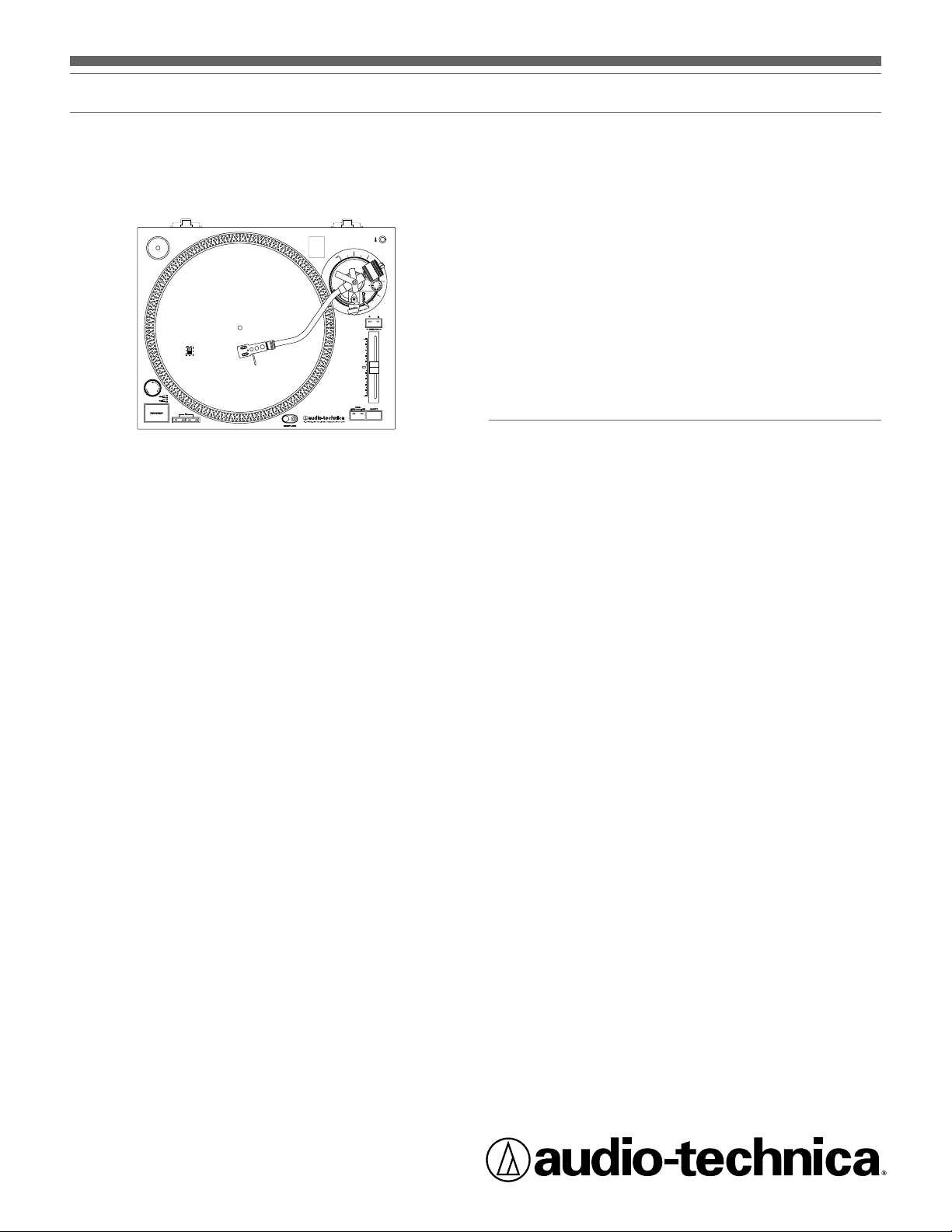
AT-LP120-USB Direct-Drive Professional USB and Analog Turntable System
Installation and Operation Pages 2-10
AT-LP120-USB
Système de tourne-disque USB professionnel à
entraînement direct
Installation et utilisation Pages 11-20
AT-LP120-USB
Sistema tocadiscos USB profesional con
accionamiento directo
Instalación y funcionamiento Páginas 21-30
Direct-Drive Professional USB and Analog Turntable System
Safety instructions
1. Read these instructions.
2. Keep these instructions.
3. Heed all warnings.
4. Follow all instructions.
5. Do not use this apparatus near water.
6. Clean only with a dry cloth.
7. Do not block any of the ventilation openings. Install in accordance
with the manufacturer’s instructions.
8. Do not install near any heat sources such as radiators, heat registers,
stoves, or other apparatus (including amplifiers) that produce heat.
9. Do not defeat the safety purpose of the polarized or grounding
plug. A polarized plug has two blades with one wider than the other.
A grounding plug has two blades and a third grounding prong. The
wide blade or the third prong is provided for your safety. If the
provided plug does not fit into your outlet, consult an electrician for
replacement of the obsolete outlet.
10. Protect the power cord from being walked on or pinched particularly
at plugs, convenience receptacles, and the point where they exit
from the apparatus.
11. Only use attachments/accessories specified by the manufacturer.
12. Use only with a cart, stand, tripod, bracket or table specified by
the manufacturer, or sold with the apparatus. When a cart is used,
use caution when moving the cart/apparatus combination to avoid
injury from tip-over.
13. Unplug this apparatus during lightning storms or when unused for
long periods of time.
14. Refer all servicing to qualified service personnel. Servicing is
required when the apparatus has been damaged in any way, such
as power-supply cord or plug is damaged, liquid has been spilled or
objects have fallen into the apparatus, the apparatus has been
exposed to rain or moisture, does not operate normally, or has
been dropped.
15. Where a mains plug is used as the disconnect device, the
disconnect device shall remain readily operable.
16. Please keep the unit in a good ventilation environment.
17. Apparatus shall not be exposed to dripping or splashing and
no objects filled with liquids, such as vases, shall be placed
on apparatus.
Warning: To reduce the risk of fire or electric shock, do not
expose this apparatus to rain or moisture. The apparatus shall not
be exposed to dripping or splashing and that no objects filled with
liquids, such as vases, shall be placed on the apparatus.
CAUTION
RISK OF ELECTRIC SHOCK
DO NOT OPEN
Caution: To reduce the risk of fire or electric shock, do not expose
this apparatus to rain or moisture. The apparatus shall not be
exposed to dripping or splashing, and no objects filled with liquids,
such as vases, shall be placed on the apparatus.
The lightning flash with arrowhead symbol within the
equilateral triangle is intended to alert the use to the
presence of uninsulated “dangerous voltage” within
the product’s enclosure that may be of sufficient
magnitude to constitute a risk of electric shock.
Introduction
Thank you for purchasing the AT-LP120-USB Direct-Drive Professional
USB and Analog Turntable System. Audio-Technica brings its legendary
quality and audio fidelity to the digital realm with this LP-to-digital
recording system. In the box, you’ll find everything you need to transfer
your classic LP collection to digital files: Audio-Technica’s AT-LP120USB stereo turntable, complete with USB output that allows direct
connection to your computer; Audacity recording software for MAC
or PC; an integral dual-magnet Audio-Technica phono cartridge; a USB
cable and adapter cables. The turntable also offers a built-in switchable
phono/line preamp that allows connection to a stereo system equipped
with either a phono or line-level input.
The AT-LP120-USB Direct-Drive Professional USB and Analog Turntable
System features the following:
• USB output—no special drivers required for direct connection to
your computer
• Direct drive high-torque motor
• Selectable 33/45/78 RPM speeds
• Selectable internal stereo phono pre-amplifier
• S-shaped tone arm assembly with:
•
Adjustable counterweight
•
Anti-skate adjustment
•
Tone arm height adjustment and lock
•
Tone arm lift with hydraulic action and lift lever
•
Tone arm rest with locking mechanism
• Selectable high-accuracy quartz-controlled pitch lock
• Selectable +/–10% or +/– 20% pitch adjustment ranges
• Stroboscopic platter speed indicator
• Forward and reverse play
• Cast aluminum record platter with slip mat
• Start/stop button
• Pop-up stylus target light
• 45-RPM adapter with storage receptacle
• Receptacle for extra headshell
• Adjustable feet for leveling
• Removable hinged dust cover
To assure maximum satisfaction from this product, please read the
information and follow the instructions presented in this manual. Please
keep the manual in an accessible location for future reference. We
suggest that you save all the packaging materials for possible future
storage, moving, or shipping.
Caution: To avoid stylus damage, make certain the included stylus
guard is in place whenever the turntable is being installed, moved,
or cleaned.
The exclamation point within the equilateral triangle is
intended to alert the user to the presence of important
operation and maintenance (servicing) instructions in
the literature accompanying this appliance.
Caution: To prevent electric shock, do not use this polarized plug
with an extension cord, receptacle or other outlet unless the blades
can be fully inserted to prevent blade exposure.
2
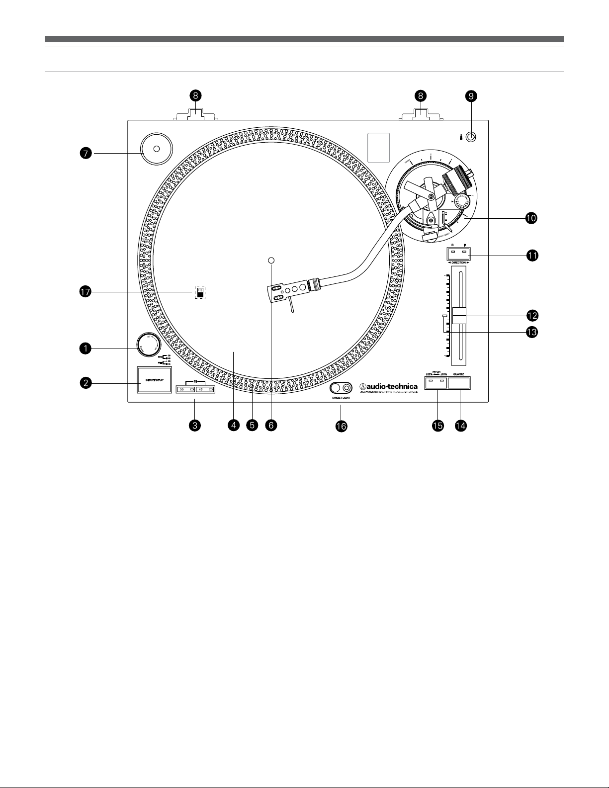
Figure 1
English
Main Features
1. POWER DIAL
Controls power to the unit.
2. START/STOP BUTTON
Engages and disengages the motor/platter.
3. PLATTER SPEED BUTTONS
Select 33 or 45 RPM platter speed. (Note: 78 RPM is selected by
pressing the 33 and 45 buttons simultaneously.)
4. PLATTER
Cast aluminum platter mounts directly to center
spindle/motor shaft.
5. STROBE DOTS (On platter edge)
Operate in conjunction with stroboscopic light located under
power dial (1) to provide visual indication of accurate platter speeds.
6. CENTER SPINDLE
Precision-machined platter mount on motor shaft.
7. 45-RPM ADAPTER (Shown in receptacle)
Adapts 7" records with large center holes to fit center spindle.
8. DUST COVER HINGE HOLDERS
Attachment points for removable hinged dust cover.
9. HEADSHELL RECEPTACLE
Storage receptacle for extra headshell (not included).
10. TONE ARM ASSEMBLY
Refer to Figure 2 on page 4 for details.
11. DIRECTION BUTTON
Controls platter’s rotational direction:
F – Forward (clockwise)
R – Reverse (counter-clockwise)
12. PITCH ADJUST SLIDE CONTROL
Use in conjunction with pitch button (15) to vary the platter’s
rotational speed. In the center detent position quartz lock is active.
13. PITCH SELECTION INDICATOR
Shows Green for standard or locked RPM setting, or Red for a
pitch-adjusted setting.
14. QUARTZ SPEED LOCK
Toggles between internal quartz-locked reference and variable
pitch controlled by pitch adjust slide control (12).
15. PITCH BUTTON
Selects the range of pitch variation permitted by the pitch adjust
slide control (12). (See page 7 for information on locking or
adjusting platter speed.)
16. POPUP STYLUS TARGET LIGHT
Provides illumination directed at the stylus position for easier
cueing in poor light.
17. VOLTAGE SELECTOR SWITCH
(Access through holes in platter)
Selects operating voltage (115V or 230V AC, 60/50 Hz).
3
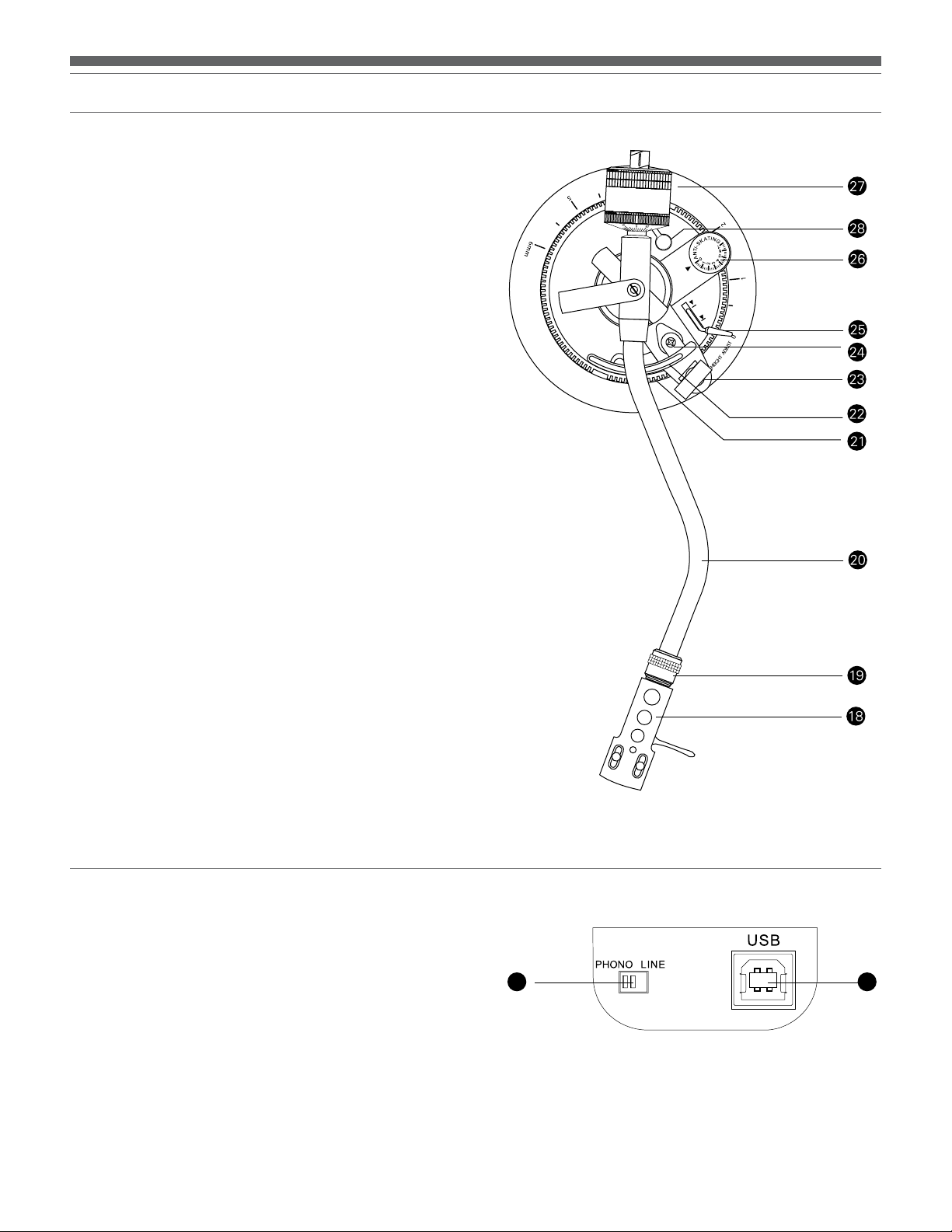
Tone Arm Assembly Diagram
Figure 2
18. HEADSHELL
Standard, interchangeable stereo cartridge headshell.
19. HEADSHELL LOCKING RING
Rotate counter-clockwise (to the left) to draw the inserted
headshell firmly into its seated, locked position. Rotate the ring
a full turn to the right to permit removal of the headshell.
20. TONE ARM
S-shaped tone arm geometry reduces tracking error.
21. TONE ARM ASSEMBLY HEIGHT ADJUST
Raises and lowers the entire tone arm assembly to allow the tone
arm to remain parallel to the record surface. (The proper setting
is “0” for the included cartridge.)
22. TONE ARM LIFT
Elevates tone arm above record surface.
23. TONE ARM REST WITH LOCKING CLAMP
Locking clamp secures tone arm during transport.
24. TONE ARM LIFT ADJUST SCREW
Used to set the amount of tone arm lift.
25. TONE ARM LIFT CONTROL LEVER (“Cueing Lever”)
Controls action of tone arm lift. (Note: Lift mechanism is
hydraulically damped to slow tone arm descent.)
26. ANTI-SKATE CONTROL
Applies a small outward force to the tone arm, counteracting the
tendency of the tone arm to move inward toward the center of
the record.
27. COUNTERWEIGHT
Balances the tone arm and provides adjustment for proper
downward tracking force on the stylus.
28. TONE ARM ASSEMBLY HEIGHT LOCK
(Hidden under counterweight in drawing)
Locks the tone arm height setting. (Always fully unlock
before attempting to make a height adjustment.)
Rear View Diagram
Figure 3
29. PRE-AMP SELECTOR SWITCH
Allows the internal stereo phono pre-amp to be bypassed
when the turntable is used with equipment having
magnetic phono inputs.
30. USB OUTPUT
Use this output to connect your turntable to the USB input of
your computer. Please see included software guide for
instructions.
3029
4
English
Initial Setup
Unpacking
Carefully unpack the turntable and verify that the following parts are
included and intact:
• Slip mat (above the dust cover)
• Dust cover (above the turntable)
• Platter (under the turntable)
• Dust cover hinges (accessory section of the
foam packaging)
• 45 RPM adapter (accessory section)
• Counterweight (accessory section)
• Headshell with pre-mounted cartridge
(accessory section)
• Power cord (accessory section)
• USB cable
• Dual RCA (female) to 3.5 mm (1/8") mini-plug (male)
stereo adapter cable
• Dual RCA (female) to 3.5 mm (1/8") mini-plug (female)
stereo adapter cable
• Audacity software (CD)
WE RECOMMEND THAT YOU SAVE ALL PACKAGING
MATERIALS FOR POSSIBLE FUTURE STORAGE, MOVING OR
SHIPPING.
Assembling the Turntable
The AT-LP120-USB requires some assembly before first use.
IMPORTANT: Do not connect the AC power cord until assembly is
complete.
Setting the Voltage Selector Switch
This turntable has the capability to be used with either 115V or 230V
AC power, 60/50 Hz. The voltage selector switch is located on the
top of the housing deck, under the platter. Set the switch according
to the voltage in your area. [See Figure 4.] (Note: The turntable comes
shipped with the voltage selector switch set for 115V AC.)
When using the turntable with a computer sound card, set the switch
to LINE OUT and connect the turntable to the audio line input on the
computer sound card. Note: An audio adapter (not included) may be
required to interface the two RCA jacks of the turntable output cable to
the computer sound card input.
Assembling the Tone Arm
(Note: The headshell and cartridge are supplied pre-assembled with the
AT-LP120-USB.)
1. Remove the vinyl tie used to secure the tone arm during
shipment. Temporarily secure the tone arm in the tone arm
rest with the locking clamp. [Figure 2, page 4, #23.]
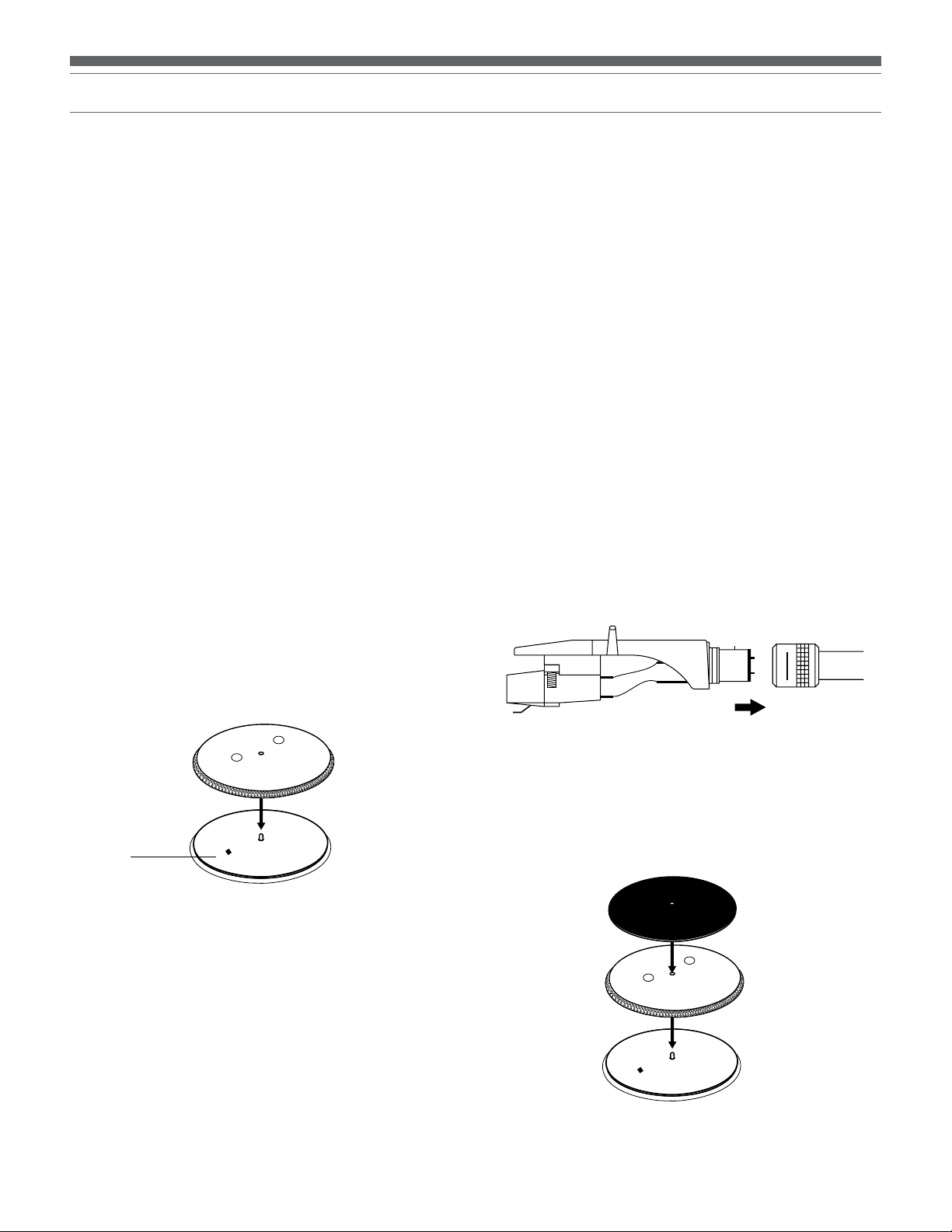
2. Attach the headshell assembly by inserting it into the
socket at the front of the tone arm [See Figure 5.] (It’s
good practice always to hold a headshell assembly by the
left and right edges of the headshell to reduce the
possibility of damaging the stylus or disrupting the
cartridge wiring.)
3. While holding the headshell in position, rotate the
headshell locking ring counter-clockwise (to the left).
As the ring turns, it pulls the headshell into its seated
position. (Rotate the ring a full turn to the right to permit
removal of the headshell.)
4. With its black dial toward the front, use a screwing motion
to attach the counterweight to the arm extending back
from the tone arm pivot [Figure 2, page 4, #27]; the
counterweight will engage the spiral groove in the rear arm
section and move forward.
Figure 5 – Headshell
Figure 4 – Voltage Switch
Voltage
switch
Setting the Pre-amp Selector Switch
For increased flexibility of use, this turntable has an internal stereo
phono pre-amplifier. The pre-amp selector switch located in the rearpanel of the turntable [See Figure 3, page 4, #29], selects the internal
stereo pre-amplifier (LINE OUT), or bypasses the pre-amp (PHONO
OUT) for use with systems having specialized magnetic phono input
jacks. The audio output cable’s Red RCA-type plug is the Right channel;
the White plug is the Left channel.
If the system you are using has a PHONO input, set the pre-amp
selector switch to the PHONO OUT position and connect the
turntable’s output cables to the PHONO inputs on your system,
observing Red for Right channel and White for Left channel.
If your system does not have a PHONO (magnetic phono) input, set the
pre-amp selector switch to LINE OUT and connect the turntable’s output
cables to the Auxiliary (AUX) or other high-level inputs on your system,
observing Red for Right channel and White for Left channel.
Assembling the Turntable Platter and Slip Mat
1. Carefully place the turntable platter on the center spindle,
making certain the platter is fully seated on the spindle.
[See Figure 6.]
2. Place the soft black slip mat on top of the platter.
Figure 6 – Platter and Slip Mat
5

Initial Setup (continued)
Assembling the Dust Cover
1. Insert the T-shaped ends of the dust cover hinges into the two
hinge receptacles located at the back of the turntable housing.
When properly installed, the flat part of the cover hinges should be
facing away from the turntable housing at about a 45° angle.
2. Holding the dust cover over the turntable, carefully guide the cover
hinges into the two slots molded into the rear of the dust cover.
The springs in the hinges allow the cover to be held open at about
a 45° angle if desired. (Note: There is only one “open” position;
the hinges do NOT permit the cover to stand “straight up.”)
3. To remove the dust cover from the turntable, gently disengage the
hinges from the slots in the cover. This is usually easier when the
cover is in the “closed” position. Slowly and carefully lift straight
up until the cover is clear of the unit. The hinges may then be
removed from the turntable base, if desired.
Setting Tone Arm Balance and Tracking Force
To allow the cartridge to properly track in a record, the tone arm
balance and tracking force must be carefully set to the cartridge
manufacturer’s specifications. Failure to properly set up the tone arm
assembly can cause damage to the cartridge stylus and/or records.
(Note: Once the stylus protective cover has been removed and the tone
arm locking clamp has been released, take extreme care not to damage
the stylus. Do not allow it to drag or scrape across the slip mat.)
Tone Arm Setup:
1. Set the anti-skate adjustment to “0”. [Figure 2, page 4, #26.]
2. Remove the clear protective stylus cover, carefully sliding it
straight forward, off the front of the cartridge.
3. While gently holding the headshell to stabilize the tone arm,
release the tone arm locking clamp. At this point, the tone arm is
unbalanced and free to swing.
4. While gently holding the headshell, carefully rotate the
counterweight until the tone arm is horizontally balanced and
hovers freely just above the platter without touching the platter
surface.
5. Lock the tone arm back into the tone arm rest.
6. While holding the counterweight steady, and without any rotation,
carefully rotate only the black stylus force gauge ring (which turns
independently of the counterweight) until the “0” on the gauge ring
lines up with the centerline marked along the top of the rear arm.
7. Refer to the cartridge manufacturer’s specifications for
recommended tracking force. Rotate the entire counter-weight
counterclockwise without touching the black gauge ring, moving
the counterweight forward, until the desired value on gauge ring
lines up with the centerline marked on the rear arm. Refer to the
specifications section for tracking force value for the cartridge that
shipped with the turntable.
Setting Anti-skate
A small outward “anti-skating” force can be applied to the tone arm
to compensate for the “skating” force that pulls the arm toward the
center of the record. For best performance during normal turntable
use, set the anti-skate control knob [Figure 2, page 4, #26] to the same
setting as the tracking force dial. Refer to the specifications section for
tracking force value of the cartridge that shipped with the turntable.
The tone arm assembly height adjustment allows for the tone arm
to be positioned parallel to the record surface, when using extra-tall
cartridge bodies, thick slip mats or thick records (i.e. old 78’s). To raise
or lower the tone arm assembly: First, loosen the height lock [Figure 2,
page 4, #28]; then rotate the height adjust dial [Figure 2, page 4, #21]
located at the base of the tone arm assembly. The scale is calibrated in
millimeters (mm). When finished, tighten the height lock to secure the
adjustment.
Connections
Audio
Connect the audio output cable to the appropriate input jacks on your
mixer, amplifier, soundcard or other device based on the setting of the
pre-amp selector switch. Firmly connect the Red RCA-type plug to the
right channel input and the White RCA-type plug to the left channel
input. (Note: Adapter plugs might be required to connect the turntable
to computer sound cards and other devices.)
Connecting to Computers with USB Input
The USB cable (included) connects your AT-LP120-USB turntable to
your computer without need for special drivers. Refer to included
software guide (also available online at www.audio-technica.com)
before connecting the turntable to your computer.
Connecting to Computers or Audio Devices with 3.5 mm Input
The AT-LP120-USB connects without adapters to devices equipped with
RCA connectors. For maximum flexibility, we have included two adapter
cables to fit other popular audio inputs.
The first of these adapter cables – dual RCA to stereo 3.5 mm mini-plug
(male) – is designed to fit most popular computer* audio inputs. It may
also be used to connect the turntable’s RCA output to other equipment,
including:
• a stereo/boombox* equipped with a 3.5 mm minijack
• input powered speakers* equipped with a 3.5 mm minijack
• input a mixer* or PA system* equipped with a 3.5 mm minijack
The second included adapter cable – dual RCA to stereo 3.5 mm miniplug (female) – permits connection of the turntable output to amplified
speakers* or similar devices. The 3.5 mm stereo minijack on the cable
adapter accepts stereo mini-plugs.
To use either adapter cable, connect the turntable’s red and white RCAtype plugs to the cable adapter’s RCA-type jacks.
* When using either cable adapter, always set the AT-LP120-USB
turntable’s Pre-amp Selector Switch to the “LINE” position.
(Switch is located on the back of the turntable.)
NOTE: If connection is desired to a mono amplifier/speaker, make
certain to use a stereo-to-mono adapter, available from your dealer or
an electronic parts store. Inserting a mono plug in the stereo jack will
disable one of the stereo channels. Other adapter cable configurations
will be available from dealers and parts stores for connecting to devices
needing different terminations.
Finally, after all other connections are made, attach the included AC
power cord to the turntable; note that the small connector only goes
in one way. Then connect the power cord’s plug to a convenient AC
outlet.
In case of substantial use of back-cueing, scratching or reverse-direction
operation, you may prefer to use less, or no, anti-skate compensation.
Setting Tone Arm Assembly Height
6

English
Operation
For best results, do not install or operate this unit near conditions of
heat, moisture, dust, or heavy vibrations. (Note: Bright fluorescent lights
may affect the visibility of the speed-indicating strobe dots. If this is a
problem, simply cover the area with your hand, an album cover, etc.)
Preparing to Play
1. Remove the stylus guard from the stylus assembly and unlock the
tone arm rest if it is locked.
2. Turn the power dial to the ON position. The speed selector and
strobe illuminator will light up.
3. If desired, push the stylus target light button to raise and turn on
the light for illumination of the stylus tip position on the record.
4. Place a record on the slip mat, lining up its center hole with the
center spindle. For 45RPM records, place the 45 RPM adapter on
the center spindle before placing the record on the platter.
5. Set the platter rotation speed (33/45/78) to match that of the
record. (Note: To set the platter speed for 78 RPM, push both the
33 and 45 RPM buttons simultaneously.)
Playing the Record
1. Press the start/stop button; the platter begins to rotate.
2. Raise the tone arm by lifting the tone arm lift control lever to the
UP position.
3. Position the tone arm over the desired location (groove) on
the record.
4. Lower the tone arm by moving the tone arm lift control lever to
the DOWN position. The tone arm descends slowly onto the
record and play begins.
– or –
Use the finger-lift on the headshell assembly to position the tone
arm over the desired location on the record. Carefully lower the
tone arm to the record surface.
Checking and Adjusting Pitch
1. If desired, select a +/– 10% or +/– 20% pitch adjustment range by
pressing the pitch button. Then move the pitch adjust slide control
up or down to make pitch adjustments. (Note: The pitch adjust
slide control has center detent position for 0% pitch variation.)
2. As illuminated by the red light coming from beneath the power
dial, observe the strobe dots on the edge of the platter. If the
appropriate row of strobe dots appears to be stationary, the platter
is moving at the precise rated speed. If the dots appear to be
moving to the right, the platter is moving below rated speed; if
they appear to be moving to the left, the platter is moving above
rated speed.
50Hz
3. If the quartz speed lock button is pressed, the internal quartz lock
will hold the platter at precise rated speed regardless of the
position of the pitch adjust slide control. (Note: The LED indicator
to the left of the pitch adjust slide control’s center position will
illuminate GREEN when the quartz lock is active and RED when
variable pitch is active.)
4. If desired, press the direction button to reverse the rotation of the
platter. The appropriate direction LED will illuminate.
Suspending or Ending Play
1. To suspend play, lift the tone arm with the cueing lever.
2. When play is finished, raise the cueing lever, move the tone arm
to the rest position and secure the tone arm with the tone arm
locking clamp.
3. If using the stylus target light, turn it off by pushing the
light down.
4. Press the start/stop button to apply the brake and stop the
platter rotation.
5. Turn the power dial to the OFF position.
33
45
60Hz
33
45
7
Replacing the Stylus
Replacing the Stylus
The AT-LP120-USB comes supplied with a high-quality Audio-Technica
ATP-2 cartridge. The stylus should be replaced with a genuine
Audio-Technica ATP-N2 stylus.
1. Release the headshell assembly from the tone arm by turning the
locking ring clockwise.
2. Carefully remove the headshell assembly and turn it over so the
stylus is visible.
3. Remove the stylus assembly by pulling it away from the cartridge
body at a slight angle. [See Figure 7.]
4. Remove the replacement stylus from its package and carefully
align it with the cartridge body.
Replacing the Cartridge
Mechanical Assembly
1. To replace the cartridge, first release the headshell assembly from
the tone arm by turning the locking ring clockwise. Carefully
remove the headshell assembly and turn it over so that the stylus
is visible. Remove the stylus assembly by pulling it away from the
cartridge body at a slight angle. [See Figure 7.] Place the stylus
assembly out of harm’s way.
2. Remove the cartridge body by loosening the two small screws
securing the cartridge to the headshell. Set the hardware aside to
be reused with the new cartridge.
3. Unpack the new cartridge and carefully remove its stylus
assembly. Place the stylus assembly out of harm’s way. Mount
the new cartridge to the headshell assembly. Use the mounting
hardware supplied with the new cartridge or the existing hardware
removed at step 2. Tighten the mounting screws until just snug.
Replace the stylus assembly briefly to check for mechanical
interference with the mounting hardware. The stylus assembly
should click into place. Make certain the new cartridge is properly
positioned in the headcase assembly per the manufacturer’s
instructions. Again remove the stylus assembly for safekeeping.
5. Gently push the stylus onto the cartridge body, being careful not to
damage the stylus. The stylus assembly should click into place.
6. Replace the headshell assembly on the tone arm and secure with
the locking ring.
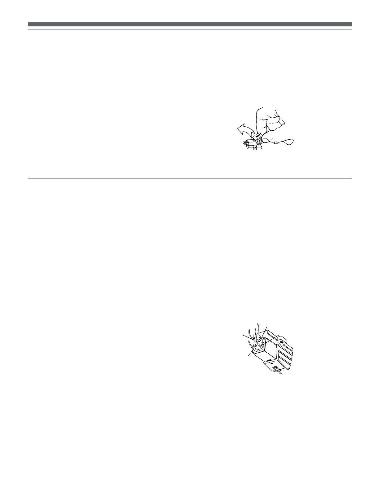
Figure 7 – Removing the Stylus
Electrical Connections
1. Four terminals at the rear of the cartridge are color coded to match
standard wiring in stereo tone arms. [See Figure 8.] Connect the
cartridge with the slip-on lugs provided on the headshell wiring.
NEVER SOLDER TO CARTRIDGE TERMINALS! Heat applied to
the terminals will damage the internal cartridge wiring.
2. For monaural operation, the left and right signal leads should be
connected to the monaural output terminal and the left and right
ground leads should be connected to the ground terminal.
3. Finally, gently push the stylus onto the cartridge body being
careful not to damage the stylus. The stylus assembly should click
into place. Replace the headshell assembly onto the tone arm
taking care not to damage the stylus assembly.
(Note: After replacing the cartridge, reset the tone arm balance, stylus
force and anti-skate based on the new cartridge’s specifications.)
Figure 8 – Electrical Connections
Right Output
(Red)
Left Output
(White)
Right Ground
(Green)
Left Ground
(Blue)
8

English
Troubleshooting
Turntable operates but emits no sound or not enough sound.
1. The stylus guard is still in place. Remove the stylus guard.
2. The tone arm is in the lift position. Lower the tone arm.
3. Mixer/amplifier (system) controls are set incorrectly: wrong input
selected, tape monitor on, speakers switched off, etc. Verify
proper control settings.
4. Stylus is broken or missing. Check the stylus assembly and
replace if necessary.
5. The stylus assembly may not be fully seated in the cartridge body.
Check the cartridge and adjust if necessary.
6. The pre-amp selector switch is set in the wrong position. Verify
that it is set for proper output to match mixer/amplifier.
- No sound/very weak sound: Phono Out setting into an
Aux/Line input.
- Very loud/distorted sound: Line Out setting into a
Phono input.
Turntable operates but stylus “skips” across record.
1. The stylus guard is still in place. Remove the stylus guard.
2. The tracking force is set too light. Set tracking force per cartridge
manufacturer’s recommendation.
3. The tracking force is set too heavy (stylus assembly is bottoming
out on record). Set tracking force per cartridge manufacturer’s
recommendation.
Record sounds too fast or too slow.
1. Turntable is set for wrong speed. Make proper speed selection for
record type being played with platter speed buttons.
2. Variable pitch is engaged. Depress quartz button or return pitch
adjust slider to center detent position to engage quartz lock.
Moving pitch adjust slider produces no effect.
If the LED next to the pitch adjust slider center detent position remains
green when the slider is moved, quartz lock is engaged. Depress the
quartz button to disengage the quartz lock and activate variable pitch.
The LED should turn RED.
Strobe dots are difficult to see and/or stylus illuminator is very
dim.
1. Excessively bright or fluorescent light interferes with strobe
indicator. Hold hand, record jacket, etc. over strobe indicator to
shield it from bright light.
2. Voltage selector switch is set for 230V when AC mains are 115V.
Disconnect AC power cord and reset the voltage selector switch
located under the platter. (Note: Even with the voltage selector
set for 230V when AC mains are 115V, the quartz lock will bring
the platter up to proper speed.)
4. The anti-skate control is set improperly. Verify anti-skate is set for
same value as cartridge tracking force.
5 Turntable is picking up excessive vibrations from floor, walls, or
nearby speakers. Reduce vibrations or place turntable on sturdy/
solid surface.
Tips For Better Performance
• When opening or closing the turntable cover, handle it gently,
moving it either at the center or equally from both sides.
• Do not touch the stylus tip with your fingers; avoid bumping
the stylus on the turntable mat or a record’s edge.
• Clean the stylus tip frequently, using a soft brush and a back-
to-front motion.
• If you use a stylus cleaning fluid, use it sparingly.
• Wipe the dust cover and turntable housing gently with a soft
cloth. Use only a small amount of mild detergent solution to
clean the turntable and dust cover.
• Never apply harsh chemicals or solvents to any part of the
turntable system.
• Prior to moving the turntable, always unplug it from the AC
outlet and lock the tone arm on the tone arm rest.
9

Specications
†
Turntable Specifications
Type 3-Speed, fully manual operation
Motor DC motor
Drive method Direct drive
Speeds 33-1/3 RPM, 45 RPM, 78 RPM
Pitch variation +/- 10% or +/- 20%
Turntable platter Die-cast aluminum
Starting torque >1.6 kgf.cm
Braking system Electronic brake
Wow and flutter < 0.2% WRMS (33 RPM)
Signal-to-noise ratio > 50 dB
Output level
Pre-amp “PHONO” 2.5 mV nominal at 1 kHz, 5 cm/sec
Pre-amp “LINE” 150 mV nominal at 1 kHz, 5 cm/sec
Phono pre-amp gain 36 dB nominal, RIAA equalized
USB function
A/D, D/A 16 bit 44.1 kHz or 48 kHz USB selectable
Computer interface USB 1.1 Compliant Windows XP, Vista or
MAC OSX
Power supply 115/230V AC, 60/50 Hz
requirements
Power consumption 11W
Dimensions 450.0 mm (17.72") W x 352.0 mm
(13.86") D x 157.0 mm (6.1") H
Weight 10.7 kg (23.5 lbs.)
Accessories included Headshell/cartridge (ATP-2); AC line cord;
dual RCA (female) to 3.5 mm (
plug (male) stereo adapter cable; dual
RCA (female) to 3.5 mm (
(female) stereo adapter cable; 45 RPM
adapter; USB cable; recording software
Replacement stylus ATP-N2
1
/8") mini-
1
/8") mini-plug
Cartridge Specifications (ATP-2)
Frequency response 15 – 22,000 Hz
Channel separation 23/17 (dB at 1 kHz/10 kHz)
Vertical tracking force 3.0 – 5.0 grams
Stylus construction Bonded round shank
Output 5.3 mV at 1 kHz, 5 cm/sec
Channel balance 1.5 dB
Stylus shape 0.4 x 0.7 mil elliptical
Cantilever Alloy tube
Mount Half-inch
†
Specications are subject to change without notice.
10

Français
AT-LP120-USB Système de tourne-disque USB professionnel à entraînement direct
Installation et utilisation Pages 11-20
11

Système de tourne-disque USB professionnel à entraînement direct
Instructions de sécurité
1. Veuillez lire les instructions ci-dessous.
2. Conservez-les.
3. Tenez compte de tous les avertissements.
4. Suivez toutes les instructions.
5. N’utilisez pas l’appareil à proximité de l’eau.
6. Nettoyez-le uniquement avec un chiffon sec.
7. N’obstruez aucun des orifices de ventilation. Installez l’appareil en
suivant les instructions du fabricant.
8. Ne le placez pas à proximité de toute source de chaleur telle qu’un
radiateur, une grille de chauffage, un poêle ou tout autre appareil (y
compris un amplificateur) produisant de la chaleur.
9. Ne retirez pas l’option de sécurité de la fiche polarisée ou de mise
à la terre. Une fiche polarisée comporte deux lames dont une est
plus large que l’autre. Une fiche de mise à la terre possède deux
lames et une troisième broche de mise à la terre. La lame large ou
la troisième broche assure la sécurité de l’utilisateur. Si la fiche
fournie ne s’adapte pas à la prise électrique, demandez à un
électricien de remplacer la prise hors normes.
10. Protégez le cordon d’alimentation afin que personne ne marche
dessus et que rien ne le pince, en particulier au niveau des fiches,
des prises de courant et du point de sortie de l’appareil.
11. Utilisez uniquement les accessoires spécifiés par le fabricant.
12. N’utilisez l’appareil qu’avec un chariot, un pied, un trépied,
un support ou une table spécifiés par le fabricant ou vendus avec
l’appareil. Si un chariot est utilisé, déplacez l’ensemble chariot appareil avec précaution afin de ne pas le renverser, ce qui pourrait
entraîner des blessures.
13. Débranchez l’appareil en cas d’orage ou de non-utilisation prolongée.
14. Confiez tout entretien à une personne qualifiée. Un entretien est
nécessaire lorsque l’appareil a été endommagé de quelque façon
que ce soit, par exemple en cas de détérioration du cordon ou de la
prise d’alimentation, de renversement de liquide ou de chute
d’objets à l’intérieur de l’appareil, d’exposition de l’appareil à la pluie
ou à l’humidité, de fonctionnement anormal ou de chute de
l’appareil.
15. Si une prise secteur est utilisée comme dispositif de
débranchement, ce dernier doit toujours être opérationnel.
16. Conservez l’appareil dans un environnement bien aéré.
17. L’appareil ne doit pas être exposé à des égouttements d’eau ou
des éclaboussures et aucun objet rempli de liquide, tel qu’un vase,
ne doit être placé sur l’appareil.
Attention : afin de réduire les risques d’incendie ou de choc
électrique, n’exposez pas l’appareil à la pluie ou à l’humidité.
L’appareil ne doit pas être exposé à des égouttements d’eau ou des
éclaboussures et aucun objet rempli de liquide, tel qu’un vase, ne
doit être placé sur l’appareil.
RISQUE DE CHOC ÉLECTRIQUE
ATTENTION
NE PAS OUVRIR
Attention : afin de réduire le risque de choc électrique, ne retirez
pas le couvercle. L’appareil ne comporte aucune pièce réparable
par l’utilisateur. Confiez l’entretien de l’appareil uniquement à un
personnel qualifié.
Le symbole de l’éclair avec une pointe de flèche dans
un triangle équilatéral est destiné à prévenir l’utilisateur
de la présence à l’intérieur du boîtier d’une « tension
dangereuse » non isolée dont la magnitude peut être
suffisante pour constituer un risque de choc électrique.
Le point d’exclamation dans un triangle équilatéral
a pour but d’avertir l’utilisateur de la présence
d’importantes instructions de fonctionnement et de
maintenance (entretien) dans la documentation fournie
avec l’appareil.
Introduction
Merci d’avoir choisi le système de tourne-disque USB professionnel
à entraînement direct AT-LP120-USB. Ce système d’enregistrement
numérique pour microsillons vous permet de bénéficier de la légendaire
qualité et de la haute fidélité Audio-Technica en transposant vos
enregistrements sur vinyles dans le monde numérique. Dans cette
boîte, vous trouverez tout ce qui est nécessaire pour convertir la
musique de vos microsillons classiques en fichiers numériques : le
tourne-disque stéréo Audio-Technica AT-LP120-USB, muni d’une
sortie USB pour une connexion directe à votre ordinateur, les logiciels
d’enregistrement Audacity (pour MAC ou PC), une cellule phono AudioTechnica Integral Dual-Magnet, un câble USB et des câbles adaptateurs.
Le tourne-disque est également muni d’un préamplificateur commutable
phono/ligne intégré qui permet de le brancher sur un système stéréo
équipé d’une sortie phono ou ligne.
Caractéristiques du système de tourne-disque USB professionnel à
entraînement direct AT-LP120-USB :
• Sortie USB - aucun gestionnaire de périphérique n’est nécessaire
pour relier le tourne-disque directement à votre ordinateur
• Moteur à couple élevé à entraînement direct
• Trois vitesses au choix : 33, 45 et 78 tr/min
• Préamplificateur phono stéréo interne
• Bras de lecture en forme de S doté :
•
d’un contrepoids ajustable
•
d’un réglage de la compensation de la force centripète
•
d’un réglage et d’un calage de la hauteur du bras de lecture
•
d’un levier de levage du bras de lecture à action hydraulique
•
d’un support de bras de lecture avec mécanisme de blocage
• Verrouillage optionnel de la hauteur tonale, piloté par quartz de
haute précision
• Plages de réglage optionnel de la hauteur tonale de +/-10 %
ou +/-20 %
• Indicateur stroboscopique de vitesse de la platine
• Lecture en marche avant et arrière
• Platine professionnelle en fonte d’aluminium avec tapis antidérapant
• Bouton de marche/arrêt
• Éclairage de positionnement de la pointe de lecture
• Adaptateur 45 tr/min avec logement de rangement
• Logement pour une tête de lecture de rechange
• Pied réglable pour la mise à niveau
• Couvercle pare-poussière amovible à charnières
Pour utiliser ce produit à votre meilleure satisfaction, lisez les
informations et suivez les instructions données dans ce manuel. Gardez
le manuel à un endroit accessible pour pouvoir le consulter aisément
lorsque vous en aurez besoin.
Nous vous recommandons de garder tous les emballages pour
entreposer, déplacer ou transporter l’appareil au besoin.
ATTENTION : Pour éviter les risques de dommage à la pointe de
lecture, veillez à ce que la protection fournie est en place lorsque
vous installez, déplacez ou nettoyez le tourne-disque.
12
Attention : pour éviter tout choc électrique, n’utilisez pas cette
fiche polarisée avec un cordon prolongateur, un connecteur
femelle ou une autre prise, sauf si les lames peuvent s’insérer
complètement afin d’empêcher leur exposition.

Figure 1
Français
Principale caractéristique
1. SÉLECTEUR DE MISE SOUS TENSION
Commande l’alimentation du tourne-disque.
2. BOUTON DE MARCHE/ARRÊT
Pour la mise en marche et à l’arrêt du moteur/de la platine.
3. SÉLECTEUR DE VITESSE DE ROTATION DE LA PLATINE
Pour choisir entre 33 et 45 tr/min (Remarque : Pour sélectionner
78 tr/min, appuyer simultanément sur les boutons 33 et 45 tr/min.)
4. PLATINE
Platine en fonte d’aluminium montée directement sur l’axe
moteur.
5. POINTS STROBOSCOPIQUES (sur la périphérie de la platine)
Ils interagissent avec la lumière stroboscopique située sous le
sélecteur de mise sous tension (1) pour fournir une indication
visuelle de la vitesse de rotation correcte de la platine.
6. AXE CENTRAL
Prolongeant l’axe ; pièce à usinage de précision.
7. ADAPTATEUR 45 TR/MIN (placé dans son logement sur
l’illustration)
Pour maintenir autour de l’axe central les disques de 17 cm à
trou large.
8. LOGEMENTS DES CHARNIÈRES DU COUVERCLE
ANTI-POUSSIÈRE
Points de fixation des charnières du couvercle anti-poussière.
9. LOGEMENT POUR TÊTE DE LECTURE
Logement pour une tête de lecture de rechange (non fournie).
10. ENSEMBLE BRAS DE LECTURE
Cf. page 14, figure 2 pour plus de détails.
11. BOUTON DE DIRECTION
Commande la direction de rotation de la platine :
F – Forward, marche avant (dans le sens des aiguilles d’une montre)
R – Reverse, marche arrière (dans le sens inverse des aiguilles
d’une montre)
12. CURSEUR DE RÉGLAGE DE HAUTEUR TONALE
S’utilise conjointement au bouton de commande de hauteur
tonale (15) pour ajuster le réglage fin de la vitesse de rotation de
la platine. L’asservissement par quartz est actif lorsque la position
du curseur correspond à celle du cran central.
13. INDICATEUR DE SÉLECTION DE HAUTEUR TONALE
S’allume en vert lorsque la vitesse de rotation correspond au
réglage standard ou asservi ; s’allume en rouge pour un réglage
personnalisé de la vitesse de rotation.
14. ASSERVISSEMENT PAR QUARTZ DE LA VITESSE DE ROTATION
Permet de basculer entre l’asservissement par quartz à la vitesse
de référence interne et le réglage personnalisé de hauteur tonale
par le curseur de réglage de hauteur tonale (12).
15. BOUTON DE COMMANDE DE HAUTEUR TONALE
Pour sélectionner la plage de variation de hauteur tonale réglable
à l’aide du curseur de réglage de hauteur tonale (12). (Cf. page 7
pour plus d’informations sur l’asservissement et le réglage de la
vitesse de rotation de la platine.)
16. ÉCLAIRAGE DE POSITIONNEMENT DE LA POINTE DE LECTURE
Permet d’éclairer la pointe de lecture pour faciliter le repérage et
le positionnement sur le disque dans la pénombre ou l’obscurité.
17. SÉLECTEUR DE TENSION (Accessible par les découpes dans
la platine)
Pour sélectionner la tension de fonctionnement (115 V
ou 230 Vca, 60/50 Hz).
13

Ensemble bras de lecture
Figure 2
18. TÊTE DE LECTURE
Tête de lecture standard à cellule stéréo interchangeable.
19. BAGUE DE BLOCAGE DE LA TÊTE DE LECTURE
Tournez la bague dans le sens inverse des aiguilles d’une montre
(vers la gauche) pour amener en position correcte et verrouillée la
tête de lecture après l’avoir mise en place. Tournez la bague sur
un tour complet vers la droite pour débloquer la tête de lecture et
l’enlever.
20. BRAS DE LECTURE
Bras de lecture en forme de S, réduisant les erreurs de suivi de piste.
21. RÉGLAGE DE HAUTEUR DE L’ENSEMBLE BRAS DE LECTURE
Abaisse ou relève tout l’ensemble bras de lecture pour assurer
le parallélisme du bras avec la surface du disque. (Pour la cellule
fournie, le réglage correct est « 0 ».)
22. DISPOSITIF DE LEVAGE DU BRAS DE LECTURE
Amène le bras de lecture à la hauteur correcte au-dessus de la
surface du disque.
23. SUPPORT DE BRAS DE LECTURE AVEC BLOCAGE
Le blocage permet d’immobiliser le bras de lecture pour le
transport.
24. VIS DE RÉGLAGE DU LEVAGE DU BRAS DE LECTURE
Pour régler la longueur de la course de levage du bras de lecture.
25. LEVIER DE LEVAGE DU BRAS DE LECTURE
Commande le levage et la pose du bras de lecture. (Remarque : Le
mécanisme de levage possède un amortissement hydraulique pour
réduire la vitesse de descente du bras de lecture.)
26. COMPENSATION DE LA FORCE CENTRIPÈTE
Applique au bras de lecture une légère poussée vers l’extérieur
afin de compenser la tendance du bras de lecture à se déplacer
vers l’intérieur et à se rapprocher du centre du disque.
27. CONTREPOIDS
Assure l’équilibre du bras de lecture ; permet de régler la force
verticale exercée sur la pointe de lecture pour un bon suivi de
piste.
28. CALAGE DE HAUTEUR DE L’ENSEMBLE BRAS DE LECTURE
(Masqué sous le contrepoids sur le croquis)
Verrouille le réglage de hauteur du bras de lecture. (Déverrouillez
toujours complètement le calage avant de régler la hauteur du bras
de lecture.)
Vue arrière
Figure 3
29. SÉLECTEUR DE PRÉAMPLIFICATION
Permet la mise hors circuit du préamplificateur phono stéréo
interne lorsque le tourne-disque est utilisé avec un équipement
doté d’entrées phono magnétiques.
30. SORTIE USB
Cette sortie vous permet de connecter le tourne-disque à l’entrée
USB de votre ordinateur. Consultez le guide d’utilisation du
logiciel.
29
30
14

Français
Installation
Déballage
Déballez le tourne-disque avec précaution ; vérifiez que les pièces
suivantes sont présentes et qu’elles sont intactes :
• Tapis antidérapant (placé sur le couvercle pare-poussière)
• Couvercle pare-poussière (placé sur le tourne-disque)
• Platine (placée sous le tourne-disque)
• Charnières du couvercle pare-poussière (section accessoires
dans le mousse)
• Adaptateur 45 tr/min (section accessoires)
• Contrepoids (section accessoires)
• Tête de lecture avec cellule montée (section accessoires)
• Cordon d’alimentation (section accessoires)
• Câble USB
• Câble adaptateur stéréo double RCA femelle – mini-prise
3,5 mm (1/8") mâle
• Câble adaptateur stéréo double RCA femelle – mini-prise
3,5 mm (1/8") femelle
• Logiciel Audacity (CD)
NOUS VOUS RECOMMANDONS DE GARDER TOUS LES
EMBALLAGES POUR ENTREPOSER, DÉPLACER OU TRANSPORTER
L’APPAREIL AU BESOIN.
Assemblage du tourne-disque
Vous devez assembler certains éléments du tourne-disque
AT-LP120-USB avant de pouvoir vous servir de ce dernier. IMPORTANT :
Ne branchez pas le cordon d’alimentation CA avant d’avoir terminé
l’assemblage.
Réglage du sélecteur de tension
Ce tourne-disque peut être utilisé sur une alimentation électrique de 115
Vca ou de 230 Vca, 60/50 Hz. Le sélecteur de tension est situé sur la
face supérieure du bâti, sous la platine. Réglez le sélecteur sur la tension
de secteur de votre région. [Voir figure 4.] (Remarque : A la livraison, le
sélecteur de tension du tourne-disque est réglé sur 115 Vca.)
Figure 4 – Sélecteurs de tension
placez le sélecteur de préamplification en position LINE OUT et
connectez les câbles de sortie du tourne-disque à l’entrée AUX ou à une
autre entrée à niveau élevé de la chaîne ; veillez à faire correspondre
connecteur rouge et canal droit d’une part, connecteur blanc et canal
gauche d’autre part.
Lorsque vous utilisez le tourne-disque avec la carte son d’un ordinateur,
placez le sélecteur en position LINE OUT et connectez le tourne-disque
à l’entrée ligne audio de la carte son de l’ordinateur. Remarque : il se
peut qu’un adaptateur audio (non fourni) soit nécessaire pour brancher
les deux connecteurs RCA du câble de sortie du tourne-disque aux
entrées de la carte son de l’ordinateur.
Assemblage du bras de lecture
(Remarque : Le modèle AT-LP120-USB est fourni avec la tête de lecture
et la cellule déjà assemblées.)
1. Retirez l’attache en vinyle maintenant le bras de lecture en position
pendant le transport. Fixez temporairement le bras de lecture sur
son support à l’aide du blocage. [Figure 2, page 14, n° 23.]
2. Mettez l’ensemble tête de lecture en place en l’insérant dans la
douille située à l’extrémité avant du bras de lecture [Voir figure 5.]
(Il est recommandé de tenir toujours les têtes de lecture en les
prenant par les côtés, de façon à réduire le risque de dommage à
la pointe de lecture ou de bris du câblage de la cellule.)
3. Tout en maintenant la tête de lecture en position, tournez la bague
de blocage dans le sens inverse des aiguilles d’une montre (vers
la gauche). A mesure que la bague tourne, elle pousse la tête
de lecture dans la position correcte. (Tournez la bague sur un
tour complet vers la droite pour débloquer la tête de lecture et
l’enlever.)
4. Repérage noir orienté vers l’avant, vissez le contrepoids sur la
partie du bras de lecture se trouvant à l’arrière de l’axe du bras
[Figure 2, page 14, n° 27]. Le contrepoids s’engage dans la rainure
spiralée de l’extrémité arrière du bras de lecture ; à mesure que
vous vissez, il s’avance vers l’axe du bras.
Figure 5 – Tête de lecture
Sélecteur de
tension
Réglage du sélecteur de préamplification
Pour une plus grande souplesse d’utilisation, le tourne-disque est muni
d’un préamplificateur phono stéréo interne [Voir figure 3, page 14, n°
29]. Il permet de sélectionner le préamplificateur stéréo interne (LINE
OUT) ou de mettre ce préamplificateur hors circuit (PHONO OUT)
pour employer le tourne-disque avec des équipements disposant de
connecteurs d’entrée phono magnétiques spécialisés. Le connecteur
RCA rouge du câble de sortie audio correspond au canal droit ; le
connecteur blanc correspond au canal gauche.
Si la chaîne que vous utilisez dispose d’une entrée PHONO, placez le
sélecteur de préamplification en position PHONO OUT et connectez les
câbles de sortie du tourne-disque aux entrées PHONO de la chaîne ;
veillez à faire correspondre connecteur rouge et canal droit d’une part,
connecteur blanc et canal gauche d’autre part.
Si votre chaîne ne dispose pas d’entrée PHONO (phono magnétique),
Assemblage de la platine du tourne-disque et du tapis antidérapant
1. Placez avec précaution la platine sur l’axe central ; assurez-vous que
la platine est positionnée correctement sur l’axe. [Voir figure 6.]
2. Placez le tapis antidérapant de couleur noire sur le dessus de la
platine.
Figure 6 – Platine et tapis antidérapant
15

Installation (suite)
Assemblage du couvercle pare-poussière
1. Insérez les extrémités en T des charnières du couvercle parepoussière dans les deux logements situés à l’arrière du boîtier du
tourne-disque. Lorsque le couvercle est correctement installé, la
partie plate des charnières doit être orientée à l’opposé du boîtier
du tourne-disque et former avec lui un angle d’environ 45°.
2. En tenant le couvercle pare-poussière au-dessus du tourne-disque,
guidez sans forcer les charnières du couvercle dans les deux
fentes moulées à l’arrière du couvercle. Les ressorts situées dans
les charnières permettent au couvercle de rester ouvert à un angle
d’environ 45° si vous le souhaitez. (Remarque : Il n’y a qu’une
seule position « ouverte » ; les charnières ne permettent PAS au
couvercle de rester « grand ouvert » à la verticale.)
3. Pour retirer le couvercle pare-poussière du tourne-disque,
dégagez sans forcer les charnières des fentes du couvercle. Cette
opération est généralement plus facile lorsque le couvercle est
en position « fermée ». Soulevez le couvercle lentement et sans
forcer jusqu’à ce qu’il se détache de la base du tourne-disque. Si
vous le souhaitez, vous pouvez alors retirer les charnières de la
base du tourne-disque.
Équilibrage du bras de lecture et réglage de la force d’appui
Pour assurer un bon suivi de piste de la cellule lorsque la pointe de
lecture repose sur le disque, il convient d’équilibrer soigneusement le
bras de lecture et de régler la force d’appui selon les spécifications du
fabricant de la cellule. L’absence de réglage correct de l’ensemble bras
de lecture peut endommager la pointe de lecture et/ou les disques.
(Remarque : Après avoir retiré le cache de protection de la pointe de
lecture et avoir débloqué le bras de lecture, prenez grand soin de ne
pas endommager la pointe de lecture. En particulier, évitez qu’elle ne
glisse ou ne râpe contre le tapis antidérapant.)
Réglage du bras de lecture :
1. Placez le réglage de la compensation de la force centripète sur
« 0 ». [Figure 2, page 14, n° 26.]
2. Retirez le cache de protection transparent de la pointe de lecture
en le faisant glisser en ligne droite, sans forcer, jusqu’à le libérer
par l’avant de la cellule.
3. En tenant souplement la tête de lecture de façon à stabiliser
le bras de lecture, débloquez ce dernier. À ce stade, le bras de
lecture n’est pas équilibré et peut pivoter et osciller librement.
4. En tenant souplement la tête de lecture, tournez sans forcer
le contrepoids jusqu’à ce que le bras de lecture soit équilibré à
l’horizontale et puisse se déplacer juste au-dessus de la platine,
sans en toucher la surface.
5. Bloquez à nouveau le bras de lecture dans son support.
6. Toute en maintenant le contrepoids en place, sans qu’il puisse
pivoter, tournez uniquement, et sans forcer, la bague noire
de réglage de la force d’appui de la pointe de lecture (cette
bague tourne indépendamment du contrepoids) de façon à faire
correspondre le repère « 0 » sur la bague de réglage avec le
repère central sur le haut de la partie arrière du bras de lecture.
7. Consultez les spécifications du fabricant de la cellule pour
connaître la force d’appui recommandée. Faites ensuite tourner
l’ensemble du contrepoids dans le sens inverse des aiguilles
d’une montre, sans toucher la bague de réglage noire, de façon
à avancer le contrepoids jusqu’à ce que la valeur désirée sur la
bague de réglage corresponde au repère central situé sur la partie
arrière du bras de lecture. Consultez la section des spécifications
pour connaître la valeur de réglage de la force d’appui pour la
cellule fournie avec le tourne-disque.
Réglage de la compensation de la force centripète
Une légère poussée vers l’extérieur peut être appliquée au bras de
lecture pour compenser la force centripète qui tend à pousser le bras
de lecture vers le centre du disque. Lorsque le tourne-disque est utilisé
en conditions normales, vous obtiendrez les meilleures performances
en réglant le bouton de compensation de la force centripète [Figure 2,
page 14, #26] à la même valeur que la bague noire de réglage de la force
d’appui. Consultez la section des spécifications pour connaître la valeur
16
de réglage de la force d’appui de la cellule fournie avec le tourne-disque.
Si vous utilisez souvent le tourne-disque en pratiquant des ajustements
en marche arrière, des « scratchings » ou des lectures avec sens de
rotation inversé, vous préférerez sans doute utiliser une compensation
moindre ou pas de compensation du tout de la force centripète.
Réglage de hauteur de l’ensemble bras de lecture
Le réglage de hauteur de l’ensemble bras de lecture permet de
positionner le bras parallèlement à la surface du disque lors de l’emploi
de cellules très grosses, de tapis antidérapants épais ou des disques
épais (des vieux 78-tours par exemple). Pour lever ou abaisser l’ensemble
bras de lecture : commencez par desserrer le calage de hauteur [Figure
2, page 14, n° 28] ; ensuite, tournez le réglage de hauteur [Figure 2,
page 14, n° 21] situé à la base de l’ensemble bras de lecture. L’échelle
est graduée en millimètres (mm). Une fois que la hauteur est correcte,
resserrez le calage de hauteur pour conserver le réglage.
Branchements
Connexion au système stéréo
Branchez le connecteur RCA mâle rouge sur l’entrée du canal droit de
votre chaîne ; branchez le connecteur RCA mâle blanc sur l’entrée du
canal gauche.
Connexion à un ordinateur à entrée USB
Le câble USB (fourni) vous permet de connecter le tourne-disque
AT-LP120-USB à un ordinateur sans gestionnaire de périphérie
spécialisé. Avant de connecter le tourne-disque à votre ordinateur,
reportez-vous au guide d’utilisation du logiciel (fourni – disponible
également en ligne sur le site www.audio-technica.com).
Connexion à un ordinateur ou appareil d’écoute à connecteur d’entrée
de 3,5 mm
Le tourne-disque AT-LP120-USB peut être connecté sans adaptateur
aux appareils munis de connecteurs RCA. Pour une souplesse
maximale, le tourne-disque est fourni avec deux câbles adaptateurs
permettant le branchement sur d’autres types d’entrées courantes.
Le premier câble adaptateur (double RCA - mini-prise stereo 3,5 mm
mâle) convient à la plupart des entrées équipant couramment les
ordinateurs*. Il permet également de connecter la sortie RCA du
tourne-disque à d’autres équipements, tels que :
• boombox stéréo* avec mini-jack d’entrée de 3,5 mm
• haut-parleurs à alimentation autonome* avec mini-jack d’entrée
de 3,5 mm
• mélangeur* ou sonorisation de salle* avec mini-jack de 3,5 mm
Le deuxième câble adaptateur (double RCA - mini-prise stereo 3,5
mm mâle) permet de connecter le tourne-disque à des hautparleurs
amplifiés* ou des équipements similaires. Le mini-jack stéréo de 3,5
mm du câble adaptateur accepte les mini-prises stéréo.
Pour utiliser les câbles adaptateurs, branchez les prises RCA rouge et
blanche du tourne-disque sur les jacks RCA du câble.
* Lorsque vous utilisez un câble adaptateur, réglez toujours le
sélecteur de préamplification du tourne-disque AT-LP120-USB
sur « LINE » (Ligne). (Le sélecteur est situé à l’arrière du tournedisque.)
REMARQUE : Pour connecter le tourne-disque à un amplificateur/ hautparleur mono, veillez à utiliser un adaptateur stéréo-mono (disponible
auprès de votre revendeur Audio-Technica ou dans les magasins
d’électronique). Lorsque vous branchez une prise mono sur le jack
stéréo sans adaptateur stéréo-mono, l’un des deux canaux stéréo
sera désactivé. Votre revendeur Audio-Technica ou votre magasin
d’électronique pourront vous fournir d’autres câbles et accessoires
pour connecter le tourne-disque à des appareils nécessitant d’autres
terminaisons.
En dernier lieu, après avoir effectué tous les autres branchements,
connectez au tourne-disque le cordon d’alimentation CA fourni ; vous
remarquerez que le petit connecteur est muni d’un détrompeur et ne
peut être inséré que d’une seule façon. Ensuite, branchez la fiche du
cordon d’alimentation sur une prise secteur CA.

Français
Utilisation
Pour obtenir les meilleurs résultats, n’installez pas et n’utilisez pas cet
appareil dans un environnement proche chaud, humide, poussiéreux ou
sujet à des vibrations importantes. (Remarque : un éclairage fluorescent
intense peut réduire la visibilité des points stroboscopiques d’indication
de la vitesse de rotation de la platine. Si ce problème se présente,
il suffit de couvrir la zone d’exposition de la main, d’une pochette
d’album, etc.)
Préparation de la lecture
1. Retirez la protection de la pointe de lecture et débloquez le
support du bras de lecture si le bras est bloqué.
2. Placez le sélecteur de mise sous tension en position ON. Le
sélecteur de vitesse de rotation et la lumière stroboscopique
s’allument.
3. Si vous le souhaitez, appuyez sur le bouton d’éclairage de
positionnement de la pointe de lecture pour sortir le dispositif
d’éclairage de façon à faciliter le positionnement de la pointe de
lecture sur le disque.
4. Placez un disque sur le tapis antidérapant en faisant correspondre
le trou central du disque avec l’axe central. Pour les 45-tours,
placez l’adaptateur 45 tr/min sur l’axe central avant de poser le
disque sur la platine.
5. Réglez la vitesse de rotation de la platine (33/45/78) en fonction
de celle du disque. (Remarque : Pour sélectionner une vitesse de
rotation de 78 tr/min, appuyez simultanément sur les boutons 33
et 45 tr/min.)
Lecture du disque
1. Appuyez sur le bouton de marche/arrêt ; la platine se met à
tourner.
2. Levez le bras de lecture en relevant le levier de levage du bras en
position haute (UP).
3. Positionnez le bras de lecture à l’endroit souhaité (sillon) au-dessus
du disque.
4. Abaissez le bras de lecture en abaissant le levier de levage du bras
en position basse (DOWN). Le bras de lecture descend lentement
sur le disque et la lecture commence.
– ou –
Placez un doigt sous l’ergot de levage situé sur la tête de lecture
et positionnez le bras de lecture à l’endroit souhaité (sillon)
au-dessus du disque. Abaissez alors avec précaution le bras de
lecture jusqu’à ce qu’il touche la surface du disque.
Vérification et ajustement de la hauteur tonale
1. Si vous le souhaitez, appuyez sur le bouton de commande de
hauteur tonale pour sélectionner une plage de +/-10 % ou de
+/-20 % pour le réglage de la hauteur tonale. Ensuite, faites glisser
le curseur de réglage de hauteur tonale vers le haut ou vers le bas
pour effectuer un réglage fin de la hauteur tonale. (Remarque : le
curseur de réglage de hauteur tonale est muni d’un cran central qui
correspond à une valeur de réglage de hauteur tonale de « 0 ».)
2. Lorsqu’ils sont illuminés par la lumière rouge venant d’en
dessous du sélecteur de mise sous tension, observez les points
stroboscopiques sur la périphérie de la platine. Si la rangée de
points voulue paraît stationnaire, la platine tourne à la vitesse
nominale voulue. Si les points semblent se déplacer vers la droite,
la platine tourne moins vite que la vitesse de rotation nominale ;
s’ils semblent se déplacer vers la gauche, la platine tourne plus
vite que la vitesse nominale.
33
50Hz
3. Lorsque le bouton d’asservissement par quartz de la vitesse
de rotation est enfoncé, l’asservissement par quartz interne
maintiendra la platine avec précision à la vitesse nominale, quelle
que soit la position du curseur de réglage de hauteur tonale.
(Remarque : le voyant situé à gauche de la position centrale du
curseur de réglage de hauteur tonale s’allume en VERT lorsque
l’asservissement par quartz est actif ; il s’allume en ROUGE
lorsque le mode de réglage personnalisé est actif.)
4. Si vous le souhaitez, appuyez sur le bouton de direction pour
inverser le sens de rotation de la platine. Le voyant de direction
correspondant s’allume.
Pause ou fin de la lecture
1. Pour interrompre la lecture, relevez le bras de lecture à l’aide du
levier de levage du bras.
2. Lorsque la lecture est terminée, relevez le levier de levage,
amenez le bras de lecture en position de repos et immobilisez-le à
l’aide du blocage.
3. Si vous avez utilisé l’éclairage de positionnement de la pointe de
lecture, éteignez-le en le poussant vers le bas.
4. Appuyez sur le bouton de marche/arrêt pour freiner la platine et
arrêter la rotation.
5. Placez le sélecteur de mise sous tension en position OFF.
60Hz
45
33
45
17

Remplacement de la pointe
Replacing the Stylus
Le modèle AT-LP120-USB est fourni avec une cellule Audio-Technica
ATP-2 de haute qualité.) Pour remplacer la pointe de lecture, utilisez
toujours une pointe de rechange Audio-Technica d’origine.
1. Détachez l’ensemble tête de lecture du bras de lecture en tournant la bague de blocage dans le sens des aiguilles d’une montre.
2. Retirez avec précaution la tête de lecture et retournez-la de façon
à ce que la pointe de lecture soit visible.
3. Retirez l’ensemble pointe de lecture en tirant selon un angle léger
pour l’éloigner du corps de la cellule. [Voir figure 7.]
4. Retirez la tête de lecture de rechange de son emballage et alignezla avec soin sur le corps de la cellule.
Remplacement de la cellule
Assemblage mécanique
1. Pour remplacer la cellule, détachez d’abord l’ensemble tête de
lecture du bras de lecture en tournant la bague de blocage dans
le sens des aiguilles d’une montre. Retirez avec précaution la tête
de lecture et retournez-la de façon à ce que la pointe de lecture
soit visible. Retirez l’ensemble pointe de lecture en tirant selon un
angle léger pour l’éloigner du corps de la cellule. [Voir figure 7.]
Conservez l’ensemble pointe de lecture dans un endroit sûr.
5. Poussez sans forcer la pointe sur le corps de la cellule, en veillant
à ne pas endommager la pointe. L’ensemble pointe de lecture doit
se mettre en place avec un clic.
6. Remettez en place l’ensemble tête de lecture sur le bras de lecture et fixez-le à l’aide de la bague de blocage.
Figure 7 – Retrait de la pointe de lecture
Branchements électriques
1. L’arrière de la cellule comporte quatre bornes à codage couleur
pour permettre le câblage habituel des bras de lecture stéréo. [Voir
figure 8.] Branchez la cellule sur les cosses coulissantes terminant
le câblage de la tête de lecture. NE BRASEZ JAMAIS LES FILS
SUR LES BORNES DE LA CELLULE ! Un apport de chaleur aux
bornes endommagera irrémédiablement le câblage interne de la
cellule.
2. Retirez le corps de la cellule en desserrant les deux petites vis
fixant la cellule à la tête de lecture. Conservez les vis pour les
réutiliser avec la nouvelle cellule.
3. Déballez la nouvelle cellule et retirez-en avec précaution
l’ensemble pointe de lecture. Conservez l’ensemble pointe
de lecture dans un endroit sûr. Montez la nouvelle cellule sur
l’ensemble tête de lecture ; utilisez les vis de montage fournies
avec la nouvelle cellule ou des vis retirées à l’étape 2. Serrez les
vis de montage jusqu’à ce qu’elles tiennent, sans forcer. Remettez
brièvement en place la pointe de lecture pour vérifier qu’il n’y ait
pas de contact mécanique avec les vis de montage. L’ensemble
pointe de lecture doit se mettre en place avec un clic. Assurezvous que la nouvelle cellule est correctement positionnée dans
l’ensemble tête de lecture, conformément aux instructions du
fabricant. Retirez à nouveau la pointe de lecture et conservez-la
dans un lieu sûr.
2. Pour une utilisation en monaural, les fils de signal gauche et droit
doivent être branchés sur la borne de sortie monaurale et les fils
de masse gauche et droit branchés sur la borne de masse.
3. Enfin, poussez sans forcer la pointe sur le corps de la cellule, en
veillant à ne pas endommager la pointe. L’ensemble pointe de
lecture doit se mettre en place avec un clic. Remettez en place
l’ensemble tête de lecture sur le bras de lecture en veillant à ne
pas endommager l’ensemble pointe de lecture.
(Remarque : après avoir remplacé la cellule, rééquilibrez le bras de
lecture et refaites les réglages de force d’appui et de compensation de
la force centripète en fonction des spécifications de la nouvelle cellule.
Figure 8 – Branchements électriques
Sortie droite
(rouge)
Sortie gauche
(blanc)
Masse gauche
(bleu)
Masse droite
(vert)
18

Français
Dépannage
Le tourne-disque fonctionne mais il n’y a pas de son ou le volume
sonore est trop faible.
1. La protection de la pointe de lecture est restée en place. Retirez la
protection de la pointe.
2. Le bras de lecture est en position levée. Abaissez le bras de
lecture.
3. Les réglages de mixage/amplification (système) sont incorrects :
sélection de sortie erronée, contrôle d’écoute activé, haut-parleurs
désactivés, etc. Assurez-vous que les réglages sont corrects.
4. La pointe de lecture est cassée ou manquante. Vérifiez l’ensemble
pointe de lecture et remplacez-le si nécessaire.
5. Il se peut que le porte-pointe ne soit pas correctement placé dans
le corps de la cellule. Vérifiez la cellule et rectifiez la position si
nécessaire.
6. Le sélecteur de préamplification est placé dans la mauvaise
position. Vérifiez que le sélecteur est réglé sur la sortie correcte,
correspondant au mixage/à l’amplificateur utilisé.
- Absence de son/son très faible : Sortie Phono vers entrée
Aux/Line.
- Son très fort/distorsion du son : Sortie Line vers entrée
Phono.
Le tourne-disque fonctionne mais la pointe de lecture « dérape »
sur le disque.
1. La protection de la pointe de lecture est restée en place. Retirez la
protection de la pointe.
2. La force d’appui est réglée à une valeur trop faible. Réglez la force
d’appui selon les recommandations du fabricant.
3. La force d’appui est réglée à une valeur trop importante (la pointe
de lecture pèse trop sur le disque). Réglez la force d’appui selon
les recommandations du fabricant.
4. Le réglage de compensation de la force centripète est incorrect.
Assurez-vous que la compensation de la force centripète est
réglée à la même valeur que la force d’appui de la cellule.
5. Le tourne-disque subit des vibrations importantes venant du sol,
des murs ou de haut-parleurs se trouvant à proximité. Réduisez les
vibrations ou placez le tourne-disque sur une surface résistante et
solide, qui ne transmet pas les vibrations.
Les morceaux semblent être trop rapides ou trop lents.
1. Le tourne-disque est réglé à une vitesse de rotation incorrecte. À
l’aide du sélecteur de vitesse de rotation de la platine, sélectionnez
la vitesse correspondant au disque que vous souhaitez écouter.
2. Le mode de réglage personnalisé de la vitesse de rotation
est activé. Enfoncez le bouton d’asservissement par quartz
ou remettez le curseur de réglage de la hauteur tonale
dans la position correspondant au cran central pour activez
l’asservissement par quartz.
Le déplacement du curseur de réglage de la hauteur tonale n’a pas
d’effet.
Si le voyant situé à côté du cran central du curseur de réglage
de hauteur tonale reste vert alors que l’on déplace le curseur,
l’asservissement par quartz est activé. Enfoncez le bouton
d’asservissement par quartz pour désactiver l’asservissement par quartz
et activer le réglage personnalisé de hauteur tonale. Le voyant doit
devenir ROUGE.
Les points stroboscopiques sont difficiles à voir et/ou l’éclairage
de positionnement de la pointe de lecture est très faible.
1. Le fonctionnement de l’indicateur stroboscopique est perturbé par
une lumière trop vive ou une lumière fluorescente. Tenez la main,
une pochette de disque, etc. sur l’indicateur stroboscopique pour
le protéger contre la lumière vive.
2. Le sélecteur de tension est réglé sur 230 Vca alors que la tension
secteur est de 115 Vca. Débranchez le cordon d’alimentation
secteur et réglez le sélecteur de tension situé sous la platine.
(Remarque : Même lorsque le sélecteur de tension est réglé
sur 230 Vca alors que la tension secteur est de 115 Vca,
l’asservissement par quartz assurera une vitesse de rotation
correcte de la plainte.)
Conseils d’optimisation des performances
• En ouvrant ou en fermant le couvercle du tourne-disque,
veillez à ne pas forcer le mécanisme des charnières : prenez le
couvercle par le milieu ou exercez une force égale de part et
d’autre si vous le prenez par les côtés.
• Ne touchez jamais la pointe de lecture des doigts ; évitez de
cogner la pointe contre le tapis antidérapant ou sur le bord du
disque.
• Nettoyez fréquemment le bout de la pointe de lecture à l’aide
d’une brosse douce ; brossez toujours et exclusivement
d’arrière en avant.
• Si vous utilisez un liquide de nettoyage pour la pointe de lecture, veillez toujours à l’utiliser en très faible quantité.
• Nettoyez le couvercle anti-poussière et le boîtier du tournedisque à l’aide d’un chiffon doux, sans exercer de pression
excessive. Pour nettoyer le tourne-disque et le couvercle antipoussière, utilisez toujours une solution de détergent doux en
faible quantité.
• Ne mettez jamais les éléments du tourne-disque en contact
avec des produits chimiques agressifs ou des solvants.
• Avant de déplacer le tourne-disque, débranchez toujours le
cordon d’alimentation de la prise secteur CA et fixez le bras de
lecture sur son support à l’aide de l’attache en vinyle.
19

Caractéristiques techniques
AT-LP120-USB
Caractéristiques techniques
Type 3 vitesses, fonctionnement entièrement
manuel
Moteur Moteur CC
Mécanisme d’entraînement Entraînement direct
Vitesses 33-1/3 tr/min, 45 tr/min, 78 tr/min
Variation du pitch +/-10 % ou +/-20 %
Platine Aluminium moulé
Couple de démarrage >1,6 kgf.cm
Système de freinage Frein électronique
Fluctuations de vitesse <0,2 % WRMS (33 tr/min)
Rapport signal/bruit >50 dB
Niveau de sortie
Préamplification 2,5 mV nominal à 1 kHz, 5 cm/sec
« PHONO »
Préamplification 150 mV nominal à 1 kHz, 5 cm/sec
« LINE »
Gain du préamplificateur 36 dB nominal, égalisé R.I.A.A.
de phonographe
Fonction USB 16 bits 44,1 kHz ou 48 kHz USB
USB 1.1 ; Windows XP, Vista ou
MAC OSX
Spécifications alimentation 115/230V CA, 60/50 Hz
Consommation électrique 11W
Dimensions Largeur 450,0 mm (17,72") x
profondeur 352,0 mm (13,86") x
hauteur 157,0 mm (6,10")
Poids 10,7 kg (23,5 lbs.)
Accessoires fournis Coquille/cellule (ATP-2) ; cordon
d’alimentation CA ; adaptateur 45 tr/min ;
câble adaptateur double RCA femelle -
mini-prise 3,5 mm (1/8") mâle ; câble
adaptateur stéréo double RCA femelle -
3,5 mm (1/8") femelle ; câble USB ;
logiciel d’enregistrement
Pointe de lecture de ATP-N2
remplacement
ATP-2
Caractéristiques techniques
Réponse en fréquence 15-22 000 Hz
Séparation des canaux 23/17 (dB à 1 kHz/10 kHz)
Force d’appui verticale 3,0 - 5,0 g
Structure de la pointe Boîtier rond lié
de lecture
Sortie 5.3 (mV à 1 kHz, 5 cm/sec)
Equilibrage des canaux 1,5 dB
Forme de la pointe 0,4 x 0,7 millième de pouce elliptique
de lecture
Cantilever Tube en alliage
Monture Demi-pouce
20

Español
AT-LP120-USB Sistema tocadiscos USB profesional con accionamiento directo
Instalación y funcionamiento Páginas 21-30
21

Sistema tocadiscos USB profesional con accionamiento directo
Instrucciones de seguridad
1. Lea las siguientes instrucciones.
2. Conserve las siguientes instrucciones.
3. Aténgase a las advertencias.
4. Siga todas las instrucciones.
5. No utilice el aparato cerca del agua.
6. Límpielo únicamente con paño seco.
7. No bloquee ninguna de las aberturas de ventilación. Realice la
instalación conforme a las instrucciones del fabricante.
8. No haga la instalación cerca de fuentes de calor, como radiadores,
reguladores de calor, estufas u otros aparatos (incluido
amplificadores) que generen calor.
9. No anule la polaridad o la conexión a tierra de los enchufes, ya que
su único propósito es la seguridad. Los enchufes polarizados tienen
dos contactos salientes, uno más ancho que el otro. Los enchufes
con conexión a tierra tienen dos contactos salientes y una tercera
punta, conectada a tierra. El contacto saliente de anchura mayor,
en un caso, y la tercera punta de contacto a tierra, en el otro, son
para su seguridad. Si el enchufe que se incluye no encaja en su
toma de corriente, solicite a un electricista que sustituya la toma de
corriente obsoleta.
10. Proteja los cables eléctricos de pisadas o presiones, especialmente
en los enchufes, las carcasas de los dispositivos y en los puntos de
salida de los aparatos.
11. Utilice únicamente los complementos/accesorios especificados por
el fabricante.
12. Utilícelo solamente con carro, estante, trípode, soporte o mesa
especificados por el fabricante, o vendidos junto con el aparato.
Cuando utilice un carro, tenga cuidado al desplazar la combinación
carro/aparato para evitar daños por vuelcos.
13. Desenchufe el aparato durante tormentas eléctricas o cuando no
vaya a utilizarse durante períodos prolongados.
14. Para realizar cualquier reparación, póngase en contacto con
personal de servicio cualificado. La reparación es necesaria cuando
el aparato haya sufrido cualquier tipo de daño, como daños en el
cable de alimentación o en el enchufe, cuado se derramen líquidos
sobre el aparato o sea golpeado por un objeto, si se ha expuesto a
la lluvia o a la humedad, cuando no funcione con normalidad o haya
sufrido una caída.
15. Cuando se utiliza un enchufe de conexión a la red como dispositivo
de desconexión, éste debe permanecer siempre operativo.
16. Mantenga la unidad en un entorno bien ventilado.
17. No debe exponerse el aparato a goteos o derrames, y no deben
colocarse sobre él objetos con líquidos, como floreros.
Advertencia: A fin de reducir el riesgo de incendio o descargas
eléctricas, no exponga el aparato a la lluvia o la humedad. No debe
exponerse el aparato a goteos o derrames, y no deben colocarse
sobre él objetos con líquidos, como floreros.
PRECAUCIÓN
PELIGRO DE DESCARGA
ELÉCTRICA NO ABRIR
Precaución: Para reducir el riesgo de descarga eléctrica, no retire
ninguna tapa. En el interior no hay piezas de recambio. Utilice
exclusivamente los servicios de personal cualificado.
El símbolo de rayo con punta de flecha dentro del
triángulo equilátero alerta al usuario de la presencia de
“voltaje peligroso” sin aislar dentro de habitáculo del
producto que puede tener la magnitud suficiente para
constituir un peligro de descarga eléctrica.
Introducción
Gracias por adquirir el sistema tocadiscos profesional con accionamiento
directo AT-LP120-USB. Audio-Technica acerca su calidad y fidelidad
de audio legendarias al mundo digital a través de este sistema de
grabación de LP a formato digital. En la caja encontrará todo lo que
necesita para transferir su colección de discos de larga duración (LP)
clásicos a archivos digitales. El tocadiscos estéreo AT-LP120-USB de
Audio-Technica incluye una salida USB, que permite la conexión directa
a el ordenador, el software de grabación Audacity (para MAC o PC), un
cartucho fonográfico Integral Dual Magnet
™
de Audio-Technica, un cable
USB y cables adaptadores. Además, incorpora un preamplificador de
nivel fonográfico/de línea conmutable integrado que permite la conexión
a un sistema estéreo equipado con una entrada de nivel fonográfico o
una de nivel de línea.
El sistema incluye:
• Salida USB: no se requieren controladores especiales para la conexión
directa a el ordenador
• Motor de alto par o torque con accionamiento directo
• Velocidades seleccionables de 33/45/78 rpm
• Preamplificador seleccionable fonográfico (phono) estéreo interno
• Unidad de brazo de lectura en forma de S que incluye:
•
Contrapeso ajustable
•
Ajuste antipatinaje
•
Ajuste de la altura del brazo de lectura y bloqueo
•
Elevación del brazo de lectura con acción hidráulica y palanca
elevadora
•
Soporte del brazo de lectura con mecanismo de bloqueo
• Bloqueo de la altura tonal (pitch) controlado por cuarzo de alta
precisión seleccionable
• Rangos de ajuste de la altura tonal entre +/-10% o +/- 20%
seleccionables
• Indicador estroboscópico de velocidad del plato
• Reproducción hacia adelante y hacia atrás
• Plato profesional de aluminio fundido con alfombrilla deslizable
• Botón de inicio/parada
• Luz de señalización de la aguja
• Adaptador de 45 RPM con receptáculo de almacenamiento
• Receptáculo para cabezal extra
• Base ajustable para nivelación
• Cubierta antipolvo abisagrada desmontable
Para garantizar el máximo nivel de satisfacción con este producto, lea la
información y siga las instrucciones de este manual. Tenga el manual
a mano por si lo necesita en el futuro. Le recomendamos que guarde
todo el material de empaquetado para un posible uso en el futuro:
almacenamiento, desplazamiento o envío.
PRECAUCIÓN: Para evitar daños en la aguja, asegúrese de que
el protector de aguja incluido está bien colocado cuando instale,
desplace o limpie el tocadiscos.
22
El punto de exclamación dentro del triángulo equilátero
indica al usuario la presencia de instrucciones de
funcionamiento y mantenimiento importantes en la
documentación que acompaña a este dispositivo.
Precaución: Para evitar descargas eléctricas, no utilice este enchufe
polarizado con un alargador, receptáculo u otro tipo de toma de
corriente a menos que los contactos salientes se puedan insertar
completamente.

Figura 1
Español
Características principales
1. INTERRUPTOR DE ALIMENTACIÓN
Controla la alimentación que llega a la unidad.
2. BOTÓN DE START/STOP (INICIO/PARADA)
Acciona/detiene el motor/plato.
3. BOTONES DE VELOCIDAD (SPEED)
Seleccione 33 o 45 rpm como velocidad del plato. (Nota: La
velocidad de 78 rpm se selecciona pulsando simultáneamente los
botones 33 y 45.)
4. PLATO
Plato de aluminio fundido que se monta directamente en el eje
central/eje del motor
5. PUNTOS ESTROBOSCÓPICOS (EN EL BORDE DEL PLATO)
Funciona junto con luz estroboscópica situada debajo del interrup-
tor de alimentación (1) para ofrecer una indicación visual de las
velocidades exactas del plato.
6. EJE CENTRAL
Unidad de maquinado de precisión del eje del motor para montura
del plato.
7. ADAPTADOR DE 45 RPM (SE MUESTRA EN EL RECEPTÁCULO)
Adapta discos de 7" con grandes agujeros centrales para que ajus-
ten en el eje central.
8. SOPORTES DE LAS BISAGRAS DE LA CUBIERTA ANTIPOLVO
Puntos de unión de la cubierta antipolvo abisagrada desmontable.
9. RECEPTÁCULO DEL CABEZAL
Receptáculo de almacenamiento para cabezal extra (no incluido)
11. BOTÓN DIRECTION (DIRECCIÓN)
Controla la dirección de rotación del plato:
F – Hacia delante (a la derecha)
R – Hacia atrás (a la izquierda)
12. CONTROL DE AJUSTE DE LA ALTURA TONAL (PITCH)
Se utiliza junto con el botón PITCH (15) para cambiar la velocidad
de rotación del plato. En la posición de bloqueo central se activa el
bloqueo del cuarzo.
13. INDICADOR DE SELECCIÓN DE LA ALTURA TONAL
Verde para la configuración estándar o revoluciones (RPM) blo-
queadas o rojo para una configuración de altura tonal ajustada.
14. BLOQUEO DE VELOCIDAD DEL CUARZO (QUARTZ)
Cambia entre el bloqueo del cuarzo interno y la altura tonal vari-
able controlada por el control de ajuste de la altura tonal (12).
15. BOTÓN PITCH (ALTURA TONAL)
Selecciona el rango de variación de la altura tonal permitida por el
control de ajuste de la altura tonal (12). (Consulte la página 7 para
obtener más información sobre el bloqueo y ajuste de la velocidad
del plato.)
16. LUZ DE SEÑALIZACIÓN DE LA AGUJA
Proporciona iluminación dirigida a la posición de la aguja para hacer
un mejor uso de la palanca de elevación/descenso en condiciones
de poca luz.
17. CONMUTADOR DEL SELECTOR DE VOLTAJE
(Acceso a través de los agujeros del plato) Permite seleccionar el
voltaje de funcionamiento (115 V o 230 V CA, 60/50 Hz).
10. UNIDAD DEL BRAZO DE LECTURA
Véase la Figura 2 de la página 24 para conocer más detalles.
23

Diagrama de la unidad del brazo de lectura
Figura 2
18. CABEZAL
Cabezal del cartucho estéreo intercambiable estándar.
19. ANILLO DE BLOQUEO DEL CABEZAL
Se gira en el sentido contrario de las agujas de reloj (a la izquierda)
para ajustar con firmeza el cabezal en la posición de bloqueo. Gire
completamente el anillo hacia la derecha para extraer el cabezal.
20. BRAZO DE LECTURA
Configuración de brazo de lectura en forma de S que reduce los
errores de tracking.
21. AJUSTE DE ALTURA DE LA UNIDAD DEL BRAZO DE LECTURA
Sube y baja la unidad del brazo lectura completa para permitir
que el brazo de lectura permanezca en paralelo a la superficie del
disco. (El parámetro adecuado para el cartucho incluido es “0”.)
22. ELEVADOR DEL BRAZO DE LECTURA
Eleva el brazo de lectura sobre la superficie del disco.
23. SOPORTE DEL BRAZO DE LECTURA CON ABRAZADERA DE
BLOQUEO
Abrazadera de bloqueo que fija el brazo de lectura durante el
transporte.
24. TORNILLO DE AJUSTE DEL ELEVADOR DEL BRAZO DE
LECTURA
Se utiliza para definir la elevación del brazo de lectura.
25. PALANCA DE CONTROL DEL ELEVADOR DEL BRAZO DE
LECTURA (“Palanca de elevación/descenso”)
Controla la acción del elevador del brazo de lectura. (Nota: El
mecanismo de elevación está amortiguado hidráulicamente para
ralentizar el descenso del brazo de lectura.
26. CONTROL ANTIPATINAJE
Aplica una pequeña fuerza hacia fuera al brazo de lectura. De esta
forma compensa la tendencia del brazo de lectura a desplazarse
hacia el centro del disco.
27. CONTRAPESO
Equilibra el brazo de lectura y proporciona el ajuste necesario para
conseguir la fuerza de tracking (precisión con la que la aguja sigue
el surco) sobre la aguja.
28. BLOQUEO DE LA ALTURA DE LA UNIDAD DEL BRAZO DE
LECTURA
(Oculto bajo el contrapeso en el dibujo) Bloquea la selección
de altura elegida para el brazo de lectura. (Asegúrese de
desbloquearlo por completo antes de intentar un nuevo ajuste de
altura.)
Diagrama de vista trasera
Figura 3
29. CONMUTADOR DEL SELECTOR DE PREAMPLIFICADOR
Permite anular el preamplificador fonográfico estéreo interno
cuando el tocadiscos se utiliza con un equipo que dispone de
entradas fonográficas magnéticas.
30. SALIDA USB
Utilice esta salida para conectar el tocadiscos al puerto USB de la
computadora. Consulte la guía de software incluida para obtener
instrucciones.
29
30
24

Español
Instalación inicial
Desembalaje
Desempaquete con cuidado el tocadiscos y compruebe que se incluyen
los siguientes componentes y que están intactos:
• Alfombrilla deslizable (sobre la cubierta antipolvo)
• Cubierta antipolvo (sobre el tocadiscos)
• Plato (debajo del tocadiscos)
• Bisagras de la cubierta antipolvo (sección de accesorios del
embalaje)
• Adaptador de 45 rpm (sección de accesorios)
• Contrapeso (sección de accesorios)
• Cabezal con cartucho premontado (sección de accesorios)
• Cable de alimentación (sección de accesorios)
• Cable USB
• Cable adaptador estéreo RCA doble (hembra) a mini- conector
(macho) de 3,5 mm (1/8")
• Cable adaptador estéreo RCA doble (hembra) a mini- conector
(hembra) de 3,5 mm (1/8")
• Software Audacity (CD)
LE RECOMENDAMOS QUE GUARDE TODO EL MATERIAL
DE EMBALAJE PARA UN POSIBLE USO EN EL FUTURO:
ALMACENAMIENTO, DESPLAZAMIENTO O ENVÍO.
Montaje del tocadiscos
Antes de utilizar el AT-LP120-USB por primera vez, es necesario realizar
algunas tareas de montaje. IMPORTANTE: No conecte el cable de
alimentación de CA hasta que finalice el montaje.
Configuración del conmutador del selector de voltaje
Este tocadiscos está preparado para utilizarse con alimentación de
115 V o de 230 V CA, 60/50 Hz. El conmutador del selector de voltaje
está situado en la parte superior de la carcasa, debajo del plato.
Configure el conmutador con arreglo al voltaje que se utilice en la zona
donde resida. [Véase la Figura 4.] (Nota: El tocadiscos viene configurado
con un voltaje de 115 V CA.)
Cuando utilice el tocadiscos con la tarjeta de sonido de una
computadora, defina el conmutador en la posición LINE OUT y conecte
el tocadiscos a la entrada de línea de audio de la tarjeta de sonido. Nota:
Es posible que sea necesario utilizar un adaptador de audio (no incluido)
para acoplar los dos conectores RCA del cable de salida del tocadiscos
a la entrada de la tarjeta de sonido de la computadora.
Montaje del brazo de lectura
(Nota: El cabezal y el cartucho vienen montados de fábrica con el
AT-LP120-USB.)
1. Retire el amarre de vinilo con el que viene fijado el brazo de
lectura durante el envío. Fije de forma temporal el brazo de lectura
en el soporte mediante la abrazadera de bloqueo. [Figura 2,
página 24, nº 23.]
2. Acople el cabezal insertándolo en la toma situada en la parte
frontal del brazo de lectura [véase la Figura 5]. (Resulta
conveniente agarrar siempre el cabezal de los bordes izquierdo y
derecho para reducir la posibilidad de dañar la aguja o trastocar el
cableado del cartucho.)
3. Con el cabezal en posición, gire el anillo de bloqueo en el sentido
contrario a las agujas del reloj (a la izquierda). El giro del anillo hace
que el cabezal quede fijado en su posición. (Para extraer el cabezal,
gire completamente el anillo a la derecha.)
4. Con el indicador negro al frente, gire el contrapeso para acoplarlo
en la parte del brazo de lectura que sobresale hacia atrás del
centro de rotación [Figura 2, página 24, nº 27]. El contrapeso
quedará encajado en la ranura en espiral que hay en la parte
trasera del brazo y se moverá hacia adelante.
Figura 5 – Cabezal
Figura 4 – Conmutador de voltaje
Conmutador de
voltaje
Configuración del conmutador del selector de preamplificador
Para aumentar la flexibilidad de uso, este tocadiscos dispone de
un preamplificador fonográfico estéreo interno [véase la Figura 3,
página 24, nº 29]. Está permite seleccionar el preamplificador estéreo
interno (LINE OUT) o anularlo (PHONO OUT) para utilizar sistemas
que disponen de conectores de entrada fonográfica magnéticos
especializados. El conector RCA rojo del cable de salida de audio es el
canal derecho, y el blanco el izquierdo.
Si el sistema que utiliza tiene una entrada PHONO (FONO), defina el
conmutador del selector de preamplificador en la posición PHONO OUT
y conecte los cables de salida del tocadiscos a las entradas PHONO
de su sistema; recuerde que el rojo es el canal derecho y el blanco el
izquierdo.
Si su sistema no dispone de una entrada PHONO (fonográfica
magnética), defina el conmutador del selector de preamplificador en la
posición LINE OUT y conecte los cables de salida del tocadiscos a la
entrada AUX (Auxiliar) o a otra entrada de nivel superior del sistema;
recuerde que el rojo es el canal derecho y el blanco el izquierdo.
Montaje del plato del tocadiscos y la esterilla deslizable
1. Coloque con cuidado el plato del tocadiscos en el eje central;
asegúrese de que queda totalmente encajado. [Véase la Figura 6.]
2. Coloque la esterilla deslizable negra sobre el plato.
Figura 6 – Plato y esterilla deslizable
25

Instalación inicial (continuación)
Montaje de la cubierta antipolvo
1. Inserte los extremos en forma de T de las bisagras de la cubierta
antipolvo en los dos receptáculos situados en la parte trasera de
la carcasa del tocadiscos. Cuando estén correctamente instaladas,
la parte plana de las bisagras de la cubierta deben quedar de
espaldas a la carcasa del tocadiscos aproximadamente en un
ángulo de 45º.
2. Con la cubierta antipolvo situada sobre el tocadiscos, sitúe las
bisagras en las dos ranuras moldeadas de la parte trasera de
la cubierta antipolvo. Si se desea, los muelles de las bisagras
permiten que la cubierta se pueda mantener abierta con un ángulo
aproximado de 45º. (Nota: La cubierta sólo puede abrirse en una
posición; las bisabras NO permiten que la cubierta se levante
completamente.)
3. Para retirar la cubierta antipolvo del tocadiscos, suelte con cuidado
las bisagras de las ranuras de la cubierta. Por lo general, esto
resulta mucho más fácil cuando la cubierta está “cerrada”. Tire
lentamente y con cuidado hacia arriba hasta que la cubierta quede
desprendida de la unidad. Si lo desea, puede quitar las bisagras de
la base del tocadiscos.
Configuración del equilibrio y la fuerza de tracking del brazo de
lectura
Para permitir que el cartucho siga correctamente el surco de un
disco, el equilibrio y la fuerza de tracking del brazo de lectura, es muy
importante que se definan según las especificaciones del fabricante. Si
no se hace así, puede dañarse el cartucho y/o los discos.
(Nota: Una vez que se haya retirado la cubierta protectora de la aguja y se
haya retirado la abrazadera de bloqueo del brazo de lectura, tenga mucho
cuidado de no dañar la aguja. No permita que se arrastre ni que roce la
alfombrilla deslizable.)
Configuración del brazo de lectura:
1. Defina el ajuste antipatinaje a “0”. [Figura 2, página 24, nº 26.]
2. Deslice con cuidado la cubierta transparente de la aguja para
retirarla de la parte frontal del cartucho.
3. Con el cabezal sujeto para estabilizar el brazo de lectura, retire la
abrazadera de bloqueo. En este punto, el brazo de lectura está
desequilibrado y puede balancearse libremente.
4. Sin soltar el cabezal, gira con cuidado el contrapeso hasta que el
brazo de lectura esté equilibrado horizontalmente y se sostenga
libremente sobre el plato sin tocar la superficie.
5. Vuelva a colocar el brazo de lectura en el soporte.
6. Mantenga con firmeza el contrapeso y, sin realizar rotación alguna,
gire con cuidado únicamente el anillo calibrador de fuerza de la
aguja negro (que gira de forma independiente al contrapeso) hasta
que la posición “0” del anillo quede alineada con la línea central
marcada en a lo largo de la parte superior del brazo trasero.
7. Consulte las especificaciones del fabricante del cartucho
para conocer más detalles acerca de la fuerza de tracking
recomendada. Gire todo el contrapeso a la izquierda sin tocar el
anillo calibrador negro; para ello desplácelo hacia adelante hasta
que el valor deseado del anillo calibrador esté alineado con la
línea central marcada en el brazo trasero. Consulte el apartado
de especificaciones para conocer el valor de fuerza de tracking
correspondiente al cartucho que se incluye con el tocadiscos.
Configuración de la compensación antipatinaje (Anti-Skating)
Se puede aplicar una pequeña fuerza “antipatinaje” hacia adentro
al brazo de lectura para compensar la fuerza que lo desliza hacia el
centro del disco. Para obtener los mejores resultados durante el uso
normal del tocadiscos, defina el control antipatinaje [Figura 2, página 4,
nº 26] al mismo valor que la fuerza de tracking. Consulte el apartado
de especificaciones para conocer el valor de fuerza de tracking
correspondiente al cartucho que se incluye con el tocadiscos.
En caso de que se haga uso considerable del scratching, cambios de
dirección, etc., es posible que prefiera utilizar menos, o incluso ninguna,
compensación antipatinaje.
26
Configuración de la altura de la unidad del brazo de lectura
Los ajustes en la altura de la unidad del brazo de lectura permiten que el
brazo de lectura se sitúe en paralelo a la superficie del disco, cuando se
utilizan cuerpos de cartuchos muy altos, alfombrillas deslizables gruesas
o discos gruesos (como los antiguos de 78 rpm). Para subir o bajar la
unidad del brazo de lectura: En primer lugar, afloje el bloqueo de altura
[Figura 2, página 24, nº 28]; a continuación, gire el selector de ajuste
de altura [Figura 2, página 24, nº 21] situado en la base de la unidad del
brazo de lectura. La escala está calibrada en milímetros (mm). Cuando
haya terminado, apriete el bloqueo de altura para fijar el ajuste.
Conexiones
Conexión al sistema estéreo
Enchufe el conector RCA rojo a la entrada del canal derecho y el
conector RCA blanco a la entrada del canal izquierdo de su equipo
stereo.
Conexión a ordenadores mediante la entrada USB
El cable USB (incluido) conecta el tocadiscos AT-LP120-USB al
ordenador sin necesidad de utilizar controladores especiales. Consulte
la guía de software incluida (también disponible en línea en www.audiotechnica.com) antes de conectar el tocadiscos al ordenador.
Conexión de ordenadores o dispositivos de audio mediante la entrada
de 3,5 mm
El AT-LP120-USB se conecta sin adaptadores a dispositivos equipados
con conectores RCA. Para que disponga de la máxima flexibilidad,
hemos incluido dos cables adaptadores para otras entradas de audio
muy utilizadas.
El primero de estos cables adaptadores, RCA doble a miniconector
(macho) de 3,5 mm estéreo, está diseñado para ajustarse a las entradas
de audio de ordenadores* más habituales. También puede utilizarse
para conectar la salida RCA del tocadiscos a otro equipo, por ejemplo:
• Un radiocasete* estéreo equipado con una entrada mini
de 3,5 mm
• Altavoces con alimentación propia* equipados con una entra
da mini de 3,5 mm
• Un mezclador* o sistema de megafonía* equipado con un
miniconector de 3,5 mm
El segundo cable adaptador, RCA dual a miniconector (hembra) de 3,5
mm estéreo, permite la conexión de la salida del tocadiscos a altavoces
amplificados* o a dispositivos similares. El miniconector (hembra)
estéreo de 3,5 mm del adaptador de cables admite miniconectores
(macho) estéreo.
Para utilizar cualquiera de los cables adaptadores, enchufe los
conectores RCA rojo y blanco del tocadiscos a las tomas RCA del cable
adaptador.
* Cuando utilice uno de los cables adaptadores, sitúe siempre
el conmutador del selector de preamplificador del tocadiscos
AT-LP120-USB en la posición “LINE” (LÍNEA). (El conmutador está
situado en la parte trasera del tocadiscos.)
NOTA: Si desea realizar una conexión a un amplificador/altavoz
mono, asegúrese de que utiliza un adaptador estéreo a mono; podrá
encontrarlo a través de su distribuidor o en la tienda de electrónica más
cercana. Si inserta un conector mono a la toma estéreo, se anulará
uno de los canales estéreo. Para realizar conexiones a dispositivos
que necesiten terminaciones distintas, póngase en contacto con un
distribuidor o visite una tienda de electrónica para conseguir otros tipos
de cables adaptadores.
Por último, una vez que se han realizado el resto de conexiones,
enchufe el cable de alimentación de CA incluido en el tocadiscos;
tenga en cuenta que el conector pequeño sólo tiene una dirección.
A continuación, conecte el conector del cable de alimentación en un
enchufe de CA adecuado.

Español
Funcionamiento
Para obtener los mejores resultados, no instale ni utilice esta unidad en
condiciones de calor, humedad, polvo o fuertes vibraciones. (Nota: Las
luces fluorescentes brillantes pueden reducir la visibilidad de los puntos
estroboscópicos que indican la velocidad. Si esto resulta un problema,
basta con que cubra la zona con la mano, la portada del un disco, etc.)
Preparación para reproducir música
1. Retire el protector de aguja de la unidad de la aguja y desbloquee
el soporte del brazo de lectura si está bloqueado.
2. Coloque el interruptor de alimentación en la posición de encendido
(ON). Se encenderán el selector de velocidad y el iluminador
estroboscópico.
3. En caso necesario, pulse el botón de la luz de señalización de la
aguja para encender la luz de iluminación de la posición de la aguja
en el disco.
4. Coloque el disco en la alfombrilla deslizable, de manera que su
agujero central quede alineado con el eje central. Para discos de
45 rpm, coloque el adaptador correspondiente en el eje central
antes de situar el disco en el plato.
5. Defina la velocidad de rotación del plato (33/45/78) en función del
tipo de disco. (Nota: Para definir la velocidad del plato a 78 rpm,
pulse los botones de 33 y 45 rpm simultáneamente.)
Reproducción de discos
1. Pulse el botón de inicio/parada (START/STOP); el plato comenzará
a girar.
2. Suba el brazo de lectura. Para ello sitúe la palanca de control de
elevación del brazo de lectura en la posición UP.
3. Coloque el brazo de lectura en la posición deseada (surco) del
disco.
4. Baje el brazo de lectura. Para ello sitúe la palanca de control de
elevación del brazo de lectura en la posición DOWN. El brazo
de lectura desciende lentamente sobre el disco y comienza la
reproducción.
– o –
Utilice el elevador manual del cabezal para situar el brazo de
lectura en la posición deseada del disco. Baje con cuidado el brazo
de lectura hasta la superficie del disco.
Comprobación y ajuste de la altura tonal (pitch)
1. Si lo desea, pulse el botón PITCH para seleccionar un rango de
ajuste de la altura tonal: los valores son +/– 10% y +/– 20%. A
continuación, desplace el control deslizante hacia arriba o hacia
abajo para realizar ajustes en la altura tonal. (Nota: El control
deslizante de ajuste de la altura tonal tiene una posición de
bloqueo central, que indica que la variación de la altura tonal es del
0%.
2. Con la iluminación que proporciona la luz roja debajo del interruptor
de alimentación, observe los puntos estroboscópicos del perímetro
del plato. Si la fila de puntos adecuada aparece constante, el plato
se mueve a la velocidad nominal exacta. Si los puntos parecen
desplazarse hacia la derecha, el plato se mueve por debajo de la
velocidad nominal; si lo hacen hacia la izquierda, el plato se mueve
por encima de la velocidad nominal.
33
50Hz
3. Si está pulsado el botón de bloqueo de la velocidad del cuarzo
(QUARTZ), el bloqueo del cuarzo interno mantiene el plato en la
velocidad nominal exacta, con independencia del control deslizante
de ajuste de la altura tonal. (Nota: El indicador LED situado a la
izquierda de la posición central del control deslizante de ajuste de
la altura tonal se iluminará en VERDE cuando el bloqueo de cuarzo
está activo y en ROJO cuando lo está la altura tonal.
4. Si lo desea, pulse el botón de dirección (DIRECTION) para invertir
el sentido de la rotación del plato. Se iluminará el indicador LED de
dirección correspondiente.
Interrupción o finalización de la reproducción
1. Para interrumpir la reproducción, levante el brazo de lectura
mediante la palanca de elevación/descenso.
2. Cuando haya finalizado la reproducción, levante la palanca de
elevación/descenso, desplace el brazo de lectura hasta su soporte
y fíjelo mediante la abrazadera de bloqueo.
3. Si utiliza la luz de señalización de la guja, apáguela pulsando el
botón hacia abajo.
4. Pulse el botón START/STOP (inicio/parada) para detener la rotación
del plato.
5. Coloque el interruptor de alimentación en la posición de apagado
(OFF).
60Hz
45
33
45
27

Sustitución de la aguja
Montaje mecánico
El AT-LP120-USB viene con un cartucho ATP-2 de Audio-Technica de
alta calidad. La aguja debe sustituirse por una aguja ATP-N2 de
Audio-Technica original.
1. Retire el cabezal del brazo de lectura; para ello, gire el anillo de
bloqueo hacia la derecha.
2. Sáquelo con cuidado y déle la vuelta de manera que se vea la
aguja.
3. Saque la aguja tirando de ella desde el cuerpo del cartucho y haciendo un ligero ángulo. [Véase la Figura 7.]
4. Retire la aguja de sustitución de su envoltorio y alinéela con cuidado con el cuerpo del cartucho.
Sustitución del cartucho
Montaje mecánico
1. Para sustituir el cartucho, retire primero el cabezal del brazo
de lectura; para ello, gire el anillo de bloqueo hacia la derecha.
Sáquelo con cuidado y déle la vuelta de manera que se vea la
aguja. Saque la aguja tirando de ella desde el cuerpo del cartucho
y haciendo un ligero ángulo. [Véase la Figura 7.] Coloque la unidad
de la aguja en un lugar seguro.
2. Retire el cuerpo del cartucho aflojando los dos tornillos pequeños
que fijan el cartucho al cabezal. Guarde los tornillos para volver a
utilizarlos con el nuevo cartucho.
5. Empuje suavemente la aguja dentro del cuerpo del cartucho
teniendo cuidado de no dañarla. La unidad de la aguja debe encajar
haciendo un “clic”.
6. Vuelva a colocar el cabezal del brazo de lectura y fíjelo mediante la
abrazadera de bloqueo.
Figura 7 – Cómo retirar la aguja
Conexiones eléctricas
1. Hay cuatro terminales en la parte trasera del cartucho que tienen
los colores del cableado estándar de los brazos de lectura estéreo.
[Véase la Figura 8.] Conecte el cartucho con las agarraderas de
protección incluidas en el cableado del cabezal. ¡NO SUELDE LOS
TERMINALES DEL CARTUCHO! Si se aplica calor a los terminales
se dañará el cableado interno del cartucho.
2. Para un funcionamiento monoaural, los cables de señal izquierdo
y derecho deben conectarse al terminal de salida monoaural y los
cables de tierra izquierdo y derecho al terminal de tierra.
3. Desempaquete el nuevo cartucho y retire la unidad de la aguja
con cuidado. Coloque la unidad de la aguja en un lugar seguro.
Instale el nuevo cartucho en el cabezal. Utilice los tornillos que
vienen con el nuevo cartucho o bien los que retiró en el pasó 2.
Apriete los tornillos hasta que queden ajustados, pero sin forzar.
Vuelva a colocar brevemente la unidad de la aguja para comprobar
la interferencia mecánica con el equipamiento de montaje. La
unidad de la aguja debe encajar haciendo un “clic”. Asegúrese de
que el nuevo cartucho está bien colocado en el cabezal según las
instrucciones del fabricante. Vuelva a retirar la unidad de la aguja y
guárdela en un lugar seguro.
3. Por último, empuje suavemente la aguja dentro del cuerpo del
cartucho teniendo cuidado de no dañarla. La unidad de la aguja
debe encajar haciendo un “clic”. Vuelva a colocar el cabezal en
el brazo de lectura teniendo cuidado de no dañar la unidad de la
aguja.
(Nota: Tras sustituir el cartucho, restablezca el equilibrio del brazo
de lectura, la fuerza de la aguja y la compensación antipatinaje de
acuerdo con las especificaciones del nuevo cartucho.)
Figure 8 – Electrical connections
Salida derecha
(Roja)
Salida izquierda
(Blanca)
Tierra izquierda
(Azul)
Tierra derecha
(Verde)
28

Español
Solución de problemas
El tocadiscos funciona pero no emite sonido o el sonido es bajo.
1. No ha retirado el protector de aguja. Retírelo.
2. El brazo de lectura está elevado. Baje el brazo de lectura.
3. Los controles del amplificador/mezclador (sistema) están definidos
de forma incorrecta: la entrada seleccionada no es correcta, el
monitor de cinta está activado, los altavoces desactivados, etc.
Compruebe que la configuración de los controles es la adecuada.
4. La aguja está rota o no está. Compruebe la unidad de la aguja y
sustitúyala si es necesario.
5. Es posible que la unidad de la aguja no esté bien encajada en el
cuerpo del cartucho. Compruebe el cartucho y realice los ajustes
necesarios.
6. El conmutador del selector de preamplificador está definido en la
posición incorrecta. Compruebe que está definida para la salida
adecuada para el mezclador/amplificador.
- No hay sonido/sonido muy débil: Conexión PHONO OUT en una
entrada Aux/Line (auxiliar/línea),
- Sonido muy fuerte/distorsionado: Conexión LINE OUT en una
entrada PHONO (FONO).
El tocadiscos funciona pero la aguja “salta” por el disco.
1. No ha retirado el protector de aguja. Retírelo.
2. La fuerza de tracking es demasiado ligera. Defina la fuerza
de tracking siguiendo las recomendaciones del fabricante del
cartucho.
3. La fuerza de tracking es demasiado fuerte (la unidad de la
aguja toca al disco). Defina la fuerza de tracking siguiendo las
recomendaciones del fabricante del cartucho.
4. El control antipatinaje está definido de forma inadecuada.
Compruebe que está definido con el mismo valor que la fuerza de
tracking del cartucho.
5. El tocadiscos recoge demasiadas vibraciones del suelo, paredes
o altavoces cercanos. Reduzca las vibraciones o coloque el
tocadiscos sobre una superficie resistente/sólida.
Los discos suenan demasiado rápidos o demasiado lentos
1. La velocidad del tocadiscos es incorrecta. Asegúrese de que
utiliza la velocidad adecuada para el tipo de disco que está
reproduciendo. Para ello utilice los botones de velocidad del plato.
2. Está activada la altura tonal variable. Presione el botón del cuarzo
(QUARTZ) o devuelva el control de ajuste de altura tonal a la
posición de bloqueo central para activar el reloj del cuarzo.
No pasa nada cuando desplazo la barra de ajuste de la altura tonal
Si el indicador LED situado junto a la posición de bloqueo central de la
barra deslizante de ajuste de la altura tonal permanece en verde, quiere
decir que la barra se mueve y que el bloqueo del cuarzo está activado.
Presione el botón del cuarzo para desactivar el bloqueo del cuarzo y
activar la altura tonal variable. El indicador LED debe iluminarse en rojo.
Los puntos estroboscópicos se ven con dificultad y/o el iluminador
de la aguja es muy débil.
1. Demasiada claridad o las luces fluorescentes interfieren con el
indicador estroboscópico. Ponga la mano, la funda de un disco,
etc., sobre el indicador estroboscópico para protegerlo de la luz
brillante.
2. El conmutador del selector de voltaje está definido a 230 V y la red
eléctrica de CA es de 115 V. Desenchufe el cable de alimentación
de CA y modifique el valor del conmutador del selector de voltaje
situado debajo del plato. (Nota: Incluso si el selector de voltaje
está definido para 230 V cuando la red eléctrica de CA es de
115 V, el bloqueo del cuarzo hará que el plato gire a la velocidad
adecuada.)
Consejos para un mejor rendimiento
• Cuando abra o cierre la cubierta del tocadiscos, hágalo con
suavidad; desplácela por el centro o de forma homogénea por
ambos lados.
• No toque la punta de la aguja con los dedos; evite golpear la
aguja contra la estera o contra el borde del disco.
• Limpie la punta de la aguja con frecuencia. Utilice un cepillo
suave y realice solamente movimientos de atrás hacia delante.
• Si utiliza un líquido de limpieza de agujas, hágalo en cantidades
mínimas.
• Limpie la cubierta antipolvo y la carcasa del tocadiscos
con cuidado y utilice un paño suave. Utilice solo pequeñas
cantidades de solución detergente suave para limpiar el
tocadiscos y la cubierta antipolvo.
• No aplique nunca productos químicos ni disolventes fuertes a
ninguno de los componentes del sistema tocadiscos.
• Antes de desplazar el tocadiscos, desenchúfelo siempre de la
toma de CA y fije el brazo de lectura al soporte con el amarre
de vinilo.
29

Especicaciones
AT-LP120-USB
Especificaciones
Tipo Funcionamiento totalmente manual,
3-velocidades
Motor Motor DC
Método de control Accionamiento directo
Velocidades 33-1/3 RPM, 45 RPM, 78 RPM
Variación de tono +/- 10% o +/- 20%
Plato Aluminio moldeado en coquilla
Torque de arranque >1,6 kgf.cm
Sistemas de frenado Freno electrónico
Lloro y trémolo <0,2% WRMS (33 RPM)
Relación señal/ruido >50 dB
Nivel de salida
Preamplificador 2,5 mV nominal a 1 kHz, 5 cm/sec
“PHONO” (FONO)
Preamplificador 150 mV nominal a 1 kHz, 5 cm/sec
“LINE” (LÍNEA)
Ganancia del preamplificador 36 dB nominal, RIAA ecualizado
phono
Función USB 16 bits 44,1 kHz o 48 kHz USB
USB 1.1; Windows XP, Vista o MAC OSX
Requisitos de la fuente 115/230V CA, 60/50 Hz
de alimentación
Consumo de energía 11W
Dimensiones 450,0 mm (17,72”) de anchura x
352,0 mm (13,86”) de profundidad x
157,0 mm (6,10”) de altura
Peso 10,7 kg (23,5 lbs.)
Accesorios incluidos Cabezal/cartucho (ATP-2); cable de línea
AC; adaptador de 45 RPM; cable adapta
dor estéreo RCA doble (hembra) a mini
conector (macho) de 3,5 mm (1/8"); cable
adaptador stereo RCA doble (hembra) a
miniconector (hembra) de 3,5 mm (1/8");
cable USB; software de grabación
Aguja de repuesto ATP-N2
ATP-2
Especificaciones
Respuesta de frecuencia 15-22.000 Hz
Separación de canal 23/17 (dB a 1 kHz/10 kHz)
Fuerza de apoyo vertical 3,0-5,0 g
Construcción de agujas Vástago redondo adherido
Salida 5,3 (mV a 1 kHz, 5 cm/sec)
Balance de canal 1,5 dB
Forma de la aguja 0,4 x 0,7 mil elíptica
Voladizo Tubo de aleación
Soporte Media-pulgada
30

31

Visit our Web Site: www.audio-technica.com
One-Year Limited Warranty
Audio-Technica brand products purchased in the U.S.A. are warranted for one year from date of purchase by Audio-Technica U.S., Inc. (A.T.U.S.) to be
free of defects in materials and workmanship. In event of such defect, product will be repaired promptly without charge or, at our option, replaced
with a new product of equal or superior value if delivered to A.T.U.S. or an Authorized Service Center, prepaid, together with the sales slip or other
proof of purchase date. Prior approval from A.T.U.S. is required for return. This warranty excludes defects due to normal wear, abuse, shipping
damage, or failure to use product in accordance with instructions. This warranty is void in the event of unauthorized repair or modification, or removal
or defacing of the product labeling.
For return approval and shipping information, contact the Service Dept., Audio -Technica U.S., Inc., 1221 Commerce Drive, Stow, Ohio 44224.
Except to the extent precluded by applicable state law, A.T.U.S. will have no liability for any consequential, incidental, or special damages;
any warranty of merchantability or fitness for particular purpose expires when this warranty expires.
This warranty gives you specific legal rights, and you may have other rights which vary from state to state.
Outside the U.S.A., please contact your local dealer for warranty details.
Visitez notre site web : www.audio-technica.com
Garantie limitée de 1 an
Les produits de la marque Audio-Technica achetés aux États-Unis sont garantis pendant un an à compter de la date d’achat contre tout défaut de
matériau et de fabrication par Audio-Technica U.S., Inc. (A.T.U.S.). Dans l’éventualité d’un tel défaut, le produit sera soit réparé gratuitement et dans
les plus brefs délais, soit remplacé à notre convenance par un nouveau produit d’une valeur égale ou supérieure. Le produit doit être retourné en port
payé à A.T.U.S. ou à un centre agréé de service après-vente avec un ticket de caisse ou autre preuve de la date d’achat. Le renvoi ne peut avoir
lieu sans l’accord préalable de A.T.U.S. Cette garantie exclut les défauts liés à une usure normale, à un usage abusif, à tout incident survenu lors
du transport ou à une utilisation non conforme au mode d’emploi. Cette garantie n’est pas valable en cas de réparation ou de modification effectuée
par un personnel non agréé ou dans le cas où la marque du produit aurait été enlevée ou abîmée.
Pour obtenir notre accord pour le retour et pour tout renseignement concernant le transport, veuillez prendre contact avec le département de
service après-vente, Audio-Technica U.S., Inc., 1221 Commerce Drive, Stow, Ohio 44224.
A.T.U.S. ne sera pas tenu responsable des dommages indirects, accessoires ou spéciaux à moins que la loi applicable de l’État n’en dispose
autrement ; lorsque cette garantie expire, toute garantie de valeur marchande ou d’aptitude à un usage particulier expire.
Cette garantie vous confère des droits spécifiques ; il se peut par ailleurs que vous ayez d’autres droits qui varient d’un État à l’autre.
En dehors des États-Unis, veuillez prendre contact avec votre revendeur local pour plus de détails concernant la garantie.
Visite nuestro sitio Web: www.audio-technica.com
Garantía limitada de un año
Audio-Technica U.S., Inc. (A.T.U.S.) ofrece una garantía de un año desde la fecha de compra en lo que se refiere a materiales y fabricación para
todos los productos de la marca Audio-Technica adquiridos en Estados Unidos. En caso de que tenga algún defecto, el producto será reparado
inmediatamente sin cargo alguno o, según nuestro criterio, reemplazado por uno nuevo de valor igual o superior, si se envía a A.T.U.S. o a un
Centro de Servicio autorizado, franqueado y junto con el recibo de compra u otro comprobante de la fecha de compra. Toda devolución requiere la
autorización previa de A.T.U.S. Esta garantía excluye defectos debidos al uso diario, al uso inapropiado, al transporte o a otros problemas que se
produzcan por no utilizar el producto según las instrucciones. Esta garantía no será válida en caso de reparaciones o modificaciones no autorizadas
o si se ha retirado la identificación del producto.
Para aprobación de devoluciones e información de envío, póngase en contacto con el Departamento de Servicio de Audio-Technica U.S., Inc.,
1221 Commerce Drive, Stow, Ohio 44224 (EE. UU.).
En la medida en que lo permita la ley aplicable del estado, A.T.U.S. renuncia a toda responsabilidad por los daños especiales, incidentales,
consecuentes o indirectos comoquiera que se produzcan; toda garantía de comerciabilidad e idoneidad para un fin determinado caduca
al hacerlo esta garantía.
Esta garantía le otorga a usted derechos legales específicos y puede tener otros derechos que varían de un estado a otro.
Fuera de Estados Unidos, póngase en contacto con su distribuidor local para conocer los detalles de la garantía.
Audio-Technica U.S., Inc., 1221 Commerce Drive, Stow, Ohio 44224 Tel: 330/686-2600 www.audio-technica.com
P52120-02 ©2010 Audio-Technica U.S., Inc.
32
 Loading...