

Page 1
New Technology Enhances Audio Acquisition
Unique, groundbreaking optimization of acoustic, analog
and digital design produces unmatched directional
performance, operating versatility and ease of use.
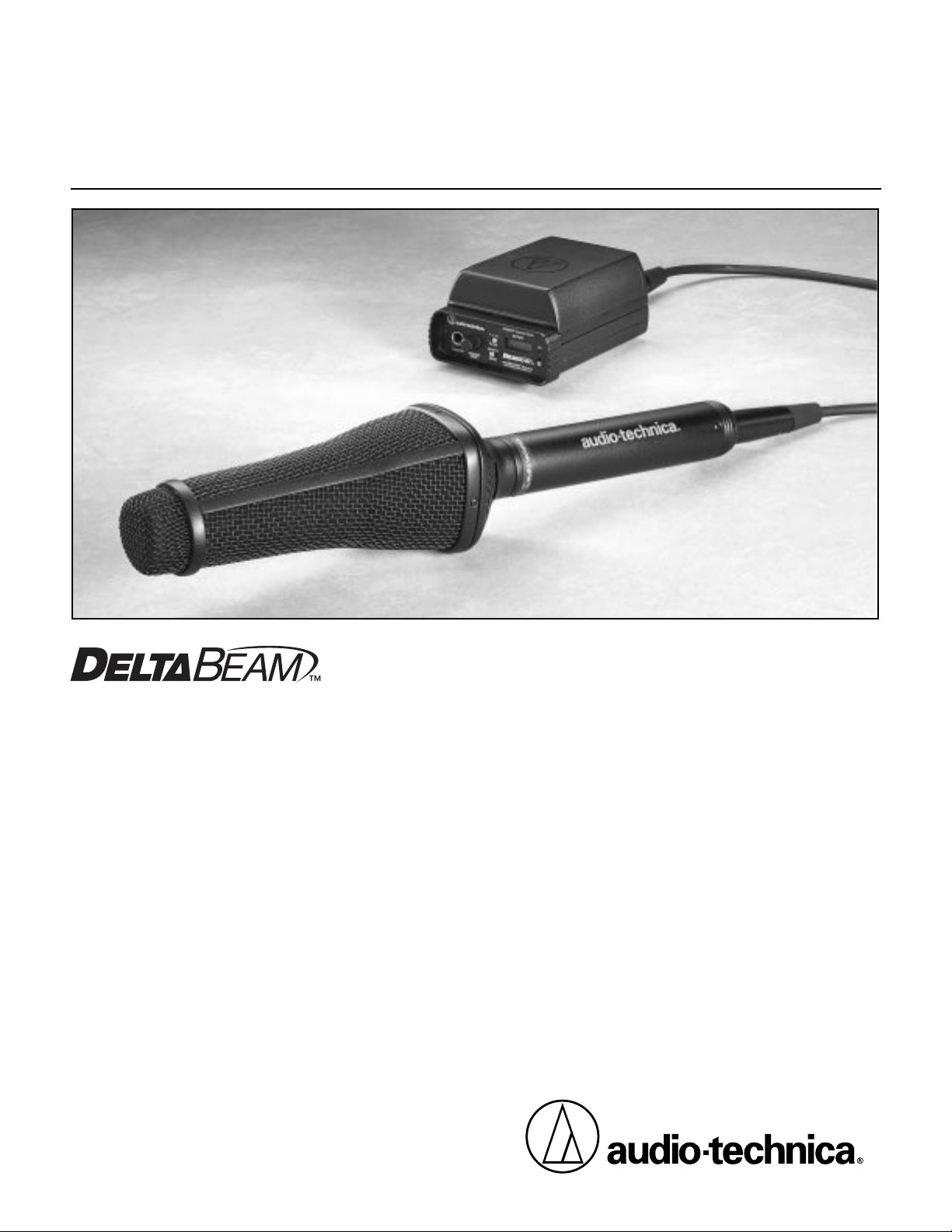
Adaptive-array Microphone Systems
AT895
AT895/MK
Mount Kit
AT895/RK
Remote Kit
Installation and Operation
Page 2

2
AT895 Adaptive-array Microphone Systems
Installation and Operation
Note: This equipment has been tested and found to
comply with the limits for a Class B digital device,
pursuant to Part 15 of the FCC rules. These limits are
designed to provide reasonable protection against harmful
interference in a residential installation. This equipment
generates, uses, and can radiate radio frequency energy
and, if not installed and used in accordance with the
instructions, may cause harmful interference to radio
communications. However, there is no guarantee that
interference will not occur in a particular installation. If
this equipment does cause harmful interference to radio
or television reception, which can be determined by
turning the equipment off and on, the user is encouraged
to try to correct the interference by one or more of the
following measures:
• Reorient or relocate the receiving antenna.
• Increase the separation between the equipment and
the receiver.
• Connect the equipment into an outlet on a circuit
different from that to which the receiver is connected.
• Consult the dealer or an experienced radio TV
technician for help.
Incorporated in the AT895 design are: DSDA-PRO™software (U.S. Patent No. 5,825,898) by Lamar Signal Processing, Ltd., a wholly-owned
subsidiary of Andrea Electronics Corporation; DeltaBeam™(U.S. Patent pending) and MicroLine®technologies by Audio-Technica.
“DSDA-PRO” is a trademark of Lamar Signal Processing, Ltd.; “DeltaBeam” is a trademark of and “MicroLine” is a registered trademark
of Audio-Technica.
Introduction
Thank you for choosing an AT895 Adaptive-array Microphone
System. AT895 Systems incorporate a revolutionary DSPcontrolled five-element microphone array that provides
adaptive directional audio acquisition.
Utilizing Audio-Technica’s proprietary DeltaBeam
™
technology,
the AT895 System manipulates and filters the output of the
array by acoustical, analog and digital means. This process
enhances the pickup of a sound source from a desired
direction relative to unwanted background noise or
interference, providing cancellation of up to 80 dB. Other
benefits include minimized audibility of proximity effect,
minimized nearfield effect on the low-frequency directionality
of the array, and markedly reduced susceptibility to
mechanical noise, wind noise and racking as compared to
currently-available professional microphones.
The AT895 functions equally well for handheld interview use
or long-range sound pickup – in the field, in the studio, or in
security operations.
Warning: Changes or modifications to this unit
not expressly approved by the party responsible for
compliance could void the user’s authority to operate
the equipment.
Compare acceptance angles (at 3 dB down):
Microphone 200 Hz 400 Hz 1 kHz 2 kHz 4 kHz 8 kHz
Shotgun 60˚ 60˚ 60˚ 50˚ 30˚ 20˚
AT895 20˚ 20˚ 20˚ 20˚ 60˚ 50˚
Compare polar patterns at 200 Hz:
Microphone 200 Hz Rejection at 90˚/270˚
Shotgun 15 dB
AT895 70 dB
Compare maximum off-axis rejection:
Microphone Maximum Off-axis Rejection
Shotgun 30 dB
AT895 80 dB
AT895 vs. Typical Shotgun Performance
†
†
Compared to typical performance of a professional-quality 15.5" line + gradient microphone (measurement conditions: 1Pa
at 0.5 m). Due to the adaptive nature of its digital processing, AT895 performance in actual field conditions will vary with the
environment encountered.
Page 3
Control features on the AT895CP are:
• Three-position Mode (pickup pattern) switch which provides
Full-field Adaptive ( ) Planar-adaptive ( ) and
Line + Gradient ( ) settings. (See page 5 for a full
explanation of the Mode settings).
• Audio filter switch with Flat, High-pass and Band-pass
settings.
• Monitor headphone jack with volume control.
• LCD battery condition indicator.
• Power switch with LED indicator.
The Basic System
AT895 Microphone
The AT895 Microphone itself is “all analog,” housing one
Audio-Technica MicroLine
®
element, four A-T cardioid
elements mounted in a co-planar diamond configuration, and
five mic preamps. The five amplified analog signals from the
microphone elements are sent individually down a special
detachable cable to the AT895CP Control Pack.
AT895CP Control Pack
The AT895CP Control Pack provides all the power, Digital
Signal Processing, and control for the AT895. Output from
the Control Pack is analog at mic-level (–23 dBV).
The lightweight, sturdy metal housing accepts a quick-change,
click-on Battery Housing for totally self-contained operation, if
desired. The Control Pack also operates on external 12-14V
DC — from an Anton/Bauer or similar-type battery source, or
from an AC adapter — via an industry-standard 4-pin XLR-type
connection.
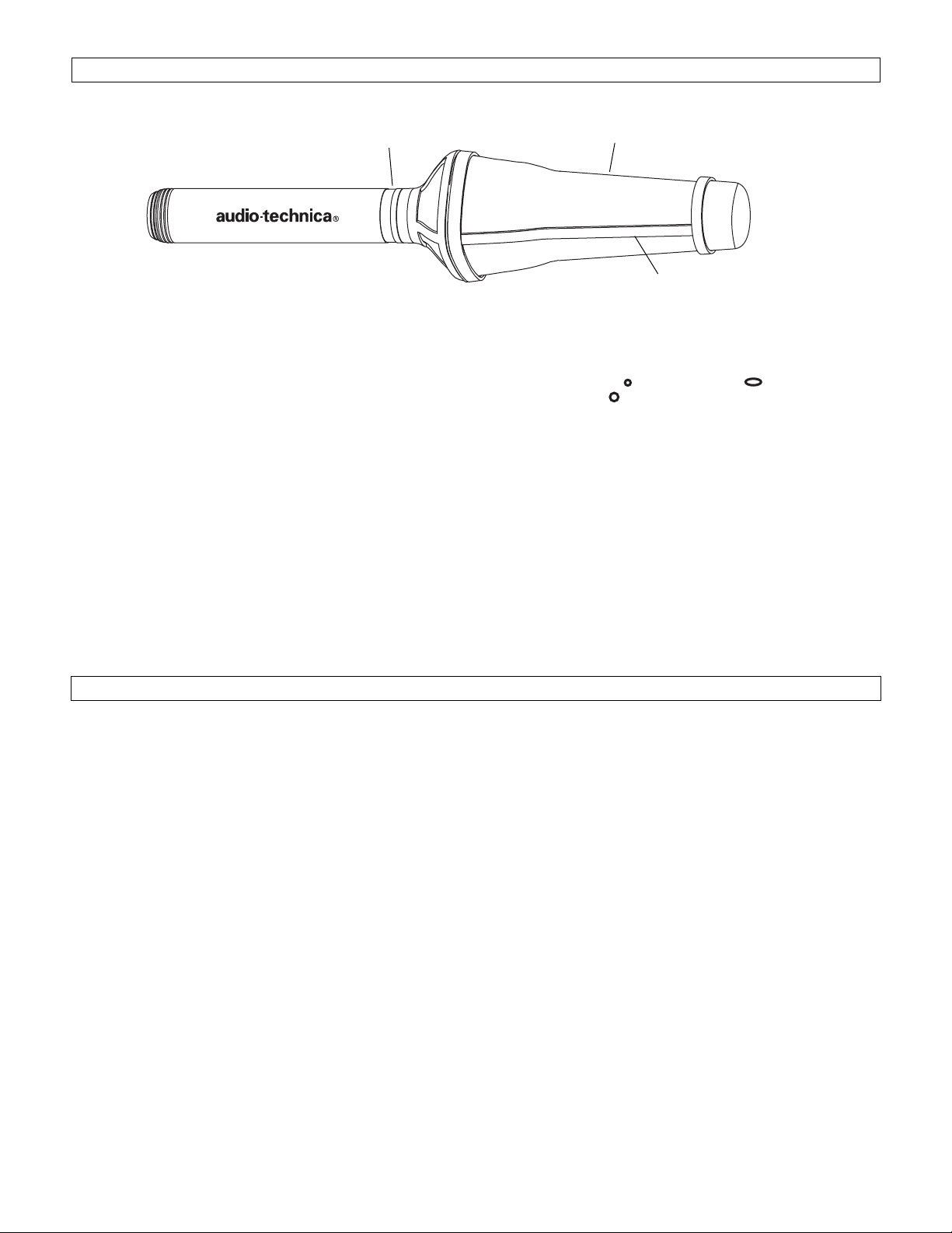
3
No ribs
on “Top”
and “Bottom”
Ribs
on “Sides”
Model No.
“AT895”
at “Top”
Two System Configurations
The AT895 is available as the AT895/RK “Remote Kit” for
field use, and as the AT895/MK “Mount Kit” for studio and
fixed-install applications.
AT895/RK Remote Kit includes:
• AT895MIC Adaptive-array Microphone
• AT895CP Control Pack with attached belt clip
• AT895BH Click-on Battery Housing
• AT895PG Pistol-grip shock mount
• AT895Z Zeppelin-type windscreen
• AT895C-10 Special 6-conductor shielded Cable, 10' long
• AT895CC Carrying Case
AT895/MK Mount Kit includes:
• AT895MIC Adaptive-array Microphone
• AT895CP Control Pack
• AT895SC Shock-mount Stand Clamp with
5
/8"-27
threaded stud
• AT895PS1 Multi-input AC Power Supply with “120V” IEC
detachable power cord
• AT895C-25 Special 6-conductor shielded Cable, 25' long
All components and accessories are interchangeable and
available separately to augment systems or to use as “field
spares.” In addition, two accessory kits are available:
• AT895CK Conversion Kit adds the components needed
for an AT895/MK system to function as an
AT895/RK system.
• AT895FBK Fisher Boom Kit permits use of the AT895 on
a Fisher boom.
(See page 7 for a complete listing of available system
components and accessories.)
The AT895 Microphone and Control Pack are designed to
operate as a system only. Do not attempt to use these
components with other devices.
Fig. A AT895 Microphone
Page 4

Front Panel Controls and Functions (Fig. B)
1. MONITOR:
1
/4" (6.3 mm) Monitor headphone jack; TRS
type with signal on both Tip and Ring.
2. MONITOR LEVEL: Monitor headphone level control.
3. FILTER SWITCH: 3-position switch offers Flat ( ) ,
High-pass ( ) and Band-pass ( ) settings.
4. MODE (PICKUP PATTERN) SWITCH: 3-position switch
offers Full-field Adaptive ( ) , Planar-adaptive ( ) and
Line + Gradient ( ) settings. (See page 5 for a full
explanation of the Mode settings.)
5. LCD BATTERY CONDITION INDICATOR: Markers disappear
as power remaining decreases. Functions only during 9V
battery operation using the AT895BH.
6. POWER LED INDICATOR: Lights red when power is on.
7. POWER SWITCH: On/off switch controls DC power from
all sources.
4
AT895CP Controls and Functions
Rear Panel Functions (Fig. C)
8. BALANCED AUDIO OUTPUT JACK: 3-pin XLRM-type
connector. Output is analog; the balanced signal appears
across Pins 2 and 3. Output phase is “Pin 2 hot;” positive
acoustic pressure produces positive voltage at Pin 2. Pin
1 is ground (shield). A standard 2-conductor shielded
cable (not included) can be used to connect the AT895CP
output to the associated electronics. Phantom power
cannot be used, but if present will have no effect on the
Control Pack.
9. DC POWER INPUT: 4-pin XLRM-type connector for an
external 12-14V DC source from an Anton/Bauer or
similar battery supply, or from an AC adapter. Wiring
is industry-standard: V– on Pin 1, V+ on Pin 4, no
connection to Pins 2 or 3.
10. MIC INPUT JACK: 7-pin XLRM-type connector accepts
the special AT895C 6-conductor shielded cable used to
connect the AT895 Microphone to the Control Pack.
Fig. B Control Pack Front Panel
Fig. C Control Pack Rear Panel
1
2
7
8
9
10
3
5
6
4
Page 5

The microphone array in the AT895 consists of one
Audio-Technica MicroLine
®
element and four A-T cardioid
elements mounted in a co-planar diamond configuration.
A switch on the AT895CP Control Pack selects from three
Mode (pickup pattern) options: two “adaptive” modes and
one “non-adaptive” mode.
In the adaptive modes, signals from the MicroLine
®
element
and either one pair (labeled 1 & 2 in Fig. D) or both pairs
(1 & 2, 3 & 4) of the “corrective” cardioid elements are
utilized. These signals are processed in the Control Pack by
both analog and digital means to provide continuouslyadapting rejection of off-axis sounds. This means that as
the off-axis soundscape changes (either in intensity or
directionality) the microphone system compensates for those
changes. Even off-axis wind is interpreted as unwanted noise,
and is suppressed.
Full-field adaptive Mode ( )
The Full-field adaptive mode provides the maximum
directionality and off-axis rejection. Signals from the
MicroLine
®
element and both pairs of cardioid elements are
utilized.
Planar-adaptive Mode ( )
In the Planar-adaptive mode, signals from the MicroLine
®
element and only the “vertical” pair of cardioid elements
(1 & 2) are utilized. The resultant “elliptical” pickup pattern
provides optimum rejection in one plane (tighter vertically,
wider horizontally).
Mode (Pickup Pattern) Settings
Understanding the correct orientation of the microphone is
crucial for effective application of the Planar-adaptive mode.
When the microphone is positioned with the Audio-Technica
logos along the
sides
of the mic handle and the “AT895” on
the name ring is “up” (as shown above and in Fig. A on page
3), maximum off-axis rejection occurs in the vertical plane of
the pickup pattern only, while the horizontal pickup is nonadaptive. This produces a “horizontal ellipse” pickup pattern.
(Of course, if the microphone is rotated 90 degrees, so the
logos are at the “top” and “bottom” of the handle and the
AT895 name ring marking is “sideways,” the resulting pattern
would be “tall” and adaptively “narrow.”)
Line + Gradient Mode ( )
The Line + Gradient mode is non-adaptive, with only the
signal from the MicroLine
®
element being utilized. (The
cardioid elements and the adaptive circuitry are still
functioning, but the “correcting” signals are not applied
to the MicroLine
®
element’s signal.)
5
Fig. D AT895 Microphone Elements
Model No.
“AT895”
at “Top”
MicroLine
®
1
4
3
2
Page 6

Power Sources
AT895Z Zeppelin-Type Windscreen
AT895PG Pistol-Grip Shock Mount
AT895BH Battery Housing
6
Battery Selection and Installation
Always use fresh alkaline or lithium 9V batteries. For greatest
reliability and longest operation, replace all three batteries at
the same time, using identical types.
To open the battery tray, press down firmly on the tray
release button until it clicks; then
lift the tray slightly
and slide
it out. Insert three batteries, observing polarity as marked
inside the battery compartment. Slide the battery tray closed,
making certain it clicks shut. Due to current requirements of
the system, always use three batteries.
Attaching the Battery Housing to the Control Pack
Slide the Battery Housing onto the Control Pack. When it is
fully seated, the two release buttons at the bottom of the
Battery Housing will click into place.
To remove the Battery Housing, simultaneously push both
release buttons while sliding it down and off the Control Pack.
The Battery Housing may be in place when external power
is used. The batteries will still be consumed, but at a slower
rate, depending upon the external voltage. The batteries will
also provide “back-up power” in case of external supply
interruption.
The two sections of the AT895Z Zeppelin-type windscreen
bayonet-latch together. To open the windscreen, rotate the
rear section to the left (counter-clockwise, viewed from the
rear), then pull the sections apart. Place the “nose” of the
microphone in the foam recess provided in the front section.
Slide the rear section of the windscreen over the handle of
the mic until it reaches the front section,
making certain the
mic’s “nose” remains in its foam recess.
Engage the bayonet
lugs on the windscreen and rotate the rear section fully to
the right (clockwise). Once installed, the windscreen may
be rotated on the microphone if desired.
The AT895CP Control Pack may be powered three different
ways:
• From an AC adapter, using an industry-standard 4-pin XLR
connection. (An AC power supply with 9V DC output is
included in the AT895/MK System).
• From an Anton/Bauer or similar-type external 12-14V battery
source.
• From three 9V batteries in a click-on AT895BH Battery
Housing (included in the AT895/RK System) for completely
self-contained operation.
For correct balance of the microphone and proper orientation
of the elements, the microphone should be mounted in the
AT895PG with the Audio -Technica logos visible between the
rubber rings along the left and right sides. In use, the rubber
rings should be positioned
behind
the Pistol-grip, above the
user’s forearm. (If the Zeppelin is to be used, the mic must
be installed in it before mounting the mic in the Pistol-grip.)
Page 7

7
Specifications
†
System Components and Accessories
Elements (5) Fixed-charge back plate
permanently polarized condenser
Pickup Pattern Modes Full-field adaptive,
Planar-adaptive, Line + Gradient
Frequency Response 60-12,000 Hz
High-pass Filter 80 Hz, 18 dB/octave
(Low-end Roll-off)
Band-pass Filter 300-5,500 Hz, 6 dB/octave
Open Circuit Sensitivity –23 dBV (70 mV) at 1 Pa*, 1kHz
Output Impedance 450 ohms
Maximum Input Sound Level 117 dB SPL, 1 kHz at 1% T.H.D.
Noise, Typical (A-weighted) 24 dB
Dynamic Range (Typical) 93 dB, 1 kHz at Max SPL
Signal-To-Noise Ratio
1
70 dB, 1 kHz at 1 Pa*
Monitor Headphone Output 120 mW max. at 1 kHz, 1%
T.H.D., (Typical) into 20 ohm (each channel)
stereo headphones
Monitor Headphone Jack
1
/4" TRS, signal on both
Tip and Ring
External Power Requirement 9-15V DC, 250 mA typical
Battery Requirement Three 9V (NEDA type 1604),
(AT895BH) not included
Battery Life, Typical Alkaline: 4-6 hours
(AT895BH) Lithium: 10-12 hours
Weight
AT895 Microphone 16.7 oz (473 g)
(less cable)
AT895CP Control Pack 10.0 oz (284 g)
AT895BH Battery Holder 7.6 oz (215 g)
(with typical batteries)
AT895PG Pistol Grip 10.0 oz (284 g)
AT895Z Zeppelin 5.0 oz (142 g)
Windscreen
Dimensions
AT895 Microphone 14.00" (355.6 mm) long,
2.75" (69.9 mm) max. diameter,
1.18" (30.0 mm) handle diameter
AT895CP Control Pack 4.16" (105.7 mm) long,
3.34" (84.8 mm) wide,
0.98" (24.9 mm) high
AT895BH Battery Holder 4.13" (104.9 mm) long,
3.28" (83.3 mm) wide,
1.27" (32.3 mm) high
Output Connector Integral 3-pin XLRM-type
(Control Pack)
Cable 6-conductor shielded cable with
XLR7F-type connectors
AT895/RK 10' (3.0 m) long
AT895/MK 25' (7.6 m) long
† In the interest of standards development, A.T.U.S. offers full details on
its test methods to other industry professionals on request.
* 1 Pascal = 10 dynes/cm
2
= 10 microbars = 94 dB SPL
1
Typical, A-weighted, using Audio Precision System One.
All AT895 components and accessories are interchangeable
and available separately to augment systems or to be used as
“field spares.”
Basic System Components
AT895MIC Adaptive-array Microphone
AT895CP Control Pack with attached belt clip.
AT895 Microphone Accessories
AT895PG Pistol-grip shock mount. (
3
/8"-16 threaded
metal insert in bottom of grip.)
AT895SC Shock-mount Stand Clamp with
5
/8"-27
threaded stud for mounting the AT895 on a
microphone stand.
AT895Z Zeppelin-type windscreen reduces on-axis
wind noise while protecting the microphone.
AT895CP Control Pack Accessories
AT895BH Click-on Battery Housing holds three 9V bat-
teries for self-contained AT895 operation.
AT895PS1 Switching Power Supply (90-263V AC input,
47-63 Hz), UL/CSA/TÜV-approved, with
detachable “120V” 3-pin IEC power cord.
Output 9V DC regulated, 1.5A max. Attached
output cable is 6'/1.8 m long, terminating in an
XLR4F-type connector.
AT895RP Rack-mount plate for mounting one or two
AT895CP Control Packs in a 1U 19" rack
space.
Cables
AT895C-xx Special 6-conductor shielded cable with
XLR7F-XLR7F connectors for use between the
AT895 Microphone and AT895CP Control
Pack. Available in 1.5'/0.4 m (C-1.5), 10'/ 3 m
(C-10), 25'/ 7.6 m (C-25), 50'/15.2 m (C-50) and
100'/30.4 m (C-100) lengths. Custom lengths
are available on special order from the A-T
Service Department.
Conversion Kit
AT895CK Conversion Kit adds the components needed
for an AT895/MK system to function as an
AT895/RK system. Includes AT895BH Battery
Housing, AT895PG Pistol-grip shock mount,
AT895Z Zeppelin-type windscreen, AT895CC
Carrying Case, AT895C-10 special 10'/ 3 m
cable.
Fisher Boom Kit
AT895FBK Fisher Boom Kit adapts the AT895 for use
with a Fisher boom. Includes mounting bracket adapter and special 30'/9.1 m cloth-covered
cable.
Carrying Case
AT895CC All-weather, protective carrying case with
pressure equalization vent, custom-fitted to
hold all AT895/RK System components.
Page 8

Audio-Technica U.S., Inc., 1221 Commerce Drive, Stow, Ohio 44224 330/686-2600 www.audio-technica.com
Audio-Technica Limited, Old Lane, Leeds LS11 8AG England 0113 277 1441
P51171-B/ W ©1999 Audio-Technica U.S., Inc. Printed in U.S.A.
One-Year Limited Warranty
Audio-Technica brand products purchased in the U.S.A. are warranted for one year from date of purchase by Audio-Technica U.S., Inc. ( A.T.U.S.) to be
free of defects in materials and workmanship. In event of such defect, product will be repaired promptly without charge or, at our option, replaced
with a new product of equal or superior value if delivered to A.T.U.S. or an Authorized Service Center, prepaid, together with the sales slip or other
proof of purchase date.
Prior approval from A.T.U.S. is required for return.
This warranty excludes defects due to normal wear, abuse, shipping
damage, or failure to use product in accordance with instructions. This warranty is void in the event of unauthorized repair or modification, or removal
or defacing of the product labeling.
For return approval and shipping information,
contact the Service Dept., Audio-Technica U.S., Inc., 1221 Commerce Drive, Stow, Ohio 44224.
Except to the extent precluded by applicable state law,
A.T.U.S. will have no liability for any consequential, incidental, or special damages; any
warranty of merchantability or fitness for particular purpose expires when this warranty expires.
This warranty gives you specific legal rights, and you may have other rights which vary from state to state.
Outside the U.S.A., please contact your local dealer for warranty details.
 Loading...