

Page 1
Hardware Installation Manual
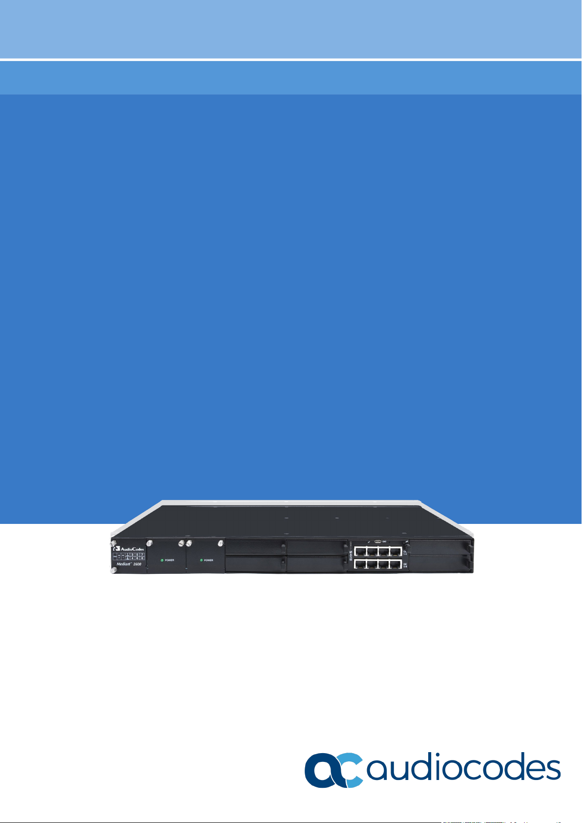
AudioCodes Family of Mediant™ Session Border Controllers (SBC)
Mediant 2600 SBC
Page 2

Page 3

Hardware Installation Manual Contents
Table of Contents
1 Introduction ......................................................................................................... 9
2 Unpacking the Device ....................................................................................... 11
3 Physical Description ......................................................................................... 13
3.1 Physical Dimensions ............................................................................................ 13
3.2 Front Panel Description ........................................................................................ 13
3.2.1 Fan Tray Module ......................................................................................................14
3.2.2 Power Supply Modules ............................................................................................14
3.2.2.1 Power LED Description ............................................................................15
3.2.3 E-SBC Module .........................................................................................................15
3.2.3.1 Ports Description ......................................................................................15
3.2.3.2 LEDs Description ......................................................................................16
3.2.4 Media Processing Module .......................................................................................18
3.3 Rear Panel Description ......................................................................................... 19
4 Mounting the Device ......................................................................................... 21
4.1 Desktop Mounting ................................................................................................ 21
4.2 Rack Mounting ..................................................................................................... 22
4.2.1 Mounting in a 19-inch Rack using a Pre-Installed Rack Shelf.................................23
4.2.2 Mounting in a 19-inch Rack using Front and Rear Brackets ...................................23
5 Cabling the Device ............................................................................................ 31
5.1 Grounding the Device ........................................................................................... 31
5.2 Connecting the Ethernet Ports .............................................................................. 32
5.2.1 RJ-45 LAN Connector Pinouts ................................................................................32
5.2.2 Deployment of a Standalone Device .......................................................................33
5.2.3 Deployment of Two Devices for High Availability ....................................................34
5.3 Connecting the Serial Interface to a Computer ..................................................... 35
5.4 Connecting to Power ............................................................................................ 36
6 Hardware Maintenance ..................................................................................... 39
6.1 Prerequisites ........................................................................................................ 39
6.1.1 Grounding the Device ..............................................................................................39
6.1.2 Preventing Electrostatic Discharge Damage ...........................................................39
6.2 Replacing the E-SBC Module ............................................................................... 40
6.3 Installing the MPM ................................................................................................ 41
6.4 Replacing the Fan Tray Module ............................................................................ 42
6.5 Replacing the Power Supply Module .................................................................... 43
Session Border Controllers 3 Mediant 2600 E-SBC
Page 4

Mediant 2600 E-SBC
List of Figures
Figure 3-1: Front Panel .......................................................................................................................... 13
Figure 3-2: E-SBC Module Ports ........................................................................................................... 15
Figure 3-3: E-SBC Module LEDs ........................................................................................................... 16
Figure 3-4: MPM LEDs .......................................................................................................................... 18
Figure 3-5: Rear Panel........................................................................................................................... 19
Figure 4-1: Rubber Feet Locations ........................................................................................................ 21
Figure 4-2: Rear-Mounting Brackets Attached to Rear-Rack Posts (60 cm)......................................... 25
Figure 4-3: Rear-Mounting Brackets Attached to Rear-Rack Posts (> 70 cm) ..................................... 25
Figure 4-4: Attaching Rear-Mounting Flange to Chassis' Rear-Side Mounting Holes (60 cm) ............. 26
Figure 4-5: Attaching Rear-Mounting Flange to Chassis' Rear-Side Mounting Holes (> 70 cm) .......... 26
Figure 4-6: Sliding Rear-Mounting Flanges into the Rear-Mounting Brackets (60 cm) ......................... 27
Figure 4-7: Sliding Rear-Mounting Flanges into the Rear-Mounting Brackets (> 70 cm) ...................... 27
Figure 4-8: Fastening Rear-Mounting Flange to Rear-Mounting Bracket (60 cm) ................................ 28
Figure 4-9: Fastening Rear-Mounting Flange to Rear-Mounting Bracket (> 70 cm) ............................. 28
Figure 4-10: Front-Mounting Brackets Flush and Aligned with Front-Rack Posts (60 cm) ................... 29
Figure 4-11: Front-Mounting Brackets Flush and Aligned with Front-Rack Posts (> 70 cm) ................ 29
Figure 5-1: Grounding the Device .......................................................................................................... 31
Figure 5-2: Connecting the LAN Interface ............................................................................................. 32
Figure 5-3: Ethernet Port Pairs .............................................................................................................. 33
Figure 5-4: Cabling for 1+1 Ethernet-Port Redundancy (Example)....................................................... 33
Figure 5-5: Cabling for High Availability (Example) ............................................................................... 34
Figure 5-6: Serial Interface Cable Adapter and Connector Pinouts ...................................................... 35
Figure 5-7: Connecting the Serial Interface ........................................................................................... 35
Figure 5-8: Connecting to Power ........................................................................................................... 37
Figure 6-1: Connecting ESD Wrist Strap to Chassis ESD Lug.............................................................. 40
Figure 6-2: Module Handle Partially Pulled Out (Top View) .................................................................. 40
Figure 6-3: Module Handle Pushed In (Top View) ................................................................................ 41
Figure 6-4: Extracted Blank AMC Module (Top View) ........................................................................... 41
Figure 6-5: Slot Assignment for MPM (and E-SBC Module) ................................................................. 41
List of Tables
Table 3-1: Physical Dimensions ............................................................................................................ 13
Table 3-2: Front-Panel Description ........................................................................................................ 13
Table 3-3: Power Supply Module LED Description ............................................................................... 15
Table 3-4: E-SBC Module Ports Description ......................................................................................... 16
Table 3-5: E-SBC Module LEDs Description ......................................................................................... 16
Table 3-6: MPM LEDs Description ........................................................................................................ 18
Table 3-7: Rear-Panel Description ........................................................................................................ 19
Table 5-1: RJ-45 Connector Pinouts ..................................................................................................... 32
Table 5-2: Power Specifications ............................................................................................................ 36
Hardware Installation Manual 4 Document #: LTRT-42122
Page 5

Hardware Installation Manual Notices
Notice
Information contained in this document is believed to be accurate and reliable at the time of
printing. However, due to ongoing product improvements and revisions, AudioCodes cannot
guarantee accuracy of printed material after the Date Published nor can it accept responsibility
for errors or omissions. Updates to this document can be downloaded from
https://www.audiocodes.com/library/technical-documents.
This document is subject to change without notice.
Date Published: July-01-2020
WEEE EU Directive
Pursuant to the WEEE EU Directive, electronic and electrical waste must not be disposed
of with unsorted waste. Please contact your local recycling authority for disposal of this
product.
Customer Support
Customer technical support and services are provided by AudioCodes or by an authorized
AudioCodes Service Partner. For more information on how to buy technical support for
AudioCodes products and for contact information, please visit our Website at
https://www.audiocodes.com/services-support/maintenance-and-support.
Abbreviations and Terminology
Each abbreviation, unless widely used, is spelled out in full when first used.
Throughout this manual and unless otherwise specified, the term device refers to the
Mediant 2600 E-SBC.
Session Border Controllers 5 Mediant 2600 E-SBC
Page 6
Mediant 2600 E-SBC
uniquement en intérieur et ne doit pas sortir du bâtiment.
intempéries de température ambiante maximale de 40°C.
l’appareil étant branché à une prise mise à la masse.
approuvés par AudioCodes.
type et du même fabricant.
Related Documentation
SIP Release Notes
Mediant 2600 E-SBC User's Manual
Notes and Warnings
Warning: The device is an INDOOR unit and thus, must be installed ONLY indoors. In
addition, Ethernet port interface cabling must be routed only indoors and must not exit
the building.
Avertissement: L’appareil est une unité d’INTERIEUR et doit donc obligatoirement être
installé en intérieur. En outre, le câblage de l’interface du port Ethernet doit être acheminé
Warning: Installation of this device must be in a weather protected location of maximum
ambient temperature of 40°C.
Manual Name
Avertissement: L’installation de cet appareil doit avoir lieu dans un local protégé des
Warning: Installation and service of this device must be made only by qualified service
personnel in restricted access locations and connected to an earthed power socket.
Avertissement: L’entretien de maintenance de cet appareil doit être effectué
uniquement par un personnel de service qualifié dans des locaux à accès limité et
Caution Electrical Shock
Do not attempt to open or disassemble this device. The device carries high voltage.
Contact with internal components may cause electrical shock and bodily harm.
Ne tentez pas d’ouvrir ni de démonter l’appareil. L’appareil transporte une haute
tension et son contact avec des composants internes risque de vous exposer à
l’électrocution et à des lésions corporelles
Warning: This device is intended to accommodate only AMC modules approved by
AudioCodes.
Avertissement: Cet appareil est destiné à recevoir uniquement des modules AMC
Attention életrocution
Warning: Modules may contain a non-rechargeable lithium battery. If you need to
replace the battery, replace it only with batteries of the same type and manufacturer.
Avertissement: Les modules peuvent contenir une batterie lithium non-rechargeable. Si
vous devez remplacer la batterie, remplacez-la uniquement par des batteries du même
Hardware Installation Manual 6 Document #: LTRT-42122
Page 7

Hardware Installation Manual Notices
Document Revision Record
LTRT Description
41576 Initial versions.
41577 AC power cable warning (Japanese).
41578 Logo updated.
41579 19-inch rack mounting brackets updated.
42120 Fan tray and Power Supply modules replacement updated.
42121 Duration of press for reset to default; trademarks.
42122 Min. operating temp.
Session Border Controllers 7 Mediant 2600 E-SBC
Page 8

Mediant 2600 E-SBC
Documentation Feedback
AudioCodes continually strives to produce high quality documentation. If you have any
comments (suggestions or errors) regarding this document, please fill out the
Documentation Feedback form on our Website at
https://online.audiocodes.com/documentation-feedback.
Hardware Installation Manual 8 Document #: LTRT-42122
Page 9

Hardware Installation Manual 1. Introduction
1 Introduction
This document provides a hardware description of the Mediant 2600 (hereafter referred to
as device) and step-by-step procedures for cabling the device.
Note: For configuring the device, refer to the device's User’s Manual.
Session Border Controllers 9 Mediant 2600 E-SBC
Page 10

Mediant 2600 E-SBC
This page is intentionally left blank.
Hardware Installation Manual 10 Document #: LTRT-42122
Page 11

Hardware Installation Manual 2. Unpacking the Device
2 Unpacking the Device
Follow the procedure below for unpacking the carton in which the device is shipped.
To unpack the device:
1. Open the carton and remove the packing materials.
2. Remove the chassis from the carton.
3. Check that there is no equipment damage.
4. Ensure that in addition to the chassis, the package contains the following items:
• Two AC power cables.
• Four anti-slide bumpers for desktop installation.
• Two-meter serial interface cable adaptor.
5. Check, retain and process any documents.
If there are any damaged or missing items, notify your AudioCodes sales representative.
Session Border Controllers 11 Mediant 2600 E-SBC
Page 12

Mediant 2600 E-SBC
This page is intentionally left blank.
Hardware Installation Manual 12 Document #: LTRT-42122
Page 13
Hardware Installation Manual 3. Physical Description
3 Physical Description
This chapter provides a physical description of the device.
3.1 Physical Dimensions
The device's physical dimensions are listed in the table below.
Table 3-1: Physical Dimensions
Item Description
Enclosure 4/8-slot, 1U chassis
Dimensions (H x W x D) 1U x 19” (444 mm) x 14” (355 mm)
Weight Approx. 11.7 lbs. (5.3 kg)
Environmental
Operational: 5 to 40°C (41 to 104°F)
Storage: -20 to 70°C (-4 to 158°F)
Relative Humidity: 10 to 85% non-condensing
3.2 Front Panel Description
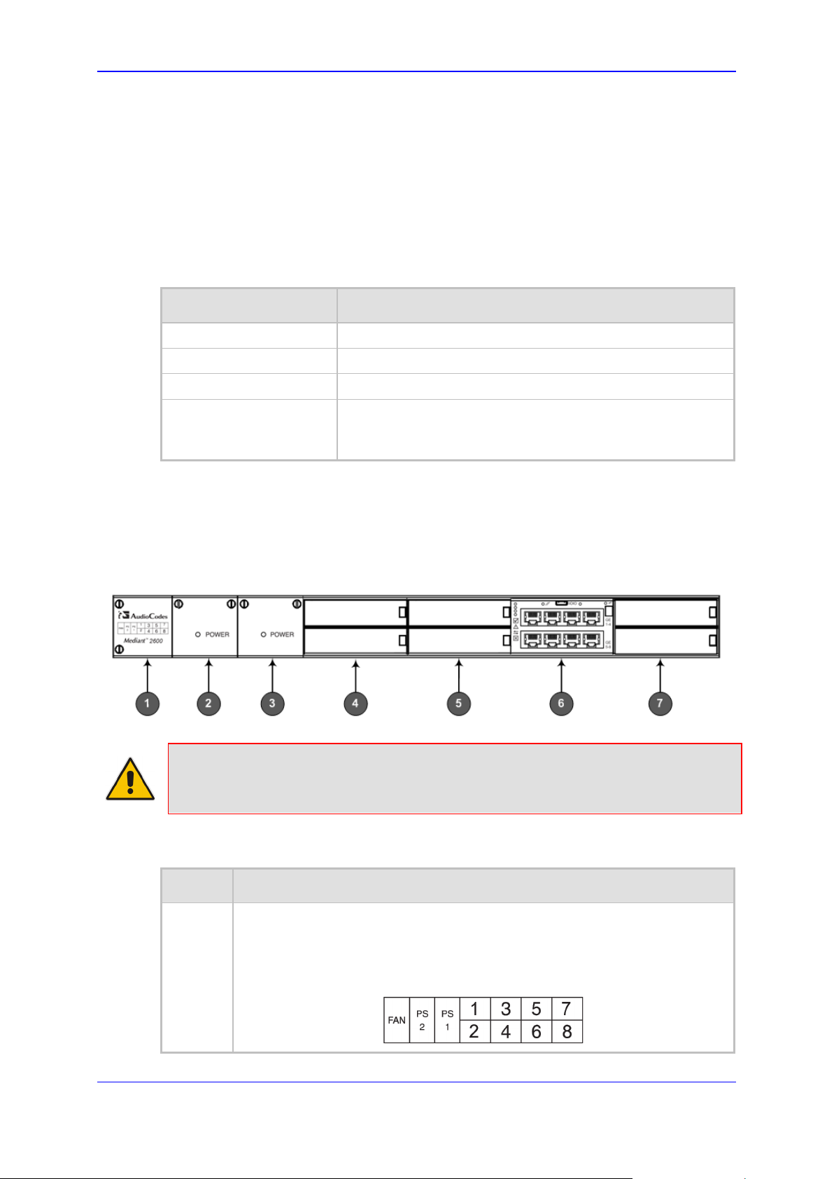
The device's front panel is shown in the figure below and described in the subsequent
table.
Figure 3-1: Front Panel
Note: The figure above provides only an example of the Mediant 2600 hardware
configuration; module slot locations and type of modules (e.g., Media Processing
Module) depend on the ordered hardware configuration.
Table 3-2: Front-Panel Description
Item # Component Description
1 Fan Tray module with a schematic displayed on its front panel showing the
chassis' slot numbers. For more information on this module, see Section 3.2.1
on page 14.
The figure below shows the location of the Fan Tray module, Power Supply
modules, and chassis slot numbers:
Session Border Controllers 13 Mediant 2600 E-SBC
Page 14

Mediant 2600 E-SBC
Item # Component Description
2 Power Supply module No. 2. For more information, see Section 3.2.2 on page
14.
3 Power Supply module No. 1. For more information, see Section 3.2.2 on page
14.
4 Slots 1-2, shown covered with blank AMC modules for unused AMC slots.
These slots house the optional, Media Processing Module (MPM).
Note: The MPM is a customer-ordered item.
5 Slots 3-4, covered with blank AMC modules for unused AMC slots.
Notes:
If you purchased this device in an initial release, Slots 3-4 may be
occupied by the E-SBC CPU AMC module (instead of Slots 5-6).
If this slot is occupied by the E-SBC CPU AMC module and you have
subsequently purchased the MPM, you must re-locate the E-SBC module
to Slots 5-6 instead.
6
Slot 5-6 with E-SBC CPU AMC module (hereafter referred to as E-SBC),
providing CPU, serial interface, and Ethernet interface functionalities. For
more information, see Section 3.2.3 on page 15.
Note: If you purchased this device in an initial release, the E-SBC module
may be occupied in Slots 3-4 (instead of Slots 5-6).
7 Slots 7-8, covered with blank covers for unused AMC slots.
Note: These slots are currently reserved for future use.
3.2.1 Fan Tray Module
The Fan Tray module contains four integrated fans which cool the device's internal
components. The Fan Tray module draws in air through a perforated grill on the left side of
the chassis. The incoming air passes through the entire set of modules, cooling each one,
and then exits the device through perforated vents on the right side of the chassis.
The front panel of the module provides a label showing the chassis slot assignments for
the different modules.
3.2.2 Power Supply Modules
The chassis houses up to two (hot-swappable|) Power Supply modules for providing power
load sharing and AC power redundancy in case of failure of one of the Power Supply
modules. Each module provides an AC power inlet on the rear panel of the chassis for
connection to an electrical power outlet.
Hardware Installation Manual 14 Document #: LTRT-42122
Page 15

Hardware Installation Manual 3. Physical Description
3.2.2.1 Power LED Description
Each Power Supply module provides a POWER LED on its front panel which indicates the
status of the power supply, as described in the table below.
Table 3-3: Power Supply Module LED Description
Color State Description
Green On
- Off Failure / disruption in the AC supply, or the power is currently not
3.2.3 E-SBC Module
The E-SBC module provides the main functionalities of the device. These functionalities
include the central processor unit (CPU), Ethernet port interfaces, serial interface, and a
reset pinhole button. The E-SBC module is installed in Slots 5-6 (see note below).
Note: If you purchased your Mediant 2600 in an initial release, your device may have
been shipped with this module housed in Slots 3-4. If this is the case and you have
subsequently purchased the Media Processing module (MPM), you must re-locate the ESBC module to Slots 5-6.
3.2.3.1 Ports Description
The E-SBC module provides various port interfaces as shown in the figure below and
described in the subsequent table.
Power supply is operating correctly.
being supplied to the device through the AC power supply entry.
Figure 3-2: E-SBC Module Ports
Session Border Controllers 15 Mediant 2600 E-SBC
Page 16

Mediant 2600 E-SBC
Table 3-4: E-SBC Module Ports Description
Item # Label Description
1
2 IOIO RS-232 port for serial communication with a computer.
3 - Pinhole button (reserved for future use).
4 - Handle of AMC module for installing and removing the module.
5 - LAN sub-module, providing eight, 1000Base-T (Gigabit) Ethernet ports
Reset pinhole button:
To reset the device, press the button for at least 1 second (but not
more than 10 seconds).
To reset the device to factory defaults, press the button for at least
15 seconds (but not more than 25 seconds).
for connecting to the IP network. The Ethernet ports operate in pairs,
where one port is active and the other standby, providing 1+1 Ethernet
redundancy. These ports support half- and full-duplex modes, autonegotiation, straight-through and crossover cable detection.
3.2.3.2 LEDs Description
The E-SBC module provides LEDs for indicating various operating status, as described in
the table below.
Figure 3-3: E-SBC Module LEDs
Table 3-5: E-SBC Module LEDs Description
Item #
1
- Off Module out of service
2
Green On Normal operation
3
Flashing Application running in High Availability (HA)
Hardware Installation Manual 16 Document #: LTRT-42122
LED Color State Description
Green On Module in service
- Off During booting up state
Red On Booting up phase / fault detected in module
- Off During booting up state
Green On Application running in Standalone state
Page 17

Hardware Installation Manual 3. Physical Description
Active state
Item #
Yellow On Application is starting Boot / synchronizing
Flashing Application is running in HA Redundant state
4
- Off Normal operation
5 Left LED
6 Right LED
7
LED Color State Description
HA
on
Ethernet
Ports
on
Ethernet
Ports
Red On Out of service
Green On Ethernet link established.
Flashing Data is being received or transmitted
(activity) on the Ethernet port.
- Off No Ethernet link.
Orange On 1000Base-T (Gigabit) Ethernet link
established.
- Off
Blue On Blue hot-swap LED indicating that the AMC
No Ethernet link or 100Base-Tx link
established.
module can be fully removed or inserted.
Note: Do not remove the module before this
LED turns blue.
- Off The module insertion process is complete.
Session Border Controllers 17 Mediant 2600 E-SBC
Page 18

Mediant 2600 E-SBC
3.2.4 Media Processing Module
The Media Processing module (MPM) is an optional, customer-ordered module that
provides additional digital signaling resources (DSP) required for transcoding call sessions.
The addition of this module increases the maximum number of sessions that can undergo
transcoding.
The MPM is an AMC-based module that is installed in Slots 1 and 2.
Notes:
• If you are installing the MPM, the device must be powered off during installation. For
more information, see Section 6.3 on page 41.
• The serial port and reset pinhole button are reserved for future use. Please do not
use these items.
The MPM provides LEDs for indicating various operating status, as shown in the figure
below and described in the subsequent table.
Figure 3-4: MPM LEDs
Table 3-6: MPM LEDs Description
Item #
1
- Off Module out of service
Green On Normal operation
3
- Off During booting up state
4
- Off Normal operation
5
LED Color State Description
Green On Module in service
Red On Booting up phase
Green On Application running
Yellow On Application is starting boot up
Red On Out of service
Blue On Blue hot-swap LED indicating that the
module can be fully removed or inserted.
Note: Do not remove the module before this
LED turns blue.
- Off The module insertion process is complete.
Hardware Installation Manual 18 Document #: LTRT-42122
Page 19

Hardware Installation Manual 3. Physical Description
3.3 Rear Panel Description
The chassis rear panel is displayed in the figure below and described in the subsequent
table.
Figure 3-5: Rear Panel
Table 3-7: Rear-Panel Description
Item # Label Description
1 1
2 2
3 ESD Electrostatic Discharge (ESD) socket.
4
AC power supply inlet (100-240V~2.5A, 50-60 Hz) for
Power Supply module No. 1.
AC power supply inlet (100-240V~2.5A, 50-60 Hz) for
Power Supply module No. 2.
Protective earthing screw.
Session Border Controllers 19 Mediant 2600 E-SBC
Page 20

Mediant 2600 E-SBC
This page is intentionally left blank.
Hardware Installation Manual 20 Document #: LTRT-42122
Page 21

Hardware Installation Manual 4. Mounting the Device
pour éviter de bloquer les bouches d’aération.
4 Mounting the Device
The device can be mounted in one of the following ways:
Placed on a desktop (see Section 'Desktop Mounting' on page 21)
Installed in a standard 19-inch rack (see Section ‘Rack Mounting' on page 22)
Warning: The sides of the chassis, where the air vents are located must remain
unobstructed to ensure adequate airflow and prevent overheating inside the chassis.
Pay attention to wiring and cable routes to avoid blocking of the ventilation openings.
Avertissement : Les panneaux latéraux du châssis où se trouvent les buses de
ventilation doivent être dégagés pour assurer un flux d’air adéquat et prévenir la
surchauffe à l’intérieur du châssis. Faites attention au câblage et aux chemins de câbles
4.1 Desktop Mounting
The device can be mounted on a desktop by attaching the four anti-slide bumpers
(supplied) to the underside of the device. Once you have attached these bumpers, simply
place it on a desktop in the desired position.
To attach the anti-slide rubber bumpers to the device:
1. Flip the device over so that its underside faces up.
2. Locate the four anti-slide grooves on the underside -- one on each corner.
Figure 4-1: Rubber Feet Locations
3. Peel off the adhesive, anti-slide rubber feet (supplied) and stick one in each anti-slide
groove.
4. Flip the device over again so that it rests on its underside with the rubber feet in
Session Border Controllers 21 Mediant 2600 E-SBC
contact with the surface.
Page 22

Mediant 2600 E-SBC
direct connections to the branch circuit (e.g., use of power strips.)
4.2 Rack Mounting
The device is designed to fit into a 19-inch industrial rack of 1 rack-unit height (1U). You
can mount it in the rack using any one of the following mounting options:
(Recommended) Mounting the chassis on a pre-installed shelf in a 19-inch rack – see
Section 4.2.1 on page 23
Mounting the chassis by attaching it directly to the 19-inch rack frame (posts) using
both the pre-installed front-mounting brackets and the rear-mounting brackets – see
Section 4.2.2 on page 23
Rack Mount Safety Instructions
When installing the chassis in a rack, implement the following safety instructions:
• Elevated Operating Temperature: If installed in a closed or multi-unit rack
assembly, the operating ambient temperature of the rack environment may be
greater than room ambient temperature. Therefore, consideration should be given to
installing the equipment in an environment compatible with the maximum ambient
temperature (TA) of 40°C (104°F).
• Reduced Air Flow: Installation of the equipment in a rack should be such that the
amount of air flow required for safe operation on the equipment is not compromised.
• Mechanical Loading: Mounting of the equipment in the rack should be such that a
hazardous condition is not achieved due to uneven mechanical loading.
• Circuit Overloading: Consideration should be given to the connection of the
equipment to the supply circuit and the effect that overloading of the circuits might
have on over-current protection and supply wiring. Appropriate consideration of
equipment nameplate ratings should be used when addressing this concern.
• Reliable Earthing: Reliable earthing of rack-mounted equipment should be
maintained. Particular attention should be given to supply connections other than
Hardware Installation Manual 22 Document #: LTRT-42122
Page 23

Hardware Installation Manual 4. Mounting the Device
4.2.1 Mounting in a 19-inch Rack using a Pre-Installed Rack Shelf
The device can be placed on a pre-installed shelf in a 19-inch rack, as described below.
This is the recommended method for mounting the device.
To mount the device on a pre-installed shelf in a 19-inch rack:
1. Make sure that your rack shelf is secured to the rack posts and in a horizontal level
position in the rack.
2. Place the device on the pre-installed shelf in the rack.
3. Position the chassis so that the pre-attached, front-mounting brackets are flush
against the front rack posts and that the holes of the brackets align with the holes on
the posts.
4. Secure the front-mounting brackets to the rack posts using standard 19-inch rack bolts
(not supplied). This step is crucial in that it prevents the chassis from accidently sliding
off the shelf.
4.2.2 Mounting in a 19-inch Rack using Front and Rear Brackets
The device can be mounted in a 19-inch rack by attaching the chassis directly to the rack
frame, using both front- and rear-mounting brackets.
Warnings:
• At least two people are required to mount the device in the 19-inch rack.
• When attaching the chassis to the rack, it is mandatory to connect it using both the
front-mounting brackets and the rear-mounting brackets (supplied).
Avertissements:
• Au moins deux personnes sont nécessaires pour monter l’appareil dans le bâti 19
pouces.
• En fixant le châssis au bâti, il est impératif de le connecter à l’aide de supports de
montage avant et de supports de montage arrière.réglables (fournis).
Session Border Controllers 23 Mediant 2600 E-SBC
Page 24

Mediant 2600 E-SBC
The device is shipped with the following types of rear-mounting kits, each suited for a
specific rack depth:
Adjustable rear-mounting bracket whose length can be adjusted from 59.3 to 62.7 cm
(23.3 to 24.6 in.) to suit the distance between the chassis and the rear post.
Rear-Mounting Bracket x 2
Rear-Mounting Flange x 2
x 2
x 6
Adjustable rear-mounting bracket whose length can be adjusted from 77 to 83 cm
(30.3 to 32.6 in.) to suit the distance between the chassis and the rear post.
Rear-Mounting Bracket x 2
Rear-Mounting Flange x 2
x 6
Adjustable rear-mounting bracket whose length can be adjusted from 71 to 76 cm
(27.7 to 30.2 in.) to suit the distance between the chassis and the rear post.
Rear-Mounting Bracket x 2
x 6
x 6
Rear-Mounting Flange x 2
x 6
Hardware Installation Manual 24 Document #: LTRT-42122
Page 25

Hardware Installation Manual 4. Mounting the Device
To mount the device in a 19-inch rack using front- and rear-mounting brackets:
5. Open the Rear Mounting Bracket kit and remove its contents. Make sure that all the
items are included in the kit (see above).
6. Attach the two rear-mounting brackets to the two-rear rack posts, using two screws
(not supplied) per bracket. Make sure that you attach the brackets at the same height
level in the rack. See the figure below for correct orientation of the brackets when
attaching them to the posts.
Figure 4-2: Rear-Mounting Brackets Attached to Rear-Rack Posts (60 cm)
Figure 4-3: Rear-Mounting Brackets Attached to Rear-Rack Posts (> 70 cm)
Session Border Controllers 25 Mediant 2600 E-SBC
Page 26

Mediant 2600 E-SBC
7. Attach the rear-mounting flanges to the rear sides of the chassis, using three screws
(supplied) per flange.
Figure 4-4: Attaching Rear-Mounting Flange to Chassis' Rear-Side Mounting Holes (60 cm)
Figure 4-5: Attaching Rear-Mounting Flange to Chassis' Rear-Side Mounting Holes (> 70 cm)
8. With two people, lift the chassis into the rack from the front of the rack.
Hardware Installation Manual 26 Document #: LTRT-42122
Page 27

Hardware Installation Manual 4. Mounting the Device
9. Slide the two rear-mounting flanges into the slide rails of the rear-mounting brackets
that you previously attached to the rear posts.
Figure 4-6: Sliding Rear-Mounting Flanges into the Rear-Mounting Brackets (60 cm)
Figure 4-7: Sliding Rear-Mounting Flanges into the Rear-Mounting Brackets (> 70 cm)
Session Border Controllers 27 Mediant 2600 E-SBC
Page 28

Mediant 2600 E-SBC
10. Hold the chassis in position while the second person secures the rear-mounting
flanges to the rear-mounting brackets. Insert the supplied screws (6-32 x 5/16 inch)
from the inside of the rack, through the flange's grid and into the screw hole on the
rear-mounting bracket. Finger-tighten the screws but make sure that the screws are
NOT fully tightened and that the flange can freely move on the slide rails of the rearmounting bracket.
Figure 4-8: Fastening Rear-Mounting Flange to Rear-Mounting Bracket (60 cm)
Figure 4-9: Fastening Rear-Mounting Flange to Rear-Mounting Bracket (> 70 cm)
Hardware Installation Manual 28 Document #: LTRT-42122
Page 29

Hardware Installation Manual 4. Mounting the Device
11. Hold the chassis for support while the second person positions the chassis so that the
front-mounting brackets are flush against the front-rack posts and that the holes of the
front-mounting brackets align with the holes on the front-rack posts.
Figure 4-10: Front-Mounting Brackets Flush and Aligned with Front-Rack Posts (60 cm)
Figure 4-11: Front-Mounting Brackets Flush and Aligned with Front-Rack Posts (> 70 cm)
12. Hold the chassis in position while the second person secures the two front-mounting
brackets to the front posts, by finger-tightening 19-inch rack bolts (not supplied) to the
rack posts.
Session Border Controllers 29 Mediant 2600 E-SBC
Page 30

Mediant 2600 E-SBC
13. Tighten the bolts on the front-mounting brackets.
14. With a Philips screwdriver, tighten the screws securing the rear-mounting flanges to
the rear-mounting brackets.
Notes:
• Make sure that all the mounting brackets are attached at the same level to the
mounting posts so that the chassis is supported in a horizontal position.
• If the depth of the rack exceeds the maximum length of the adjustable rear-mounting
brackets, install an additional side rack post to accommodate the length of the rearmounting bracket.
Hardware Installation Manual 30 Document #: LTRT-42122
Page 31

Hardware Installation Manual 5. Cabling the Device
5 Cabling the Device
This section describes how to cable the device:
Grounding the device – see Section 5.1 on page 31
Connecting to the LAN – see Section 5.2 on page 32
Connecting to a computer for serial communication – see Section 5.3 on page 35
5.1 Grounding the Device
Connecting to power – see Section 5.4 on page 36
The procedure below describes how to ground the device.
Protective Earthing
The equipment is classified as Class I according to EN-60950-1 and UL 60950-1
and must be earthed at all times (using an equipment-earthing conductor).
• Finland: "Laite on liltettava suojamaadoituskoskettimilla varustettuun
pistorasiaan."
• Norway: "Apparatet rna tilkoples jordet stikkontakt."
• Sweden: "Apparaten skall anslutas till jordat uttag."
To ground the device:
1. Connect an electrically earthed strap of 16 AWG wire (minimum) to the chassis'
earthing screw (located on the rear panel), using the supplied washer.
Figure 5-1: Grounding the Device
2. Connect the other end of the strap to a protective earthing. This should be in
accordance with the regulations enforced in the country in which the device is
installed.
Session Border Controllers 31 Mediant 2600 E-SBC
Page 32

Mediant 2600 E-SBC
5.2 Connecting the Ethernet Ports
This section describes the cabling of the LAN interfaces.
5.2.1 RJ-45 LAN Connector Pinouts
The RJ-45 connectors with the following pinouts are used for the LAN interfaces:
Table 5-1: RJ-45 Connector Pinouts
Pin Name Description
1 BI_DA+ Bi-directional pair A+
2 BI_DA- Bi-directional pair A-
3 BI_DB+ Bi-directional pair B+
4 BI_DC+ Bi-directional pair C+
5 BI_DC- Bi-directional pair C-
6 BI_DB- Bi-directional pair B-
7 BI_DD+ Bi-directional pair D+
8 BI_DD- Bi-directional pair D-
To connect to the LAN:
1. Connect one end of a straight-through RJ-45 Ethernet Cat 5, 5e, or 6 cable to the
Ethernet ports on the LAN module.
Figure 5-2: Connecting the LAN Interface
2. Connect the other end of the cable to the LAN network.
Hardware Installation Manual 32 Document #: LTRT-42122
Page 33

Hardware Installation Manual 5. Cabling the Device
5.2.2 Deployment of a Standalone Device
The Ethernet ports on the E-SBC module can operate in pairs called Ethernet Groups to
provide Ethernet port 1+1 redundancy. In each pair, one port serves as the active Ethernet
port while the other as standby. When the active port fails, the device switches to the
standby Ethernet port.
By default, the Ethernet ports are grouped into pairs, as shown below. However, you can
change this port assignment, including assigning only a single port to an Ethernet Group.
For more information, refer to the User's Manual.
Figure 5-3: Ethernet Port Pairs
It is important that the two ports making up a pair are connected to different switches (but
in the same subnet). The figure below illustrates an example of implementing Ethernet-port
redundancy:
Figure 5-4: Cabling for 1+1 Ethernet-Port Redundancy (Example)
Session Border Controllers 33 Mediant 2600 E-SBC
Page 34

Mediant 2600 E-SBC
5.2.3 Deployment of Two Devices for High Availability
The device supports 1+1 high availability, whereby two devices are deployed and
connected to the same broadcast domain/s. In such a setup, the same Ethernet port-pair
redundancy setup is done for each device. For example, if port-pair 5 and 6 are used for
Device "A", then Device "B" must also use port-pair 5 and 6, as shown in the figure below:
Figure 5-5: Cabling for High Availability (Example)
In High Availability, the two devices interconnect through their Maintenance interfaces,
using the same Ethernet Port Group.
Note: For possible connections (including Tx / Rx settings) between the HA devices,
refer to the User's Manual.
Hardware Installation Manual 34 Document #: LTRT-42122
Page 35

Hardware Installation Manual 5. Cabling the Device
5.3 Connecting the Serial Interface to a Computer
The RS-232 interface port is used to access the command line interface (CLI) for serial
communication. The cable adapter shown below is provided for this purpose:
Figure 5-6: Serial Interface Cable Adapter and Connector Pinouts
To connect the serial interface port to a computer:
1. Connect the Micro-USB connector (labeled "P3" in the figure above) to the serial port
(labeled IOIO) located on the E-SBC module.
Figure 5-7: Connecting the Serial Interface
2. On the other end of the cable, connect the DB-9 connector labeled "P1" (red) to the
RS-232 communication port on your computer.
Notes:
• The RS-232 port is not intended for permanent connection.
• The DB-9 connector labeled "P2" is used only for debugging.
Session Border Controllers 35 Mediant 2600 E-SBC
Page 36

Mediant 2600 E-SBC
ご注意
5.4 Connecting to Power
The procedure below describes how to connect the device to the power supply.
Table 5-2: Power Specifications
Item Description
Power Supply Up to two hot swappable, power supply modules for
power load sharing and AC power redundancy in
case of failure of one of the modules.
Input Ratings
Output Ratings 12 VDC / 10 A max.
Connection to Electrical Outlet AC power supply inlet.
Warnings:
• The device must be connected (by service personnel) to a socket-outlet with a
protective earthing connection.
• Use only the AC power cord supplied with the device.
Avertissements:
• L’appareil doit être branché à une prise murale à condition qu’elle soit mise à la
masse.
• Utilisez uniquement le cordon AC fourni avec l’appareil.
本製品に添付の電源ケーブルは、Mediant 2600 E-SBC
に専用設計されているため、汎用性がありません.
本電源ケーブルを他の機器に使用されないよう、ご注意ください.
Single universal power supply 100-240 VAC, 50-60
Hz, 2.5A max.
Notes:
• You can connect both Power Supply modules (1 and 2), for 1+1 power load-sharing
and redundancy. Each module provides an AC power socket on the device's rear
Hardware Installation Manual 36 Document #: LTRT-42122
panel. If both power modules are used, ensure that you connect each one to a
different AC supply socket.
• The two AC power sources must have the same ground potential.
Page 37

Hardware Installation Manual 5. Cabling the Device
To connect the device to the power supply:
1. Connect the AC power cord (supplied) to one of the power sockets located on the rear
panel.
Figure 5-8: Connecting to Power
2. Connect the other end of the power cord to a standard AC electrical outlet (100-
240V~50-60 Hz).
3. For load sharing and power redundancy, repeat steps 1 through 2, but using the
power socket of the second Power Supply module and connecting this to a different
supply circuit.
4. Turn on the power at the power source (if required).
5. Check that the POWER LED on each Power Supply module (front panel) is lit green.
This indicates that the device is receiving power.
Session Border Controllers 37 Mediant 2600 E-SBC
Page 38

Mediant 2600 E-SBC
This page is intentionally left blank.
Hardware Installation Manual 38 Document #: LTRT-42122
Page 39

Hardware Installation Manual 6. Hardware Maintenance
l’appareil étant branché à une prise mise à la masse.
6 Hardware Maintenance
The device is designed as a modular chassis and allows you to order any module as a
Field Replacement Unit (FRU). This section describes the procedures for installing or
replacing modules.
Warning: Maintenance service of this device must be made only by qualified service
personnel in restricted access locations and connected to an earthed power socket.
Avertissement: L’entretien de maintenance de cet appareil doit être effectué
uniquement par un personnel de service qualifié dans des locaux à accès limité et
Note: Make sure that all unoccupied module chassis slots are covered with blank
panels. This allows optimal internal airflow pressure within the chassis.
6.1 Prerequisites
Before performing any maintenance procedures, read this section.
6.1.1 Grounding the Device
Before performing any maintenance procedures, ensure that your device is properly
grounded, as described in Section 5.1 on page 31.
6.1.2 Preventing Electrostatic Discharge Damage
Electrostatic discharge (ESD) due to improper handling of the device's modules and
components can cause irreversible damage to the equipment. Adhere to the following
guidelines for preventing ESD:
When handling modules, always wear a grounded ESD wrist strap or ankle strap at a
grounded work area to prevent ESD. Connect the equipment end of the strap to the
chassis ESD screw (described in the procedure below).
To prevent static electrical damage to the module, do not touch the electrical
components of the module. Instead, hold the module only on the edges where no
electrical components are located.
Ensure that the modules are securely installed in the chassis.
Session Border Controllers 39 Mediant 2600 E-SBC
Page 40

Mediant 2600 E-SBC
passe au bleu stable. Son retrait prématuré risque d’endommager l’appareil.
To attach an ESD wrist strap to the chassis:
1. Attach the ESD wrist strap to your body (typically, the wrist) so that it is in direct
contact with your skin.
2. Attach the other end of the wrist strap (e.g., an alligator clip) to the ESD spring screw
located on the rear panel of the chassis, as shown below.
Figure 6-1: Connecting ESD Wrist Strap to Chassis ESD Lug
6.2 Replacing the E-SBC Module
The AMC-based E-SBC module is hot-swappable and can be replaced without powering
down the device and disrupting other non-related services running on the device.
Warning: Do not remove an AMC module before its hot-swap LED turns solid blue.
Removing it prematurely may cause damage to the device.
Avertissement : Ne retirez pas le module AMC avant que sa DEL remplacée à chaud ne
To replace the E-SBC module:
1. Remove the failed module:
a. Gently pull the module handle until you hear a click sound. The module is now
partially extracted and undergoes a shutdown sequence.
Figure 6-2: Module Handle Partially Pulled Out (Top View)
b. Wait till the Hot Swap Blue LED is lit, which indicates that the shutdown
sequence has completed.
c. Grip and pull the module handle firmly to slide the module out of the slot.
Hardware Installation Manual 40 Document #: LTRT-42122
Page 41

Hardware Installation Manual 6. Hardware Maintenance
2. Install the new module:
a. Remove the new module from its ESD shielding packet in which it was shipped.
b. Carefully insert the module into the slot and slide it along the slot's guide rails
until it makes contact with the card-edge connector located on the backplane.
c. Using only the module handle, press the module into the chassis to engage it
with the chassis backplane.
Figure 6-3: Module Handle Pushed In (Top View)
d. Connect all external interfacing cables to the module, as required.
6.3 Installing the MPM
The procedure below describes how to install the MPM into the chassis.
Warning: Power down the device before installing the MPM.
Avertissement: Mettez l’appareil hors tension avant d’installer le MPM.
To install the MPM:
1. Remove the new MPM from its ESD shielding packet in which it was shipped.
2. Power down the device (i.e., disconnect the power cables).
3. Remove the blank AMC modules from Slot 1 and Slot 2, by gently pulling on the
module's handle.
Figure 6-4: Extracted Blank AMC Module (Top View)
4. Carefully insert the MPM into Slot 1-2 and slide it along the slot's guide rails until it
makes contact with the card-edge connector located on the backplane.
Figure 6-5: Slot Assignment for MPM (and E-SBC Module)
Session Border Controllers 41 Mediant 2600 E-SBC
Page 42

Mediant 2600 E-SBC
5. Push the module handle of the MPM until it clicks firmly in to engage the MPM with the
chassis backplane.
Note: If you purchased this device in an initial release where the E-SBC module is
housed in Slots 3-4, you must relocate this module to Slots 5-6 instead, as shown
below:
Follow the instructions in Section 6.2 for replacing this module.
6. Power up the device.
6.4 Replacing the Fan Tray Module
This section describes how to replace the Fan Tray module.
Warnings:
• Do not operate the device without the Fan Tray module! Before replacing the Fan
Tray module, ensure that you have the replacement Fan Tray module on hand.
• Before removing the Fan Tray module and after the device has been powered off, the
blades may still be rotating at high speeds. Therefore, wait a few seconds to allow the
blades to stop, prior to extracting the module from the chassis.
Avertissements:
• N’opérez pas l’appareil sans module de Caisse de ventilateur ! Avant de remplacer le
module de Caisse de ventilateur, assurez-vous que vous avez le module de
remplacement en main.
• Avant de retirer le module de Caisse de ventilateur et une fois l’appareil mis hors
tension, les lames risquent de continuer à tourner à grande vitesse. Aussi, patientez
quelques secondes pour permettre aux lames de s’arrêter, avant d’extraire le module
du châssis.
To replace the Fan Tray module:
1. Power off the chassis by disconnecting the power cables from all connected Power
Supply modules.
2. Remove the failed module:
a. Using a flathead screwdriver, on the front panel of the module, loosen the two
screws securing the module to the chassis.
b. Grip the two screws and gently slide the module out of the chassis slot.
3. Install the new module:
a. Align the module with the guiding rails located inside the slot.
b. Gently push the module into the slot until it has engaged with the chassis
backplane.
c. Using a flathead screwdriver, tighten the two module's mounting pins. Fasten the
two screws on the top right-hand corner and the bottom right-hand corner of the
front panel of the Fan Tray module.
4. Power on the chassis by re-connecting the power cables to the Power Supply
modules.
Hardware Installation Manual 42 Document #: LTRT-42122
Page 43

Hardware Installation Manual 6. Hardware Maintenance
6.5 Replacing the Power Supply Module
This section describes how to replace a Power Supply module. If you are using both Power
Supply modules and you need to replace only one of them, as they are hot-swappable, you
can keep the functioning Power Supply module connected to power while you replace the
failed Power Supply module.
Warnings: Before extracting a Power Supply module from the chassis, after you have
disconnected the power cord, wait at least three seconds for the capacitors to discharge.
Avertissements: Avant d’extraire un module de Bloc d’alimentation du châssis (après
avoir débranché le cordon électrique), patientez au moins 3 secondes que les capacités
se déchargent.
To replace a Power Supply module:
1. Remove the failed module:
a. Disconnect the power cable from the module and then wait at least three seconds
for its' capacitors to discharge.
b. Using a flathead screwdriver, on the front panel of the module, loosen the two
screws securing the module to the chassis.
c. Grip the two screws and gently slide the module out of the chassis slot.
2. Install the new module:
a. Align the module with the guiding rails located inside the slot.
b. Gently push the module into the slot until it has engaged with the chassis
backplane.
c. Using a flathead screwdriver, tighten the two module's mounting pins. Fasten the
two screws on the top right-hand corner and the bottom right-hand corner of the
front panel of the Fan Tray module.
d. Re-connect the power cable to the module.
Session Border Controllers 43 Mediant 2600 E-SBC
Page 44

International Headquarters
1 Hayarden Street,
Airport City
Lod 7019900, Israel
Tel: +972-3-976-4000
Fax: +972-3-976-4040
AudioCodes Inc.
200 Cottontail Lane,
Suite A101E,
Somerset, NJ 08873
Tel: +1-732-469-0880
Fax: +1-732-469-2298
Contact us
Website: https://www.audiocodes.com/
©2020 AudioCodes Ltd. All rights reserved. AudioCodes, AC, HD VoIP, HD VoIP Sounds Better, IPmedia, Mediant,
MediaPack, What’s Inside Matters, OSN, SmartTAP, User Management Pack, VMAS, VoIPerfect, VoIPerfectHD, Your
Gateway To VoIP, 3GX, VocaNom, AudioCodes One Voice, AudioCodes Meeting Insights, AudioCodes Room
Experience and CloudBond are trademarks or registered trademarks of AudioCodes Limited. All other products or
trademarks are property of their respective owners. Product specifications are subject to change without notice.
:
https://www.audiocodes.com/corporate/offices-worldwide
Document #: LTRT-42122
 Loading...