

Page 1

User's Manual Version 5.2
Document #: LTRT-68806 September 2007
Page 2

Page 3

SIP User's Manual Contents
Table of Contents
1 Overview............................................................................................................15
1.1 SIP Overview .........................................................................................................15
1.2 Mediant 2000 Overview .........................................................................................15
1.3 TP-1610 Overview .................................................................................................17
1.4 TP-260 Overview ...................................................................................................18
2 Physical Description.........................................................................................19
2.1 Mediant 2000 Physical Description........................................................................ 19
2.1.1 Mediant 2000 Chassis .............................................................................................20
2.1.2 Power Supply...........................................................................................................20
2.1.3 Optional CPU Blade.................................................................................................21
2.2 TP-1610 Physical Description................................................................................ 21
2.2.1 TP-1610 Front Panel LEDs .....................................................................................22
2.2.2 TP-1610 Rear Transition Module ............................................................................23
2.3 TP-260 Physical Description .................................................................................. 25
2.3.1 TP-260 LEDs ...........................................................................................................26
2.3.2 TP-260 Ethernet and E1/T1 Ports ...........................................................................27
3 Installation.........................................................................................................29
3.1 Installing the Mediant 2000 ....................................................................................29
3.1.1 Unpacking................................................................................................................29
3.1.2 Package Contents ...................................................................................................30
3.1.3 Mounting the Mediant 2000 .....................................................................................30
3.1.3.1 Mounting Mediant 2000 on a Desktop .................................................... 31
3.1.3.2 Installing Mediant 2000 in a 19-inch Rack .............................................. 31
3.1.4 Cabling the Mediant 2000........................................................................................33
3.1.4.1 Grounding the Mediant 2000................................................................... 35
3.1.4.2 Connecting the E1/T1 Trunk Interfaces .................................................. 35
3.1.4.3 Connecting the Ethernet Interface .......................................................... 36
3.1.4.4 Connecting the RS-232 Port to a PC ...................................................... 37
3.1.4.5 Connecting the Power Supply................................................................. 38
3.2 Installing the TP-1610 ............................................................................................ 40
3.2.1 Unpacking................................................................................................................40
3.2.2 Package Contents ...................................................................................................41
3.2.3 Installing the TP-1610..............................................................................................41
3.2.3.1 Inserting Blades....................................................................................... 41
3.2.3.2 Removing Blades .................................................................................... 42
3.2.4 Cabling the TP-1610................................................................................................42
3.3 Installing the TP-260 .............................................................................................. 43
3.3.1 Unpacking................................................................................................................43
3.3.2 Package Contents ...................................................................................................44
3.3.3 Installing the TP-260................................................................................................44
3.3.4 Cabling the TP-260..................................................................................................44
3.3.4.1 Connecting the E1/T1 Trunk Interfaces .................................................. 45
3.3.4.2 Connecting the Ethernet Interface .......................................................... 46
Version 5.2 3 September 2007
Page 4

Mediant 2000 & TP-1610 & TP-260/UNI
4 Getting Started ..................................................................................................47
4.1 Configuration Concepts..........................................................................................47
4.2 Startup Process......................................................................................................48
4.3 Assigning an IP Address........................................................................................ 50
4.3.1 Assigning an IP Address Using HTTP.....................................................................50
4.3.2 Assigning an IP Address Using BootP ....................................................................51
4.3.3 Assigning an IP Address Using the CLI...................................................................51
4.3.3.1 Accessing the CLI ................................................................................... 52
4.3.3.2 Assigning an IP Address ......................................................................... 53
4.4 Configuring Basic Parameters ...............................................................................54
5 Web-based Management..................................................................................57
5.1 Computer Requirements ........................................................................................ 57
5.2 Protection and Security Mechanisms.....................................................................57
5.2.1 User Accounts .........................................................................................................58
5.2.2 Limiting the Embedded Web Server to Read-Only Mode .......................................59
5.2.3 Disabling the Embedded Web Server .....................................................................59
5.3 Accessing the Embedded Web Server ..................................................................60
5.4 Getting Acquainted with the Web Interface............................................................61
5.4.1 Main Menu Bar ........................................................................................................62
5.4.2 Saving Changes ......................................................................................................62
5.4.3 Entering Phone Numbers in Various Tables ...........................................................62
5.4.4 Searching for Configuration Parameters .................................................................63
5.4.5 Customizing the Web Interface ...............................................................................65
5.4.5.1 Replacing the Main Corporate Logo ....................................................... 65
5.4.5.2 Replacing the Background Image File .................................................... 68
5.4.5.3 Customizing the Product Name .............................................................. 69
5.4.5.4 Creating a Login Welcome Message ...................................................... 70
5.5 Protocol Management ............................................................................................ 71
5.5.1 Protocol Definition Parameters................................................................................71
5.5.1.1 General Parameters ................................................................................ 72
5.5.1.2 Proxy & Registration Parameters............................................................ 86
5.5.1.3 Coders..................................................................................................... 96
5.5.1.4 DTMF & Dialing Parameters ................................................................... 99
5.5.2 Configuring the Advanced Parameters................................................................. 102
5.5.2.1 General Parameters .............................................................................. 103
5.5.2.2 Supplementary Services ....................................................................... 109
5.5.2.3 Stand-Alone Survivability ...................................................................... 111
5.5.3 Configuring the Number Manipulation Tables ...................................................... 113
5.5.3.1 Dialing Plan Notation............................................................................. 116
5.5.3.2 Numbering Plans and Type of Number................................................. 117
5.5.3.3 Mapping NPI/TON to Phone-Context.................................................... 118
5.5.4 Configuring the Routing Tables ............................................................................ 120
5.5.4.1 General Parameters .............................................................................. 120
5.5.4.2 Tel to IP Routing Table.......................................................................... 122
5.5.4.3 IP to Trunk Group Routing .................................................................... 126
5.5.4.4 Internal DNS Table................................................................................ 128
5.5.4.5 Internal SRV Table ................................................................................ 129
5.5.4.6 Reasons for Alternative Routing ........................................................... 130
5.5.4.7 Release Cause Mapping....................................................................... 132
SIP User's Manual 4 Document #: LTRT-68806
Page 5

SIP User's Manual Contents
Configuring the Profile Definitions ........................................................................ 132
5.5.5
5.5.5.1 Coder Group Settings............................................................................ 133
5.5.5.2 Tel Profile Settings ................................................................................ 134
5.5.5.3 IP Profile Settings.................................................................................. 136
5.5.6 Configuring the Trunk Group Table ...................................................................... 138
5.5.7 Configuring the Trunk Group Settings .................................................................. 140
5.5.8 Configuring the Digital Gateway Parameters ....................................................... 142
5.5.9 Configuring the Advanced Applications................................................................ 147
5.5.9.1 Configuring RADIUS Accounting Parameters....................................... 147
5.5.9.2 Configuring the Voice Mail (VM) Parameters........................................ 149
5.6 Network Settings.................................................................................................. 152
5.6.1 Configuring the IP Settings................................................................................... 153
5.6.2 Configuring the Application Settings..................................................................... 157
5.6.3 Configuring the NFS Settings ............................................................................... 159
5.6.4 Configuring the IP Routing Table ......................................................................... 162
5.6.5 Configuring the VLAN Settings............................................................................. 164
5.7 Media Settings .....................................................................................................166
5.7.1 Configuring the Voice Settings ............................................................................. 166
5.7.2 Configuring the Fax / Modem / CID Settings........................................................ 168
5.7.3 Configuring the RTP / RTCP Settings .................................................................. 172
5.7.4 Configuring the IPmedia Settings ......................................................................... 176
5.7.5 Configuring the General Media Settings............................................................... 177
5.8 PSTN Settings...................................................................................................... 178
5.8.1 Configuring the PSTN Settings............................................................................. 178
5.8.1.1 Trunk Settings ....................................................................................... 178
5.8.1.2 CAS State Machines ............................................................................. 192
5.8.2 Configuring the TDM Bus Settings ....................................................................... 195
5.9 Security Settings .................................................................................................. 197
5.9.1 Configuring the Web User Accounts .................................................................... 197
5.9.2 Configuring the Web and Telnet Access List........................................................ 199
5.9.3 Configuring the Firewall Settings.......................................................................... 200
5.9.4 Configuring the Certificates .................................................................................. 202
5.9.4.1 Server Certificate Replacement ............................................................ 202
5.9.4.2 Client Certificates .................................................................................. 203
5.9.4.3 Self-Signed Certificates......................................................................... 204
5.9.5 Configuring the General Security Settings ........................................................... 206
5.9.6 Configuring the IPSec Table................................................................................. 210
5.9.7 Configuring the IKE Table .................................................................................... 214
5.10 Configuring the Management Settings.................................................................218
5.10.1 Configuring the SNMP Trap Destinations Table .................................................. 221
5.10.2 Configuring the SNMP Community Strings .......................................................... 222
5.10.3 Configuring SNMP V3 Users ................................................................................ 224
5.11 Status & Diagnostics............................................................................................ 226
5.11.1 Gateway Statistics ................................................................................................ 226
5.11.1.1 IP Connectivity ...................................................................................... 226
5.11.1.2 Call Counters......................................................................................... 228
5.11.1.3 Call Routing Status................................................................................ 231
5.11.1.4 SAS Registered Users .......................................................................... 232
5.11.2 Activating the Internal Syslog Viewer ................................................................... 233
5.11.3 Device Information................................................................................................ 234
5.11.4 Viewing the Ethernet Port Information.................................................................. 235
5.11.5 Viewing Performance Statistics ............................................................................ 235
Version 5.2 5 September 2007
Page 6

Mediant 2000 & TP-1610 & TP-260/UNI
5.11.6
Channel Status ..................................................................................................... 236
5.11.6.1 Viewing Trunk Port Settings.................................................................. 237
5.11.6.2 Assigning a Port Name.......................................................................... 238
5.11.6.3 Viewing Channel Information ................................................................ 239
5.12 Software Update ..................................................................................................240
5.12.1 Software Upgrade Wizard..................................................................................... 240
5.12.2 Automatic Update Mechanism.............................................................................. 245
5.12.3 Auxiliary Files........................................................................................................ 247
5.12.3.1 Loading the Auxiliary Files via the Embedded Web Server.................. 248
5.12.3.2 Loading the Auxiliary Files via the ini File ............................................. 249
5.12.4 Updating the Software Upgrade Key .................................................................... 249
5.12.4.1 Backing up the Current Software Upgrade Key.................................... 250
5.12.4.2 Loading the Software Upgrade Key ...................................................... 250
5.12.4.3 Verifying that the Key was Successfully Loaded .................................. 253
5.12.4.4 Troubleshooting an Unsuccessful Loading of a Key............................. 253
5.13 Maintenance.........................................................................................................254
5.13.1 Regional Settings.................................................................................................. 254
5.13.2 Locking and Unlocking the Gateway .................................................................... 254
5.13.3 Saving Configuration ............................................................................................ 256
5.13.4 Resetting the Gateway ......................................................................................... 257
5.13.5 Restoring and Backing up Configuration.............................................................. 258
5.13.6 Factory Default Settings ....................................................................................... 259
5.13.6.1 Defining Default Values......................................................................... 259
5.13.6.2 Restoring Default Settings .................................................................... 260
5.14 Using the Home Page .......................................................................................... 260
5.14.1 Accessing the Home Page ................................................................................... 261
5.14.2 Switching between Mediant 2000 Modules .......................................................... 262
5.14.3 Viewing Ethernet Port Information........................................................................ 262
5.14.4 Viewing the Active Alarms Table .......................................................................... 263
5.14.5 Viewing Trunk Settings......................................................................................... 264
5.14.6 Assigning a Name to a Port.................................................................................. 266
5.15 Logging Off the Embedded Web Server .............................................................. 266
6 ini File Configuration ......................................................................................267
6.1 Secured ini File ....................................................................................................267
6.2 Modifying an ini File .............................................................................................267
6.3 The ini File Content.............................................................................................. 268
6.4 The ini File Structure............................................................................................ 268
6.4.1 The ini File Structure Rules .................................................................................. 269
6.4.2 Structure of Individual ini File Parameters............................................................ 269
6.4.3 Structure of ini File Parameter Tables .................................................................. 269
6.4.4 The ini File Example ............................................................................................. 272
6.5 The ini File Parameter Reference ........................................................................ 272
6.5.1 Networking Parameters ........................................................................................ 273
6.5.2 System Parameters .............................................................................................. 280
6.5.3 Web and Telnet Parameters................................................................................. 287
6.5.4 Security Parameters ............................................................................................. 290
6.5.5 RADIUS Parameters............................................................................................. 291
6.5.6 SNMP Parameters................................................................................................ 293
6.5.7 SIP Configuration Parameters.............................................................................. 295
6.5.8 Media Server Parameters..................................................................................... 306
6.5.9 Voice Mail Parameters.......................................................................................... 306
6.5.10 PSTN Parameters................................................................................................. 307
6.5.11 ISDN and CAS Interworking-Related Parameters................................................ 311
SIP User's Manual 6 Document #: LTRT-68806
Page 7

SIP User's Manual Contents
Number Manipulation and Routing Parameters ................................................... 318
6.5.12
6.5.13 Channel Parameters ............................................................................................. 332
6.5.14 Configuration Files Parameters ............................................................................ 337
7 Telephony Capabilities...................................................................................339
7.1 Configuring the DTMF Transport Types............................................................... 339
7.2 Fax and Modem Capabilities................................................................................ 340
7.2.1 Fax/Modem Operating Modes .............................................................................. 340
7.2.2 Fax/Modem Transport Modes .............................................................................. 341
7.2.2.1 T.38 Fax Relay Mode ............................................................................ 341
7.2.2.2 Fax/Modem Bypass Mode .................................................................... 342
7.2.2.3 Fax / Modem NSE Mode....................................................................... 343
7.2.2.4 G.711 Fax / Modem Transport Mode .................................................... 344
7.2.2.5 Fax Fallback .......................................................................................... 344
7.2.2.6 Fax / Modem Transparent Mode........................................................... 345
7.2.2.7 Fax / Modem Transparent with Events Mode ....................................... 345
7.2.3 Supporting V.34 Faxes ......................................................................................... 346
7.2.3.1 Using Bypass Mechanism for V.34 Fax Transmission.......................... 346
7.2.3.2 Using Relay mode for both T.30 and V.34 faxes .................................. 346
7.2.4 Supporting V.152 Implementation ........................................................................ 347
7.3 Event Notification using X-Detect Header............................................................348
7.4 RTP Multiplexing (ThroughPacket) ...................................................................... 349
7.5 Dynamic Jitter Buffer Operation ........................................................................... 350
7.6 Configuring Alternative Routing (Based on Connectivity and QoS) .....................351
7.6.1 Alternative Routing Mechanism............................................................................ 351
7.6.2 Determining the Availability of Destination IP Addresses..................................... 351
7.6.3 PSTN Fallback as a Special Case of Alternative Routing .................................... 352
7.6.4 Relevant Parameters ............................................................................................ 352
7.7 Call Detail Record ................................................................................................ 352
7.8 Supported RADIUS Attributes..............................................................................354
7.8.1 RADIUS Server Messages ................................................................................... 356
7.9 Trunk-to-Trunk Routing Example ......................................................................... 356
7.10 Proxy or Registrar Registration Example .............................................................357
7.11 Configuration Examples ....................................................................................... 358
7.11.1 SIP Call Flow ........................................................................................................ 358
7.11.2 SIP Authentication Example ................................................................................. 361
7.12 Working with Supplementary Services................................................................. 363
7.12.1 Call Hold and Retrieve.......................................................................................... 363
7.12.2 Call Transfer ......................................................................................................... 364
8 Networking Capabilities..................................................................................365
8.1 Ethernet Interface Configuration .......................................................................... 365
8.2 Ethernet Interface Redundancy ...........................................................................365
8.3 NAT (Network Address Translation) Support.......................................................366
8.3.1 STUN .................................................................................................................... 367
8.3.2 First Incoming Packet Mechanism........................................................................ 368
8.3.3 No-Op Packets ..................................................................................................... 368
Version 5.2 7 September 2007
Page 8

Mediant 2000 & TP-1610 & TP-260/UNI
8.4 Point-to-Point Protocol over Ethernet (PPPoE).................................................... 369
8.4.1 Point-to-Point Protocol (PPP) Overview ............................................................... 369
8.4.2 PPPoE Overview .................................................................................................. 370
8.4.3 PPPoE in AudioCodes gateway ........................................................................... 370
8.5 IP Multicasting......................................................................................................371
8.6 Robust Reception of RTP Streams ...................................................................... 371
8.7 Multiple Routers Support...................................................................................... 371
8.8 Simple Network Time Protocol Support ............................................................... 372
8.9 IP QoS via Differentiated Services (DiffServ)....................................................... 372
8.10 VLANS and Multiple IPs.......................................................................................373
8.10.1 Multiple IPs ........................................................................................................... 373
8.10.2 IEEE 802.1p/Q (VLANs and Priority).................................................................... 373
8.10.3 Getting Started with VLANS and Multiple IPs ...................................................... 376
8.10.3.1 Integrating Using the Embedded Web Server ...................................... 376
8.10.3.2 Integrating Using the ini File.................................................................. 380
9 Advanced PSTN Configuration......................................................................381
9.1 Clock Settings ...................................................................................................... 381
9.2 Release Reason Mapping....................................................................................382
9.2.1 Reason Header..................................................................................................... 382
9.2.2 Fixed Mapping of ISDN Release Reason to SIP Response................................. 383
9.2.3 Fixed Mapping of SIP Response to ISDN Release Reason................................. 385
9.3 ISDN Overlap Dialing........................................................................................... 386
9.4 Using ISDN NFAS................................................................................................387
9.4.1 NFAS Interface ID................................................................................................. 387
9.4.2 Working with DMS-100 Switches ......................................................................... 388
9.4.3 Creating an NFAS-Related Trunk Configuration On-The-Fly............................... 389
9.5 Redirect Number and Calling Name (Display) ..................................................... 390
10 Tunneling Applications...................................................................................391
10.1 TDM Tunneling..................................................................................................... 391
10.1.1 Implementation ..................................................................................................... 391
10.2 QSIG Tunneling ...................................................................................................394
10.2.1 Implementation ..................................................................................................... 394
11 Selected Technical Specifications................................................................. 395
11.1 General Specifications ......................................................................................... 395
11.2 Mediant 2000 Specifications ................................................................................ 397
11.3 TP-1610 Specifications ........................................................................................ 399
11.4 TP-260 Specifications .......................................................................................... 401
12 Supplied SIP Software Package.....................................................................403
SIP User's Manual 8 Document #: LTRT-68806
Page 9

SIP User's Manual Contents
List of Figures
Figure 1-1: Mediant 2000 Typical Application ........................................................................................16
Figure 2-1: Mediant 2000 Front Panel....................................................................................................19
Figure 2-2: Front View of TP-1610 cPCI Blade......................................................................................21
Figure 2-3: RTM-1610 Rear Panel with two 50-pin Connectors for 16 Trunks ......................................24
Figure 2-4: RTM-1610 with 8 RJ-48c Connectors for 8 Trunks .............................................................24
Figure 2-5: TP-260 Board Description....................................................................................................25
Figure 2-6: RJ-45 Connector Pinouts.....................................................................................................27
Figure 2-7: RJ-48c Connector Pinouts ...................................................................................................27
Figure 3-1: 19-inch Rack and Desktop Accessories ..............................................................................30
Figure 3-2: Front View with 19-inch Rack-Mount Brackets ....................................................................32
Figure 3-3: Rear-Panel Cabling (e.g., 16 Trunks, Dual AC Power) .......................................................33
Figure 3-4: Rear-Panel Cabling (8 Trunks, DC Power)..........................................................................34
Figure 3-5: 50-pin Female Telco Board-Mounted Connector.................................................................35
Figure 3-6: RJ-48c Connector Pinouts ...................................................................................................36
Figure 3-7: RJ-45 Connector Pinouts.....................................................................................................37
Figure 3-8: RS-232 Connector Pinouts ..................................................................................................37
Figure 3-9: DC Power Terminal Block Screw Connector .......................................................................39
Figure 3-10: DC Power Terminal Block Crimp Connector .....................................................................39
Figure 3-11: RJ-48c Connector Pinouts .................................................................................................45
Figure 3-12: E1/T1 Cable Splitter...........................................................................................................45
Figure 3-13: RJ-45 Connector Pinouts...................................................................................................46
Figure 4-1: Startup Process....................................................................................................................49
Figure 4-2: Quick Setup Screen .............................................................................................................54
Figure 5-1: Enter Network Password Screen.........................................................................................60
Figure 5-2: Searched Result Screen ......................................................................................................63
Figure 5-3: Searched Parameter Highlighted in Screen ........................................................................64
Figure 5-4: Customized Web Interface Title Bar ....................................................................................65
Figure 5-5: Customized Web Interface Title Bar ....................................................................................65
Figure 5-6: Image Download Screen......................................................................................................66
Figure 5-7: User-Defined Web Welcome Message after Login..............................................................70
Figure 5-8: General Parameters (Protocol Definition Submenu) ...........................................................72
Figure 5-9: Proxy & Registration Screen................................................................................................86
Figure 5-10: Coders Screen ...................................................................................................................96
Figure 5-11: DTMF & Dialing Screen .....................................................................................................99
Figure 5-12: Stand-Alone Survivability Screen.................................................................................... 112
Figure 5-13: Source Phone Number Manipulation Table for Tel-to-IP Calls....................................... 114
Figure 5-14: Phone Context Table Screen.......................................................................................... 118
Figure 5-15: Routing Tables - General Parameters Screen................................................................ 120
Figure 5-16: Tel to IP Routing Table Screen....................................................................................... 124
Figure 5-17: IP to Trunk Group Routing Table Screen ....................................................................... 127
Figure 5-18: Internal DNS Table Screen ............................................................................................. 129
Figure 5-19: Internal SRV Table Screen ............................................................................................. 130
Figure 5-20: Reasons for Alternative Routing Screen......................................................................... 131
Figure 5-21: Release Cause Mapping Screen (e.g., ISDN to SIP) ..................................................... 132
Figure 5-22: Coder Group Settings Screen......................................................................................... 133
Figure 5-23: IP Profile Settings Screen ............................................................................................... 137
Figure 5-24: Trunk Group Table Screen ............................................................................................. 138
Figure 5-25: Trunk Group Settings Screen ......................................................................................... 140
Figure 5-26: Digital Gateway Parameters Screen............................................................................... 142
Figure 5-27: RADIUS Parameters Screen .......................................................................................... 148
Figure 5-28: IP Settings Screen .......................................................................................................... 153
Figure 5-29: Application Settings Screen ............................................................................................ 157
Figure 5-30: NFS Settings Screen ...................................................................................................... 160
Figure 5-31: IP Routing Tablre Screen................................................................................................ 162
Figure 5-32: VLAN Settings Screen .................................................................................................... 164
Version 5.2 9 September 2007
Page 10

Mediant 2000 & TP-1610 & TP-260/UNI
Figure 5-33: Voice Settings Screen..................................................................................................... 166
Figure 5-34: Fax / Modem / CID Settings Screen ............................................................................... 168
Figure 5-35: IPmedia Settings Screen ................................................................................................ 176
Figure 5-36: General Media Settings Screen...................................................................................... 177
Figure 5-37: CAS State Machine Table Screen .................................................................................. 192
Figure 5-38: TDM Bus Settings Screen............................................................................................... 195
Figure 5-39: Web User Accounts Screen (for Users with 'Security Administrator' Privileges)............ 198
Figure 5-40: Web & Telnet Access List Screen................................................................................... 199
Figure 5-41: Firewall Settings Screen ................................................................................................. 200
Figure 5-42: Certificates Signing Request Screen .............................................................................. 202
Figure 5-43: IPSec Table Screen ........................................................................................................ 210
Figure 5-44: IKE Table Screen............................................................................................................ 214
Figure 5-45: SNMP Trap Destinations Screen .................................................................................... 221
Figure 5-46: SNMP Community Strings Screen.................................................................................. 223
Figure 5-47: SNMP V3 Setting Screen................................................................................................ 224
Figure 5-48: IP Connectivity Screen.................................................................................................... 227
Figure 5-49: Calls Count Screen (e.g., Tel to IP) ................................................................................ 229
Figure 5-50: Call Routing Status Screen............................................................................................. 231
Figure 5-51: SAS Registered Users Screen........................................................................................ 232
Figure 5-52: Message Log Screen ...................................................................................................... 233
Figure 5-53: Device Information Screen.............................................................................................. 234
Figure 5-54: Ethernet Port Information Screen ................................................................................... 235
Figure 5-55: Basic Statistics Screen ................................................................................................... 236
Figure 5-56: Trunk & Channel Status Screen ..................................................................................... 236
Figure 5-57: Shortcut Menu for Viewing Trunk Settings ..................................................................... 237
Figure 5-58: Shortcut Menu for Assigning a Port Name ..................................................................... 238
Figure 5-59: Basic Information Screen................................................................................................ 239
Figure 5-60: Start Software Upgrade Wizard Screen.......................................................................... 241
Figure 5-61: End Process Wizard Screen ........................................................................................... 244
Figure 5-62: Software Upgrade Key with Multiple S/N Lines .............................................................. 252
Figure 5-63: Regional Settings Screen ............................................................................................... 254
Figure 5-64: Maintenance Actions Screen .......................................................................................... 255
Figure 5-65: Maintenance Actions Screen .......................................................................................... 256
Figure 5-66: Maintenance Actions Screen .......................................................................................... 257
Figure 5-67: Configuration File Screen ............................................................................................... 258
Figure 5-68: Home Page ..................................................................................................................... 261
Figure 5-69: Confirmation Message Box for Switching Modules ........................................................ 262
Figure 5-70: Ethernet Port Information Screen ................................................................................... 263
Figure 5-71: Active Alarms Screen...................................................................................................... 264
Figure 5-72: Trunk Settings Screen .................................................................................................... 265
Figure 5-73: Shortcut Menu for Assigning a Port Name ..................................................................... 266
Figure 5-74: Log Off Confirmation Box................................................................................................ 266
Figure 7-1: SIP Call Flow..................................................................................................................... 358
Figure 8-1: VLAN Settings Screen - Example..................................................................................... 377
Figure 8-2: IP Settings Screen - Example........................................................................................... 378
Figure 8-3: IP Routing Table - Example.............................................................................................. 378
SIP User's Manual 10 Document #: LTRT-68806
Page 11

SIP User's Manual Contents
List of Tables
Table 2-1: Mediant 2000 Front View Component Descriptions..............................................................20
Table 2-2: Chassis LEDs Description.....................................................................................................20
Table 2-3: Front and Upper View of the TP-1610 cPCI Blade Component Descriptions ......................22
Table 2-4: Status LEDs Description .......................................................................................................22
Table 2-5: E1/T1 Trunk Status LEDs Description ..................................................................................22
Table 2-6: Ethernet LEDs Description....................................................................................................23
Table 2-7: cPCI LEDs Description..........................................................................................................23
Table 2-8: Rear Panel with two 50-pin Connectors for 16 Trunks Component Descriptions.................24
Table 2-9: Rear Panel with Eight RJ-48c Connectors for 8 Trunks Component Descriptions...............24
Table 2-10: TP-260 Component Description..........................................................................................25
Table 2-11: Ethernet LEDs Description..................................................................................................26
Table 2-12: E1/T/J1 LEDs on the Front Panel (Bracket) Description ....................................................26
Table 2-13: Internally Located Base Blade LEDs Description ...............................................................26
Table 3-1: Mediant 2000 Rear Panel Cabling (16 Trunks, Dual AC Power) Component Descriptions.33
Table 3-2: Mediant 2000 Rear Panel Cabling (8 Trunks, DC Power) Component Descriptions ...........34
Table 3-3: E1/T1 Connections on each 50-pin Telco Connector ...........................................................35
Table 4-1: Default Networking Parameters ............................................................................................47
Table 5-1: Available Access Levels and their Privileges.......................................................................58
Table 5-2: Default Attributes for the Accounts........................................................................................58
Table 5-3: Customizable Logo ini File Parameters ................................................................................67
Table 5-4: Web Appearance Customizable ini File Parameters ............................................................67
Table 5-5: Customizable Logo ini File Parameters ................................................................................69
Table 5-6: Web Appearance Customizable ini File Parameters ............................................................69
Table 5-7: User-Defined Welcome Message ini File Parameter............................................................70
Table 5-8: General Parameters (Protocol Definition) .............................................................................73
Table 5-9: Proxy & Registration Parameters..........................................................................................87
Table 5-10: Supported Coders ...............................................................................................................97
Table 5-11: DTMF and Dialing Parameters......................................................................................... 100
Table 5-12: General Parameters (Advanced Parameters).................................................................. 104
Table 5-13: Supplementary Services Parameters .............................................................................. 110
Table 5-14: Stand-Alone Survivability Parameters ............................................................................. 112
Table 5-15: Number Manipulation Parameters ................................................................................... 115
Table 5-16: Dialing Plan Notations...................................................................................................... 116
Table 5-17: NPI/TON Values for ISDN ETSI....................................................................................... 117
Table 5-18: Phone-Context Parameters.............................................................................................. 119
Table 5-19: General Parameters (Routing Tables) ............................................................................. 121
Table 5-20: Tel to IP Routing Table .................................................................................................... 125
Table 5-21: IP to Trunk Group Routing Table ..................................................................................... 127
Table 5-22: Trunk Group Table ........................................................................................................... 139
Table 5-23: Hunt Group Settings Parameters..................................................................................... 141
Table 5-24: Digital Gateway Parameters ............................................................................................ 143
Table 5-25: RADIUS Parameters ........................................................................................................ 148
Table 5-26: Voice Mail Parameters ..................................................................................................... 150
Table 5-27: Network Settings -- IP Settings Parameters .................................................................... 154
Table 5-28: Network Settings, Application Settings Parameters......................................................... 158
Table 5-29: Network Settings -- NFS Settings Parameters................................................................. 161
Table 5-30: IP Routing Table Column Description.............................................................................. 162
Table 5-31: Network Settings -- VLAN Settings Parameters .............................................................. 164
Table 5-32: Media Settings, Voice Settings Parameters..................................................................... 167
Table 5-33: Media Settings -- Fax/Modem/CID Parameters............................................................... 169
Table 5-34: Media Settings, RTP / RTCP Parameters........................................................................ 173
Table 5-35: Media Server Parameters ................................................................................................ 177
Table 5-36: Media Settings - General Media Settings Parameters..................................................... 178
Table 5-37: E1/T1/J1 Configuration Parameters................................................................................. 182
Table 5-38: CAS State Machine Parameters ...................................................................................... 193
Version 5.2 11 September 2007
Page 12

Mediant 2000 & TP-1610 & TP-260/UNI
Table 5-39: TDM Bus Settings Parameters......................................................................................... 195
Table 5-40: Internal Firewall Parameters ............................................................................................ 201
Table 5-41: General Security Settings Parameters............................................................................. 207
Table 5-42: IPSec SPD Table Configuration Parameters ................................................................... 211
Table 5-43: Default IKE Second Phase Proposals ............................................................................. 212
Table 5-44: IKE Table Configuration Parameters ............................................................................... 215
Table 5-45: Default IKE First Phase Proposals................................................................................... 216
Table 5-46: Management Settings Parameters................................................................................... 219
Table 5-47: SNMP Trap Destinations Table Parameters.................................................................... 222
Table 5-48: SNMP Community Strings Parameters............................................................................ 223
Table 5-49: SNMP V3 Users Parameters ........................................................................................... 224
Table 5-50: IP Connectivity Parameters.............................................................................................. 227
Table 5-51: Call Counters Description ................................................................................................ 229
Table 5-52: Call Routing Status Parameters....................................................................................... 232
Table 5-53: SAS Registered Users Parameters ................................................................................. 232
Table 5-54: Ethernet Port Information Parameters ............................................................................. 235
Table 5-55: Color Coding for Trunk and Channel Status.................................................................... 237
Table 5-56: Auxiliary Files Descriptions .............................................................................................. 247
Table 5-57: Description of the Areas of the Home Page..................................................................... 261
Table 6-1: Networking Parameters...................................................................................................... 273
Table 6-2: System Parameters............................................................................................................ 280
Table 6-3: Web and Telnet Parameters .............................................................................................. 287
Table 6-4: Security Parameters........................................................................................................... 290
Table 6-5: RADIUS Parameter............................................................................................................ 291
Table 6-6: SNMP Parameters ............................................................................................................. 293
Table 6-7: SIP Configuration Parameters ........................................................................................... 295
Table 6-8: Media Server Configuration Parameters............................................................................ 306
Table 6-9: Voice Mail Configuration Parameters ................................................................................ 306
Table 6-10: PSTN Parameters ............................................................................................................ 307
Table 6-11: ISDN and CAS Interworking-Related Parameters ........................................................... 311
Table 6-12: Number Manipulation and Routing Parameters............................................................... 318
Table 6-13: Channel Parameters ........................................................................................................ 332
Table 6-14: Configuration Files Parameters........................................................................................ 337
Table 7-1: Supported X-Detect Event Types....................................................................................... 348
Table 7-2: Supported CDR Fields ....................................................................................................... 352
Table 7-3: Supported RADIUS Attributes............................................................................................ 354
Table 8-1: Traffic / Network Types and Priority................................................................................... 374
Table 8-2: Example of VLAN and Multiple IPs Configuration.............................................................. 376
Table 9-1: Mapping of ISDN Release Reason to SIP Response........................................................ 383
Table 9-2: Mapping of SIP Response to ISDN Release Reason........................................................ 385
Table 9-3: Calling Name (Display) ...................................................................................................... 390
Table 9-4: Redirect Number ................................................................................................................ 390
Table 11-1: General Selected Technical Specifications...................................................................... 395
Table 11-2: Mediant 2000 Selected Technical Specifications............................................................. 397
Table 11-3: TP-1610 Selected Technical Specifications..................................................................... 399
Table 11-4: TP-260 Selected Technical Specifications....................................................................... 401
Table 12-1: Supplied Software Package............................................................................................. 403
SIP User's Manual 12 Document #: LTRT-68806
Page 13

SIP User's Manual Notices
Notice
This document describes the AudioCodes Mediant 2000 SIP gateway, TP-1610 SIP cPCI
blade, and TP-260 SIP PCI board.
Information contained in this document is believed to be accurate and reliable at the time of
printing. However, due to ongoing product improvements and revisions, AudioCodes cannot
guarantee accuracy of printed material after the Date Published nor can it accept responsibility
for errors or omissions. Updates to this document and other documents can be viewed by
registered Technical Support customers at http://www.audiocodes.com Under Support /
Product Documentation.
© Copyright 2007 AudioCodes Ltd. All rights reserved.
This document is subject to change without notice.
Date Published: Aug-30-2007 Date Printed: Sep-02-2007
Tip: When viewing this manual on CD, Web site or on any other electronic copy,
all cross-references are hyperlinked. Click on the page or section numbers
(shown in blue) to reach the individual cross-referenced item directly. To
return back to the point from where you accessed the cross-reference, press
the ALT and Å keys
Trademarks
AC logo, Ardito, AudioCoded, AudioCodes, AudioCodes logo, CTI², CTI Squared, InTouch,
IPmedia, Mediant, MediaPack, MP-MLQ, NetCoder, Netrake, Nuera, Open Solutions
Network, OSN, Stretto, 3GX, TrunkPack, VoicePacketizer, VoIPerfect, What's Inside
Matters, Your Gateway To VoIP, are trademarks or registered trademarks of AudioCodes
Limited. All other products or trademarks are property of their respective owners.
WEEE EU Directive
Pursuant to the WEEE EU Directive, electronic and electrical waste must not be disposed
of with unsorted waste. Please contact your local recycling authority for disposal of this
product.
Customer Support
Customer technical support and service are provided by AudioCodes’ Distributors,
Partners, and Resellers from whom the product was purchased. For Customer support for
products purchased directly from AudioCodes, contact support@audiocodes.com.
Abbreviations and Terminology
Each abbreviation, unless widely used, is spelled out in full when first used. Only industrystandard terms are used throughout this manual. Hexadecimal notation is indicated by 0x
preceding the number.
Version 5.2 13 September 2007
Page 14

Mediant 2000 & TP-1610 & TP-260/UNI
Related Documentation
Document # Manual Name
LTRT-523xx (where xx is the
document version)
LTRT-690xx Mediant 3000 & Mediant 2000 & TP Series SIP Release Notes
LTRT-701xx Mediant 2000 MGCP-MEGACO-SIP Fast Track Guide
LTRT-665xx CPE Configuration Guide for IP Voice Mail
Warning: The gateway is supplied as a sealed unit and must only be serviced by
qualified service personnel.
Note: Where ‘network’ appears in this manual, it means Local Area Network (LAN),
Wide Area Network (WAN), etc. accessed via the gateway’s Ethernet
Note: Throughout this manual, unless otherwise specified, the term gateway refers
Note: The terms IP-to-Tel and Tel-to-IP refer to the direction of the call relative to
interface.
to the Mediant 2000 system, TP-1610 blade, and TP-260 PCI board.
the AudioCodes device: IP-to-Tel refers to calls received from the IP network
and destined to the PSTN (i.e., telephone connected directly or indirectly to
the device); Tel-to-IP refers to calls received from the PSTN and destined for
the IP network.
SIP Series Reference Manual
SIP User's Manual 14 Document #: LTRT-68806
Page 15

SIP User's Manual 1. Overview
1 Overview
This manual provides you with the information for installing, configuring, and operating the
Mediant 2000 SIP gateway, TP-1610 SIP cPCI board, and TP-260 SIP PCI board. As
these products have similar functionality (with the exception of their physical layout and the
number of trunks), they are collectively referred to throughout this manual (unless
1.1 SIP Overview
otherwise specified) as the gateway.
Session Initialization Protocol (SIP) is an application-layer control (signaling) protocol used
on the gateway for creating, modifying, and terminating sessions with one or more
participants. These sessions can include Internet telephone calls, media announcements,
and conferences.
SIP invitations are used to create sessions and carry session descriptions that enable
participants to agree on a set of compatible media types. SIP uses elements called Proxy
servers to help route requests to the user's current location, authenticate and authorize
users for services, implement provider call-routing policies and provide features to users.
SIP also provides a registration function that enables users to upload their current locations
for use by Proxy servers. SIP implemented in the gateway, complies with the Internet
Engineering Task Force (IETF) RFC 3261 (refer to http://www.ietf.org
).
1.2 Mediant 2000 Overview
The Mediant 2000 system is a SIP-based Voice-over-IP (VoIP) media gateway. Mediant
2000 enables voice, fax, and data traffic to be sent over the same IP network.
The Mediant 2000 provides excellent voice quality and optimized packet voice streaming
over IP networks. The Mediant 2000 uses the award-winning, field-proven VoIPerfect™
voice compression technology, typically implemented in AudioCodes products.
The Mediant 2000 incorporates 1, 2, 4, 8 or 16 E1, T1, or J1 spans for direct connection to
the Public Switched Telephone Network (PSTN) / Private Branch Exchange (PBX) through
digital telephony trunks. The gateway also includes two 10/100 Base-TX Ethernet ports,
providing redundancy connection to the network.
The Mediant 2000 supports up to 480 simultaneous VoIP or Fax over IP (FoIP) calls,
supporting various Integrated Services Digital Network (ISDN) Primary Rate Interface (PRI)
protocols such as EuroISDN, North American NI2, Lucent™ 4/5ESS, Nortel
others. In addition, it supports different variants of Channel Associated Signaling (CAS)
protocols for E1 and T1 spans, including MFC R2, E&M immediate start, E&M delay
dial/start, loop start and ground start.
The gateway, best suited for large and medium-sized VoIP applications, is a compact
device, comprising a 19-inch, 1U chassis with optional dual AC or single DC power
supplies. The deployment architecture can include several gateways in branch or
departmental offices, connected to local PBXs. Call routing is performed by the gateways
using internal routing or SIP Proxy(s).
The gateway enables users to make cost-effective, long distance or international
telephone/fax calls between distributed company offices, using their existing
telephones/fax. These calls can be routed over the existing network using state-of-the-art
compression techniques, ensuring that voice traffic uses minimum bandwidth.
™
DMS100 and
Version 5.2 15 September 2007
Page 16

Mediant 2000 & TP-1610 & TP-260/UNI
The gateway can also route calls over the network using SIP signaling protocol, enabling
the deployment of Voice over Packet solutions in environments where access is enabled to
PSTN subscribers by using a trunking gateway. This provides the ability to transmit voice
and telephony signals between a packet network and a TDM network.
Notes:
• The Mediant 2000 is offered as a 1-module (up to 240 channels or 8
trunk spans) or 2-module (for 480 channels or 16 trunk spans only)
platform. The latter configuration supports two TrunkPack modules, each
having its own IP address. Configuration instructions in this document
relate to the Mediant 2000 as a 1-module platform and must be repeated
for the second module as well.
• For channel capacity, refer to the Mediant 2000 specifications.
The figure below illustrates a typical Mediant 2000 applications VoIP network:
Figure 1-1: Mediant 2000 Typical Application
SIP User's Manual 16 Document #: LTRT-68806
Page 17

SIP User's Manual 1. Overview
1.3 TP-1610 Overview
The TP-1610 is a complete SIP-compliant VoIP "gateway-on-a-blade", using cPCI formfactor and based on single or dual TPM-1100 PMC modules, delivering a cost-effective
solution.
The TP-1610 is an ideal solution for SIP trunking gateways and integrated gateways for IPPBXs and all-in-one communication servers. The blade is designed for enterprise or carrier
applications. The TP-1610 provides up to 480 simultaneous ports for voice, fax or data for
VoIP gateway applications providing excellent voice quality and optimized packet voice
streaming over IP networks. The TP-1610 implements the award-winning, field-proven
VoIPerfect™ voice compression technology typically used in other AudioCodes products.
Employing SIP as a control protocol, the TP-1610 enables vendors and System
Integrators (SIs) short time-to-market and reliable cost-effective deployment of nextgeneration networks.
The TP-1610 matches the density requirements for small to medium locations, while
meeting Network Service Providers' (NSP) demands for scalability. The TP-1610 scales
from 1 trunk span to 16 E1/T1/J1 spans (1, 2, 4, 8 or 16 E1, T1, or J1 spans) for direct
connection to PSTN / PBX telephony trunks, and includes two 10/100 Base-TX Ethernet
ports for redundant connection to the network. Thus, the blade provides an excellent
gateway solution for enterprise applications as well as carrier locations.
One or two packet processors (depending on the blade's capacity) handle packetstreaming functions through two, redundant integral 10/100 Base-TX interfaces. Each
processor implements the industry-standard RTP/RTCP packet-streaming protocol,
advanced adaptive jitter buffer management, and T.38 fax relay over IP.
The TP-1610 supports various ISDN PRI protocols such as EuroISDN, North American
NI2, Lucent™ 4/5ESS, Nortel™ DMS100 and others. In addition, it supports different
variants of CAS protocols for E1 and T1 spans, including MFC R2, E&M immediate start,
E&M delay dial / start, loop start and ground start.
The TP-1610 enables the deployment of ‘Voice over Packet’ solutions in environments
where access is enabled to PSTN subscribers by using a trunking media gateway. This
provides the ability to transmit voice and telephony signals between a packet network and
a TDM network. Routing of the calls from the PSTN to a SIP service node (e.g., Call
Center) is performed by the TP-1610 internal routing feature or by a SIP Proxy.
Enabling accelerated design cycles with higher density and reduced costs, the TP-1610 is
an ideal building block for scalable, reliable VoIP solutions. With the TP-1610’s
comprehensive feature set, customers can quickly design a wide range of solutions for
PSTN and VoIP networks.
Note: The TP-1610 is offered as a 1-module (up to 240 channels or 8 trunk spans)
or 2-module (for 480 channels or 16 trunk spans only) platform. The latter
configuration supports two TrunkPack modules, each having its own IP
address. Configuration instructions in this document relate to the TP-1610 as
a 1-module platform and must be repeated for the second module as well.
Version 5.2 17 September 2007
Page 18

Mediant 2000 & TP-1610 & TP-260/UNI
1.4 TP-260 Overview
The TP-260 is a complete SIP-compliant, VoIP media processing server and VoIP
gateway. The SIP-compliant "gateway on a blade’, delivers a cost-effective solution in a
convenient PCI form-factor. This unique stand-alone PCI gateway operates independently
and only relies on the host PCI for its power. The TP-260 communicates to applications via
SIP using an on-board Ethernet interface. Using a special standards-based approach
eliminates host PC device drivers and operation system dependencies, seamlessly
connecting existing PSTN-based systems to support VoIP.
The TP-260 is an ideal solution for SIP trunking gateways and integrated gateways for IPPBXs and all-in-one communication servers. The blade is designed for enterprise
applications or for smaller to medium PC-based systems. The TP-260 provides up to 240
simultaneous ports for voice, fax or data for VoIP gateway applications providing excellent
voice quality and optimized packet voice streaming over IP networks. Employing SIP as a
control protocol, the TP-260 enables System Integrators short time-to-market and reliable
cost-effective deployment of next-generation networks. The TP-260 utilizes the TPM-1100
PMC module, which is based on the VolPerfect™ architecture, AudioCodes' underlying
core media gateway technology.
The TP-260 matches the density requirements for small to medium locations, while
meeting NSP’s demands for scalability. The TP-260 stand-alone VoIP gateway on a blade,
scales from 1 to 8 E1/T1/J1 spans (1, 2, 4, or 8 spans) in a single PCI slot and provides an
excellent gateway solution for enterprise applications as well as carrier locations.
The TP-260 supports various ISDN PRI protocols such as EuroISDN, North American NI2,
Lucent™ 4/5ESS, Nortel™ DMS100 and others. In addition, it supports different variants of
CAS protocols for E1 and T1 spans, including MFC R2, E&M immediate start, E&M delay
dial / start, loop start and ground start.
The deployment architecture can include several TP-260 gateways in branch or
departmental offices; connected to local PBXs. Call routing is performed by the gateways
using internal routing or SIP Proxy(s). The TP-260 enables users to make cost-effective,
long distance or international telephone/fax calls between distributed company offices,
using their existing telephones/fax. These calls can be routed over the existing network
using state-of-the-art compression techniques, ensuring that voice traffic uses minimum
bandwidth.
The TP-260 enables the deployment of ‘Voice over Packet’ solutions in environments
where access is enabled to PSTN subscribers by using a trunking gateway. This provides
the ability to transmit voice and telephony signals between a packet network and a TDM
network. Routing of the calls from the PSTN to a SIP service node (e.g., Call Center) is
performed by the TP-260 internal routing feature or by a SIP Proxy.
Enabling accelerated design cycles with higher density and reduced costs, the TP-260 is
an ideal building block for scalable, reliable VoIP solutions. With the TP-260
comprehensive feature set, customers can quickly design a wide range of solutions for
PSTN and VoIP networks.
SIP User's Manual 18 Document #: LTRT-68806
Page 19

SIP User's Manual 2. Physical Description
2 Physical Description
This section provides a physical description on the hardware (i.e., ports, buttons, and
LEDs) of the front and rear panels of following products:
Mediant 2000 (refer to 'Mediant 2000 Physical Description' on page 19)
TP-1610 (refer to 'TP-1610 Physical Description' on page 21)
TP-260 (refer to 'TP-260 Physical Description' on page 25)
2.1 Mediant 2000 Physical Description
The Mediant 2000 (shown in the figure below) comprises the following component:
A 19-inch, 1U high rack mount chassis (refer to 'Mediant 2000 Chassis' on page 20)
A single compact PCI™ TP-1610 blade (refer to 'TP-1610 Physical Description' on
page 21)
A single TP-1610 Rear Transition Module (RTM) (refer to 'Rear Transition Module' on
page 23)
A single available cPCI slot for an optional third-party CPU blade (refer to 'Optional
CPU Blade' on page 21)
Figure 2-1: Mediant 2000 Front Panel
Version 5.2 19 September 2007
Page 20

Mediant 2000 & TP-1610 & TP-260/UNI
Table 2-1: Mediant 2000 Front View Component Descriptions
Item # Label Component Description
1 FAULT
2 -3 -4 -5 -6 T1/E1 STATUS
7 ETH
8
9
10
11
-- Reset button
-- cPCI LED Indicators
-- Power and Fan LEDs
-- An available cPCI slot for an optional third-party CPU blade
Dual AC Power LED
cPCI blade locking screws
cPCI latches
TP-1610 cPCI blade, 16-trunk configuration
Status LED Indicators
E1/T1 Trunk Status LED Indicators
Ethernet LED Indicators
2.1.1 Mediant 2000 Chassis
The Mediant 2000 chassis is an industrial platform that is 19” wide, 1U high and 12” deep.
The chassis houses the TP-1610 blade in its front cage in slot #1 (the lower slot), and the
TP-1610 RTM in its rear cage in slot #1 (the lower slot).
The Mediant 2000 chassis’ Slot # 2 in the front and rear cages can optionally be used by
customers for a CPU blade.
The table below describes the chassis’ LED indicators.
Table 2-2: Chassis LEDs Description
Location Color Color Description
Right side of front panel
Right side of front panel
Left side of front panel
Green
Red
Red
2.1.2 Power Supply
The Mediant 2000 power supply is available in three configuration options:
Single universal 100-240 VAC, 1 A max, 50-60 Hz
On The power is on.
On
At least one of the internal fans has significantly
reduced its speed or has stopped (i.e., fan failure).
One of the two AC redundant power supplies is
On
faulty or disconnected from the AC/mains outlet
(i.e., power supply failure). This LED is only
relevant for the dual AC power supply.
Dual-redundant 100-240 VAC, 1.5 A max, 50-60 Hz
-48 VDC power supply suitable for field wiring applications
SIP User's Manual 20 Document #: LTRT-68806
Page 21

SIP User's Manual 2. Physical Description
2.1.3 Optional CPU Blade
The Mediant 2000 provides an optional second cPCI slot that can be optionally used for the
customer’s CPU blade. This CPU blade can be used for general applications such as a
gatekeeper, softswitch, and application server. The following CPU blades are compliant
with the Mediant 2000 chassis:
Sun™: CP2080, PMC-233 (Ramix™ on-board disk), and Rear Transition Module
(RTM)
Intel™ ZT5515B-1A with 40 GB on-board disk and RTM (ZT4807)
For details on removing and inserting the optional CPU blade, refer to the directions
accompanying it.
2.2 TP-1610 Physical Description
The TP-1610 (shown in the figure below) is composed of one or two identical gateway
modules: Gateway-1 and Gateway-2, each containing 240 DSP channels. These gateways
are fully independent, each possessing its own Media Access Control (MAC) and IP
address, as well as LED indicators.
The TP-1610 blade is supplied with an optional Rear Transition Module (RTM) that
provides I/O configuration, where both PSTN trunks and Ethernet interfaces are located on
a passive rear I/O module (for information on the RTM, refer to 'Rear Transition Module' on
page 23).
Figure 2-2: Front View of TP-1610 cPCI Blade
Version 5.2 21 September 2007
Page 22

Mediant 2000 & TP-1610 & TP-260/UNI
Table 2-3: Front and Upper View of the TP-1610 cPCI Blade Component Descriptions
Item # Label Component Description
1
2 ETH
3 --
4 --
5 --
6 T1 / E1 STATUS
7 T1 / E1 STATUS
-- Status LEDs
Ethernet LEDs
Reset button
cPCI LEDs
cPCI Latch
T1/E1 Trunk Status LEDs (for each of the 1 - 8 trunks)
T1/E1 Trunk Status LEDs (for each of the 9 - 16 trunks)
2.2.1 TP-1610 Front Panel LEDs
The functionality of the TP-1610 front panel LEDs is described in the following tables.
Table 2-4: Status LEDs Description
Label Color Status Description
FAIL
Red
--
On gateway failure (fatal error)
Off Normal functioning
ACT
Note: During correct operation, the ACT LED is lit green and the FAIL LED is off.
Label Color Status Description
T1/E1 Status 1 to 8
and
T1/E1 Status 9 to
16
Note: On the front panel, 16 LEDs are provided for 16-span units and 8 LEDs are
Green
Yellow
On gateway initialization sequence terminated OK
On N/A
Changing of the FAIL LED to red indicates a failure.
Table 2-5: E1/T1 Trunk Status LEDs Description
Green
On Trunk is synchronized (normal operation)
Loss due to any of the following 4 signals:
LOS Loss of Signal
Red
On
LOF (Loss of Frame)
AIS (Alarm Indication Signal -- 'Blue alarm')
RAI (Remote Alarm Indication -- 'Yellow alarm')
provided for 1-span, 2-span, 4-span, and 8-span units. In the case of 1-span,
2-span and 4-span units, the extra LEDs are unused.
SIP User's Manual 22 Document #: LTRT-68806
Page 23

SIP User's Manual 2. Physical Description
Table 2-6: Ethernet LEDs Description
Label Color Status Description
LINK Green
ACT Yellow
On Link all OK
On Transmit / receive activity
Table 2-7: cPCI LEDs Description
Label Color Status Description
PWR Green
On Power is supplied to the blade
The cPCI blade can be removed
SWAP READY Blue
On
The cPCI blade was inserted successfully (for detailed
information on inserting / removing the TP-1610 blade,
refer to 'Installing the TP-1610' on page 40)
2.2.2 TP-1610 Rear Transition Module
The Rear Transition Module (RTM) includes PSTN trunks, Ethernet interfaces, and an
optional RS-232 connector (available only on the 1-, 2- and 4-span configurations).
Note: RS-232 interface port is available on the RTM only for TP-1610 blades
supporting 1-, 2-, and 4-span configurations.
The Ethernet interface features dual 10/100 Base-TX, RJ-45 shielded connectors. This
dual interface provides an Ethernet redundancy scheme (active / standby), offering
protection against the event of Ethernet failure.
The PSTN interface is available in 1-, 2-, 4-, 8-, or 16-span rear panels. The connector type
on the RTM blade for these spans, depends on the number of spans supported by the
gateway:
Version 5.2 23 September 2007
Page 24
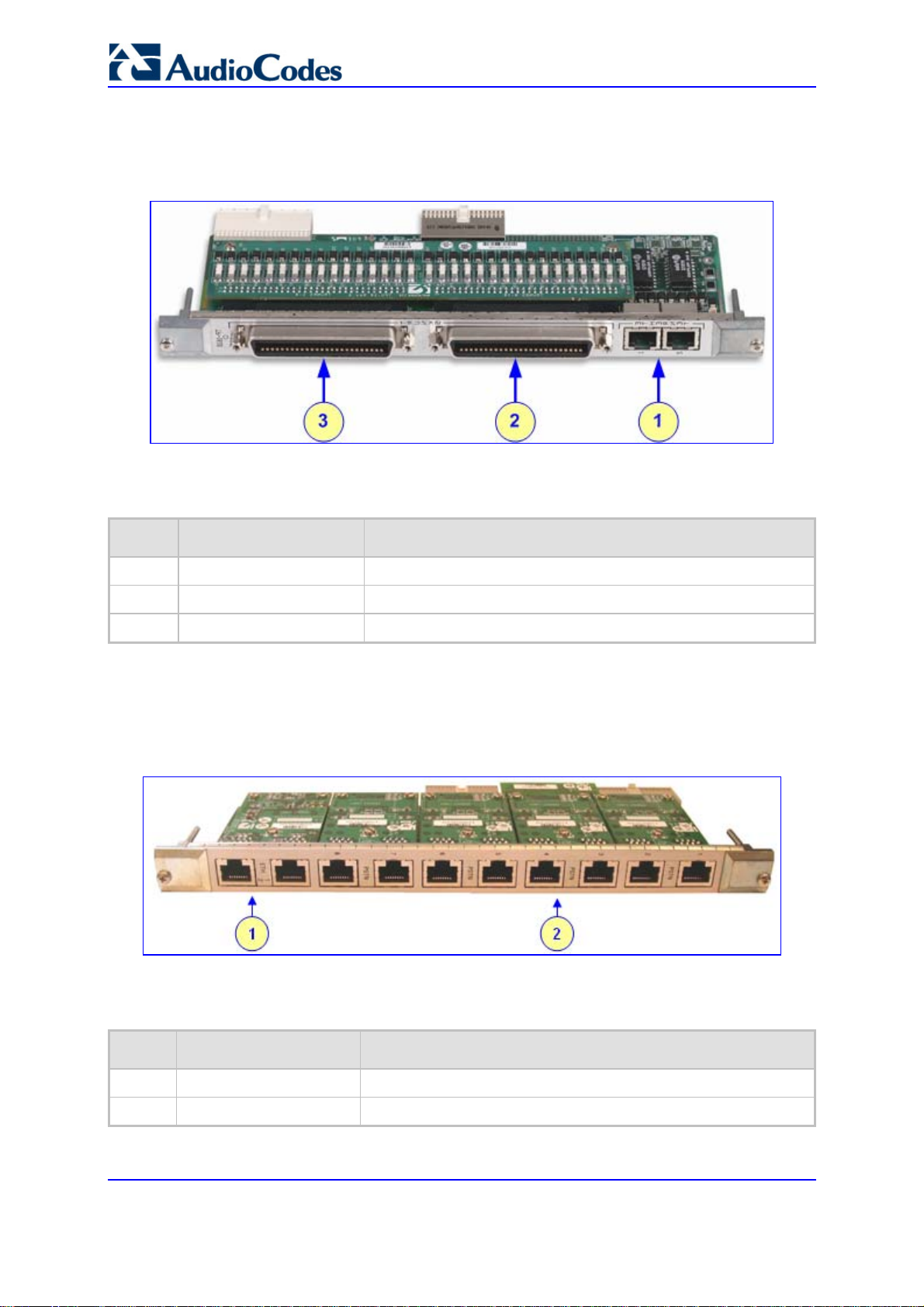
Mediant 2000 & TP-1610 & TP-260/UNI
16 E1/T1 spans: two 50-pin female Telco connectors (DDK 57AE-40500-21D), as
shown in the figure below:
Figure 2-3: RTM-1610 Rear Panel with two 50-pin Connectors for 16 Trunks
Table 2-8: Rear Panel with two 50-pin Connectors for 16 Trunks Component Descriptions
Item # Label Component Description
1
2
3
ETHERNET
TRUNKS
TRUNKS
Two Ethernet RJ-45 ports
50-pin female Telco connector for E1/T1 trunks 9 to 16
50-pin female Telco connector for E1/T1 trunks 1 to 8
1, 2, 4, or 8 E1/T1 spans: RJ-48c connectors per span. Note that the physical
difference between the 1-, 2-, and 4-span RTMs, and the 8-span RTM is that the RJ48c ports are depopulated correspondingly.
Figure 2-4: RTM-1610 with 8 RJ-48c Connectors for 8 Trunks
Table 2-9: Rear Panel with Eight RJ-48c Connectors for 8 Trunks Component Descriptions
Item # Label Component Description
1
2
ETHERNET
TRUNKS
2 RJ-45 Ethernet ports
8 RJ-48c E1/T-1 trunk connectors
SIP User's Manual 24 Document #: LTRT-68806
Page 25

SIP User's Manual 2. Physical Description
2.3 TP-260 Physical Description
The TP-260 blade is a complete plug-and-play device. The PC’s boot-up sequence
determines its I/O addresses and interrupts.
Figure 2-5: TP-260 Board Description
Table 2-10: TP-260 Component Description
Item # Component Description
1
2
3
4
5
6
7
Ethernet LEDs (refer to 'TP-260 LEDs' on page 26)
Reset button
Internally-located base blade LEDs (refer to 'TP-260 LEDs' on page 26)
Ethernet RJ-45 connector (for pinouts, refer to 'TP-260 Ethernet and E1/T1 Ports'
on page 27)
4 x T1/E1 RJ-48c trunk connectors (for pinouts, refer to 'TP-260 Ethernet and
E1/T1 Ports' on page 27)
E1/T/J1 LEDs (refer to 'TP-260 LEDs' on page 26)
Universal PCI, 32/64 bit, 33/66 MHz, and 3.3/5 V
Version 5.2 25 September 2007
Page 26

Mediant 2000 & TP-1610 & TP-260/UNI
2.3.1 TP-260 LEDs
The TP-260 LED descriptions are provided in the tables below.
Table 2-11: Ethernet LEDs Description
Label Color Status Description
Rx Yellow
Link Green
On Receiving data
On Ethernet connection is ON (Link)
Table 2-12: E1/T/J1 LEDs on the Front Panel (Bracket) Description
Label Color Status Description
Trunk Status 1
to 8
Green
Red
On Trunk is synchronized (normal operation)
On Loss due to one of the following signals:
LOS (Loss of Signal)
LFA (Loss of Frame Alignment)
AIS (Alarm Indication Signal -- 'Blue alarm')
RAI (Remote Alarm Indication -- 'Yellow alarm')
Table 2-13: Internally Located Base Blade LEDs Description
LED Name Color Description
LD1 COL
Red
Link collision. The LED toggles when there is a collision in the halfduplex operation.
LD2 SPEED
Orange
Link speed 10/100 Base-TX. The LED is ON for 100 Mbps and
OFF for 10 Mbps.
LD3 DUPLEX
Red
Link half-duplex or full-duplex. The LED is ON for full-duplex and
OFF for half-duplex.
LD4 TX
LD5 RS-232
LD6 FAIL
LD7 CLK40M
Orange
Red
Red
Red
Link Transmit. When the PHY transmits, the LED toggles.
Internal use only.
Indication from the TPM-1100.
When the LED toggles, the CLK40M for the PCI controller is active.
SIP User's Manual 26 Document #: LTRT-68806
Page 27
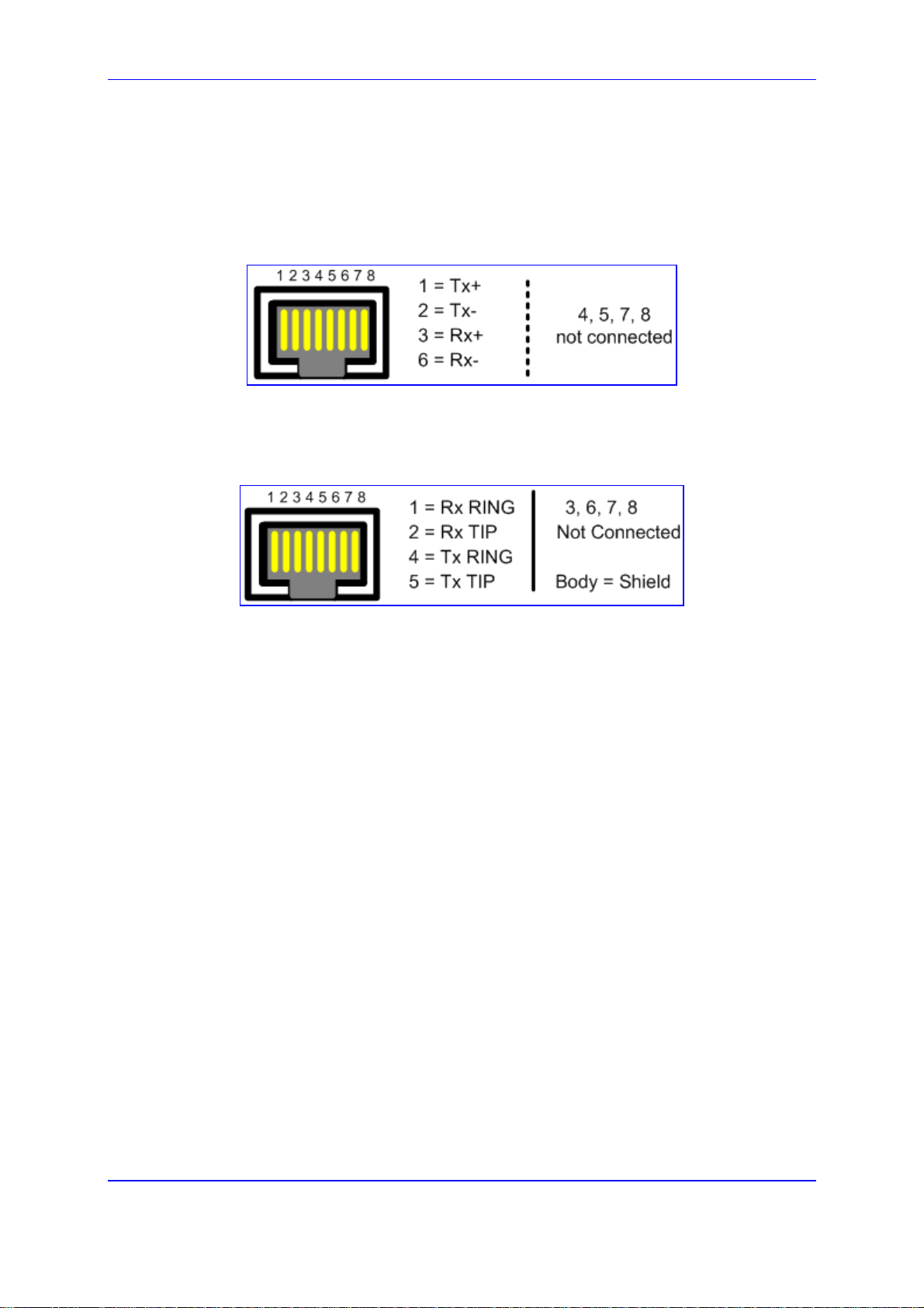
SIP User's Manual 2. Physical Description
2.3.2 TP-260 Ethernet and E1/T1 Ports
The Ethernet RJ-45 port connector pinouts are shown in the figure below:
Figure 2-6: RJ-45 Connector Pinouts
The E1/T1 RJ-48c port connector pinouts are shown in the figure below:
Figure 2-7: RJ-48c Connector Pinouts
Version 5.2 27 September 2007
Page 28

Mediant 2000 & TP-1610 & TP-260/UNI
Reader's Notes
SIP User's Manual 28 Document #: LTRT-68806
Page 29

SIP User's Manual 3. Installation
3 Installation
This section provides detailed information on the installation procedures for the following
products:
Mediant 2000 (refer to 'Installing the Mediant 2000' on page 29)
TP-1610 (refer to 'Installing the TP-1610' on page 40)
TP-260 (refer to 'Installing the TP-260' on page 43)
For information on how to start using the gateway, refer to 'Getting Started' on page 47.
Caution Electrical Shock
The equipment must only be installed or serviced by qualified service
personnel.
3.1 Installing the Mediant 2000
To install the Mediant 2000, perform the following installation steps in chronological order:
Unpack the Mediant 2000 (refer to 'Unpacking' on page 29)
Check the package contents (refer to 'Package Contents' on page 30)
Mount the Mediant 2000 (refer to 'Mounting the Mediant 2000' on page 30)
Cable the Mediant 2000 (refer to 'Cabling the Mediant 2000' on page 33)
After powering-up the Mediant 2000, the Ready and LAN LEDs on the front panel turn to
green (after a self-testing period of about 3 minutes). Any malfunction changes the Ready
LED to red (for details on the Mediant 2000 LEDs, refer to 'TP-1610 Front Panel LEDs' on
page 22).
When you have completed the above installation steps, you are ready to start configuring
the gateway (refer to 'Getting Started' on page 47).
3.1.1 Unpacking
Follow the procedure below for unpacking the received carton in which the Mediant 2000 is
shipped.
¾ To unpack the Mediant 2000, take these 6 steps:
1. Open the carton and remove packing materials.
2. Remove the Mediant 2000 from the carton.
3. Check that there is no equipment damage.
4. Check, retain and process any documents.
5. Notify AudioCodes or your local supplier of any damage or discrepancies.
6. Retain any diskettes or CDs.
Version 5.2 29 September 2007
Page 30

Mediant 2000 & TP-1610 & TP-260/UNI
3.1.2 Package Contents
Ensure that in addition to the Mediant 2000, the package contains:
For the dual AC power supply version two AC power cables are supplied; for the
single AC power supply version one AC power cable is supplied.
For the DC power supply version, one connectorized DC power cable (crimp
connection type) and one DC adaptor (screw connection type) connected to the rear
panel of the Mediant 2000 are supplied; use only one type.
The Mediant 2000 Fast Track Installation Guide.
CD (software and documentation).
Small plastic bag containing (refer to the figure below):
• Two brackets and four bracket-to-device screws for 19-inch rack installation
option.
• Four anti-slide bumpers for desktop / shelf installation option.
Figure 3-1: 19-inch Rack and Desktop Accessories
3.1.3 Mounting the Mediant 2000
The Mediant 2000 offers the following mounting options:
Desktop mounting (refer to 'Mounting Mediant 2000 on a Desktop' on page 31)
Installed in a standard 19-inch rack (refer to 'Installing Mediant 2000 in a 19-inch Rack'
SIP User's Manual 30 Document #: LTRT-68806
on page 31)
Page 31

SIP User's Manual 3. Installation
3.1.3.1 Mounting Mediant 2000 on a Desktop
The Mediant 2000 can be mounted on a desktop by attaching the four anti-slide bumpers
(supplied) to the underside of the Mediant 2000. Once you have attached these bumpers,
simply place it on the desktop in the position you require.
3.1.3.2 Installing Mediant 2000 in a 19-inch Rack
The Mediant 2000 can be installed in a standard 19-inch rack by implementing one of the
following methods:
Placing it on a pre-installed shelf in the rack (recommended method)
Attaching it directly to the rack’s frame using the Mediant 2000 front mounting
brackets and the user-adapted rear mounting brackets (not supplied). This method is
required for racks that don't provide shelves.
Rack Mount Safety Instructions (UL)
When installing the chassis in a rack, be sure to implement the following Safety
instructions recommended by Underwriters Laboratories:
• Elevated Operating Ambient Temperature: If installed in a closed or
multi-unit rack assembly, the operating ambient temperature of the rack
environment may be greater than room ambient temperature. Therefore,
consideration should be given to installing the equipment in an
environment compatible with the maximum ambient temperature (Tma)
specified by the manufacturer.
• Reduced Air Flow: Installation of the equipment in a rack should be
such that the amount of air flow required for safe operation on the
equipment is not compromised.
• Mechanical Loading: Mounting of the equipment in the rack should be
such that a hazardous condition is not achieved due to uneven
mechanical loading.
• Circuit Overloading: Consideration should be given to the connection of
the equipment to the supply circuit and the effect that overloading of the
circuits might have on overcurrent protection and supply wiring.
Appropriate consideration of equipment nameplate ratings should be
used when addressing this concern.
• Reliable Earthing: Reliable earthing of rack-mounted equipment should
be maintained. Particular attention should be given to supply connections
other than direct connections to the branch circuit (e.g., use of power
strips.)
Version 5.2 31 September 2007
Page 32

Mediant 2000 & TP-1610 & TP-260/UNI
Before rack-mounting the chassis, attach the two front mounting brackets (supplied) to the
front sides of the Mediant 2000, as described in the procedure below.
¾ To attach the two front side mounting brackets, take these 3 steps:
1. On one side of the Mediant 2000, remove the two screws located nearest the front
panel.
2. Align a bracket over the two holes from which you removed the screws in the step
above (so that the bracket’s larger holes face the front) and with the two replacement
screws (supplied), screw in the bracket.
3. Perform the same procedure on the other side of the Mediant 2000.
Figure 3-2: Front View with 19-inch Rack-Mount Brackets
¾ To install the Mediant 2000 in a 19-inch rack, take these 2 steps:
1. Position the device in your 19-inch rack and align the left-hand and right-hand bracket
holes to holes (of your choosing) in the vertical tracks of the 19-inch rack.
2. Use standard 19-inch rack bolts (not provided) to fasten the device to the frame of the
rack.
AudioCodes recommends using two additional rear mounting brackets (not supplied) for
added support.
Notes: If you are assembling the rear brackets by yourself, please note the following:
• The distance between the screws on each bracket is 26.5 mm.
• To attach the brackets, use 4-40 screws with a maximal box penetration
length of 3.5 mm.
¾ To mount the Mediant 2000 on a pre-installed shelf in a 19-inch
rack, take these 2 steps:
1. Place the Mediant 2000 on the pre-installed shelf.
2. You’re now recommended to take the optional steps of fastening the Mediant 2000 to
the frame of the rack (as described above) while it is placed on the shelf, so
preventing it from sliding when inserting cables into connectors on the rear panel.
SIP User's Manual 32 Document #: LTRT-68806
Page 33
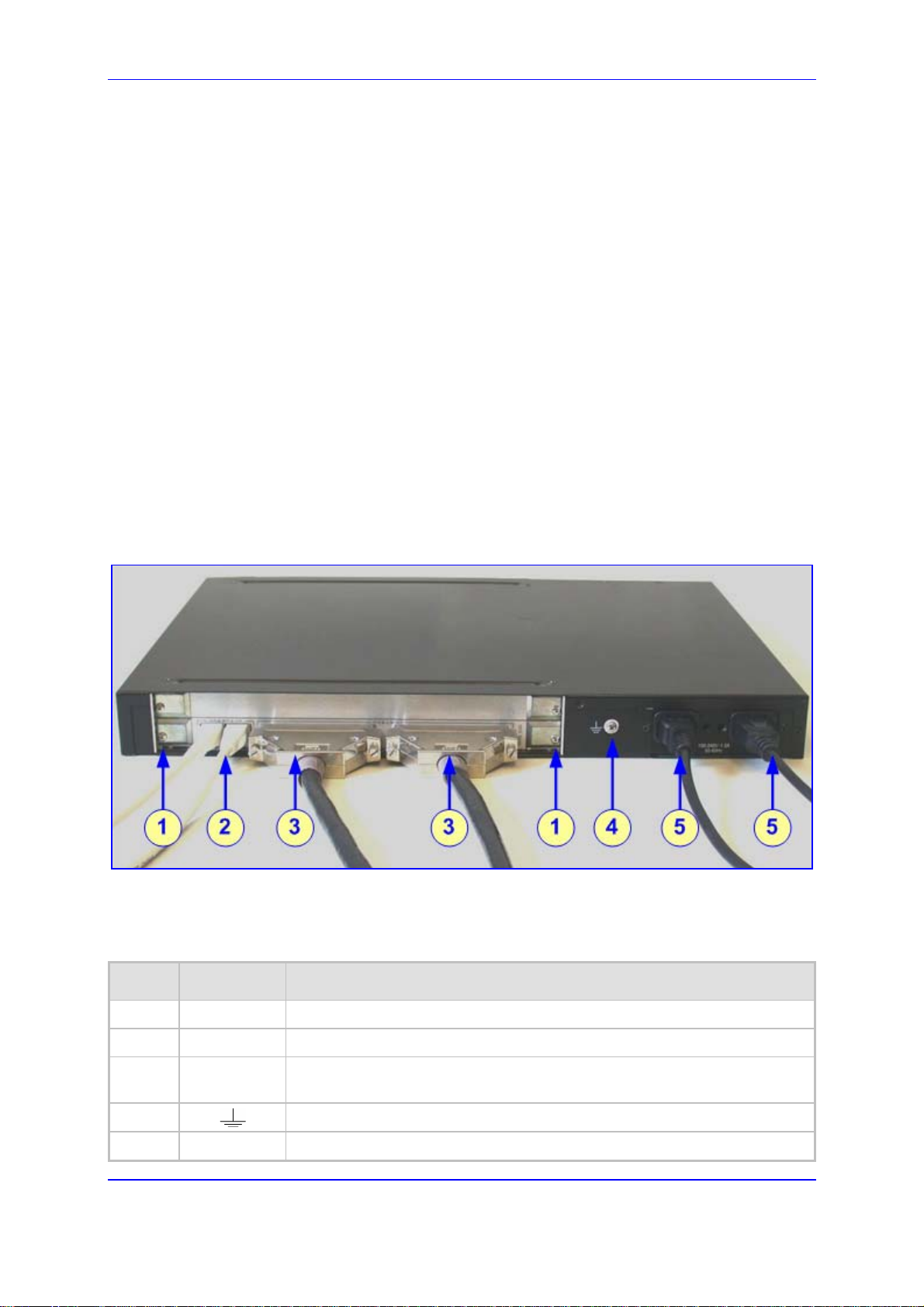
SIP User's Manual 3. Installation
3.1.4 Cabling the Mediant 2000
This section describes Mediant 2000 cabling, which includes the following:
Connecting the E1/T1 trunk interfaces (refer to 'Connecting the E1/T1 Trunk
Interfaces' on page 35)
Connecting the Ethernet interface (refer to 'Connecting the Ethernet Interface' on page
36)
Connecting the RS-232 port to a PC (refer to 'Connecting the RS-232 Port to a PC' on
page 37)
Connecting the power supply (refer to 'Connecting to the Power Supply' on page 38)
Refer to 'Physical Description' on page 19 for detailed information on the Mediant 2000
rear panel connectors and LEDs. Note that the Mediant 2000 is available in various
configurations, i.e., AC or DC power, and number of trunks (16-, 8-, 4-, 2-, or 1-trunk
device).
The figure below shows an example of the rear-panel cabling for Mediant 2000 providing
16 trunks and supporting dual AC power.
Figure 3-3: Rear-Panel Cabling (e.g., 16 Trunks, Dual AC Power)
Table 3-1: Mediant 2000 Rear Panel Cabling (16 Trunks, Dual AC Power) Component
Descriptions
Item # Label Component Description
1 -- RTM locking screws
2
3
4
5
Version 5.2 33 September 2007
ETHERNET
TRUNKS
100-240~1.5A
Two Category 5 network cables, connected to the 2 Ethernet RJ-45 ports
Two 50-pin Telco connector cables (of at least 26 AWG UTP), each
supporting 8 trunks
Protective earthing screw
Dual AC power cables
Page 34
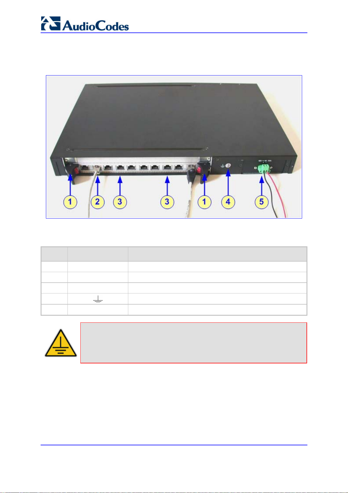
Mediant 2000 & TP-1610 & TP-260/UNI
The figure below shows an example of the rear-panel cabling for Mediant 2000 providing
eight trunks and supporting DC power.
Figure 3-4: Rear-Panel Cabling (8 Trunks, DC Power)
Table 3-2: Mediant 2000 Rear Panel Cabling (8 Trunks, DC Power) Component Descriptions
Item # Label Component Description
1 -- RTM latches
2
3
4
5
ETH
PSTN
48V 4A max
A Category 5 network cable, connected to the Ethernet 1 RJ-45 port
8 RJ-48c ports, each supporting a trunk
Protective earthing screw
2-pin connector for DC
Electrical Earthing
The unit must be permanently connected to earth via the screw provided at the
back on the unit. Use 14-16 AWG wire and a proper ring terminal for the
earthing.
SIP User's Manual 34 Document #: LTRT-68806
Page 35

SIP User's Manual 3. Installation
3.1.4.1 Grounding the Mediant 2000
Permanently connect the device to a suitable earth with the protective earthing screw on
the rear connector panel, using 14-16 AWG wire.
Electrical Earthing
The unit must be permanently connected to earth via the screw provided at the
back on the unit. Use 14-16 AWG wire and a proper ring terminal for the
earthing.
3.1.4.2 Connecting the E1/T1 Trunk Interfaces
Connect the E1/T1 Trunk interfaces using either Telco (for Mediant 2000 with 16 spans) or
RJ-48 (for Mediant 2000 with 1, 2, 4, or 8 spans) connectors:
¾ To connect E1/T1 trunks using 50-pin Telco connectors (16-trunk
device), take these 3 steps:
1. Attach the Trunk cable (of at least 26 AWG UTP) with a 50-pin male Telco connector
to the 50-pin female Telco connector labeled Trunks 18 on the Mediant 2000 Rear
Transition Module (RTM).
2. Connect the other end of the Trunk cable to the PBX/PSTN switch.
3. Repeat steps 1 and 2 for the other Trunk cable, but this time connect it to the
connector labeled Trunks 916.
The 50-pin male Telco cable connector must be wired according to the pinout in the table
below, and to mate with the female connector illustrated in the figure below.
Figure 3-5: 50-pin Female Telco Board-Mounted Connector
Table 3-3: E1/T1 Connections on each 50-pin Telco Connector
E1/T1 Trunk Number
Tx Pins (Tip/Ring) Rx Pins (Tip/Ring)
1 to 8 9 to 16
1 9 27/2 26/1
2 10 29/4 28/3
3 11 31/6 30/5
4 12 33/8 32/7
Version 5.2 35 September 2007
Page 36

Mediant 2000 & TP-1610 & TP-260/UNI
Table 3-3: E1/T1 Connections on each 50-pin Telco Connector
E1/T1 Trunk Number
Tx Pins (Tip/Ring) Rx Pins (Tip/Ring)
1 to 8 9 to 16
5 13 35/10 34/9
6 14 37/12 36/11
7 15 39/14 38/13
8 16 41/16 40/15
¾ To connect E1/T1 trunks using RJ-48c connectors (1-, 2-, 4-, 8-
trunk device) take these 2 steps:
1. Connect the E1/T1 trunk cables to the ports labeled Trunks 1 to 8 (in the case of the
8-trunk device) on the Mediant 2000 RTM.
2. Connect the other ends of the Trunk cables to the PBX/PSTN switch.
RJ-48c trunk connectors are wired according to the figure below.
Figure 3-6: RJ-48c Connector Pinouts
3.1.4.3 Connecting the Ethernet Interface
TheMediant 2000 provides two 10/100Base-TX RJ-45 ports for connection to the Ethernet
network. The dual ports provide Ethernet redundancy. Follow the procedure below for
connecting to the Ethernet network.
¾ To connect the Ethernet interface, take these 3 steps:
1. Connect a standard Category 5 network cable to the Ethernet RJ-45 port (labeled
ETHERNET).
2. Connect the other end of the Category 5 network cables to your IP network.
3. For Ethernet redundancy/backup, repeat steps 1 and 2 for the second Ethernet port.
When assigning an IP address to the gateway using HTTP (in Section Error! Reference
source not found.), you may be required to disconnect the Ethernet cable and re-cable it
differently.
Note: For Ethernet redundancy, it's recommended to connect each of the Ethernet
connectors to a different switch.
SIP User's Manual 36 Document #: LTRT-68806
Page 37

SIP User's Manual 3. Installation
The Ethernet connectors are wired according to the figure below.
Figure 3-7: RJ-45 Connector Pinouts
3.1.4.4 Connecting the RS-232 Port to a PC
Follow the procedure below to connect the Mediant 2000 serial (RS-232) interface to a PC.
Note: The RS-232 port is available only on the 1, 2 and 4-span Mediant 2000
configuration.
¾ To connect Mediant 2000 RS-232 interface to a PC, take these 2
steps:
1. Connect the DB-9 connector, on one end of the straight-through RS-232 cable, to the
Mediant 2000 RS-232 port (Labeled I0I0).
2. Connect the DB-9 connector at the other end of the cable, to either the COM1 or
COM2 RS-232 communication port on your PC.
The RS-232 cable connector pinouts are shown in the figure below:
Figure 3-8: RS-232 Connector Pinouts
For information on establishing a serial communications link with the gateway, refer to
Establishing a Serial Communications Link with the Mediant 2000.
Version 5.2 37 September 2007
Page 38

Mediant 2000 & TP-1610 & TP-260/UNI
3.1.4.5 Connecting the Power Suppl y
The Mediant 2000 connection to the power supply depends on the supported hardware
configuration:
Single or dual AC power (refer to 'Connecting the AC Power Supply' on page 38)
DC power (refer to 'Connecting the DC Power Supply' on page 38)
3.1.4.5.1 Connecting the AC Power Supply
The Mediant 2000 can support up to two AC power interfaces (single or dual).
¾ To connect the Mediant 2000 single AC power cable, take these 2
steps:
1. Attach one end of the 100/240 VAC power cable (supplied) to the rear AC socket.
2. Connect the other end of the power cable to the correct earthed AC power supply.
¾ To connect the Mediant 2000 dual AC power cable, take these 2
steps:
1. Attach one end of the 100/240 VAC power cables (supplied) to the rear AC sockets.
2. Connect the other end to a separate earthed mains circuits (for power source
redundancy).
Note: For the dual AC power supply, please note the following:
• The LED on the left side of the chassis is only connected when the dual
AC is used. It is not relevant to the single AC power connection.
• If only a single socket is connected to the AC power, (while the other plug
is left unconnected), the chassis’ LED (on the left side) is lit Red,
indicating that one of the dual power inlets is disconnected.
• When both the AC power cables are connected, one of the plugs can be
disconnected under power without affecting operation, in which case the
chassis’ left LED is lit Red.
• A UPS can be connected to either (or both) of the AC connections.
• The dual AC connections operate in a 1 + 1 configuration and provide
load-sharing redundancy.
• Each of the dual power cables can be connected to different AC power
phases.
3.1.4.5.2 Connecting the DC Power Supply
The Mediant 2000 can connect to the DC power supply using one of the following methods:
DC Terminal block with a screw connection type
DC Terminal block with a crimp connection type
SIP User's Manual 38 Document #: LTRT-68806
Page 39

SIP User's Manual 3. Installation
¾ To connect Mediant 2000 using a DC terminal block screw
connector, take these 3 steps:
1. Create a DC cable by inserting two 14-16 AWG insulated wires into the supplied
adaptor (refer to the figure below) and fasten the two screws, each one located
directly above each wire.
2. Connect the two insulated wires to the correct DC power supply. Ensure that the
connections to the DC power supply maintain the correct polarity.
3. Insert the terminal block into the DC inlet located on the Mediant 2000.
Figure 3-9: DC Power Terminal Block Screw Connector
¾ To connect Mediant 2000 using a DC terminal block crimp
connector, take these 3 steps:
1. Remove the DC adaptor (screw connection type) that is attached to the Mediant 2000
rear panel.
2. Connect the two insulated wires to the correct DC power supply. Ensure that the
connections to the DC power supply maintain the correct polarity (refer to the figure
below).
3. Insert the terminal block into the DC inlet located on the Mediant 2000.
Figure 3-10: DC Power Terminal Block Crimp Connector
Version 5.2 39 September 2007
Page 40

Mediant 2000 & TP-1610 & TP-260/UNI
3.2 Installing the TP-1610
Electrical Earthing
Prior to installation of any blade in a chassis, always correctly connect the
chassis to a safety ground according to the laws and regulations of the country
in which the installation is performed.
Electrical Component Sensitivity
Electronic components on printed circuit boards (PCB) are extremely sensitive
to static electricity. Normal amounts of static electricity generated by clothing
can damage electronic equipment. To reduce the risk of damage due to
electrostatic discharge when installing or servicing electronic equipment, it is
recommended that anti-static earthing straps and mats be used.
To install the TP-1610, take these four chronological steps:
Unpack the TP-1610 (refer to 'Unpacking' on page 40)
Check the package contents (refer to 'Package Contents' on page 41)
Install the TP-1610 in a compactPCI™ chassis (refer to 'Installing the TP-1610' on
page 41)
Cable the TP-1610 (refer to 'Cabling the TP-1610' on page 42)
When you have completed the above installation steps, you are then ready to start
configuring the gateway (refer to 'Web-based Management' on page 57).
3.2.1 Unpacking
Follow the procedure below for unpacking the received carton in which the TP-1610 is
shipped.
¾ To unpack the TP-1610, take these 6 steps:
1. Open the carton and remove packing materials.
2. Remove the TP-1610 blade from the carton.
3. Check that there is no equipment damage.
4. Check, retain, and process any documents.
5. Notify AudioCodes or your local supplier of any damage or discrepancies.
6. Retain any diskettes or CDs.
SIP User's Manual 40 Document #: LTRT-68806
Page 41

SIP User's Manual 3. Installation
3.2.2 Package Contents
Ensure that in addition to the TP-1610, the package contains:
An RTM blade (optional)
CD (software and documentation)
This User’s Manual
Release Notes
3.2.3 Installing the TP-1610
The TP-1610 cPCI blade is hot-swappable and can therefore be removed from a slot (and
inserted into a slot) while the chassis is under power. It is recommended though that you
power down the chassis and read the notes below before replacing the components.
Notes:
• Before removing or inserting blades from / to the chassis, attach a wrist
strap for electrostatic discharge (ESD) and connect it to the rack frame
3.2.3.1 Inserting Blades
The TP-1610 blade (and its associated Rear Transition Module -- RTM -- blade) is
designed to be hosted in chassis (i.e., Mediant 2000 and third-party chassis) that comply
with form factor 6U PICMG 2.0 single cPCI slots.
using an alligator clip.
• Do not set components down without protecting them with a static bag.
¾ To insert the TP-1610 blade into the chassis, take these 2 steps:
1. Choose an available slot in a compactPCI™ chassis and gently insert the TP-1610
blade into it; as the TP-1610 blade is inserted, the black plastic handles, at both ends
of the blade’s front panel, must engage with the chassis. When the TP-1610 blade is
firmly mounted into the correct position inside the chassis, the red plastic latches
within each handle self-lock (this also ensures that the TP-1610 blade is properly
earthed via the chassis).
2. Fasten the screws on the front panel of the blade to secure the blade to the chassis.
¾ To insert the TP-1610 RTM into the chassis, take these 2 steps:
1. Choose an available slot in a compactPCI™ chassis and gently insert the TP-1610
RTM into it; as the TP-1610 RTM is inserted, the black plastic handles, at both ends of
the blade’s panel, must engage with the chassis. When the TP-1610 RTM is firmly
mounted into the correct position inside the chassis, the red plastic latches within each
handle self-lock (this also ensures that the TP-1610 blade is properly earthed via the
chassis).
Version 5.2 41 September 2007
2. Fasten the screws on the front panel of the blade to secure the blade to the chassis.
Page 42

Mediant 2000 & TP-1610 & TP-260/UNI
3.2.3.2 Removing Blades
Follow the procedures below for removing the TP-1610 and its associated RTM blade.
¾ To remove the TP-1610 blade from the chassis, take these 3 steps:
1. Unfasten the screws on the plate of the blade.
2. Press the red ejector buttons on the two black ejector/injector latches on both ends
and wait for the hot-swap blue LED to light, indicating that the blade can be removed.
3. Pull on the two ejector/injector latches and ease out the blade from the slot.
¾ To remove the TP-1610 RTM from the chassis, take these 4 steps:
1. Remove the cables attached to the RTM.
2. Unfasten the screws on the brackets at both ends of the panel that secure the RTM to
the chassis.
3. Press the red ejector buttons on the two black ejector/injector latches on both ends.
4. Grasp the panel and ease the RTM blade out of the slot.
3.2.4 Cabling the TP-1610
The cabling for the TP-1610 is listed below:
Connect the E1/T1 trunk interfaces (refer to 'Connecting the E1/T1 Trunk Interfaces'
on page 35)
Install the Ethernet connection (refer to 'Installing the Ethernet Connection' on page
36)
Optionally, connect the TP-1610 RS-232 port to your PC (refer to 'Connecting the RS-
232 Port to a PC' on page 37)
SIP User's Manual 42 Document #: LTRT-68806
Page 43

SIP User's Manual 3. Installation
3.3 Installing the TP-260
This section describes the TP-260 blade cabling, which includes the following:
Unpacking the TP-260(refer to 'Unpacking' on page 43)
Checking the package contents (refer to 'Package Contents' on page 44)
Installing the TP-260 in your PC (refer to 'Installing the TP-260' on page 44)
Cabling the TP-260 (refer to 'Cabling the TP-260' on page 44)
When you have completed the above installation steps, you are then ready to start
configuring the gateway (refer to 'Web-based Management' on page 57).
Electrical Earthing
Prior to installation of any blade in a chassis, always correctly connect the
chassis to a safety ground according to the laws and regulations of the country
in which the installation is performed.
Electronic components on printed circuit boards (PCB) are extremely sensitive
to static electricity. Normal amounts of static electricity generated by clothing
can damage electronic equipment. To reduce the risk of damage due to
electrostatic discharge when installing or servicing electronic equipment, it is
recommended that anti-static earthing straps and mats be used.
3.3.1 Unpacking
Follow the procedure below for unpacking the received carton in which the TP-260 is
shipped.
¾ To unpack the TP-260, take these 6 steps:
1. Open the carton and remove packing materials.
2. Remove the TP-260 board from the carton.
3. Check that there is no equipment damage.
4. Check, retain and process any documents.
5. Notify AudioCodes or your local supplier of any damage or discrepancies.
Electrical Component Sensitivity
Version 5.2 43 September 2007
6. Retain any diskettes or CDs.
Page 44

Mediant 2000 & TP-1610 & TP-260/UNI
3.3.2 Package Contents
Ensure that in addition to the TP-260, the package contains:
Four E1/T1 cable splitters (relevant for the 8 span version only)
CD (software and documentation)
This User’s Manual
Release Notes
3.3.3 Installing the TP-260
The TP-260 is a Peripheral Component Interconnect-based (PCI) blade designed for hosts
such as PCs. The procedure below describes how to install the blade in a PC.
¾ To install the TP-260 blade, take these 8 steps:
1. End all applications running on the PC.
2. Shut down the PC, turn off the power, and then remove the PC's cover.
3. Choose an available PCI slot and remove its blank rear bracket.
4. Insert the TP-260 blade into the chosen PCI slot. Ensure that the front panel (bracket)
of the TP-260 blade fits correctly into the opening in the rear panel of the PC's
chassis. In addition, ensure that the edge of the PCI retainer bracket fits correctly into
the PC’s PCI slot.
5. Secure the front panel of the TP-260 blade into the chassis frame with a standard
screw. This also ensures chassis ground to the TP-260 blade.
6. Replace and secure the PC's cover.
7. Power up the PC.
8. When using Windows
been found. The driver for the TP-260 is located in the supplied software package
(260_UNSeries.inf).
Note that since the TP-260 PCI gateway operates independently and relies only on
the host’s PCI for its power, the driver is only used to prevent the Found new
Hardware Wizard to reappear each time the host PC restarts.
TM
operating systems, the PC prompts that new hardware has
3.3.4 Cabling the TP-260
This section describes TP-260 cabling, which includes the following:
Connecting the E1/T1 trunk interfaces (refer to 'Connecting the E1/T1 Trunk
Interfaces' on page 45)
Connecting the Ethernet interface (refer to 'Connecting the Ethernet Interface' on page
SIP User's Manual 44 Document #: LTRT-68806
46)
Page 45

SIP User's Manual 3. Installation
3.3.4.1 Connecting the E1/T1 Trunk Interfaces
The TP-260 provides four RJ-48c ports for supporting up to eight E1/T1 spans.
¾ To cable the TP-260, take these 2 steps:
1. Connect the TP-260 E1/T1 interfaces to your E1/T1 trunks by using the four supplied
TP-260 E1/T1 cable splitters (shown in the figure below). Connect a splitter to each of
the four RJ-48 connectors labeled Trunks 1/5, 2/6, 3/7 and 4/8 on the TP-260 front
panel. Each splitter distributes each RJ-48 connector into two separate connectors
(wired according to the figure below): the first connector (labeled 1/4) on each splitter
supports each of the first four trunks, the second connector (labeled 5/8) on each
splitter supports each of the last four trunks.
Figure 3-11: RJ-48c Connector Pinouts
Note: The TP-260 E1/T1 cable splitter is part of the 8-span TP-260 product and is
PSTN certified. When using a non-AudioCodes E1/T1 cable splitter,
AudioCodes cannot guarantee compliance with PSTN homologations.
Figure 3-12: E1/T1 Cable Splitter
Version 5.2 45 September 2007
Page 46

Mediant 2000 & TP-1610 & TP-260/UNI
3.3.4.2 Connecting the Ethernet Interface
Connect the TP-260 Ethernet connection, located on the front panel, directly to the network
using a standard RJ-45 Ethernet cable. The Ethernet connector is wired according to the
connector pinouts shown below:
Figure 3-13: RJ-45 Connector Pinouts
Note that when assigning an IP address to the TP-260 using HTTP (in 'Assigning an IP
Address Using HTTP' on page 50), you may be required to disconnect this cable and recable it differently.
SIP User's Manual 46 Document #: LTRT-68806
Page 47

SIP User's Manual 4. Getting Started
4 Getting Started
The gateway is supplied with default networking parameters (i.e., MAC and IP addresses,
as listed in the table below) and with an application software (cmp file) residing on its flash
memory (with factory default parameters).
The gateway is composed of one or two identical gateway modules. These gateway
modules are fully independent, each having its own MAC and IP address.
Note: If the Mediant 2000 or TP-1610 consists of two gateway modules, the IP
addresses assigned to these modules must be in the same subnet.
Before you begin configuring the gateway, refer to 'Configuration Concepts' on page 47 for
a description of the available gateway configuration methods. Using a preferred method,
change the gateway's default IP address to correspond with your network environment
(refer to 'Assigning an IP Address' on page 50).
For information on quickly setting up the gateway with basic parameters using a standard
Web browser, refer to 'Configuring the Basic Parameters' on page 54.
Table 4-1: Default Networking Parameters
Parameter Default Value
Mediant 2000 and TP-1610 with a single module (up to 8
IP Address
trunks); TP-260: 10.1.10.10
Mediant 2000 and TP-1610 with a double module (16 trunks):
10.1.10.10 (trunks 1 - 8) and 10.1.10.11 (trunks 9 - 16)
Subnet Mask
Default Gateway IP Address
255.255.0.0
0.0.0.0
4.1 Configuration Concepts
You can deploy the gateway in a wide variety of applications enabled by its parameters
and configuration files (e.g., Call Progress Tones). The parameters can be configured and
configuration files can be loaded using the following tools:
A standard Web browser (described in 'Web-based Management' on page 57).
A configuration file referred to as the ini file. For information on how to use the ini file,
refer to 'ini File Configuration' on page 267.
An SNMP browser software (refer to the SIP Series Reference Manual).
AudioCodes’ Element Management System (refer to AudioCodes’ EMS User’s Manual
or EMS Product Description).
To upgrade the gateway (i.e., load new software or configuration files), use the gateway's
Embedded Web Server's Software Upgrade Wizard (refer to 'Software Upgrade Wizard' on
page 240), or alternatively, use the BootP/TFTP configuration utility (refer to the SIP Series
Reference Manual).
Version 5.2 47 September 2007
Page 48

Mediant 2000 & TP-1610 & TP-260/UNI
4.2 Startup Process
The startup process (illustrated in the following figure) begins when the gateway is reset
(physically, using the Embedded Web Server, or using SNMP) and ends when the
operational software is running. In the startup process, the network parameters, and
software and configuration files are obtained.
After the gateway powers up or after it's physically reset, it broadcasts a BootRequest
message to the network. If it receives a reply (from a BootP server), it changes its network
parameters (IP address, subnet mask and default gateway address) to the values
provided. If there is no reply from a BootP server and if DHCP is enabled (DHCPEnable =
1), the gateway initiates a standard DHCP procedure to configure its network parameters.
After changing the network parameters, the gateway attempts to load the cmp and various
configuration files from the TFTP server’s IP address, received from the BootP/DHCP
servers. If a TFTP server’s IP address isn’t received, the gateway attempts to load the
software (cmp) file and / or configuration files from a preconfigured TFTP server (refer to
'Automatic Update Mechanism' on page 245). Thus, the gateway can obtain its network
parameters from BootP or DHCP servers, and its software and configuration files from a
different TFTP server (preconfigured in the ini file).
If BootP/DHCP servers are not located or when the gateway is reset using the Embedded
Web Server or SNMP, it retains its network parameters and attempts to load the software
(cmp) file and / or configuration files from a preconfigured TFTP server. If a preconfigured
TFTP server doesn’t exist, the gateway operates using the existing software and
configuration files loaded on its non-volatile memory.
Note that after the operational software runs and if DHCP is configured, the gateway
attempts to renew its lease with the DHCP server.
Notes:
• Though DHCP and BootP servers are very similar in operation, the
DHCP server includes some differences that could prevent its operation
with BootP clients. However, many DHCP servers such as Windows™ NT
DHCP server are backward-compatible with BootP protocol and can be
used for gateway configuration.
• By default, the duration between BootP/DHCP requests is one second
(configured by the BootPDelay ini file parameter). The number of
requests is three by default (configured by the BootPRetries ini file
parameter). Both parameters can also be set using the BootP command
line switches.
SIP User's Manual 48 Document #: LTRT-68806
Page 49
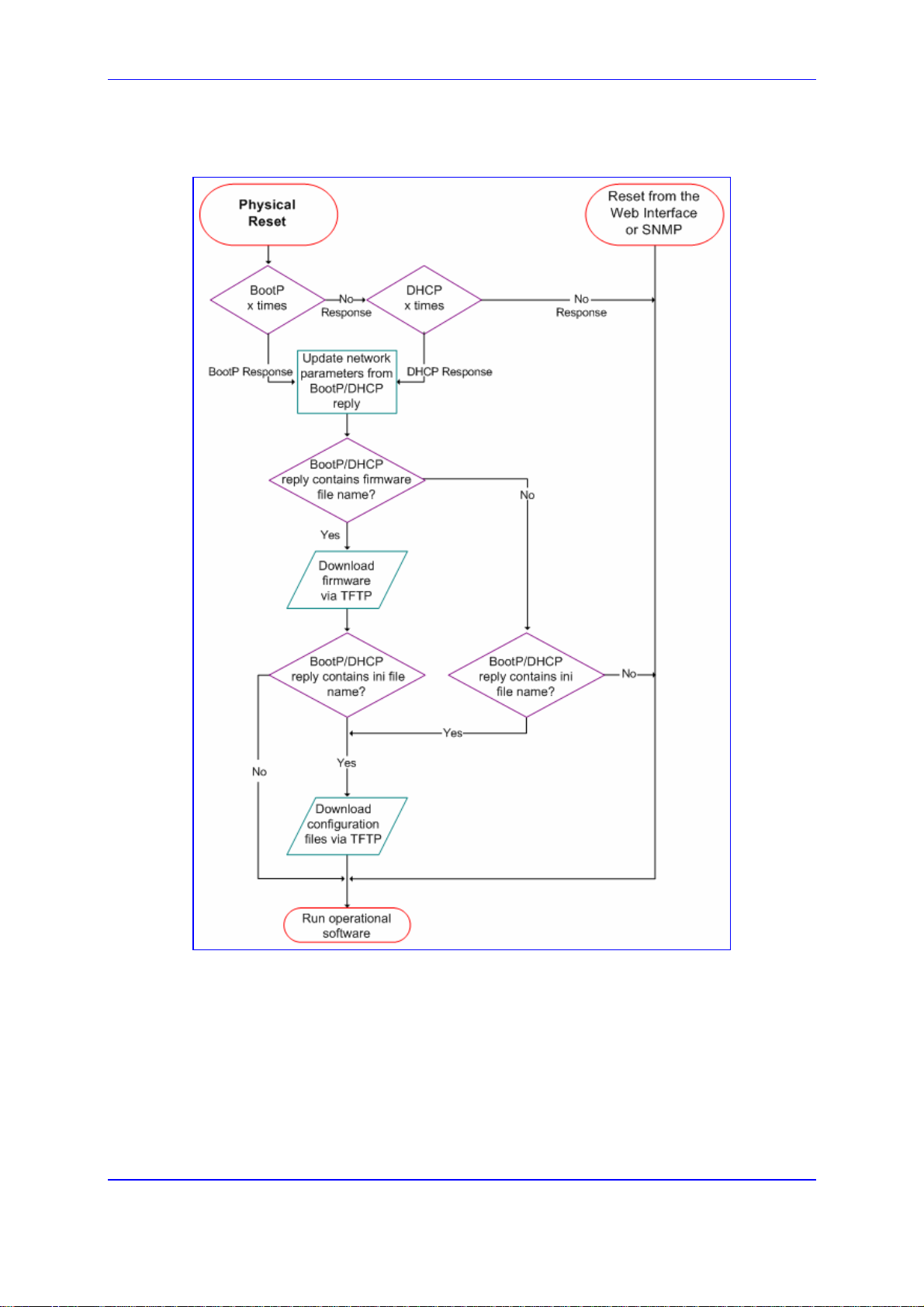
SIP User's Manual 4. Getting Started
Figure 4-1: Startup Process
Version 5.2 49 September 2007
Page 50

Mediant 2000 & TP-1610 & TP-260/UNI
4.3 Assigning an IP Address
To assign the gateway an IP address, use one of the following methods:
HTTP using a Web browser (refer to 'Assigning an IP Address Using HTTP' on page
50).
BootP (refer to 'Assigning an IP Address Using BootP' on page 51).
Embedded Command Line Interface (CLI) accessed via RS-232 (if supported) or
Telnet (refer to 'Assigning an IP Address Using the CLI' on page 51).
Dynamic Host Control Protocol (DHCP) (refer to the SIP Series Reference Manual).
Use the hardware Reset button at any time to restore the gateway's networking parameters
to their factory default values (refer to 'Restoring Default Settings' on page 260).
4.3.1 Assigning an IP Address Using HTTP
You can assign the gateway an IP address using the gateway's HTTP-based Embedded
Web Server.
¾ To assign an IP address using HTTP, take these 9 steps:
1. Disconnect the gateway from the network and reconnect it to a PC using one of the
following two methods:
• Connect the network interface on your PC to a port on a network hub / switch,
using a standard Ethernet cable. Connect the gateway to another port on the
same network hub / switch, using a second standard Ethernet cable.
• Connect the network interface on your PC directly to the gateway, using an
Ethernet cross-over cable.
2. Change your PC’s IP address and subnet mask to correspond with the gateway's
factory default IP address and subnet mask (for default IP addresses, refer to 'Getting
Started' on page 47).
3. Access the gateway's Embedded Web Server (refer to 'Accessing the Embedded Web
Server' on page 60).
4. Access the ‘Quick Setup’ screen by clicking the Quick Setup menu.
5. Define the gateway's ‘IP Address’, ‘Subnet Mask’, and ‘Default Gateway IP Address’
fields to correspond with your network IP settings.
6. Click the Reset button, and then at the prompt, click OK; the gateway applies the
changes and restarts. When implementing Mediant 2000 with two modules, repeat
steps 3 to 5 for the second module; otherwise, skip to Step 7.
7. Disconnect your PC from the gateway or from the hub / switch (depending on the
connection method used in Step 1).
8. Reconnect the gateway and your PC (if necessary) to the network.
9. Restore your PC’s IP address and subnet mask to their original settings. If necessary,
restart your PC and re-access the gateway via the Embedded Web Server with its
newly assigned IP address.
SIP User's Manual 50 Document #: LTRT-68806
Page 51
SIP User's Manual 4. Getting Started
Tip: Record and retain the IP address and subnet mask you assign the gateway.
Do the same when defining new username or password. If the Embedded
Web Server is unavailable (for example, if you’ve lost your username and
password), use the BootP/TFTP (Trivial File Transfer Protocol) configuration
utility to access the device, ‘reflash’ the load and reset the password (refer to
the SIP Series Reference Manual). For detailed information on using a
BootP/TFTP configuration utility to access the device).
4.3.2 Assigning an IP Address Using BootP
The procedure below describes how to assign the gateway an IP address using the
supplied BootP application. For a detailed description on using AudioCodes' BootP
application, refer to the SIP Series Reference Manual.
Note: BootP procedure can also be performed using any standard compatible
BootP server.
Tip: You can also use BootP to load the auxiliary files to the gateway (refer to the
SIP Series Reference Manual).
¾ To assign an IP address using BootP, take these 3 steps:
1. Open the BootP application (supplied with the gateway's software package).
2. Add a client configuration for the gateway that you want to initialize.
3. Press the gateway's hardware Reset button to physically reset the gateway so that it
uses BootP; the gateway changes its network parameters to the values provided by
the BootP.
Repeat steps 2 through 3 for the gateway's second module (if used).
4.3.3 Assigning an IP Address Using the CLI
Assigning an IP address using the command-line interface (CLI) is performed in two
stages:
1. Accessing the CLI (refer to 'Accessing the CLI' on page 52) using a standard Telnet
application or serial communication software (e.g., HyperTerminal
RS-232 port (if supported).
TM
) connected to the
2. Assigning an IP address to the gateway (refer to 'Assigning an IP Address' on page
53).
Version 5.2 51 September 2007
Page 52

4.3.3.1 Accessing the CLI
The procedure below describes how to access the CLI using either Telnet or RS-232
interface (if supported).
¾ To access the CLI using the embedded Telnet server, take these 3
steps:
1. Enable the embedded Telnet server, by performing the following:
a. Access the gateway's Embedded Web Server (refer to 'Accessing the Embedded
Web Server' on page 60).
b. Open the 'Application Settings' screen (Advanced Configuration menu >
Network Settings > Application Settings option), and therein set the parameter
‘Embedded Telnet Server’ to ‘Enable (Unsecured)’ or ‘Enable Secured (SSL)’.
For detailed information, refer to 'Configuring the Application Settings' on page
157.
c. Save these settings to the flash memory and reset the gateway by performing the
following:
a. Click the Maintenance button on the main menu bar; the 'Maintenance
Actions' screen is displayed.
b. From the 'Burn to FLASH' drop-down list, select 'Yes', and then click the
Reset button; the gateway shuts down and restarts.
Mediant 2000 & TP-1610 & TP-260/UNI
2. Use a standard Telnet application to connect to the gateway's embedded Telnet
server. Note that if the Telnet server is set to SSL mode, a special Telnet client is
required on your PC to connect to the Telnet interface over a secured connection.
3. Login using the default username (‘Admin’) and password (‘Admin’).
The procedure below describes how to establish a serial communications link with the
gateway (using serial communication software such as HyperTerminal
TM
) through the RS-
232 interface.
¾ To access the CLI using the RS-232 port (if supported), take these
2 steps:
1. Connect the gateway's RS-232 port to your PC (refer to Connecting the RS-232 Port
to Your PC on page 37.
TM
2. Use a serial communication software (e.g., HyperTerminal
communications port settings:
• Baud Rate: 115,200 bps
• Data bits: 8
• Parity: None
• Stop bits: 1
) with the following
• Flow control: None
The CLI prompt appears.
Note: The TP-1610 and TP-260 don't provide an RS-232 port.
SIP User's Manual 52 Document #: LTRT-68806
Page 53

SIP User's Manual 4. Getting Started
4.3.3.2 Assigning an IP Address
Once you have accessed the CLI, follow the procedure below for assigning a new IP
address.
¾ To assign an IP address via the CLI, take these 4 steps:
1. At the prompt, type conf, and then press <Enter>; the configuration folder is
accessed.
2. To view the current network parameters, at the prompt, type GCP IP, and then press
<Enter>; the current network settings are displayed.
3. Change the network settings by typing the following:
SCP IP [ip_address] [subnet_mask] [default_gateway]
For example,
SCP IP 10.13.77.7 255.255.0.0 10.13.0.1
The new settings take effect on-the-fly. Connectivity is active at the new IP address.
Note: This command requires you to enter all three network parameters (each
separated by a space).
4. To save the configuration, at the prompt, type SAR, and then press <Enter>; the
gateway restarts with the new network settings.
Version 5.2 53 September 2007
Page 54
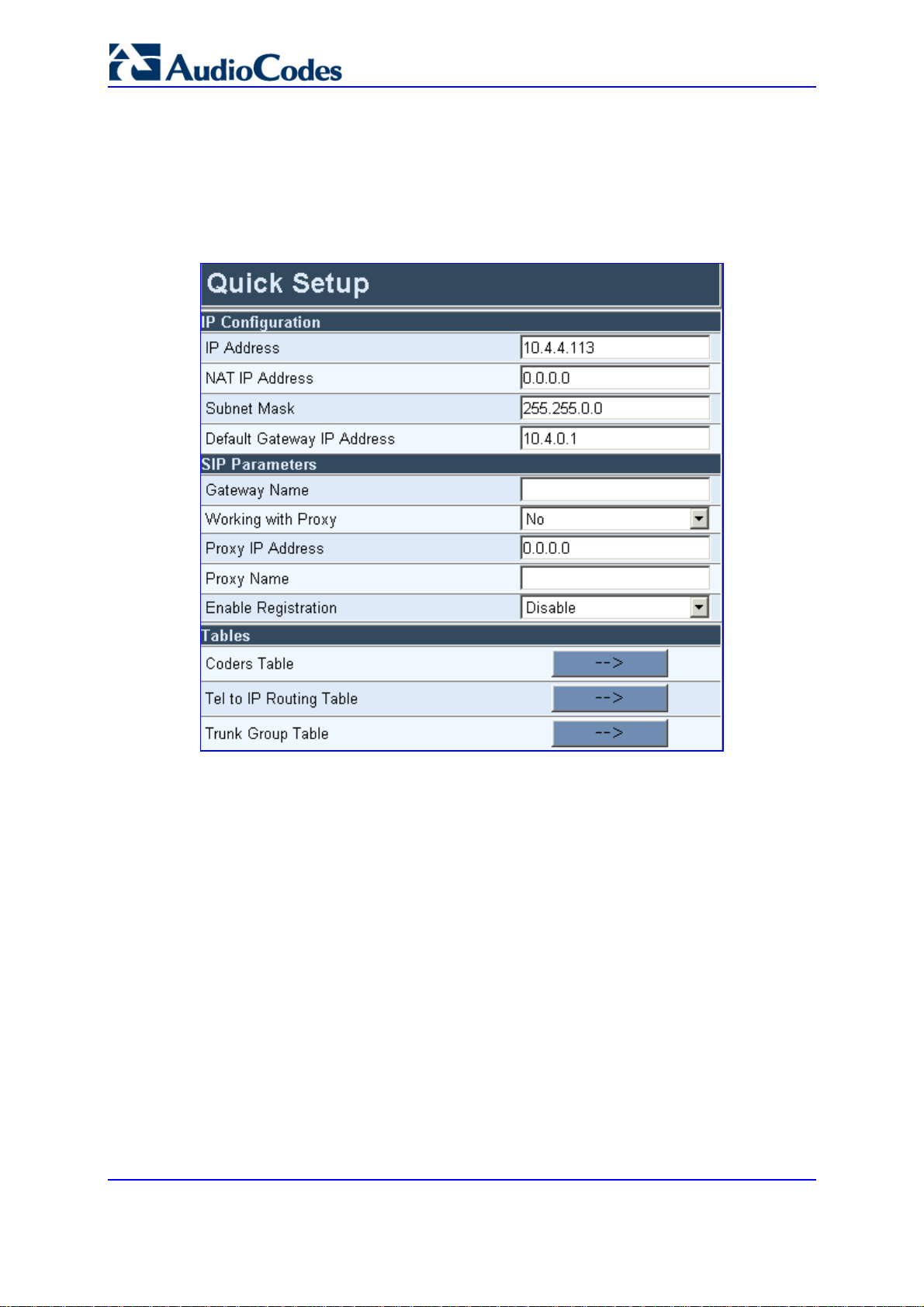
Mediant 2000 & TP-1610 & TP-260/UNI
4.4 Configuring Basic Parameters
To configure the gateway's basic parameters, use the Embedded Web Server’s ‘Quick
Setup’ screen (shown in the figure below). For information on accessing the Embedded
Web Server, refer to 'Accessing the Embedded Web Server' on page 60.
Figure 4-2: Quick Setup Screen
¾ To configure basic SIP parameters, take these 11 steps:
1. Access the ‘Quick Setup’ screen by clicking the Quick Setup menu.
2. If the gateway is connected to a router with NAT (Network Address Translation)
enabled, perform the following (if it isn’t, leave the ‘NAT IP Address’ field undefined):
• Determine the ‘public’ IP address assigned to the router (by using, for example,
router Web management). If the public IP address is static, enter this in the ‘NAT
IP Address’ field.
• Enable the DMZ (Demilitarized Zone) configuration on the router for the LAN port
where the gateway is connected. This enables unknown packets to be routed to
the DMZ port.
3. Under ‘SIP Parameters’, enter the gateway's domain name in the field ‘Gateway
Name’. If the field is not specified, the gateway's IP address is used instead (default).
4. When working with a Proxy server, set the ‘Working with Proxy’ field to ‘Yes’, and then
enter the IP address of the primary Proxy server in the field ‘Proxy IP address’. When
no Proxy is used, the internal routing table is used to route the calls.
SIP User's Manual 54 Document #: LTRT-68806
Page 55

SIP User's Manual 4. Getting Started
5. Enter the Proxy name in the field ‘Proxy Name’. If Proxy name is used, it replaces the
Proxy IP address in all SIP messages. This means that messages are still sent to the
physical Proxy IP address, but the SIP URI contains the Proxy name instead.
6. Configure ‘Enable Registration’ to either one of the following:
• ‘Disable’ = the gateway doesn't register to a Proxy server/Registrar (default).
• ‘Enable’ = the gateway registers to a Proxy server/Registrar at power up and
every ‘Registration Time’ seconds. For detailed information on the parameter
‘Registration Time’, refer to 'Proxy & Registration Parameters' on page 86.
7. To configure the Coders Table, click the arrow button next to ‘Coders Table’. For
information on how to configure the Coders Table, refer to 'Coders' on page 96.
8. To configure the Tel to IP Routing Table, click the arrow button next to ‘Tel to IP
Routing Table’. For information on how to configure the Tel to IP Routing Table, refer
to 'Tel to IP Routing Table' on page 122.
9. To configure the E1/T1 B-channels, click the arrow button next to ‘Trunk Group Table’.
For information on how to configure the Trunk Group Table, refer to Configuring the
Trunk Group Table on page 138.
10. Click the Reset button, and then at the prompt, click OK; the gateway applies the
changes and restarts.
11. After the gateway has reset, access the 'Trunk Settings' screen (Advanced
Configuration > Trunk Settings), and select the gateway's E1/T1 protocol type and
Framing method that best suits your system requirements. For information on how to
configure the Trunk Settings, refer to 'Trunk Settings' on page 178.
You are now ready to start configuring the gateway. To prevent unauthorized access to the
gateway, it's recommended that you change the default username and password used to
access the Embedded Web Server. Refer to 'Configuring the Web User Accounts' on page
197 on how to change the username and password.
Tip: Once the gateway is configured correctly, back up your settings by saving a
copy of the VoIP gateway configuration (ini file) to a directory on your PC.
This saved file can be used to restore configuration settings at a later date.
For information on backing up and restoring the gateway's configuration, refer
to 'Restoring and Backing up Configuration' on page 258.
Version 5.2 55 September 2007
Page 56

Mediant 2000 & TP-1610 & TP-260/UNI
Reader's Notes
SIP User's Manual 56 Document #: LTRT-68806
Page 57

SIP User's Manual 5. Web-based Management
5 Web-based Management
The gateway's Embedded Web Server is used for remote configuration of the gateway
including loading of configuration files, as well as for online monitoring of the gateway. In
addition, you can also remotely reset the gateway. The Embedded Web Server can be
accessed from a standard Web browser such as Microsoft™ Internet Explorer and
5.1 Computer Requirements
Netscape™ Navigator.
To use the gateway's Embedded Web Server, the following is required:
A computer capable of running your Web browser.
A network connection to the gateway's Embedded Web Server.
One of the following compatible Web browsers:
• Microsoft™ Internet Explorer™ (version 6.0 or later)
• Netscape™ Navigator™ (version 7.2 or later)
®
• Mozilla Firefox
(version 1.5.0.10 or later)
Note: The Web browser must be javascript-enabled. If javascript is disabled, access
to the Embedded Web Server is denied.
5.2 Protection and Security Mechanisms
Access to the gateway's Embedded Web Server is controlled by the following protection
and security mechanisms:
User accounts (refer to 'User Accounts' on page 58)
Read-only mode (refer to 'Limiting the Embedded Web Server to Read-Only Mode' on
page 59)
Disabling access (refer to 'Disabling the Embedded Web Server' on page 59)
Limiting access to a predefined list of IP addresses (refer to 'Configuring the Web and
Telnet Access List' on page 199)
Secured HTTP connection (HTTPS) (refer to the SIP Series Reference Manual)
Managed access using a RADIUS server (refer to the SIP Series Reference Manual)
Version 5.2 57 September 2007
Page 58

Mediant 2000 & TP-1610 & TP-260/UNI
5.2.1 User Accounts
Up to five simultaneous users can be handled on gateway authentication via the
Embedded Web Server. To prevent unauthorized access to the Embedded Web Server,
two user accounts are available: primary and secondary. Each account is composed of
three attributes: username, password, and access level. The username and password
enable access to the Embedded Web Server itself; the access level determines the extent
of the access (i.e., availability of screens and read / write privileges). Note that additional
accounts can be defined using a RADIUS server (refer to the SIP Series Reference
Manual).
The following table lists the available access levels and their privileges.
Table 5-1: Available Access Levels and their Privileges
Access Level
Security Administrator 200 Read / write privileges for all screens
Administrator 100
User Monitor 50
No Access 0 No access to any screen
* The numeric representation of the access level is used only to define accounts in a RADIUS server
(the access level ranges from 1 to 255).
Each Web screen features two (hard-coded) minimum access levels, read and write. The
read access level determines whether the screen can be viewed. The write access level
determines whether the information in the screen can be modified. When a user tries to
access a specific Web screen, the user's access level is compared with the access levels
of the screen:
If the access level of the user is less than the screen's read access level, the screen
cannot be viewed.
If the access level of the user is equal to or greater than the screen's read access level
but less than the write access level, the screen is read only.
Numeric
Representation*
Privileges
Read-only privilege for security-related screens
and read / write privileges for the others
No access to security-related and file-loading
screens and read-only access to the others
If the access level of the user is equal to or greater than the screen's write access
level, the screen can be modified.
The default attributes for the two accounts are shown in the following table:
Table 5-2: Default Attributes for the Accounts
Account / Attribute Username
(Case-Sensitive)
Primary Account Admin Admin Security Administrator*
Secondary Account User User User Monitor
* The access level of the primary account cannot be changed; all other account-attributes can be
modified.
SIP User's Manual 58 Document #: LTRT-68806
Password
(Case-Sensitive)
Access Level
Page 59

SIP User's Manual 5. Web-based Management
The first time a Web browser request is made, users are requested to provide their
account's username and password to obtain access. If the Embedded Web Server is left
idle for more than five minutes, the session expires and the user is required to re-enter
username and password.
Tip: To access the Embedded Web Server with a different account, click the Log
Off button and re-access with a new username and password.
For details on changing the account attributes, refer to 'Configuring the Web User
Accounts' on page 197. Note that the password and username can be a maximum of 19
case-sensitive characters.
To reset the username and password of both accounts to their defaults, set the ini file
parameter ResetWebPassword to 1.
5.2.2 Limiting the Embedded Web Server to Read-Only Mode
Users can limit access to the Embedded Web Server to read-only mode by changing the ini
file parameter DisableWebConfig to 1. In this mode, all Web screens, regardless of the
access level used, are read-only and cannot be modified. In addition, the following screens
cannot be accessed: 'Quick Setup', 'Web User Accounts', 'Maintenance Actions' and all fileloading screens.
Notes:
• Read-only policy can also be applied to selected users by setting the
access level of the secondary account to 'User Monitor'
(DisableWebConfig = 0) and distributing the primary and secondary
accounts to users according to the organization's security policy.
• When DisableWebConfig is set to 1, read-only privileges are applied to
all accounts regardless of their access level.
5.2.3 Disabling the Embedded Web Server
Access to the Embedded Web Server can be disabled by setting the ini file parameter
DisableWebTask to 1. By default, the access is enabled.
Version 5.2 59 September 2007
Page 60
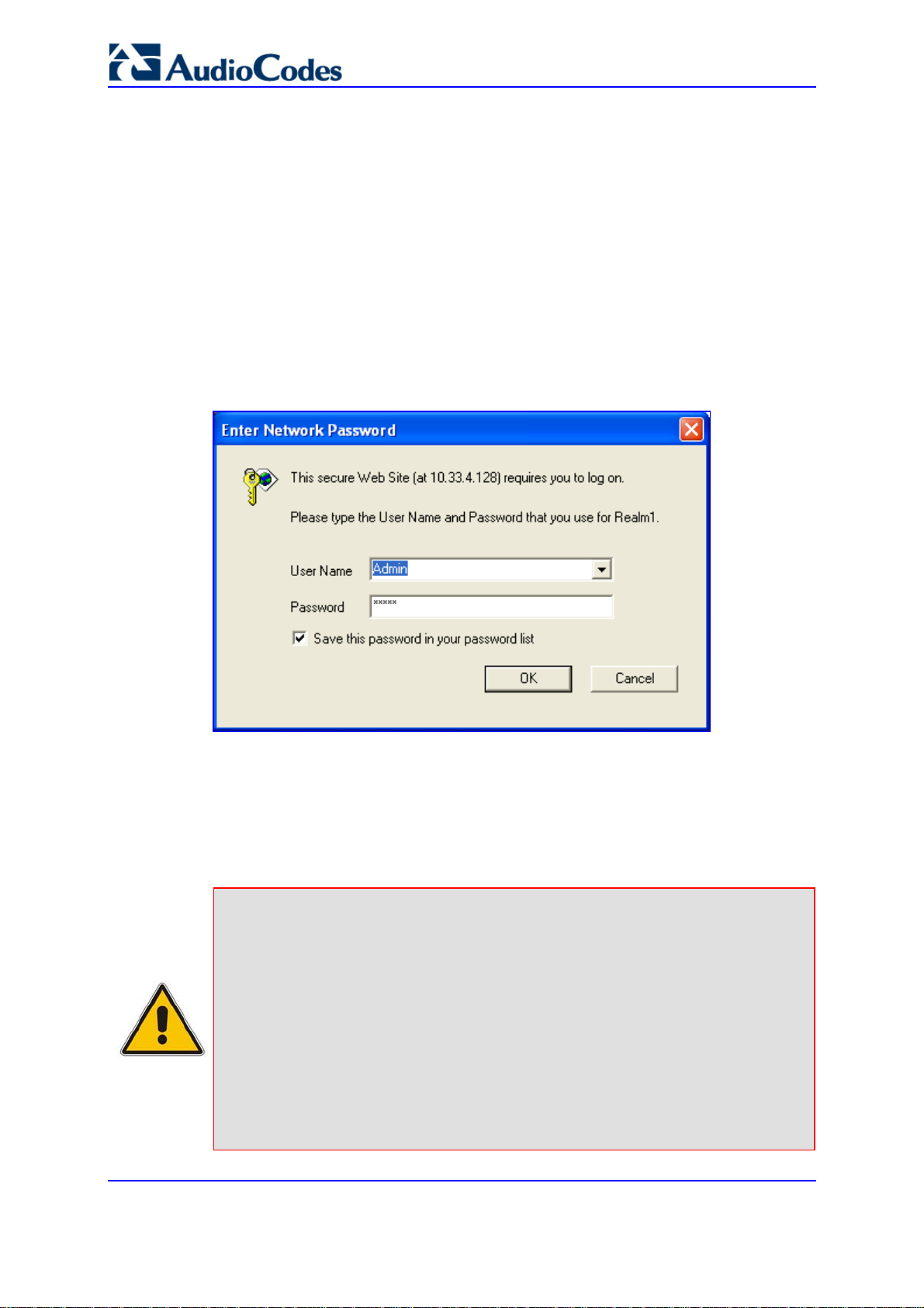
Mediant 2000 & TP-1610 & TP-260/UNI
5.3 Accessing the Embedded Web Server
You can access the gateway's Embedded Web Server by following the procedure below.
¾ To access the Embedded Web Server, take these 4 steps:
1. Open a standard Web-browsing application (for a list of supported Web browsers,
refer to 'Computer Requirements' on page 57).
2. In the Web browser's Uniform Resource Locator (URL) field, specify the gateway's IP
address (e.g., http://10.1.10.10); the Embedded Web Server's 'Enter Network
Password' screen appears, as shown in the figure below.
Figure 5-1: Enter Network Password Screen
3. In the 'User Name' and 'Password' fields, enter the username (default: 'Admin') and
password (default: 'Admin'). Note that the username and password are case-sensitive.
4. Click the OK button; the Embedded Web Server is accessed, displaying the Home
page (for a detailed description of the Home page, refer to Using the Home Page on
page 260).
Note: If access to the gateway's Embedded Web Server is denied ("Unauthorized")
due to Microsoft Internet Explorer security settings, perform the following
troubleshooting procedures:
1. Delete all cookies in the Temporary Internet Files folder. If this does not
resolve the problem, the security settings may need to be altered
(continue with Step 2).
2. In Internet Explorer, navigate to Tools menu > Internet Options >
Security tab > Custom Level, and then scroll down to the Logon options
and select Prompt for username and password. Select the Advanced
tab, and then scroll down until the HTTP 1.1 Settings are displayed and
verify that Use HTTP 1.1 is selected.
3. Quit and start the Web browser again.
SIP User's Manual 60 Document #: LTRT-68806
Page 61

SIP User's Manual 5. Web-based Management
5.4 Getting Acquainted with the Web Interface
The figure below displays the general layout of the interface of the Embedded Web Server.
The Embedded Web Server features the following components:
Title bar: contains three configurable elements: corporate logo, a background image,
and the product's name. For information on how to modify these elements, refer to
'Customizing the Web Interface' on page 65.
Main menu bar: contains the main menus (refer to 'Main Menu Bar' on page 62).
Submenu bar: contains submenus pertaining to the selected main menu (from the
Main menu bar). Each submenu provides a list of drop-down options that access
configuration screens.
Main action frame: main area of the Embedded Web Server in which configuration
screens are displayed.
Home icon: opens the Home page screen used mainly for monitoring the gateway
(refer to 'Using the Home Page' on page 260).
Corporate logo: AudioCodes' corporate logo. For information on how to remove this
logo, refer to 'Customizing the Web Interface' on page 65.
Search engine: used for searching ini file parameters that have corresponding
Embedded Web Server parameters (refer to 'Searching for Configuration Parameters'
on page 63).
Control Protocol: the gateway's control protocol (i.e., SIP).
Version 5.2 61 September 2007
Page 62

5.4.1 Main Menu Bar
The main menu bar of the Embedded Web Server provides the following menus:
Quick Setup: Accesses the 'Quick Setup' screen for quickly configuring the gateway's
basic settings.For a full list of configurable parameters, directly access the Protocol
Management and Advanced Configuration menus. An example of the Quick Setup
configuration is described in 'Configuring the Basic Parameters' on page 54.
Protocol Management: used to configure the gateway's control protocol parameters
and tables (refer to 'Protocol Management' on page 71).
Advanced Configura tion : used to configure the gateway's advanced configuration
parameters.
Status & Diagnostics: use to view Syslog messages, hardware / software product
information, and to assess the gateway's statistics and IP connectivity information
(refer to 'Status & Diagnostics' on page 226).
Soft ware Update: used to load new software or configuration files to the gateway
(refer to 'Software Update' on page 240).
Maintenance: used to remotely lock/unlock the gateway (refer to 'Locking and
Unlocking the Gateway' on page 254), save configuration changes to the non-volatile
flash memory (refer to 'Saving Configuration' on page 256), and reset the gateway
(refer to 'Resetting the Gateway' on page 257).
Mediant 2000 & TP-1610 & TP-260/UNI
5.4.2 Saving Changes
To apply changes to the gateway's volatile memory (RAM), click the Submit button that
appears in the screen in which you are working. Modifications to parameters with on-the-fly
capabilities are immediately applied to the gateway; other parameters are updated only
after a gateway reset.
Parameters saved to the volatile memory (i.e., not burned to flash memory), revert to their
previous settings after a hardware reset (or if the gateway is powered down). However,
when performing a software reset (i.e., using the Embedded Web Server or SNMP), you
can also choose to save the parameter settings to the non-volatile memory (i.e., flash). To
save the changes to flash, refer to 'Saving Configuration' on page 256.
Note: Parameters preceded by an exclamation mark (!) are not changeable on-the-
fly and require that the device be reset.
5.4.3 Entering Phone Numbers in Various Tables
Phone numbers or prefixes entered into various tables on the gateway such as the Tel to
IP routing table, must be entered without any formatting characters. For example, if you
wish to enter the phone number 555-1212, it must be entered as 5551212 without the
hyphen (-). If the hyphen is entered, the entry is not valid. The hyphen character is used in
number entry only, as part of a range definition. For example, the entry [20-29] means 'all
numbers in the range 20 to 29.
SIP User's Manual 62 Document #: LTRT-68806
Page 63

SIP User's Manual 5. Web-based Management
5.4.4 Searching for Configuration Parameters
The Embedded Web Server provides a search engine that allows you to search any ini file
parameter that is configurable by the Web server. The Search button, located near the
bottom of the Main menu bar is used to perform parameter searches.
You can search for a specific parameter (e.g., "EnableIPSec") or a sub-string of that
parameter (e.g., "sec"). If you search for a sub-string, the Embedded Web Server lists all
parameters that contain the searched sub-string in their parameter names.
¾ To search for ini file parameters configurable in the Embedded
Web Server, take these 3 steps:
1. In the Search Engine field, enter the parameter name or sub-string of the parameter
name.
2. Click Search. The Searched Result screen appears, listing all searched parameter
results, as shown in the example below:
Figure 5-2: Searched Result Screen
Each searched result displays the following:
• Parameter name (hyperlinked to its location in the Embedded Web Server)
• Brief description of the parameter
• Hyperlink in green displaying the URL path to its location in the Embedded Web
Server location
Version 5.2 63 September 2007
Page 64
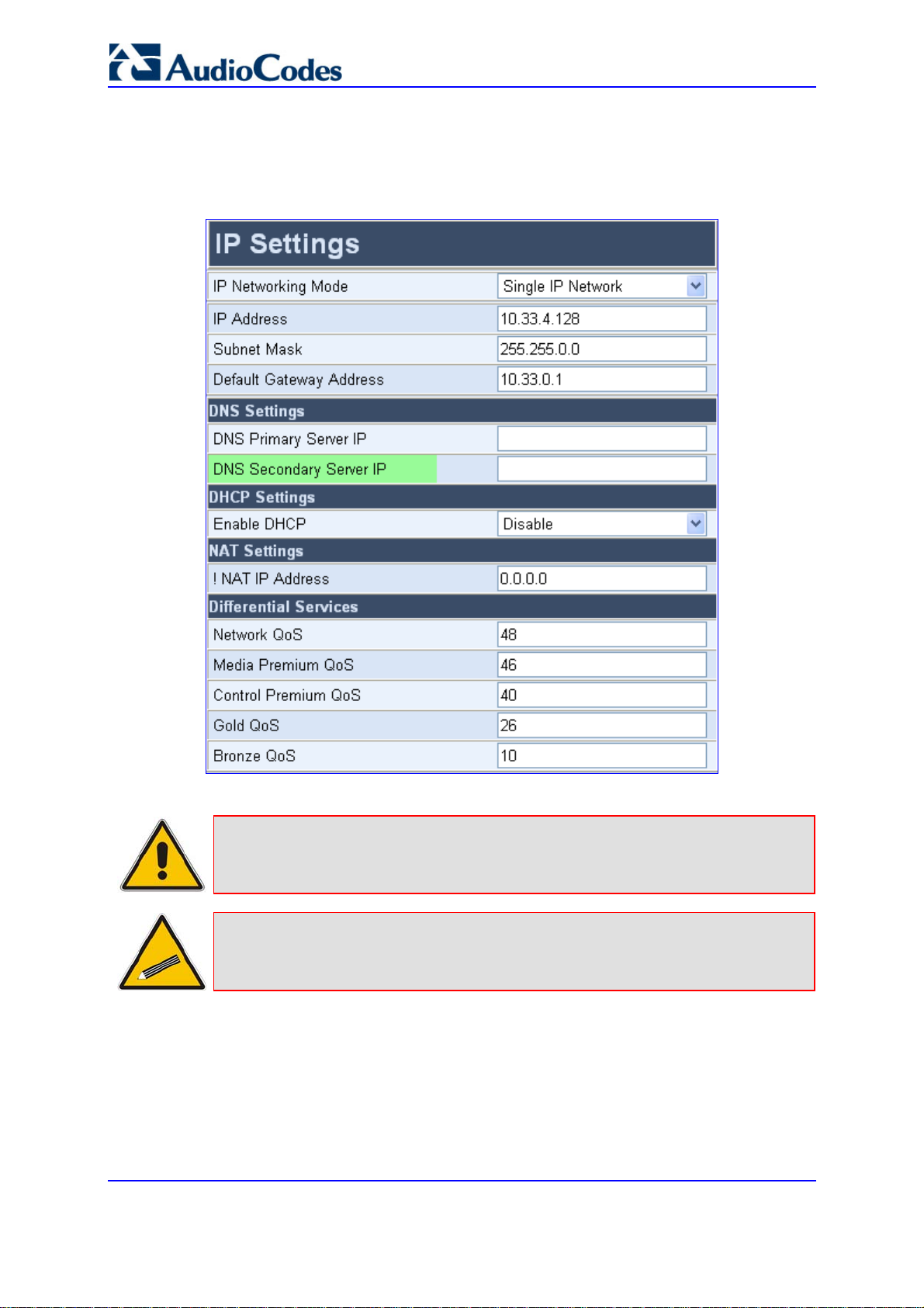
Mediant 2000 & TP-1610 & TP-260/UNI
3. In the searched result list, click the required parameter to open the screen in which the
parameter appears; the searched parameter is highlighted in green in the screen for
easy identification, as shown in the figure below.
Figure 5-3: Searched Parameter Highlighted in Screen
Note: If the searched parameter is not located, the "No Matches Found For This
String" message is displayed.
Tip: When moving your curser over a parameter name (or table) for more than a
second, a short description of the parameter is briefly displayed.
SIP User's Manual 64 Document #: LTRT-68806
Page 65

SIP User's Manual 5. Web-based Management
5.4.5 Customizing the Web Interface
You can customize the gateway's Embedded Web Server interface to suit your specific
corporate logo and product naming conventions. The following Web interface elements can
be customized:
Main corporate logo displayed on the title bar (refer to 'Replacing the Main Corporate
Logo' on page 65)
Background image displayed on the title bar (refer to 'Replacing the Background
Image File' on page 68)
Product’s name displayed on the title bar (refer to 'Customizing the Product Name' on
page 69)
Login welcome message (refer to 'Creating a Login Welcome Message' on page 70)
The figure below displays an example of the default title bar (i.e., of AudioCodes) and
below it, a customized one:
Figure 5-4: Customized Web Interface Title Bar
Figure 5-5: Customized Web Interface Title Bar
5.4.5.1 Replacing the Main Corporate Logo
The main corporate logo can be replaced either with a different logo image file (refer to
'Replacing the Main Corporate Logo with an Image File' on page 66) or with a text string
(refer to 'Replacing the Main Corporate Logo with a Text String' on page 67).
Notes:
• When the main corporation logo is replaced, AudioCodes’ logo on the left
bar (refer to 'Getting Acquainted with the Web Interface' on page 61) and
in the Software Upgrade Wizard (refer to 'Software Upgrade Wizard' on
page 240) disappear.
• The Web browser’s title bar is automatically updated with the string
assigned to the WebLogoText parameter when AudioCodes’ default logo
is not used.
Version 5.2 65 September 2007
Page 66
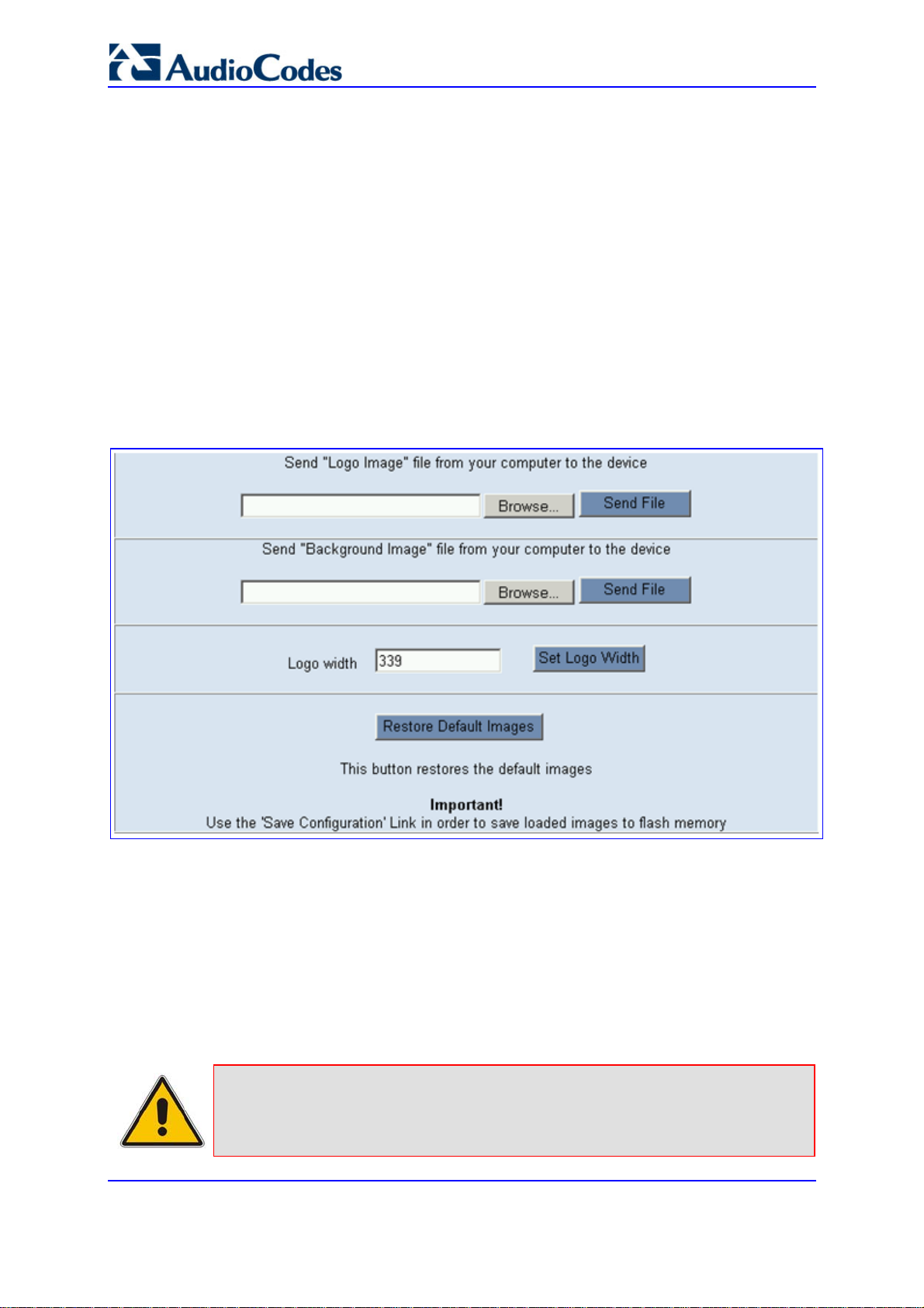
Mediant 2000 & TP-1610 & TP-260/UNI
5.4.5.1.1 Replacing the Main Corporate Logo with an Image File
You can replace the logo in the Web interface's title bar using either the Embedded Web
Server or the ini file.
¾ To replace the default logo with your own corporate image via the
Embedded Web Server, take these 7 steps:
1. Access the gateway's Embedded Web Server (refer to 'Accessing the Embedded Web
Server' on page 60).
2. In the URL field, append the case-sensitive suffix ‘AdminPage’ to the IP address (e.g.,
http://10.1.229.17/AdminPage).
3. Click Image Load to Device; the Image Download screen is displayed, as shown in
the figure below.
Figure 5-6: Image Download Screen
4. Click the Browse button in the 'Send Logo Image File from your computer to the
Device' box. Navigate to the folder that contains the logo image file you want to load.
5. Click the Send File button; the file is sent to the device. When loading is complete, the
screen is automatically refreshed and the new logo image is displayed.
6. If you want to modify the width of the logo (the default width is 339 pixels), in the 'Logo
Width' field, enter the new width (in pixels) and then click the Set Logo Width button.
7. To save the image to flash memory, refer to 'Saving Configuration' on page 256.
The new logo appears on all Embedded Web Server interface pages.
Note: Use a gif, jpg or jpeg file for the logo image. It is important that the image file
has a fixed height of 59 pixels (the width can be configured up to a maximum
of 339 pixels). The size of the image files (logo and background) is limited
SIP User's Manual 66 Document #: LTRT-68806
each to 64 Kbytes.
Page 67

SIP User's Manual 5. Web-based Management
Tip: If you encounter any problem during the loading of the files or you want to
restore the default images, click the Restore Default Images button.
¾ To replace the default logo with your own corporate image via the
ini file, take these 3 steps:
1. Place your corporate logo image file in the same folder as where the device’s ini file is
located (i.e., the same location defined in the BootP/TFTP configuration utility). For
detailed information on the BootP/TFTP, refer to the SIP Series Reference Manual).
2. Add or modify the ini file parameters described in the table below (as described in'
Modifying an ini File' on page 267).
3. Load the ini file using only BootP / TFTP (i.e., not through the Embedded Web
Server).
Table 5-3: Customizable Logo ini File Parameters
Parameter Description
LogoFileName
The name of the image file containing your corporate logo. Use a gif, jpg or
jpeg image file.
The default is AudioCodes’ logo file.
Note: The length of the name of the image file is limited to 47 characters.
LogoWidth
Width (in pixels) of the logo image.
The default value is 339 (which is the width of AudioCodes’ displayed
logo).
Note: The optimal setting depends on the resolution settings.
5.4.5.1.2 Replacing the Main Corporate Logo with a Text String
The main corporate logo can be replaced with a text string. To replace AudioCodes’ default
logo with a text string using the ini file, add or modify the two ini file parameters listed in the
table below (according to the procedure described in n 'Modifying an ini File' on page 267).
Table 5-4: Web Appearance Customizable ini File Parameters
Parameter Description
UseWebLogo
[0] = Logo image is used (default).
[1] = Text string is used instead of a logo image.
WebLogoText
Text string that replaces the logo image.
The string can be up to 15 characters.
Version 5.2 67 September 2007
Page 68

Mediant 2000 & TP-1610 & TP-260/UNI
5.4.5.2 Replacing the Background Image File
The background image file is duplicated across the width of the screen. The number of
times the image is duplicated depends on the width of the background image and screen
resolution. When choosing your background image, keep this in mind. The background
image file can be replaced using either the Embedded Web Server or the ini file.
Note: Use a gif, jpg or jpeg file for the background image. It is important that the
image file has a fixed height of 59 pixels. The size of the image files (logo and
background) is limited each to 64 Kbytes.
¾ To replace the background image using the Embedded Web
Server, take these 6 steps:
1. Access the gateway's Embedded Web Server (refer to 'Accessing the Embedded Web
Server' on page 60).
2. In the Web browser's URL field, append the case-sensitive suffix ‘AdminPage’ to the
IP address (e.g., http://10.1.229.17/AdminPage).
3. Click the Image Load to Device; the 'Image Download' screen is displayed (shown in'
Replacing the Main Corporate Logo with an Image File' on page 66).
4. Click the Browse button in the 'Send Background Image File from your computer to
box', and then navigate to the folder that contains the background image file you want
to load.
5. Click the Send File button; the file is sent to the device. When loading is complete, the
screen is automatically refreshed and the new background image is displayed.
6. To save the image to flash memory, refer to 'Saving Configuration' on page 256.
The new background appears on all Embedded Web Server interface pages.
Tips:
• If you encounter any problem during the loading of the files or you want
to restore the default images, click the Restore Default Images button.
• When replacing both the background image and the logo image, first load
the logo image followed by the background image.
SIP User's Manual 68 Document #: LTRT-68806
Page 69

SIP User's Manual 5. Web-based Management
¾ To replace the background image via the ini file, take these 3
steps:
1. Place your background image file in the same folder as where the device’s ini file is
located (i.e., the same location defined in the BootP/TFTP configuration utility). For
detailed information on the BootP/TFTP, refer to the SIP Series Reference Manual).
2. Add or modify the ini file parameters listed in the table below (according to the
procedure described in 'Modifying an ini File' on page 267).
3. Load the ini file using only BootP / TFTP (i.e., not through the Embedded Web
Server).
Table 5-5: Customizable Logo ini File Parameters
Parameter Description
BkgImageFileName
The name (and path) of the file containing the new background.
Use a gif, jpg or jpeg image file.
The default is AudioCodes background file.
Note: The length of the name of the image file is limited to 47 characters.
5.4.5.3 Customizing the Product Name
To replace AudioCodes’ default product name with a text string, add or modify the two ini
file parameters listed in the table below (according to the procedure described in' Modifying
an ini File' on page 267).
Table 5-6: Web Appearance Customizable ini File Parameters
Parameter Description
UseProductName
UserProductName
[0] = Don’t change the product name (default).
[1] = Enable product name change.
Text string that replaces the product name.
The default is ‘Mediant 2000’.
The string can be up to 29 characters.
Version 5.2 69 September 2007
Page 70

Mediant 2000 & TP-1610 & TP-260/UNI
5.4.5.4 Creating a Login Welcome Message
You can create a Welcome message box (alert message) that appears (see figure below for an
example) after each successful login to the gateway's Embedded Web Server. The ini file parameter
table WelcomeMessage allows you to create the Welcome message. Up to 20 lines of character
strings can be defined for the message. If this parameter is not configured, no Welcome message box
is displayed after login.
Figure 5-7: User-Defined Web Welcome Message after Login
Parameter Description
WelcomeMessage
Table 5-7: User-Defined Welcome Message ini File Parameter
Configures the Welcome message that appears after a Embedded Web
Server login.
The format of this ini file parameter table is:
[WelcomeMessage]
FORMAT WelcomeMessage_Index = WelcomeMessage_Text
WelcomeMessage 1 = "..." ;
WelcomeMessage 2 = "..." ;
WelcomeMessage 3 = "..." ;
[\WelcomeMessage]
For Example:
[WelcomeMessage ]
FORMAT WelcomeMessage_Index = WelcomeMessage_Text
WelcomeMessage 1 = "**********************************" ;
WelcomeMessage 2 = "********* This is a Welcome message ***" ;
WelcomeMessage 3 = "**********************************" ;
[\WelcomeMessage]
Note: Each index represents a line of text in the Welcome message box.
Up to 20 indexes can be defined.
SIP User's Manual 70 Document #: LTRT-68806
Page 71

SIP User's Manual 5. Web-based Management
5.5 Protocol Management
The Protocol Management menu is used to configure the gateway's SIP parameters and
tables.
Note: Throughout this section, parameters enclosed in square brackets ([...]) depict
the ini file parameters that correspond to the Embedded Web Server
parameters. For configuration using the ini file, refer to 'ini File Configuration'
5.5.1 Protocol Definition Parameters
The Protocol Definition submenu is used to configure the following SIP protocol
parameters:
General (refer to 'General Parameters' on page 72)
Proxy & Registration (refer to 'Proxy & Registration Parameters' on page 86)
on page 267.
Coders (refer to 'Coders' on page 96)
DTMF & Dialing (refer to 'DTMF & Dialing Parameters' on page 99)
Version 5.2 71 September 2007
Page 72

Mediant 2000 & TP-1610 & TP-260/UNI
5.5.1.1 General Parameters
The General Parameters option is used to configure general SIP parameters.
¾ To configure the general SIP protocol parameters, take these 4
steps:
1. Open the 'General Parameters' screen (Protocol Management menu > Protocol
Definition submenu > General Parameters option).
Figure 5-8: General Parameters (Protocol Definition Submenu)
SIP User's Manual 72 Document #: LTRT-68806
Page 73

SIP User's Manual 5. Web-based Management
2. Configure the parameters according to the table below.
3. Click the Submit button to save your changes.
4. To save the changes to flash memory, refer to 'Saving Configuration' on page 256.
Table 5-8: General Parameters (Protocol Definition)
Parameter Description
PRACK Mode
[PRACKMode]
PRACK mechanism mode for 1xx reliable responses.
Valid options include:
[0] Disable
[1] Supported (default)
[2] Required
Notes:
The Supported and Required headers contain the '100rel'
parameter.
The gateway sends PRACK message if 180/183 response
is received with '100rel' in the Supported or the Required
headers.
Version 5.2 73 September 2007
Page 74

Mediant 2000 & TP-1610 & TP-260/UNI
Table 5-8: General Parameters (Protocol Definition)
Parameter Description
Channel Select Mode
[ChannelSelectMode]
Port allocation algorithm for IP-to-Tel calls.
You can select one of the following methods:
[0] By Dest Phone Number = (default) Select the gateway
port according to the called number.
[1] Cyclic Ascending = Select the next available channel
in an ascending cycle order. Always select the next higher
channel number in the trunk group. When the gateway
reaches the highest channel number in the trunkgroup, it
selects the lowest channel number in the trunkgroup and
then starts ascending again.
[2] Ascending = Select the lowest available channel.
Always start at the lowest channel number in the trunk
group and if that channel is not available, select the next
higher channel.
[3] Cyclic Descending = Select the next available channel
in descending cycle order. Always select the next lower
channel number in the trunk group. When the gateway
reaches the lowest channel number in the hunt group, it
selects the highest channel number in the trunk group and
then starts descending again.
[4] Descending = Select the highest available channel.
Always start at the highest channel number in the trunk
group and if that channel is not available, select the next
lower channel.
[5] Dest Number + Cyclic Ascending = First select the
gateway port according to the called number. If the called
number isn't found, then select the next available channel
in ascending cyclic order. Note that if the called number is
found, but the port associated with this number is busy,
the call is released.
[6] By Source Phone Number = Select the gateway port
according to the calling number.
[7] Trunk Cyclic Ascending = Select the gateway port from
the first channel of the next trunk (next to the trunk from
which the previous channel was allocated.
Note: The internal numbers of the gateway's B-channels are
defined by the TrunkGroup parameter.
Enable Early Media
[EnableEarlyMedia]
If enabled, the gateway sends 183 Session Progress
response with SDP (instead of 180 Ringing), allowing the
media stream to be set up prior to the answering of the call.
[0] Disable = Early Media is disabled (default).
[1] Enable = Enables Early Media.
Sending a 183 response depends on the Progress Indicator.
It is sent only if PI = 1 or PI = 8 is received in Proceeding or
Alert PRI messages. For CAS gateways, see the
ProgressIndicator2IP parameter.
SIP User's Manual 74 Document #: LTRT-68806
Page 75

SIP User's Manual 5. Web-based Management
Table 5-8: General Parameters (Protocol Definition)
Parameter Description
183 Message Behavior
[SIP183Behavior]
Session-Expires Time
[SIPSessionExpires]
Minimum Session-Expires
[MINSE]
Session Expires Method
[SessionExpiresMethod]
Asserted Identity Mode
[AssertedIdMode]
Defines the ISDN message that is sent when 183 Session
Progress message is received for IP-to-Tel calls.
Valid options include:
[0] Progress = Progress message (default).
[1] Alert = Alert message.
When set to 1, the gateway sends an Alert message (after
the receipt of a 183 response) instead of an ISDN Progress
message.
Determines the timeout (in seconds) for keeping a Re-INVITE
message alive within a SIP session. The SIP session is
refreshed each time this timer expires. The SIP method used
for session-timer updates is determined according to the
parameter SessionExpiresMethod.
The valid range is 1 to 86400 sec. The default is 0 (i.e., not
activated).
Defines the time (in seconds) that is used in the Min-SE
header. This header defines the minimum time that the user
agent supports for session refresh.
The valid range is 10 to 100000. The default value is 90.
Defines the SIP method used for session-timer updates.
Valid options include:
[0] Re-Invite = Use Re-INVITE messages for session-
timer updates (default).
[1] Update = Use UPDATE messages.
Notes:
The gateway can receive session-timer refreshes using
both methods.
The UPDATE message used for session-timer purposes is
excluded from the SDP body.
[0] Disabled = None (default)
[1] Adding PAsserted Identity
[2] Adding PPreferred Identity
The Asserted ID mode defines the header that is used in the
generated INVITE request. The header also depends on the
calling Privacy: allowed or restricted.
The P-asserted (or P-preferred) headers are used to present
the originating party's Caller ID. The Caller ID is composed of
a Calling Number and (optionally) a Calling Name.
P-asserted (or P-preferred) headers are used together with
the Privacy header. If Caller ID is restricted, the 'Privacy: id' is
included. Otherwise for allowed Caller ID, the 'Privacy: none'
is used. If Caller ID is restricted (received from PSTN), the
From header is set to <anonymous@anonymous.invalid>.
Version 5.2 75 September 2007
Page 76

Mediant 2000 & TP-1610 & TP-260/UNI
Table 5-8: General Parameters (Protocol Definition)
Parameter Description
Fax Signaling Method
[IsFaxUsed]
Detect Fax on Answer Tone
[DetFaxOnAnswerTone]
Determines the SIP signaling method used to establish and
convey a fax session after a fax is detected.
[0] No Fax = No fax negotiation using SIP signaling. Fax
transport method is according to the parameter
FaxTransportMode (default).
[1] T.38 Relay = Initiates T.38 fax relay.
[2] G.711 Transport = Initiates fax / modem using the
coder G.711 A-law/µ-law with adaptations (refer to Note
below).
[3] Fax Fallback = Initiates T.38 fax relay. If the T.38
negotiation fails, the gateway re-initiates a fax session
using the coder G.711 A-law/µ-law with adaptations (refer
to Note below).
Notes:
Fax adaptations (for options 2 and 3):
Echo Canceller = On
Silence Compression = Off
Echo Canceller Non-Linear Processor Mode = Off
Dynamic Jitter Buffer Minimum Delay = 40
Dynamic Jitter Buffer Optimization Factor = 13
If the gateway initiates a fax session using G.711 (option 2
and possibly 3), a 'gpmd' attribute is added to the SDP in
the following format: For A-law: 'a=gpmd:0
vbd=yes;ecan=on'.
For µ-law: 'a=gpmd:8 vbd=yes;ecan=on'.
When IsFaxUsed is set to 1, 2, or 3 the parameter
FaxTransportMode is ignored.
When the value of IsFaxUsed is other than 1, T.38 might
still be used without the control protocol's involvement. To
completely disable T.38, set FaxTransportMode to a value
other than 1.
For detailed information on fax transport methods, refer to
'Fax/Modem Transport Modes' on page 341.
[0] Initiate T.38 on Preamble = Terminating fax gateway
initiates T.38 session on receiving V.21 preamble signal
from fax (default)
[1] Initiate T.38 on CED = Terminating fax gateway
initiates T.38 session on receiving CED answer tone from
fax.
Note: This parameters is applicable only if IsFaxUsed = 1.
SIP User's Manual 76 Document #: LTRT-68806
Page 77

SIP User's Manual 5. Web-based Management
Table 5-8: General Parameters (Protocol Definition)
Parameter Description
SIP Transport Type
[SIPTransportType]
SIP UDP Local Port
[LocalSIPPort]
SIP TCP Local Port
[TCPLocalSIPPort]
SIP TLS Local Port
[TLSLocalSIPPort]
Enable SIPS
[EnableSIPS]
Determines the default transport layer used for outgoing SIP
calls initiated by the gateway.
Valid options include:
[0] UDP (default)
[1] TCP
[2] TLS (SIPS)
Note: It's recommended to use TLS to communicate with a
SIP Proxy and not for direct gateway-gateway
communication.
Local UDP port used to receive SIP messages.
The valid range is 1 to 65534. The default value is 5060.
Local TCP port used to receive SIP messages.
The default value is 5060.
Local TLS port used to receive SIP messages.
The default value is 5061.
Note: The value of TLSLocalSIPPort must be different to the
value of TCPLocalSIPPort.
Enables secured SIP (SIPS) connections over multiple hops.
[0] Disable (default).
[1] Enable.
When SIPTransportType = 2 (TLS) and EnableSIPS is
disabled, TLS is used for the next network hop only. When
SIPTransportType = 2 (TLS) or 1 (TCP) and EnableSIPS is
enabled, TLS is used through the entire connection (over
multiple hops).
Note: If SIPS is enabled and SIPTransportType = UDP, the
connection fails.
Enable TCP Connection Reuse
[EnableTCPConnectionReuse]
Enables the reuse of the same TCP connection for all calls to
the same destination.
Valid options include:
[0] Disable = Use a separate TCP connection for each call
(default)
[1] Enable = Use the same TCP connection for all calls
TCP Timeout
[SIPTCPTimeout]
Defines the Timer B and Timer F (as defined in RFC 3261)
when the SIP Transport Type is TCP.
The valid range is 0 to 40 sec. The default value is SIPT1Rtx
* 64 msec.
SIP Destination Port
[SIPDestinationPort]
SIP destination port for sending initial SIP requests.
The valid range is 1 to 65534. The default port is 5060.
Note: SIP responses are sent to the port specified in the Via
header.
Use “user=phone” in SIP URL
[IsUserPhone]
[0] No = 'user=phone' string isn't used in SIP URI.
[1] Yes = 'user=phone' string is part of the SIP URI
(default).
Version 5.2 77 September 2007
Page 78

A
Mediant 2000 & TP-1610 & TP-260/UNI
Table 5-8: General Parameters (Protocol Definition)
Parameter Description
Use “user=phone” in From Header
[IsUserPhoneInFrom]
Use Tel URI for Asserted Identity
[UseTelURIForAssertedID]
Tel to IP No Answer Timeout
[IPAlertTimeout]
Enable Remote Party ID
[EnableRPIheader]
dd Number Plan and Type to Remote
Party ID Header
[AddTON2RPI]
[0] No = Doesn't use ';user=phone' string in From header
(default).
[1] Yes = ';user=phone' string is part of the From header.
Determines the format of the URI in the P-Asserted and PPreferred headers.
[0] Disable = 'sip:' (default).
[1] Enable = 'tel:'.
Defines the time (in seconds) the gateway waits for a 200 OK
response from the called party (IP side) after sending an
INVITE message. If the timer expires, the call is released.
The valid range is 0 to 3600. The default value is 180.
Enable Remote-Party-ID (RPI) headers for calling and called
numbers for TelÆIP calls.
Valid options include:
[0] Disable (default).
[1] Enable = RPI headers are generated in SIP INVITE
messages for both called and calling numbers.
[0] No = TON/PLAN parameters aren't included in the
RPID header.
[1] Yes = TON/PLAN parameters are included in the RPID
header (default).
If RPID header is enabled (EnableRPIHeader = 1) and
AddTON2RPI = 1, it's possible to configure the calling and
called number type and number plan using the Number
Manipulation tables for TelIP calls.
SIP User's Manual 78 Document #: LTRT-68806
Page 79

SIP User's Manual 5. Web-based Management
Table 5-8: General Parameters (Protocol Definition)
Parameter Description
Enable History-Info Header
[EnableHistoryInfo]
Enables usage of the History-Info header.
Valid options include:
[0] Disable = Disable (default)
[1] Enable = Enable
UAC Behavior:
Initial request: The History-Info header is equal to the
Request URI. If a PSTN Redirect number is received, it is
added as an additional History-Info header with an
appropriate reason.
Upon receiving the final failure response, the gateway
copies the History-Info as is, adds the reason of the failure
response to the last entry, and concatenates a new
destination to it (if an additional request is sent).
The order of the reasons is as follows:
- Q.850 Reason
- SIP Reason
- SIP Response code
Upon receiving the final (success or failure) response, the
gateway searches for a Redirect reason in the History-Info
(i.e., 3xx/4xx SIP Reason). If found, it is passed to ISDN,
according to the following table:
SIP Reason Code ISDN Redirecting Reason
302 - Moved Temporarily Call Forward Universal (CFU)
408 - Request Timeout
480 - Temporarily Unavailable
486 - Busy Here
600 - Busy Everywhere
Call Forward No Answer (CFNA)
Call Forward Busy (CFB)
If history reason is a Q.850 reason, it is translated to the
SIP reason (according to the SIP-ISDN tables) and then to
ISDN Redirect reason according to the table above.
UAS Behavior:
History-Info is sent in the final response only.
Upon receiving a request with History-Info, the UAS
checks the policy in the request. If 'session', 'header', or
'history' policy tag is found, the (final) response is sent
without History-Info. Otherwise, it is copied from the
request.
Version 5.2 79 September 2007
Page 80

Mediant 2000 & TP-1610 & TP-260/UNI
Table 5-8: General Parameters (Protocol Definition)
Parameter Description
Use Source Number as Display Name
[UseSourceNumberAsDisplayName]
Use Display Name as Source Number
[UseDisplayNameAsSourceNumber]
Applicable to Tel-to-IP calls.
[0] No = The Tel Source Number is used as the IP Source
Number and the Tel Display Name is used as the IP
Display Name (if Tel Display Name is received). If no
Display Name is received from the Tel side, the IP Display
Name remains empty (default).
[1] Yes = If a Tel Display Name is received, the Tel
Source Number is used as the IP Source Number and the
Tel Display Name is used as the IP Display Name. If no
Display Name is received from the Tel side, the Tel
Source Number is used as the IP Source Number and
also as the IP Display Name.
[2] Overwrite = The Tel Source Number is used as the IP
Source Number and also as the IP Display Name (even if
the received Tel Display Name is not empty).
Applicable to IP-to-Tel calls.
[0] No = The IP Source Number is used as the Tel Source
Number and the IP Display Name is used as the Tel
Display Name (if IP Display Name is received). If no
Display Name is received from IP, the Tel Display Name
remains empty (default).
[1] Yes = If an IP Display Name is received, it is used as
the Tel Source Number and also as the Tel Display Name,
the Presentation is set to Allowed (0). If no Display Name
is received from IP, the IP Source Number is used as the
Tel Source Number and the Presentation is set to
Restricted (1).
For example: When the following is received 'from: 100
<sip:200@201.202.203.204>', the outgoing Source Number
and Display Name are set to '100' and the Presentation is set
to Allowed (0).
When the following is received 'from:
<sip:100@101.102.103.104>', the outgoing Source Number
is set to '100' and the Presentation is set to Restricted (1).
SIP User's Manual 80 Document #: LTRT-68806
Page 81

SIP User's Manual 5. Web-based Management
Table 5-8: General Parameters (Protocol Definition)
Parameter Description
Play Ringback Tone to IP
[PlayRBTone2IP]
[0] Don't Play = Ringback tone isn't played to the IP side
of the call (default).
[1] Play = Ringback tone is played to the IP side of the call
after SIP 183 session progress response is sent.
If configured to 1 ('Play'), and if EnableEarlyMedia = 1, for IPto-Tel calls the gateway may play a ringback tone to IP,
according to the following:
For CAS interfaces, the gateway opens a voice channel,
sends a 183+SDP response and plays a Ringback tone to
IP.
For ISDN interfaces, if a Progress or an Alert message
with PI (1 or 8) is received from the ISDN, the gateway
opens a voice channel, sends a 183+SDP or 180+SDP
response, but it doesn't play a Ringback tone to IP. If PI (1
or 8) is received from the ISDN, the gateway assumes that
Ringback tone is played by the ISDN Switch. Otherwise,
the fateway plays a Ringback tone to IP after receiving an
Alert message from the ISDN. It sends a 180+SDP
response, signaling to the originating party to open a voice
channel to hear the played Ringback tone.
Notes:
To enable the gateway to send a 183/180+SDP
responses, set EnableEarlyMedia to 1.
If EnableDigitDelivery = 1, the gateway doesn't play a
Ringback tone to IP and doesn't send 183 or 180+SDP
responses.
Play Ringback Tone to Tel
[PlayRBTone2Tel]
Use Tgrp Information
[UseSIPTgrp]
Determines the method used to play Ringback tone to the Tel
side. It applies to all trunks that are not configured by the
parameter PlayRBTone2Trunk. Similar description as the
parameter PlayRBTone2Trunk.
[0] Disable = Tgrp parameter isn't used (default).
[1] Send Only = The trunk group number is added as the
'tgrp' parameter to the Contact header of outgoing SIP
messages. If a trunk group number is not associated with
the call, the 'tgrp' parameter isn't included. If a 'tgrp' value
is specified in incoming messages, it is ignored.
[2] Send and Receive = The functionality of outgoing SIP
messages is identical to the functionality described in
option (1). In addition, for incoming SIP messages, if the
Request-URI includes a 'tgrp' parameter, the gateway
routes the call according to that value (if possible). If the
Contact header includes a 'tgrp' parameter, it is copied to
the corresponding outgoing messages in that dialog.
Version 5.2 81 September 2007
Page 82

Mediant 2000 & TP-1610 & TP-260/UNI
Table 5-8: General Parameters (Protocol Definition)
Parameter Description
Enable GRUU
[EnableGRUU]
Determines whether or not the Globally Routable User Agent
URIs (GRUU) mechanism is used.
Valid options include:
[0] Disable = Disable (default)
[1] Enable = Enable
The gateway obtains a GRUU by generating a normal
REGISTER request. This request contains a Supported
header field with the value “gruu”. The gateway includes a
“+sip.instance” Contact header field parameter for each
contact for which the GRUU is desired. This Contact
parameter contains a globally unique ID that identifies the
gateway instance.
The global unique id is as follows:
If registration is per endpoint (AuthenticationMode=0), it is
the MAC address of the gateway concatenated with the
phone number of the endpoint.
If the registration is per gateway (AuthenticationMode=1) it
is only the MAC address.
When the “User Information” mechanism is used, the
globally unique ID is the MAC address concatenated with
the phone number of the endpoint (defined in the UserInfo file).
If the Registrar/Proxy supports GRUU, the REGISTER
responses contain the “gruu” parameter in each Contact
header field. The Registrar/Proxy provides the same GRUU
for the same AOR and instance-id in case of sending
REGISTER again after expiration of the registration.
The gateway places the GRUU in any header field which
contains a URI. It uses the GRUU in the following messages:
INVITE requests, 2xx responses to INVITE, SUBSCRIBE
requests, 2xx responses to SUBSCRIBE, NOTIFY requests,
REFER requests, and 2xx responses to REFER.
Note: If the GRUU contains the "opaque" URI parameter, the
gateway obtains the AOR for the user by stripping the
parameter. The resulting URI is the AOR.
For example:
AOR: sip:alice@example.com
GRUU: sip:alice@example.com;opaque="kjh29x97us97d"
User-Agent Information
[UserAgentDisplayInfo]
Defines the string that is used in the SIP request header
'User-Agent' and SIP response header 'Server'. If not
configured, the default string 'AudioCodes product-name s/wversion' is used (e.g., User-Agent: Audiocodes-Sip-GatewayMediant 2000/v.4.80.004.008). When configured, the string
'UserAgentDisplayInfo s/w-version' is used (e.g., User-Agent:
MyNewOEM/v.4.80.004.008). Note that the version number
can't be modified.
The maximum string length is 50 characters.
SIP User's Manual 82 Document #: LTRT-68806
Page 83

SIP User's Manual 5. Web-based Management
Table 5-8: General Parameters (Protocol Definition)
Parameter Description
SDP Session Owner
[SIPSDPSessionOwner]
Play Busy Tone to Tel
[PlayBusyTone2ISDN]
Subject
[SIPSubject]
Determines the value of the Session Owner line (“o” field) in
outgoing SDP bodies.
The valid range is a string of up to 39 characters. The default
value is 'AudiocodesGW'.
For example: o=AudiocodesGW 1145023829 1145023705 IN
IP4 10.33.4.126
Enables the ISDN gateway to play a Busy or a Reorder tone
to the PSTN after a call is released.
[0] Don't Play = Immediately sends an ISDN Disconnect
message (default).
[1] Play when Disconnecting = Sends an ISDN Disconnect
message with PI=8 and plays a Busy or a Reorder tone to
the PSTN (depending on the release cause).
[2] Play before Disconnect = Delays the sending of an
ISDN Disconnect message for TimeForReorderTone
seconds and plays a Busy or a Reorder tone to the PSTN.
Applicable only if the call is released from the IP before it
reaches the Connect state. Otherwise, the Disconnect
message is sent immediately and no tones are played.
Defines the value of the Subject header in outgoing INVITE
messages. If not specified, the Subject header isn't included
(default).
The maximum length of the subject is limited to 50
characters.
Multiple Packetization Time Format
[MultiPtimeFormat]
Enable Reason Header
[EnableReasonHeader]
Determines whether the 'mptime' attribute is included in the
outgoing SDP.
Valid options include:
[0] None = Disabled (default)
[1] PacketCable = includes the mptime attribute in the
outgoing SDP -- PacketCable-defined format
The 'mptime' attribute enables the gateway to define a
separate Packetization period for each negotiated coder in
the SDP. The 'mptime' attribute is only included if this
parameter is enabled, even if the remote side includes it in
the SDP offer.Upon reception, each coder receives its 'ptime'
value in the following precedence:
From 'mptime' attribute.
From 'ptime' attribute.
Default value.
Enables / disables the usage of the SIP Reason header.
[0] Disable.
[1] Enable (default).
Version 5.2 83 September 2007
Page 84

Mediant 2000 & TP-1610 & TP-260/UNI
Table 5-8: General Parameters (Protocol Definition)
Parameter Description
Enable Semi-Attended Transfer
[EnableSemiAttendedTransfer]
3xx Behavior
[3xxBehavior]
Enable P-Charging Vector
[EnablePChargingVector]
Enable VoiceMail URI
[EnableVMURI]
Determines the gateway behavior when Transfer is initiated
while still in Alerting state.
Valid options include:
[0] Disable = Send REFER with Replaces (default).
[1] Enable = Send CANCEL, and after a 487 response is
received, send REFER without Replaces.
Determines the gateway's behavior when a 3xx response is
received for an outgoing INVITE request. The gateway can
either use the same call identifiers (CallID, branch, to and
from tags) or change them in the new initiated INVITE.
[0] Forward = Use different call identifiers for a redirected
INVITE message (default).
[1] Redirect = Use the same call identifiers.
Enables the addition of a P-Charging-Vector header to all
outgoing INVITE messages.
Valid options include:
[0] Disable = Disable (default)
[1] Enable = Enable
Enables or disables the interworking of target and cause for
redirection from Tel to IP and vice versa, according to RFC
4468.
Valid options include:
[0] Disable = Disable (default).
[1] Enable = Enable
Upon receipt of a SETUP request with redirect values, the
gateway maps the Redirect phone number to the target
parameter, and the Redirect number reason to the cause
parameter in the Request-URI.
Redirecting Reason >> Value
Unknown >> 404
User busy >> 486
No reply >> 408
Deflection >> 487/480
Unconditional >> 302
Others >> 302
If the gateway receives a Request-URI that includes a target
and cause parameters, the target is mapped to the redirect
phone number and the cause is mapped to redirect number
reason.
SIP User's Manual 84 Document #: LTRT-68806
Page 85

SIP User's Manual 5. Web-based Management
Table 5-8: General Parameters (Protocol Definition)
Parameter Description
Retransmission Parameters
SIP T1 Retransmission Timer [msec]
[SipT1Rtx]
SIP T2 Retransmission Timer [msec]
[SipT2Rtx]
SIP Maximum RTX
[SIPMaxRtx]
The time interval (in msec) between the first transmission of a
SIP message and the first retransmission of the same
message.
The default is 500.
Note: The time interval between subsequent retransmissions
of the same SIP message starts with SipT1Rtx and is
multiplied by two until SipT2Rtx.
For example (assuming that SipT1Rtx = 500 and SipT2Rtx =
4000):
The first retransmission is sent after 500 msec.
The second retransmission is sent after 1000 (2*500)
msec.
The third retransmission is sent after 2000 (2*1000) msec.
The fourth retransmission and subsequent
retransmissions until SIPMaxRtx are sent after 4000
(2*2000) msec.
The maximum interval (in msec) between retransmissions of
SIP messages.
The default is 4000.
Note: The time interval between subsequent retransmissions
of the same SIP message starts with SipT1Rtx and is
multiplied by two until SipT2Rtx.
Number of UDP transmissions (first transmission plus
retransmissions) of SIP messages.
The range is 1 to 30. The default value is 7.
Version 5.2 85 September 2007
Page 86

Mediant 2000 & TP-1610 & TP-260/UNI
5.5.1.2 Proxy & Registration Parameters
The Proxy & Registration option is used to configure parameters that are associated with
Proxy and Registration.
¾ To configure the Proxy & Registration parameters, take these 4
steps:
1. Open the 'Proxy & Registration' parameters screen (Protocol Management menu >
Protocol Definition submenu > Proxy & Registration option).
Figure 5-9: Proxy & Registration Screen
SIP User's Manual 86 Document #: LTRT-68806
Page 87

SIP User's Manual 5. Web-based Management
2. Configure the Proxy and Registration parameters according to the following table.
3. Click the Submit button to save your changes, or click the Register or Un-Register
buttons to save your changes and register / unregister to a Proxy / Registrar.
4. To save the changes to flash memory, refer to 'Saving Configuration' on page 256.
Table 5-9: Proxy & Registration Parameters
Parameter Description
Enable Proxy
[IsProxyUsed]
Enables the use of a Proxy server.
[0] Don't Use Proxy = Proxy isn't used, the internal routing table is used
instead (default).
[1] Use Proxy = Proxy is used.
If you are using a Proxy server, enter the IP address of the primary Proxy
server in the 'Proxy IP address' field. If you are not using a Proxy server, you
must configure the Tel to IP Routing table on the gateway (described in 'Tel
to IP Routing Table' on page 122).
Proxy parameters (these parameter fields only appear if 'Enable Proxy' is enable)
Proxy Name
[ProxyName]
Defines the Home Proxy Domain Name. If specified, the Proxy Name is
used as Request-URI in REGISTER, INVITE and other SIP messages. If not
specified, the Proxy IP address is used instead.
Proxy IP Address
[ProxyIP]
IP address (and optionally port number) of the primary Proxy server you are
using.
Enter the IP address as FQDN or in dotted decimal notation (e.g.,
201.10.8.1). You can also specify the selected port in the format: <IP
Address>:<port>.
If you enable Proxy Redundancy (by setting EnableProxyKeepAlive = 1 or
2), the gateway can work with up to 15 Proxy servers. If there is no response
from the primary Proxy, the gateway tries to communicate with the
redundant Proxies. When a redundant Proxy is found, the gateway either
continues working with it until the next failure occurs or reverts to the primary
Proxy (refer to the 'Redundancy Mode' parameter). If none of the Proxy
servers respond, the gateway goes over the list again.
The gateway also provides real time switching (hotswap mode), between the
primary and redundant proxies (IsProxyHotSwap = 1). If the first Proxy
doesn't respond to INVITE message, the same INVITE message is
immediately sent to the next Proxy. The same logic applies to REGISTER
messages (in case that RegistrarIP is not defined).
Notes:
This parameter is applicable only if you select 'Use Proxy' in the 'Enable
Proxy' field.
If EnableProxyKeepAlive = 1 or 2, the gateway monitors the connection
with the Proxies by using keep-alive messages (OPTIONS or
REGISTER).
To use Proxy Redundancy, you must specify one or more redundant
Proxies using multiple 'ProxyIP= <IP address>' definitions.
When port number is specified (e.g., domain.com:5080), DNS
NAPTR/SRV queries aren't performed, even if ProxyDNSQueryType is
set to 1 or 2.
Version 5.2 87 September 2007
Page 88

Mediant 2000 & TP-1610 & TP-260/UNI
Table 5-9: Proxy & Registration Parameters
Parameter Description
First Redundant Proxy
IP Address
[ProxyIP]
Second Redundant
Proxy IP Address
[ProxyIP]
IP addresses of the first redundant Proxy you are using.
Enter the IP address as FQDN or in dotted decimal notation (e.g.,
192.10.1.255). You can also specify the selected port in the format <IP
Address>:<port>.
Notes:
This parameter is available only if you select 'Use Proxy' in the 'Enable
Proxy' field.
When port number is specified, DNS NAPTR/SRV queries aren't
performed, even if ProxyDNSQueryType is set to 1 or 2.
For the ini file, the IP address of the first redundant Proxy are defined by
the second repetition of the ini file parameter ProxyIP.
IP addresses of the second redundant Proxy you are using.
Enter the IP address as FQDN or in dotted decimal notation (e.g.,
192.10.1.255). You can also specify the selected port in the format <IP
Address>:<port>.
Notes:
This parameter is available only if you select 'Use Proxy' in the 'Enable
Proxy' field.
When port number is specified, DNS NAPTR/SRV queries aren't
performed, even if ProxyDNSQueryType is set to 1 or 2.
For the ini file, the IP address of the second redundant Proxy is defined
by the third repetition of the ini file parameter ProxyIP.
Third Redundant Proxy
IP Address
[ProxyIP]
Redundancy Mode
[ProxyRedundancyMo
de]
IP addresses of the third redundant Proxy you are using.
Enter the IP address as FQDN or in dotted decimal notation (e.g.,
192.10.1.255). You can also specify the selected port in the format <IP
Address>:<port>.
Notes:
This parameter is available only if you select 'Use Proxy' in the 'Enable
Proxy' field.
When port number is specified, DNS NAPTR/SRV queries aren't
performed, even if ProxyDNSQueryType is set to 1 or 2.
For the ini file, the IP addresses of the third redundant Proxy is defined
by the fourth repetition of the ini file parameter ProxyIP.
[0] Parking = gateway continues working with the last active Proxy until
the next failure (default).
[1] Homing = gateway always tries to work with the primary Proxy server
(switches back to the main Proxy whenever it's available).
Note: To use ProxyRedundancyMode, enable Keep-alive with Proxy option
(EnableProxyKeepAlive = 1 or 2).
SIP User's Manual 88 Document #: LTRT-68806
Page 89

SIP User's Manual 5. Web-based Management
Table 5-9: Proxy & Registration Parameters
Parameter Description
Proxy Load Balancing
Method
[ProxyLoadBalancing
Method]
Enables the usage of the Proxy Load Balancing mechanism.
[0] Disable = Load Balancing is disabled (default).
[1] Round Robin = Round Robin.
[2] Random Weights = Random Weights.
When Round Robin (1) algorithm is used, a list of all possible Proxy IP
addresses is compiled. This list includes all entries in the ProxyIP table after
necessary DNS resolutions (including NAPTR and SRV, if configured). This
list can handle up to 15 entries.
After this list is compiled, the Proxy Keep-Alive mechanism (according to
EnableProxyKeepAlive and ProxyKeepAliveTime) is used to mark each
entry as Offline or Online. The balancing is only performed on Proxy servers
that are marked as Online.
All outgoing messages are equally distributed across the Proxy IP list.
REGISTER messages are also distributed unless a RegistrarIP is
configured.
The Proxy IP list is refreshed according to ProxyIPListRefreshTime. If a
change in the order of the entries in the list occurs, all load statistics are
erased and balancing starts over again.
When Random Weights (2) algorithm is used, the outgoing requests are not
distributed equally among the Proxies. The weights are received from the
DNS server by using SRV records. The gateway sends the requests in such
a fashion that each Proxy receives a percentage of the requests according
to its assigned weight.Only single FQDN should be configured as a Proxy IP
address. The Random Weights Load Balancing is not used in the following
scenarios:
The ProxyIP table includes more than one entry.
The only Proxy defined is an IP address and not an FQDN.
SRV usage is not enabled (DNSQueryType).
The SRV response includes several records with a different Priority
value.
Proxy IP List Refresh
Time
[ProxyIPListRefreshTi
Defines the time interval (in seconds) between refreshes of the Proxy IP list.
This parameter is used only when ProxyLoadBalancingMethod = 1.
The interval range is 5 to 2,000,000. The default interval is 60.
me]
Version 5.2 89 September 2007
Page 90

Mediant 2000 & TP-1610 & TP-260/UNI
Table 5-9: Proxy & Registration Parameters
Parameter Description
Enable Proxy Keep
Alive
[EnableProxyKeepAli
ve]
Proxy Keep Alive Time
[ProxyKeepAliveTime]
Determines whether Keep-Alive with the Proxy is enabled or disabled.
[0] Disable = Disable (default)\
[1] Using OPTIONS = Enable Keep alive with Proxy using OPTIONS
[2] Using REGISTER = Enable Keep alive with Proxy using REGISTER
If EnableProxyKeepAlive = 1, SIP OPTIONS message is sent every
ProxyKeepAliveTime. If EnableProxyKeepAlive = 2, SIP REGISTER
message is sent every RegistrationTime. Any response from the Proxy,
either success (200 OK) or failure (4xx response) is considered as if the
Proxy is correctly communicating.
Notes:
This parameter must be set to 1 (OPTIONS) when Proxy redundancy is
used.
When EnableProxyKeepAlive = 2 (REGISTER), the homing redundancy
mode is disabled.
When the active proxy doesn't respond to INVITE messages sent by the
gateway, the proxy is marked as offline. The behavior is similar to a
Keep-Alive (OPTIONS or REGISTER) failure.
Defines the Proxy keep-alive time interval (in seconds) between Keep-Alive
messages.
The default value is 60 seconds.
Note: This parameter is applicable only if EnableProxyKeepAlive = 1
(OPTIONS). When EnableProxyKeepAlive = 2 (REGISTER), the time
interval between Keep-Alive messages is determined by the parameter
RegistrationTime.
Enable Fallback to
Routing Table
[IsFallbackUsed]
Prefer Routing Table
[PreferRouteTable]
[0] Disable = gateway fallback is not used (default).
[1] Enable = Internal Tel to IP Routing table is used when Proxy servers
are unavailable.
When the gateway falls back to the internal Tel to IP Routing table, the
gateway continues scanning for a Proxy. When the gateway finds an active
Proxy, it switches from internal routing back to Proxy routing.
Note: To enable the redundant Proxies mechanism set
EnableProxyKeepAlive to 1 or 2.
Determines if the local Tel to IP routing table takes precedence over a Proxy
for routing calls.
[0] No = Only Proxy is used to route calls (default).
[1] Yes = The gateway checks the 'Dest Phone Prefix' and/or 'Source
Phone Prefix' field in the 'Tel to IP Routing' table for a match with the
outgoing call. Only if a match is not found, a Proxy is used.
Note: Applicable only if Proxy is not always used (AlwaysSendToProxy = 0,
SendInviteToProxy = 0).
SIP User's Manual 90 Document #: LTRT-68806
Page 91

SIP User's Manual 5. Web-based Management
Table 5-9: Proxy & Registration Parameters
Parameter Description
Use Routing Table for
Host Names and
Profiles
[AlwaysUseRouteTabl
e]
Always Use Proxy
[AlwaysSendToProxy]
Send All INVITE to
Proxy
[SendInviteToProxy]
Enable Proxy Hot-Swap
[IsProxyHotSwap]
Use the internal Tel to IP routing table to obtain the URI Host name and
(optionally) an IP profile (per call), even if Proxy server is used.
[0] Disable = Don't use (default).
[1] Enable = Use.
Note: This domain name is used, instead of Proxy name or Proxy IP
address, in the INVITE SIP URI.
[0] Disable = Use standard SIP routing rules (default).
[1] Enable = All SIP messages and Responses are sent to Proxy server.
Note: Applicable only if Proxy server is used (i.e., IsProxyUsed = 1).
[0] No = INVITE messages, generated as a result of Transfer or Redirect,
are sent directly to the URI (according to the Refer-To header in the
REFER message or Contact header in 30x response) (default).
[1] Yes = All INVITE messages, including those generated as a result of
Transfer or Redirect are sent to Proxy.
Note: Applicable only if Proxy server is used and AlwaysSendtoProxy = 0.
Enable Proxy Hot-Swap redundancy mode.
[0] Disable = Disabled (default).
[1] Enable = Enabled.
If Hot Swap is enabled, SIP INVITE/REGISTER message is first sent to the
primary Proxy/Registrar server. If there is no response from the primary
Proxy/Registrar server for HotSwapRtx retransmissions, the
INVITE/REGISTER message is resent to the next redundant Proxy/Registrar
server.
Proxy / Registrar Registration parameters (the parameter fields appear only if 'Enable Registration'
is enabled)
Enable Registration
[IsRegisterNeeded]
Enables the gateway to register to Proxy / Registrar server.
[0] Disable = gateway doesn't register to Proxy / Registrar (default).
[1] Enable = gateway registers to Proxy / Registrar when the device is
powered up and every RegistrationTime seconds.
Note: The gateway sends a REGISTER request for each channel or for the
entire gateway (according to the AuthenticationMode parameter).
Registrar Name
[RegistrarName]
Registrar Domain Name. If specified, the name is used as Request-URI in
REGISTER messages. If it isn't specified (default), the Registrar IP address
or Proxy name or Proxy IP address is used instead.
Version 5.2 91 September 2007
Page 92

Mediant 2000 & TP-1610 & TP-260/UNI
Table 5-9: Proxy & Registration Parameters
Parameter Description
Registrar IP Address
[RegistrarIP]
Registration Time
[RegistrationTime]
Re-registration Timing
[%]
[RegistrationTimeDivi
der]
IP address (numerical or FQDN) and optionally port number of Registrar
server.
Enter the IP address in dotted format notation, for example,
201.10.8.1:<5080>.
Notes:
If not specified, the REGISTER request is sent to the primary Proxy
server (refer to 'Proxy IP address' parameter).
When port number is specified, DNS NAPTR/SRV queries aren't
performed, even if DNSQueryType is set to 1 or 2.
If the RegistrarIP is set to an FQDN and is resolved to multiple
addresses, the gateway also provides real-time switching (hotswap
mode) between different Registrar IP addresses (IsProxyHotSwap = 1). If
the first Registrar doesn't respond to the REGISTER message, the same
REGISTER message is immediately sent to the next Registrar.
EnableProxyKeepAlive must be set to 0 in order for this logic to apply.
Defines the time (in seconds) for which registration to a Proxy server is valid.
The value is used in the header 'Expires'. In addition, this parameter defines
the time interval between Keep-Alive messages when
EnableProxyKeepAlive = 2 (REGISTER).
Typically, a value of 3600 should be assigned for one hour registration.
The gateway resumes registration according to the parameter
RegistrationTimeDivider.
The default value is 180. The valid range is 10 to 2000000.
Defines the re-registration timing (in percentage). The timing is a percentage
of the re-register timing set by the Registration server.
The valid range is 50 to 100. The default value is 50.
For example: If RegistrationTimeDivider = 70 (%) and Registration Expires
time = 3600, the gateway resends its registration request after 3600 x 70% =
2520 sec.
Note: This parameter may be overriden if RegistrationTimeThreshold is
greater than 0 (see description of RegistrationTimeThreshold).
Registration Retry Time
[RegistrationRetryTim
e]
Defines the time period (in seconds) after which a Registration request is
resent if registration fails with 4xx, or there is no response from the
Proxy/Registrar.
The default is 30 seconds. The range is 10 to 3600.
Registration Time
Threshold
[RegistrationTimeThr
eshold]
Defines (in seconds) a threshold for re-registration timing. If
RegistrationTimeThreshold is greater than 0, but lower than the computed
re-registration timing (according to RegistrationTimeDivider), the reregistration timing is set to: the timing set by the Registration server in the
Expires header minus RegistrationTimeThreshold.
The valid range is 0 to 2,000,000 seconds. The default value is 0 seconds.
Re-register On INVITE
Failure
[RegisterOnInviteFail
ure]
Enables immediate re-registration if a failure response is received for an
INVITE request sent by the gateway.
Valid options include:
[0] Disable = Disabled (default)
[1] Enable = Enabled
SIP User's Manual 92 Document #: LTRT-68806
Page 93

SIP User's Manual 5. Web-based Management
Table 5-9: Proxy & Registration Parameters
Parameter Description
Miscellaneous parameters
Gateway Name
[SIPGatewayName]
Gateway Registration
Name
[GWRegistrationName
]
DNS Query Type
[DNSQueryType]
Assigns a name to the gateway (e.g., 'gateway1.com'). Ensure that the
name you choose is the one that the Proxy is configured with to identify your
gateway.
Note: If specified, the gateway name is used as the host part of the SIP URI
in the From header. If not specified, the gateway IP address is used instead
(default).
Defines the user name that is used in the From and To headers of
REGISTER messages. If GWRegistrationName isn't specified (default), the
'Username' parameter is used instead.
Note: This parameter is applicable only to a single registration per gateway
(AuthenticationMode = 1). When the gateway registers each channel
separately (AuthenticationMode = 0), the user name is set to the channel's
phone number.
Enables the use of DNS Naming Authority Pointer (NAPTR) and Service
Record (SRV) queries to resolve Proxy and Registrar servers and to resolve
all domain names that appear in the Contact and Record-Route headers.
Valid options include:
[0] A-Record = A-Record (default)
[1] SRV = SRV
[2] NAPTR = NAPTR
If set to A-Record [0], no NAPTR or SRV queries are performed.
If set to SRV [1], and the Proxy / Registrar IP address parameter, the
domain name in the Contact / Record-Route headers, or the IP address
defined in the Routing tables contains a domain name without port definition,
an SRV query is performed. The gateway uses the first host name received
from the SRV query. The gateway then performs a DNS A-record query for
the host name to locate an IP address.
If set to NAPTR [2], an NAPTR query is performed. If it is successful, an
SRV query is sent according to the information received in the NAPTR
response. If the NAPTR query fails, an SRV query is performed according to
the configured transport type.
If the Proxy / Registrar IP address parameter, the domain name in the
Contact / Record-Route headers, or the IP address defined in the Routing
tables contains a domain name with port definition, the gateway performs a
regular DNS A-record query.
Note: To enable NAPTR/SRV queries for Proxy servers only, use the
parameter ProxyDNSQueryType.
Version 5.2 93 September 2007
Page 94

r
Mediant 2000 & TP-1610 & TP-260/UNI
Table 5-9: Proxy & Registration Parameters
Parameter Description
Proxy DNS Query Type
[ProxyDNSQueryType
]
Enables the use of DNS Naming Authority Pointer (NAPTR) and Service
Record (SRV) queries to discover Proxy servers.
Valid options include:
[0] A-Record = A-Record (default)
[1] SRV = SRV
[2] NAPTR = NAPTR
If set to A-Record [0], no NAPTR or SRV queries are performed.
If set to SRV [1] and the Proxy IP address parameter contains a domain
name without port definition (e.g., ProxyIP = domain.com), an SRV query is
performed. The SRV query returns up to four Proxy host names and their
weights. The gateway then performs DNS A-record queries for each Proxy
host name (according to the received weights) to locate up to four Proxy IP
addresses. Therefore, if the first SRV query returns two domain names, and
the A-record queries return two IP addresses each, no more searches are
performed.
If set to NAPTR [2], an NAPTR query is performed. If it is successful, an
SRV query is sent according to the information received in the NAPTR
response. If the NAPTR query fails, an SRV query is performed according to
the configured transport type.
If the Proxy IP address parameter contains a domain name with port
definition (e.g., ProxyIP = domain.com:5080), the gateway performs a
regular DNS A-record query.
Note: When enabled, NAPTR/SRV queries are used to discover Proxy
servers even if the parameter DNSQueryType is disabled.
Enable SRV Queries
[EnableSRVQuery]
Enable Proxy SRV
Queries
[EnableProxySRVQue
ry]
Subscription Mode
[SubscriptionMode]
Use Gateway Name for
OPTIONS
[UseGatewayNameFo
Options]
This parameter is obsolete; use the parameter DNSQueryType.
This parameter is obsolete; use the parameter ProxyDNSQueryType.
Determines the method the gateway uses to subscribe to an MWI server.
[0] Per Endpoint = Each endpoint subscribes separately.
[1] Per Gateway = Single subscription for the entire gateway.
[0] No = Use the gateway's IP address in keep-alive OPTIONS
messages (default).
[1] Yes = Use GatewayName in keep-alive OPTIONS messages.
The OPTIONS Request-URI host part contains either the gateway's IP
address or a string defined by the parameter GatewayName. The gateway
uses the OPTIONS request as a keep-alive message to its primary and
redundant Proxies (EnableProxyKeepAlive = 1).
SIP User's Manual 94 Document #: LTRT-68806
Page 95

SIP User's Manual 5. Web-based Management
Table 5-9: Proxy & Registration Parameters
Parameter Description
Number of RTX Before
Hot-Swap
[HotSwapRtx]
User Name
[UserName]
Password
[Password]
Cnonce
[Cnonce]
Authentication Mode
[AuthenticationMode]
Number of retransmitted INVITE/REGISTER messages before call is routed
(hot swap) to another Proxy/Registrar.
The valid range is 1 to 30. The default value is 3.
Note: This parameter is also used for alternative routing using the Tel to IP
Routing table. If a domain name in the routing table is resolved into two IP
addresses, and if there is no response for HotSwapRtx retransmissions to
the INVITE message that is sent to the first IP address, the gateway
immediately initiates a call to the second IP address.
This parameter is used for Registration and for Basic/Digest authentication
process with a Proxy / Registrar.
The parameter doesn't have a default value (empty string).
Note: Applicable only if single gateway registration is used (Authentication
Mode = Authentication Per gateway).
The password used for Basic/Digest authentication process with a Proxy /
Registrar. Single password is used for all gateway ports.
The default is 'Default_Passwd'.
String used by the SIP server and client to provide mutual authentication.
(Free format i.e., 'Cnonce = 0a4f113b'). The default is 'Default_Cnonce'.
[0] Per Endpoint = Registration and Authentication separately for each B-
channel.
[1] Per Gateway = Single Registration and Authentication for the entire
gateway (default).
Single Registration and Authentication (Authentication Mode = 1) is usually
defined for and digital modules.
Challenge Caching
Mode
[SIPChallengeCachin
gMode]
Determines the mode used for Challenge Caching. Challenge Caching is
used to reduce the number of SIP messages transmitted through the
network. The first request to the Proxy is sent without authorization. The
Proxy sends a 401/407 response with a challenge. This response is saved
for further uses. A new request is resent with the appropriate credentials.
Subsequent requests to the Proxy are sent with credentials (calculated from
the saved challenge). If the Proxy doesn't accept the new request and sends
another challenge, the old challenge is replaced with the new one.
Valid options include:
[0] None = Challenges are not cached. Every new request is sent without
preliminary authorization. If the request is challenged, a new request with
authorization data is sent (default)
[1] INVITE Only = Challenges are issued for INVITE requests are
cached. This prevents a mixture of REGISTER and INVITE
authorizations.
[2] Full = Cache all challenges from the proxies.
Note: Challenge Caching is used with all proxies and not only with the active
one.
Version 5.2 95 September 2007
Page 96
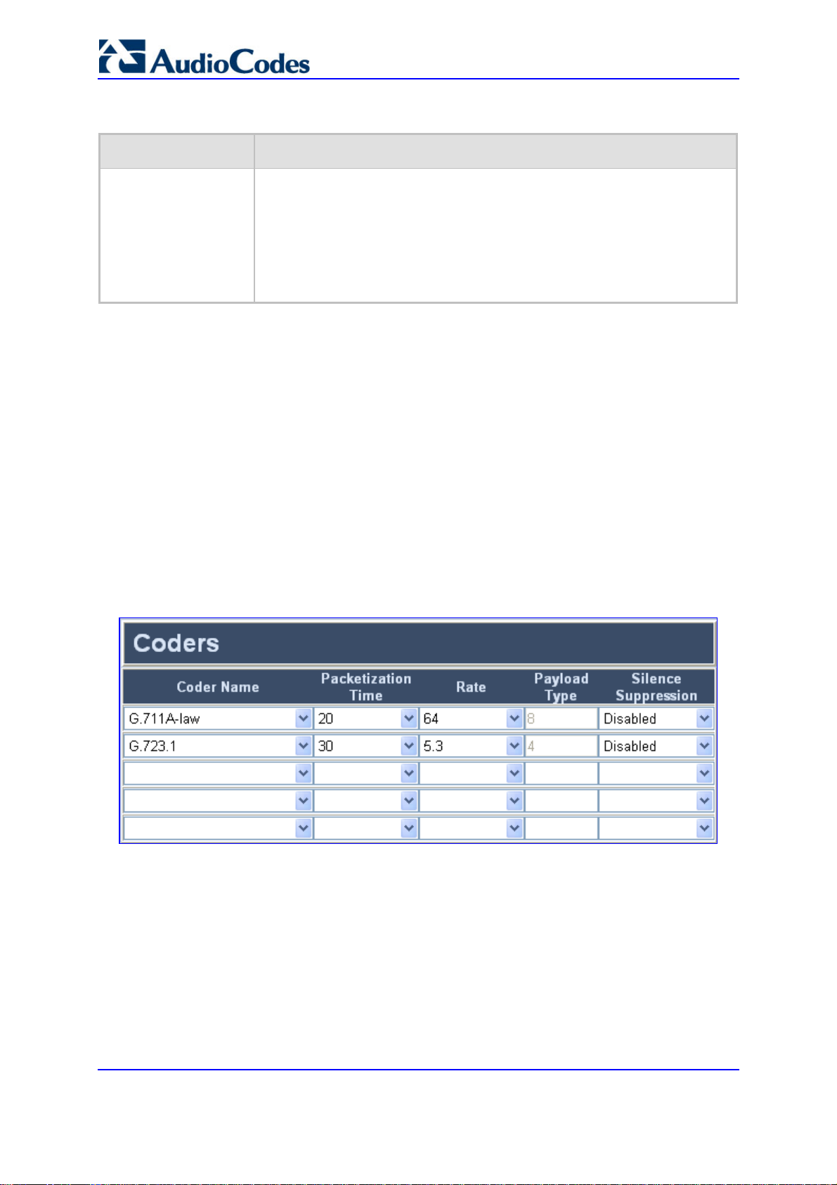
Mediant 2000 & TP-1610 & TP-260/UNI
Table 5-9: Proxy & Registration Parameters
Parameter Description
Mutual Authentication
Mode
[MutualAuthentication
Mode]
5.5.1.3 Coders
The Coders option allows you to configure the first to fifth preferred coders (and their attributes) for the gateway. The first coder is the highest priority coder and is used by the gateway whenever possible. If the far-end gateway cannot use the coder assigned as the first coder, the gateway attempts to use the next coder and so forth.
You can also configure the Coders table using the ini file parameter CoderName (refer to
'SIP Configuration Parameters' on page 295).
¾ To configure the gateway's coders, take these 9 steps:
1. Open the 'Coders' screen (Protocol Management menu > Protocol Definition
submenu > Coders option).
Determines the gateway's mode of operation when Authentication and Key
Agreement (AKA) Digest Authentication is used.
Valid options include:
[0] Optional = Incoming requests that don't include AKA authentication
information are accepted.
[1] Mandatory = Incoming requests that don't include AKA authentication
information are rejected.
Figure 5-10: Coders Screen
2. From the 'Coder Name' drop-down list, select the coder you want to use. For the full
list of available coders and their corresponding attributes, refer to the table below.
3. From the 'Packetization Time' drop-down list, select the packetization time (in msec)
for the coder you selected. The packetization time determines how many coder
payloads are combined into a single RTP packet.
4. From the 'Rate' drop-down list, select the bit rate (in kbps) for the coder you selected.
5. In the 'Payload Type' field, if the payload type for the coder you selected is dynamic,
enter a value from 0 to 120 (payload types of 'well-known' coders cannot be modified).
The payload type identifies the format of the RTP payload.
SIP User's Manual 96 Document #: LTRT-68806
Page 97

SIP User's Manual 5. Web-based Management
6. From the 'Silence Suppression' drop-down list, enable or disable the silence
suppression option for the coder you selected.
7. Repeat steps 2 through 6 for the second to fifth coders (optional).
8. Click the Submit button to save your changes.
9. To save the changes to flash memory, refer to 'Saving Configuration' on page 256.
Notes:
• Each coder (i.e., 'Coder Name') can appear only once.
• If packetization time and / or rate are not specified, the default value is
applied.
• The ptime specifies the packetization time the gateway expects to
receive. The gateway always uses the ptime requested by the remote
side for sending RTP packets.
• Only the ptime of the first coder in the defined coder list is declared in
INVITE / 200 OK SDP, even if multiple coders are defined.
• For G.729, it's also possible to select silence suppression without
adaptations.
• If the coder G.729 is selected and silence suppression is disabled (for
this coder), the gateway includes the string 'annexb=no' in the SDP of the
relevant SIP messages. If silence suppression is enabled or set to
'Enable w/o Adaptations', 'annexb=yes' is included. An exception to this
logic is when the remote gateway is a Cisco device (IsCiscoSCEMode).
• For an explanation on V.152 support (and implementation of T.38 and
VBD coders), refer to 'Supporting V.152 Implementation' on page 347.
• A pre-defined table can be configured to provide a set of rules for
automatic AMR rate change. The decision for the change is based upon
packet loss rate. To obtain more information about this option, contact
AudioCodes.
Table 5-10: Supported Coders
Coder Name Packetization Time Rate Payload Type Silence Suppression
G.711 A-law
[g711Alaw64k]
10, 20 (default), 30,
40, 50, 60, 80, 100,
Always 64 Always 8 Disable [0]
Enable [1]
120
G.711 µ-law
[g711Ulaw64k]
10, 20 (default), 30,
40, 50, 60, 80, 100,
Always 64 Always 0 Disable [0]
Enable [1]
120
G.729
[g729]
10, 20 (default), 30,
40, 50, 60, 80, 100
Always 8 Always 18 Disable [0]
Enable [1]
Enable w/o
Adaptations [2]
G.723.1
[g7231]
30 (default), 60, 90,
120
5.3 [0], 6.3
[1] (default)
Always 4 Disable [0]
Enable [1]
Version 5.2 97 September 2007
Page 98

Mediant 2000 & TP-1610 & TP-260/UNI
Table 5-10: Supported Coders
Coder Name Packetization Time Rate Payload Type Silence Suppression
G.726
[g726]
GSM-FR
[gsmFullRate]
GSM-EFR
[gsmEnhancedFullRate]
AMR
[Amr]
EVRC
[Evrc]
iLBC
[iLBC]
10, 20 (default), 30,
40, 50, 60, 80, 100,
120
16 [0], 24 [1],
32 [2]
(default)
40 [3]
20 (default), 40, 60,
80
0, 20 (default), 30,
40, 50, 60, 80, 100
Always 13 Always 3 Disable [0]
12.2 Dynamic (0-
20 (default) 4.75 [0], 5.15
[1], 5.90 [2],
6.70 [3], 7.40
[4], 7.95 [5],
10.2 [6], 12.2
[7] (default)
20 (default), 40,60,
80, 100
Variable [0]
(default), 1/8
[1], 1/2 [3],
20 (default), 40, 60,
Full [4]
15 (default)
80, 100, 120
30 (default), 60, 90,
13
120
Dynamic (0-
120)
120)
Dynamic (0-
120)
Dynamic (0-
120)
Dynamic (0-
120)
Disable [0]
Enable [1]
Enable [1]
Disable [0]
Enable [1]
Disable [0]
Enable [1]
Disable [0]
Enable [1]
Disable [0]
Enable [1]
MS-GSM
[gsmMS]
NetCoder
[NetCoder]
QCELP
[QCELP]
Transparent
[Transparent]
G.711A-law_VBD
[g711AlawVbd]
G.711U-law_VBD
[g711UlawVbd]
T.38
[t38fax]
40 (default) Always 13 Always 3 Disable [0]
Enable [1]
20 (default), 40, 60,
80, 100, 120
6.4 [0];
7.2 [1]
8.0 [2]
8.8 [3]
51
52
53
54
Disable [0]
Enable [1]
(default)
20 (default), 40, 60,
80, 100, 120
20 (default), 40, 60,
80, 100, 120
10, 20 (default), 30,
40, 50, 60, 80, 100,
Always 13 Always 12 Disable [0]
Enable [1]
Always 64 Dynamic (0-
120)
Always 64 Dynamic (0-
Disable [0]
Enable [1]
N/A
120)
120
10, 20 (default), 30,
40, 50, 60, 80, 100,
Always 64 Dynamic (0-
120)
N/A
120
N/A N/A N/A N/A
SIP User's Manual 98 Document #: LTRT-68806
Page 99
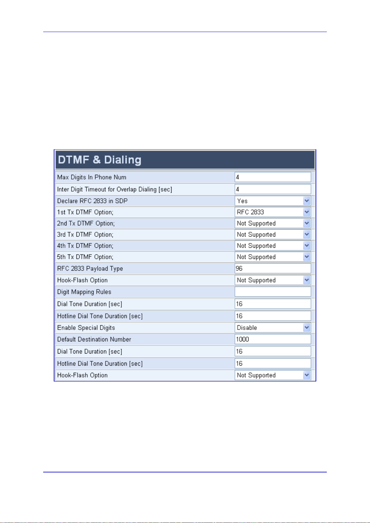
SIP User's Manual 5. Web-based Management
5.5.1.4 DTMF & Dialing Parameters
The DTMF & Dialing option is used to configure parameters associated with dual-tone
multi-frequency (DTMF) and dialing.
¾ To configure the DTMF and dialing parameters, take these 4 steps:
1. Open the 'DTMF & Dialing' screen (Protocol Management menu > Protocol
Definition submenu > DTMF & Dialing option).
Figure 5-11: DTMF & Dialing Screen
2. Configure the DTMF and dialing parameters according to the table below.
3. Click the Submit button to save your changes.
4. To save the changes to flash memory, refer to 'Saving Configuration' on page 256.
Version 5.2 99 September 2007
Page 100

Mediant 2000 & TP-1610 & TP-260/UNI
Table 5-11: DTMF and Dialing Parameters
Parameter Description
Max Digits in Phone Num
[MaxDigits]
Inter Digit Timeout for
Overlap Dialing [sec]
[TimeBetweenDigits]
Declare RFC 2833 in
SDP
[RxDTMFOption]
Defines the maximum number of collected destination number digits that
can be received from the Tel side when Tel-to-IP overlap dialing is
performed (ISDN uses overlap dialing). When the number of collected
digits reaches the maximum, the gateway uses these digits for the called
destination number.
The valid range is 1 to 49. The default value is 30.
Notes: Digit Mapping Rules can be used instead.
Defines the time (in seconds) that the gateway waits between digits that
are received from the Tel side when Tel-to-IP overlap dialing is performed
(ISDN uses overlap dialing). When this inter-digit timeout expires, the
gateway uses the collected digits for the called destination number.
The valid range is 1 to 10 seconds. The default value is 4 seconds.
Defines the supported Receive DTMF negotiation method.
[0] No = Don't declare RFC 2833 telephony-event parameter in SDP.
[3] Yes = Declare RFC 2833 telephony-event parameter in SDP
(default).
The gateway is designed to always be receptive to RFC 2833 DTMF relay
packets. Therefore, it is always correct to include the 'telephony-event'
parameter as a default in the SDP. However some gateways use the
absence of the 'telephony-event' from the SDP to decide to send DTMF
digits in-band using G.711 coder. If this is the case, you can set
RxDTMFOption to 0.
SIP User's Manual 100 Document #: LTRT-68806
 Loading...