

Page 1

Configuration Note
AudioCodes Mediant™ Family of Media Gateways & Session Border Controllers
Connecting Zoom Phone
Carrier Peering with
AudioCodes SBC
Page 2

Page 3

Configuration Note Contents
Table of Contents
1 Introduction ......................................................................................................... 9
1.1 About the Zoom Phone System .............................................................................. 9
1.2 About AudioCodes SBC Product Series ................................................................. 9
2 Configuring Zoom Phone System .................................................................... 11
3 Configuring AudioCodes' SBC ........................................................................ 13
3.1 Prerequisites ........................................................................................................ 13
3.2 Validate AudioCodes SBC License ....................................................................... 14
3.3 SBC Configuration Concept .................................................................................. 14
3.4 Configure IP Network Interfaces ........................................................................... 15
3.4.1 Configure LAN and WAN VLANs ............................................................................15
3.4.2 Configure Network Interfaces ..................................................................................16
3.5 Configure TLS Context for Zoom .......................................................................... 17
3.5.1 Configure the NTP Server Address .........................................................................17
3.5.2 Create a TLS Context for Zoom Phone System ......................................................18
3.5.3 Generate a CSR and Obtain the Certificate from a Supported CA .........................20
3.5.4 Deploy the SBC and Root / Intermediate Certificates on the SBC ..........................22
3.6 Configure Media Realms ...................................................................................... 24
3.7 Configure SIP Signaling Interfaces ....................................................................... 25
3.8 Configure Proxy Sets and Proxy Address ............................................................. 26
3.8.1 Configure Proxy Sets ...............................................................................................26
3.8.2 Configure a Proxy Address ......................................................................................27
3.9 Configure the Dial Plan Table (Customer DIDs) ................................................... 29
3.10 Configure Call Setup Rules .................................................................................. 30
3.11 Configure Message Manipulation Rules ............................................................... 31
3.12 Configure a Coder Group ..................................................................................... 35
3.13 Configure an IP Profiles ........................................................................................ 37
3.14 Configure IP Groups ............................................................................................. 39
3.15 Configure SRTP ................................................................................................... 41
3.16 Configure IP-to-IP Call Routing Rules .................................................................. 42
3.17 Configure Firewall Settings (Optional) .................................................................. 43
3.18 Miscellaneous Configuration ................................................................................. 44
3.18.1 Configuring Mutual TLS Authentication for SIP .......................................................44
3.18.2 Optimizing CPU Cores Usage for a Specific Service (relevant for Mediant 9000 and
Software SBC only) ..............................................................................................................45
4 Verify the Pairing between the SBC and Zoom Phone System ..................... 47
A Zoom Data Centers ........................................................................................... 49
Zoom Phone Carrier Peering 3 AudioCodes SBCs
Page 4

Zoom Phone Carrier Peering
List of Figures
Figure 3-1: Connection Topology - Network Interfaces .........................................................................13
Figure 3-2: SBC Configuration Concept .................................................................................................14
Figure 3-3: Network Interfaces in the Topology with all entities on the WAN ........................................15
Figure 3-4: Configured VLANs in the Ethernet Device Table.................................................................15
Figure 3-5: Configuration Example of the IP Interfaces Table ...............................................................16
Figure 3-6: Configuring NTP Server Address.........................................................................................17
Figure 3-7: Configuration of TLS Context for Zoom Phone System ......................................................18
Figure 3-8: TLS Context for Zoom Phone System and Interface to Manage the Certificates ................19
Figure 3-9: Example of Certificate Signing Request Page .....................................................................21
Figure 3-10: Uploading the Certificate Obtained from the Certification Authority ..................................22
Figure 3-11: Message Indicating Successful Upload of the Certificate ..................................................22
Figure 3-12: Certificate Information Example .........................................................................................23
Figure 3-13: Configured Trusted Certificates Page ................................................................................23
Figure 3-14: Configuration Example Media Realms in Media Realm Table ..........................................24
Figure 3-15: Configuration Example of SIP Signaling Interfaces ...........................................................25
Figure 3-16: Configuration Example Proxy Sets in Proxy Sets Table ....................................................26
Figure 3-17: Configuring Proxy Address for Zoom Phone System Interface .........................................27
Figure 3-18: Configuring Proxy Address for Customer 1 SIP Trunk ......................................................28
Figure 3-19: Dial Plan Rule Table - Add Dialog Box ..............................................................................29
Figure 3-20: Configuring SIP Message Manipulation Rule 0 (for Zoom IP Group) ................................31
Figure 3-21: Configuring SIP Message Manipulation Rule 1 (for Zoom IP Group) ................................32
Figure 3-22: Configuring SIP Message Manipulation Rule 2 (for Customers SIP Trunks) ....................33
Figure 3-23: Configuring SIP Message Manipulation Rule 3 (for Zoom IP Group) ................................34
Figure 3-24: Configuring Coder Group for Zoom Phone System ...........................................................35
Figure 3-25: Configuring Allowed Coders Group for Zoom Phone System ...........................................36
Figure 3-26: Configuring Allowed Coders for Zoom Phone System ......................................................36
Figure 3-27: Configuration Example IP Groups in the IP Group Table ..................................................40
Figure 3-28: Configuring Media Security Parameter ..............................................................................41
Figure 3-29: Configured IP-to-IP Routing Rules in IP-to-IP Routing Table ............................................42
Figure 4-1: Proxy Set Status ..................................................................................................................47
Configuration Note 4 Document #: LTRT-29341
Page 5

Configuration Note Contents
List of Tables
Table 3-1: Configuration Example of the IP Interfaces Table ................................................................16
Table 3-2: New TLS Context ..................................................................................................................18
Table 3-3: Configuration Example Media Realms in Media Realm Table .............................................24
Table 3-4: Configuration Example of SIP Signaling Interfaces ..............................................................25
Table 3-5: Configuration Example Proxy Sets in Proxy Sets Table .......................................................26
Table 3-6: Configuration Proxy Address for Zoom Phone System ........................................................27
Table 3-7: Configuration Proxy Address for Customer 1 SIP Trunk ......................................................28
Table 3-8: Dial Plan Carrier Customers .................................................................................................29
Table 3-9: Call Setup Rules Table .........................................................................................................30
Table 3-10: Configuration Example: Zoom IP Profile .............................................................................37
Table 3-11: Configuration Example: Customer 1 SIP Trunk IP Profile ..................................................38
Table 3-12: Firewall Table Rules ............................................................................................................43
Table A-1: Regional instances resolve to the following IP addresses ...................................................49
Table A-2: Regional Media Traffic and Ports .........................................................................................49
Zoom Phone Carrier Peering 5 AudioCodes SBCs
Page 6

Zoom Phone Carrier Peering
This page is left intentionally blank.
Configuration Note 6 Document #: LTRT-29341
Page 7

Configuration Note Notices
Notice
Information contained in this document is believed to be accurate and reliable at the time of
printing. However, due to ongoing product improvements and revisions, AudioCodes cannot
guarantee accuracy of printed material after the Date Published nor can it accept responsibility
for errors or omissions. Updates to this document can be downloaded from
https://www.audiocodes.com/library/technical-documents.
This document is subject to change without notice.
Date Published: March-10-2021
WEEE EU Directive
Pursuant to the WEEE EU Directive, electronic and electrical waste must not be disposed of
with unsorted waste. Please contact your local recycling authority for disposal of this product.
Customer Support
Customer technical support and services are provided by AudioCodes or by an authorized
AudioCodes Service Partner. For more information on how to buy technical support for
AudioCodes products and for contact information, please visit our at
https://www.audiocodes.com/services-support/maintenance-and-support
Stay in the Loop with AudioCodes
Abbreviations and Terminology
Each abbreviation, unless widely used, is spelled out in full when first used.
.
Zoom Phone Carrier Peering 7 AudioCodes SBCs
Page 8
Zoom Phone Carrier Peering
Related Documentation
Document Name
Mediant 500 Gateway & E-SBC User's Manual
Mediant 500L Gateway & E-SBC User's Manual
Mediant 800 Gateway & E-SBC User's Manual
Mediant 1000B Gateway & E-SBC User's Manual
Mediant 2600 E-SBC User's Manual
Mediant 4000 SBC User's Manual
Mediant 9000 SBC User's Manual
Mediant Software SBC User's Manual
Gateway and SBC CLI Reference Guide
SIP Message Manipulation Reference Guide
AudioCodes Configuration Notes
Document Revision Record
LTRT Description
29340 Initial document release.
29341 Added call setup rule for outgoing messages towards Zoom; added message manipulation
rule towards Zoom.
Documentation Feedback
AudioCodes continually strives to produce high quality documentation. If you have any
comments (suggestions or errors) regarding this document, please fill out the Documentation
Feedback form on our website at https://online.audiocodes.com/documentation-feedback
.
Configuration Note 8 Document #: LTRT-29341
Page 9

Configuration Note 1. Introduction
1 Introduction
This document describes how to connect Zoom Phone System to multiple customers using
AudioCodes' SBC in Hosting mode and refers to the AudioCodes SBC configuration only.
This document is intended for IT or telephony professionals.
Note: To zoom in on screenshots of Web interface configuration examples,
press Ctrl and +.
1.1 About the Zoom Phone System
Zoom Phone is a fully featured cloud PBX designed with security, reliability, scalability and
centralized management in mind. Zoom Phone was built from the ground up to seamlessly
integrate with the Zoom Collaboration platform to deliver a feature-rich UCaaS user
experience. Zoom Phone offers various deployment options providing organizations with the
flexibility to migrate and deploy the platform in a manner that best suits their requirements.
Zoom Phone leverages global carrier relationships to deliver PSTN connectivity in many
regions of the world offering phone number portability to Zoom in most regions thereby
simplifying the telephony environment with one partner for your PBX and PSTN connectivity
needs. While native Zoom Phone meets the requirements of most organizations, it’s
understood that some organizations have environments that may need additional
functionality for global support or migration strategies. For organizations with such diverse
requirements of their telephony environments, Zoom’s Premise Peering solution is offered.
Zoom Phone Premise Peering provides organizations with flexibility and seamless options to
migrate their voice workloads to the cloud. This is accomplished by providing two connection
types; Premise Peering PSTN (formally referred to as Bring Your Own Carrier - BYOC) and/or
Premise Peering PBX (formally referred to as Bring Your Own PBX - BYOP). Zoom Phone
Premise Peering PSTN enables organizations to leverage their existing telephony carrier
PSTN environment for Zoom Phone connectivity. Using this functionality organizations can
connect Zoom Phone with virtually any telephony carrier.
1.2 About AudioCodes SBC Product Series
AudioCodes' family of SBC devices enables reliable connectivity and security between the
enterprise's VoIP network and the service provider's VoIP network.
The SBC provides perimeter defense as a way of protecting enterprises from malicious VoIP
attacks; mediation for allowing the connection of any PBX and/or IP-PBX to any service
provider; and Service Assurance for service quality and manageability.
Designed as a cost-effective appliance, the SBC is based on field-proven VoIP and network
services with a native host processor, allowing the creation of purpose-built multiservice
appliances, providing smooth connectivity to cloud services, with integrated quality of service,
SLA monitoring, security and manageability. The native implementation of the SBC provides
a host of additional capabilities that are not possible with standalone SBC appliances such
as VoIP mediation, PSTN access survivability, and third-party value-added services
applications. This enables enterprises to utilize the advantages of converged networks and
eliminate the need for standalone appliances.
AudioCodes' SBC is available as an integrated solution running on top of its field-proven
Mediant Media Gateway and Multi-Service Business Router platforms, or as a software-only
solution for deployment with third-party hardware. The SBC can be offered as a Virtualized
SBC, supporting the following platforms: Hyper-V, AWS, AZURE, AWP, KVM and VMWare.
Zoom Phone Carrier Peering 9 AudioCodes SBCs
Page 10

Zoom Phone Carrier Peering
This page is intentionally left blank.
Configuration Note 10 Document #: LTRT-29341
Page 11

Configuration Note 2. Configuring Zoom Phone System
2 Configuring Zoom Phone System
For configuring the Zoom Phone System, refer to Zoom Help Center at
https://support.zoom.us/hc/en-us/articles/360001297663-Getting-started-with-Zoom-Phoneadmin-.
Notes: Before you begin configuration:
• Contact your Zoom Representative to enable SIP groups and set up SIP trunks
that are directed toward your SBC for your Zoom Phone account.
• Make sure you have Zoom Portal admin credentials. Be aware that each
customer needs to have a Zoom Phone admin account and all Zoom Phone
related configuration will be done by the customer and not by the carrier.
Zoom Phone Carrier Peering 11 AudioCodes SBCs
Page 12

Zoom Phone Carrier Peering
This page is left intentionally blank.
Configuration Note 12 Document #: LTRT-29341
Page 13
Configuration Note 3. Configuring AudioCodes' SBC
Internet
Cust omer 1
Manag ement
Stat ion (OAMP)
Cust omer 1 N etwo rk
LAN
Firew all
Cli ent
Cli ent
Manag ement
Stat ion (OAMP)
Cust omer 2 N etwo rk
LAN
Firew all
Cli ent
Cli ent
Cust omer 2
ITSP
PSTN
ITSP
PSTN
Session Border Controller
Cust omer 1
Cli ent
Cust omer 2
Cli ent
suite of
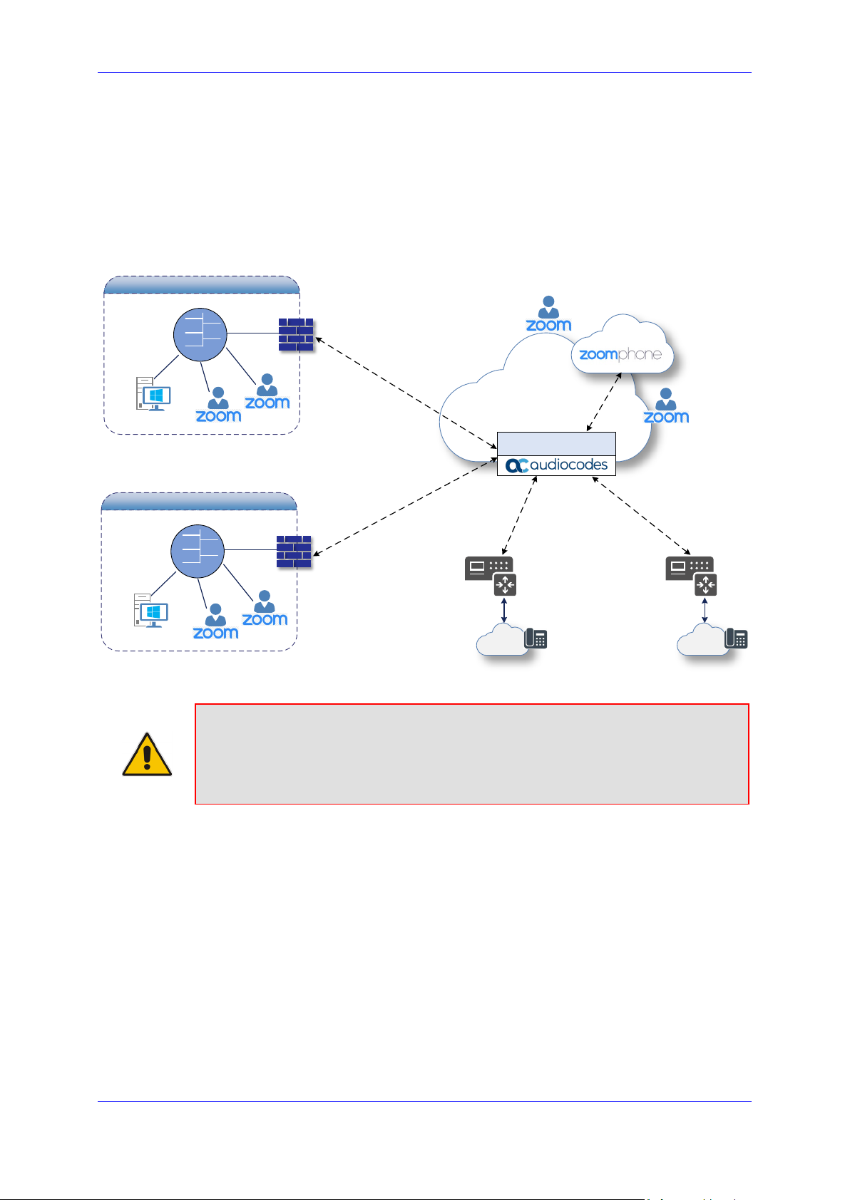
3 Configuring AudioCodes' SBC
This section shows how to configure AudioCodes' SBC for internetworking with Zoom Phone
System. The figure below shows an example of the connection topology for the Zoom Phone
System Premise Peering Mode. Multiple connection entities are shown in the figure:
Zoom Phone Systems
Service Provider Customers SIP Trunks
Figure 3-1: Connection Topology - Network Interfaces
Note: This document shows how to pair between the AudioCodes' hosting SBC and
the Zoom Phone System with a Customers SIP Trunks. For detailed configuration of
other entities in the deployment such as the SIP Trunk Provider and the local IP-PBX,
see AudioCodes' SIP Trunk Configuration Notes (in the Interoperability
documents).
3.1 Prerequisites
Before you begin configuration, make sure you have obtained the following for each Hosting
SBC you wish to pair:
Public IP address
Public certificate that is issued by one of the Zoom supported CAs
Zoom Phone Carrier Peering 13 AudioCodes SBCs
Page 14
Zoom Phone Carrier Peering
Pro xy Set
(Customer1
SIP Trunk)
Pro xy Set
(Customer2
SIP Trunk)
Pro xy Set
(Customer3
SIP Trunk)
Phone System
IP Group
(Customer1
SIP Trunk)
IP Group
(Customer2
SIP Trunk)
IP Group
(Customer3
SIP Trunk)
SIP
Interface
SBC
SIP
Interface
IP Group
SI P T r unk
SI P T r unk
SI P T r unk
3.2 Validate AudioCodes SBC License
Zoom has successfully conducted validation tests with AudioCodes' Mediant SBC
Ver. 7.20A.258. For implementing the configuration described in this document, the
AudioCodes SBC must be installed with a License Key that includes the following features:
Number of SBC sessions (based on requirements)
Transcoding sessions (only if media transcoding is needed)
Coders (based on requirements)
For more information about the License Key, contact your AudioCodes sales representative.
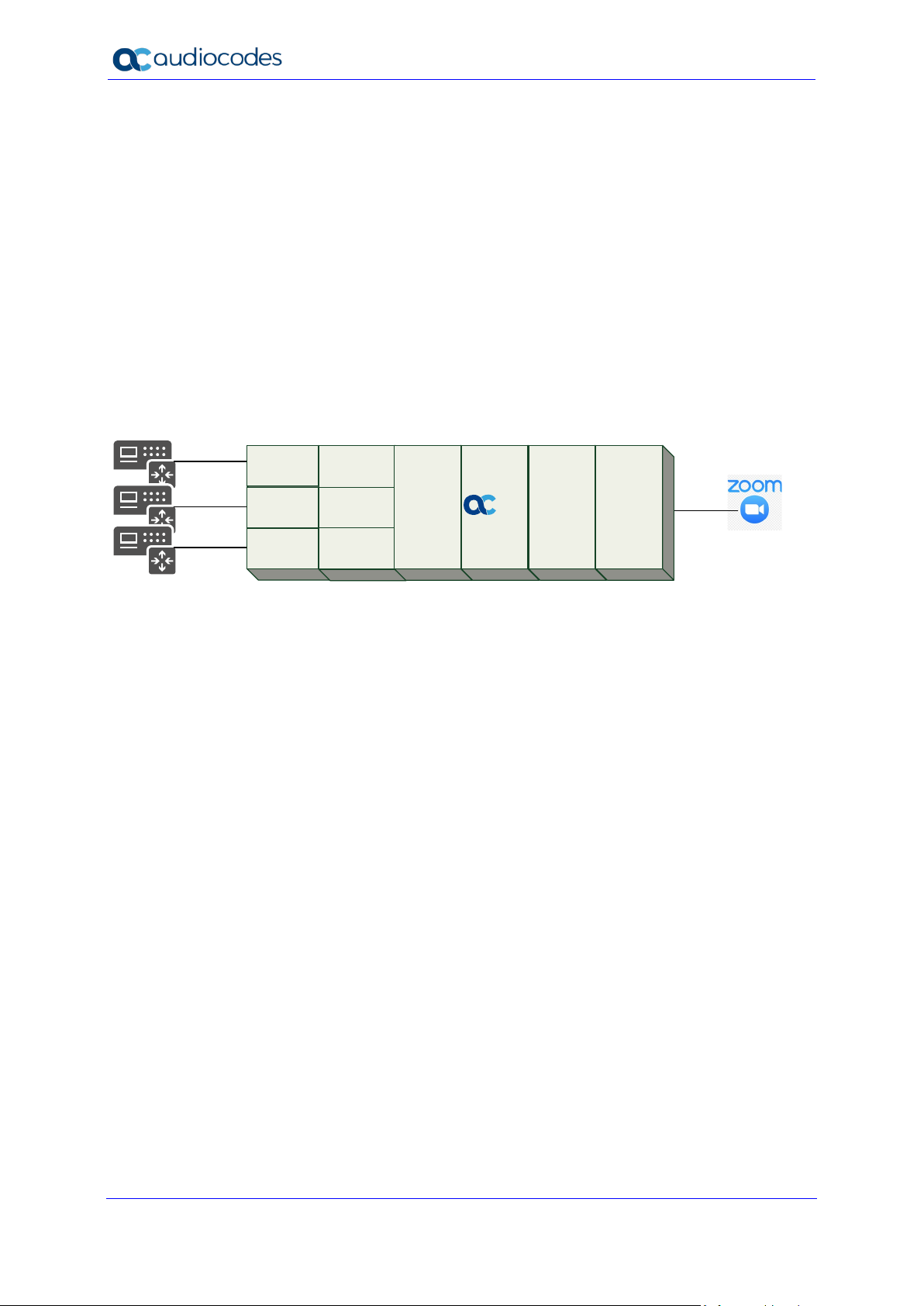
3.3 SBC Configuration Concept
The figure below illustrates the underlying concept of the configuration of AudioCodes’ SBC
device.
Figure 3-2: SBC Configuration Concept
The routing from the SIP Trunks to Zoom Phone System and vice versa is dependent on the
Class 4 switch routing method. The routing decision can be based on:
Customer DID Range
Trunk Context (TGRP)
IP Interface
SIP Interface (UDP/TCP Port)
Host name
The configuration shown in this document is based on a Customer DID Range using a Dial
Plan. For more information, see the AudioCodes' Documentation suite.
Configuration Note 14 Document #: LTRT-29341
Page 15
Configuration Note 3. Configuring AudioCodes' SBC
Management
Station (OAMP )
LAN
WAN
DMZ
LAN Port
LAN Port
Vlan ID 1
Vlan ID 2
Session B order Con troller
Firew all
Phone System
ITSP1
ITSP2
ITSP3
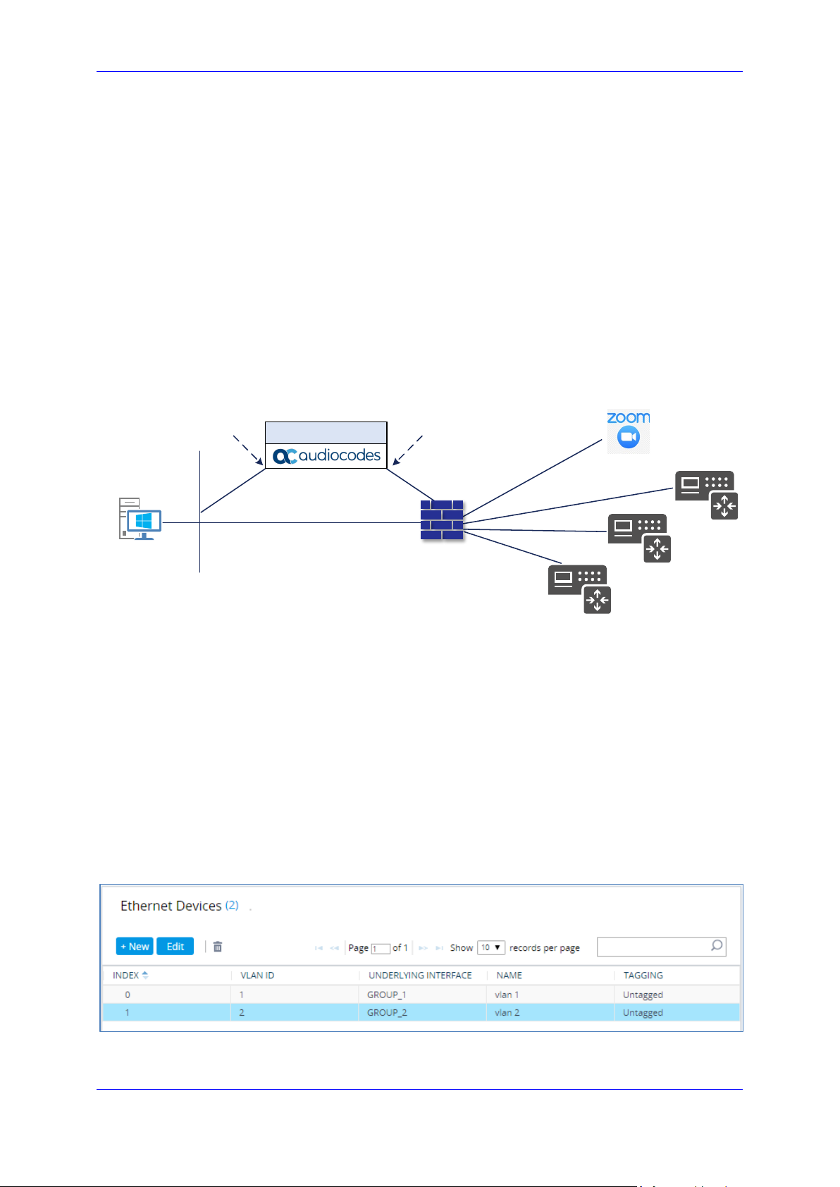
3.4 Configure IP Network Interfaces
This section describes how to configure the SBC's IP network interfaces. There are several
ways to deploy the SBC:
SBC interfaces with the following IP entities:
• Zoom Phone System
• Customers SIP Trunks
Physical connection: The type of physical connection depends on the method used to
connect to the Enterprise's network. In this example topology, SBC connects to the
LAN and DMZ using dedicated Ethernet ports (i.e., two ports and two network cables
are used).
SBC also uses two logical network interfaces:
• LAN (VLAN ID 1)
• DMZ (VLAN ID 2)
Figure 3-3: Network Interfaces in the Topology with all entities on the WAN
3.4.1 Configure LAN and WAN VLANs
This section describes how to define VLANs for each of the following interfaces:
LAN Interface (assigned the name "LAN_IF")
WAN Interface (assigned the name "WAN_IF")
To configure VLANs:
1. Open the Ethernet Device table (Setup menu > IP Network tab > Core Entities
folder > Ethernet Devices).
2. There will be one existing row for VLAN ID 1 and underlying interface GROUP_1.
3. Add another VLAN ID 2 for the WAN side.
Figure 3-4: Configured VLANs in the Ethernet Device Table
Zoom Phone Carrier Peering 15 AudioCodes SBCs
Page 16

Zoom Phone Carrier Peering
Length
3.4.2 Configure Network Interfaces
This section describes how to configure the IP network interfaces for each of the following
interfaces:
LAN Interface (assigned the name "LAN_IF")
WAN Interface (assigned the name "WAN_IF")
To configure network parameters for both LAN and WAN interfaces:
1. Open the IP Interfaces table (Setup menu > IP Network tab > Core Entities folder > IP
Interfaces).
2. Configure the IP interfaces as follows (your network parameters might be different):
Table 3-1: Configuration Example of the IP Interfaces Table
Index
0
1
Application
Types
OAMP+ Media +
Control
Media + Control
(as this interface
points to the
internet, enabling
OAMP is not
recommended)
The configured IP network interfaces are shown below:
Interfac
e Mode
IPv4
Manual
IPv4
Manual
Figure 3-5: Configuration Example of the IP Interfaces Table
IP Address
10.15.77.77 16 10.15.0.1
195.189.192.157
(DMZ IP address
of SBC)
Prefix
25
Gateway DNS I/F Name
10.15.27.
1
According
195.189.192.12
9 (router's IP
address)
to your
Internet
provider's
instructions
Ethernet
Device
LAN_IF vlan 1
WAN_IF vlan 2
Configuration Note 16 Document #: LTRT-29341
Page 17

Configuration Note 3. Configuring AudioCodes' SBC
3.5 Configure TLS Context for Zoom
This section describes how to configure the SBC for using a TLS connection with the Zoom
Phone System. This configuration is essential for a secure SIP TLS connection.
This certificate module is based on the GoDaddy Certificate Chain. For more certificate
structure options, refer to the Zoom Phone System documentation.
3.5.1 Configure the NTP Server Address
This section describes how to configure the NTP server's IP address. It is recommended to
implement an NTP server (Microsoft NTP server or another global server) to ensure that the
SBC receives the current date and time. This is necessary for validating certificates of remote
parties. It is important, that the NTP server is located on the OAMP IP Interface (LAN_IF in
our case) or will be accessible through it.
To configure the NTP server address:
1. Open the Time & Date page (Setup menu > Administration tab > Time & Date).
2. In the 'Primary NTP Server Address' field, enter the IP address of the NTP server
(e.g., 10.15.28.1).
Figure 3-6: Configuring NTP Server Address
3. Click Apply.
Zoom Phone Carrier Peering 17 AudioCodes SBCs
Page 18

Zoom Phone Carrier Peering
3.5.2 Create a TLS Context for Zoom Phone System
The section below describes how to request a certificate for the SBC WAN interface and
configure it, based on the example of the GoDaddy Global Root CA. The certificate is used
by the SBC to authenticate the connection with the Zoom Phone System.
The procedure involves the following main steps:
Create a TLS Context for Zoom Phone System
Generate a Certificate Signing Request (CSR) and obtain the certificate from a
supported Certification Authority
Deploy the SBC and Root / Intermediate certificates on the SBC
To create a TLS Context for Zoom Phone System:
1. Open the TLS Contexts page (Setup menu > IP Network tab > Security folder >
TLS Contexts).
2. Create a new TLS Context by clicking +New, and then configure the parameters
using the table below as reference.
Table 3-2: New TLS Context
Index Name TLS Version
1 Zoom (arbitrary descriptive name) TLSv1.2
All other parameters can be left unchanged with their default values.
Figure 3-7: Configuration of TLS Context for Zoom Phone System
3. Click Apply; you should see the new TLS Context and option to manage the
certificates at the bottom of 'TLS Context' table.
Configuration Note 18 Document #: LTRT-29341
Page 19

Configuration Note 3. Configuring AudioCodes' SBC
Figure 3-8: TLS Context for Zoom Phone System and Interface to Manage the Certificates
Zoom Phone Carrier Peering 19 AudioCodes SBCs
Page 20

Zoom Phone Carrier Peering
3.5.3 Generate a CSR and Obtain the Certificate from a Supported CA
This section shows how to generate a Certificate Signing Request (CSR) and obtain the
certificate from a supported Certification Authority.
To generate a Certificate Signing Request (CSR) and obtain the certificate from a
supported Certification Authority:
1. Open the TLS Contexts page (Setup menu > IP Network tab > Security folder >
TLS Contexts).
2. In the TLS Contexts page, select the Zoom TLS Context index row, and then click
the Change Certificate link located below the table; the Context Certificates page
appears.
3. Under the Certificate Signing Request group, do the following:
a. In the 'Common Name [CN]' field, enter the SBC FQDN name
(for example, sbc.audiocodes.com).
b. In the '1st Subject Alternative Name [SAN]' field, change the type to ‘DNS’
and enter the SBC FQDN name (based on example above,
sbc.audiocodes.com).
c. Change the 'Private Key Size' based on the requirements of your
Certification Authority. Many CAs do not support private key of size 1024.
d. To change the key size on TLS Context, go to: Generate New Private Key
and Self-Signed Certificate, change the 'Private Key Size' and then click
Generate Private-Key. To use 2048 as a Private Key Size value, you can
click Generate Private-Key without changing the default key size value.
e. Fill in the rest of the request fields according to your security provider's
instructions.
f. Click the Create CSR button; a textual certificate signing request is displayed
in the area below the button:
Configuration Note 20 Document #: LTRT-29341
Page 21

Configuration Note 3. Configuring AudioCodes' SBC
Figure 3-9: Example of Certificate Signing Request Page
4. Copy the CSR from the line "----BEGIN CERTIFICATE" to "END CERTIFICATE
REQUEST----" to a text file (such as Notepad), and then save it to a folder on your
computer with the file name, for example certreq.txt.
5. Send certreq.txt file to the Certified Authority Administrator for signing.
Zoom Phone Carrier Peering 21 AudioCodes SBCs
Page 22

Zoom Phone Carrier Peering
3.5.4 Deploy the SBC and Root / Intermediate Certificates on the SBC
After obtaining the SBC signed and Trusted Root/Intermediate Certificate from the CA, install
the following:
SBC certificate
Root / Intermediate certificates:
To install the SBC certificate:
1. In the SBC's Web interface, return to the TLS Contexts page and do the following:
a. In the TLS Contexts page, select the required TLS Context index row, and then
click the Change Certificate link located below the table; the Context Certificates
page appears.
b. Scroll down to the Upload certificates files from your computer group, click the
Choose File button corresponding to the 'Send Device Certificate...' field,
navigate to the certificate file obtained from the CA, and then click Load File to
upload the certificate to the SBC.
Figure 3-10: Uploading the Certificate Obtained from the Certification Authority
2. Validate that the certificate was uploaded correctly. A message indicating that the
certificate was uploaded successfully is displayed in blue in the lower part of the page:
Figure 3-11: Message Indicating Successful Upload of the Certificate
3. In the SBC's Web interface, return to the TLS Contexts page, select the required TLS
Context index row, and then click the Certificate Information link, located at the bottom
of the TLS. Then validate the Key size, certificate status and Subject Name:
Configuration Note 22 Document #: LTRT-29341
Page 23

Configuration Note 3. Configuring AudioCodes' SBC
Figure 3-12: Certificate Information Example
4. In the SBC's Web interface, return to the TLS Contexts page.
a. In the TLS Contexts page, select the required TLS Context index row, and then
click the Trusted Root Certificates link, located at the bottom of the TLS Contexts
page; the Trusted Certificates page appears.
b. Click the Import button, and then select all Root/Intermediate Certificates
obtained from your Certification Authority to load.
5. Click OK; the certificate is loaded to the device and listed in the Trusted Certificates
store:
Figure 3-13: Configured Trusted Certificates Page
Note: The above method creates a signed certificate for an explicit device, on which
a Certificate Sign Request was generated (and signed with private key).
Zoom Phone Carrier Peering 23 AudioCodes SBCs
Page 24

Zoom Phone Carrier Peering
3.6 Configure Media Realms
Media Realms allow dividing the UDP port ranges for use on different interfaces. In the
example below, two Media Realms are configured:
One for the IP interface towards the Zoom Phone System, with the UDP port starting
at 10000 and the number of media session legs 1000 (you need to calculate number of
media session legs based on your usage).
One for the IP interface towards Customers SIP Trunks, with the UDP port range
starting at 6000 and the number of media session legs 1000.
To configure Media Realms:
1. Open the Media Realms table (Setup menu > Signaling & Media tab > Core Entities
folder > Media Realms).
2. Configure Media Realms as follows (you can use the default Media Realm - Index 0 -
however modify it):
Table 3-3: Configuration Example Media Realms in Media Realm Table
Index Name
0
1
Zoom
(arbitrary name)
Customers
(arbitrary name)
The configured Media Realms are shown in the figure below:
Figure 3-14: Configuration Example Media Realms in Media Realm Table
Topology
Location
Up WAN_IF 10000
WAN_IF 6000
IPv4 Interface
Name
Port Range
Start
Number of Media Session
Legs
1000 (media sessions
assigned with port range)
1000 (media sessions
assigned with port range)
Configuration Note 24 Document #: LTRT-29341
Page 25

Configuration Note 3. Configuring AudioCodes' SBC
3.7 Configure SIP Signaling Interfaces
This section shows how to configure SIP Signaling Interfaces. A SIP Interface defines a
listening port and type (UDP, TCP, or TLS) for SIP signaling traffic on a specific logical IP
network interface (configured in the Interface Table above) and Media Realm.
Note that the configuration of a SIP interface for the SIP Trunks shows an example and your
configuration might be different. For specific configuration of interfaces pointing to SIP trunks
and/or a third-party PSTN environment connected to the SBC, see the trunk / environment
vendor documentation.
AudioCodes also offers a comprehensive suite of documents covering the interconnection
between different trunks and equipment.
To configure a SIP interfaces:
1. Open the SIP Interface table (Setup menu > Signaling & Media tab > Core Entities
folder > SIP Interfaces).
2. Configure SIP Interfaces. You can use the default SIP Interface (Index 0), however
modify it as shown in the table below. The table below shows an example of the
configuration. You can change some parameters according to your requirements.
Table 3-4: Configuration Example of SIP Signaling Interfaces
Index Name
Zoom
0
1
(arbitrary
name)
Customers
(arbitrary
name)
The configured SIP Interfaces are shown in the figure below:
Network
Interface
WAN_IF SBC 0 0 5061
WAN_IF SBC
Application
Type
UDP Port
5060
(according to
Service
Provider
requirement)
TCP
Port
0 0
TLS
Port
Classification
Failure
Response Type
0
(Recommended
to prevent DoS
attacks)
0
(Recommended
to prevent DoS
attacks)
Media
Realm
Zoom
Custo
mers
Note: For enhanced security, AudioCodes recommends implementing a Mutual TLS
connection with the Zoom Phone System. For required configuration, see Section
3.18.1 on page 44.
Figure 3-15: Configuration Example of SIP Signaling Interfaces
Zoom Phone Carrier Peering 25 AudioCodes SBCs
Page 26

Zoom Phone Carrier Peering
3.8 Configure Proxy Sets and Proxy Address
3.8.1 Configure Proxy Sets
The Proxy Set and Proxy Address defines TLS parameters, IP interfaces, FQDN and the
remote entity's port. Proxy Sets can also be used to configure load balancing between
multiple servers. The example below covers configuration of a Proxy Sets for Zoom Phone
System and Customers SIP Trunks. Note that the configuration of a Proxy Set for the SIP
Trunks shows an example and your configuration might be different. For specific
configuration of interfaces directed to SIP Trunks and/or the third-party PSTN environment
connected to the SBC, see the trunk/environment vendor's documentation. AudioCodes also
offers a comprehensive suite of documents covering the interconnection between different
trunks and the equipment.
The Proxy Sets will later be applied to the VoIP network by assigning them to IP Groups.
To configure a Proxy Sets:
1. Open the Proxy Sets table (Setup menu > Signaling & Media tab > Core Entities folder
> Proxy Sets).
2. Configure Proxy Sets as shown in the table below:
Table 3-5: Configuration Example Proxy Sets in Proxy Sets Table
Index Name
0
1
2
3
Zoom
(arbitrary name)
Customer1
(arbitrary name)
Customer2
(arbitrary name)
Customer3
(arbitrary name)
The configured Proxy Sets are shown in the figure below:
Figure 3-16: Configuration Example Proxy Sets in Proxy Sets Table
SBC IPv4 SIP
Interface
Zoom Zoom
Customers Default
Customers Default
Customers Default
TLS Context
Name
Proxy Keep-
Alive
Using
Options
Using
Options
Using
Options
Using
Options
Redundancy
Mode
Homing Enable
- -
- -
- -
Proxy Hot
Swap
Note: On Hybrid SBCs (with Onboard PSTN interfaces) it’s recommended to leave
Proxy Set 0 unconfigured for possible future use for PSTN Fallback.
Configuration Note 26 Document #: LTRT-29341
Page 27

Configuration Note 3. Configuring AudioCodes' SBC
3.8.2 Configure a Proxy Address
This section shows how to configure a Proxy Address.
To configure a Proxy Address for Zoom:
1. Open the Proxy Sets table (Setup menu > Signaling & Media tab > Core Entities folder
> Proxy Sets) click the Proxy Set Zoom, and then click the Proxy Address link located
below the table; the Proxy Address table opens.
2. Click +New; the following dialog box appears:
Figure 3-17: Configuring Proxy Address for Zoom Phone System Interface
3. Configure the address of the Proxy Set according to the parameters described in the
table below:
Table 3-6: Configuration Proxy Address for Zoom Phone System
Index Proxy Address Transport Type Proxy Priority
0 us01peer01.am.zoom.us:5061 TLS 0 0
1 us01peer01.fr.zoom.us:5061 TLS 0 0
4. Click Apply.
Note: The current example is based on configuration Zoom Europe Data Center’s IP
address (FQDN). In your implementation, the IP address may be different according
to your region. Refer to Appendix A on page 49 for a list of FQDNs / IP addresses of
other Zoom Regional Data Centers.
Proxy Random
Weight
Zoom Phone Carrier Peering 27 AudioCodes SBCs
Page 28

Zoom Phone Carrier Peering
Proxy Random
To configure a Proxy Address for Customers SIP Trunks:
1. Open the Proxy Sets table (Setup menu > Signaling & Media tab > Core Entities folder
> Proxy Sets) click the Proxy Set Customer1, and then click the Proxy Address link
located below the table; the Proxy Address table opens.
2. Click +New; the following dialog box appears:
Figure 3-18: Configuring Proxy Address for Customer 1 SIP Trunk
3. Configure the address of the Proxy Set according to the parameters described in the
table below:
Table 3-7: Configuration Proxy Address for Customer 1 SIP Trunk
Index Proxy Address
0
4. Click Apply.
sip.telnyx.com:5060
(SIP Trunk IP / FQDN and port)
Transport
Type
UDP 0 0
Proxy
Priority
Weight
Configuration Note 28 Document #: LTRT-29341
Page 29

Configuration Note 3. Configuring AudioCodes' SBC
3.9 Configure the Dial Plan Table (Customer DIDs)
For deployments requiring hundreds of routing rules (which may exceed the maximum
number of rules that can be configured in the IP-to-IP Routing table), you can employ tags to
represent the many different calling (source URI user name) and called (destination URI user
name) prefix numbers in your routing rules. Tags are typically implemented when you have
users of many different called and/or calling numbers that need to be routed to the same
destination (e.g., IP Group or IP address). In such a scenario, instead of configuring many
routing rules to match all the required prefix numbers, you need only to configure a single
routing rule using the tag to represent all the possible prefix numbers.
The Dial Plan (e.g., Customers) will be configured with a customer tag per prefix.
To configure Dial Plans:
1. Open the Dial Plan table (Setup menu > Signaling & Media tab > SIP Definitions folder
> Dial Plan).
2. Click New and then configure a Dial Plan name (e.g., Customers) according to the
parameters described in the table below.
3. Click Apply.
4. In the Dial Plan table, select the row for which you want to configure dial plan rules and
then click the Dial Plan Rule link located below the table; the Dial Plan Rule table
appears.
5. Click New; the following dialog box appears:
Figure 3-19: Dial Plan Rule Table - Add Dialog Box
6. Configure a dial plan rule according to the parameters described in the table below.
Table 3-8: Dial Plan Carrier Customers
Index Name Prefix Tag
0 Customer1 +19098[0000-9999]
1 Customer 2 +17093[0000-9999]
Customer1_Name
(arbitrary name)
Customer2_Name
(arbitrary name)
2 Customer 3 +18097[0000-9999]
Customer3_Name
(arbitrary name)
7. Click Apply and then save your settings to flash memory.
Zoom Phone Carrier Peering 29 AudioCodes SBCs
Page 30

Zoom Phone Carrier Peering
Rules
Set ID
Customer
DialPlan.Found
CARRIER
CARRIER
DialPlan.Found
3.10 Configure Call Setup Rules
This section describes how to configure Call Setup Rules based on customer DID range (Dial
Plan). Call Setup rules define various sequences that are run upon receipt of an incoming
call (dialog) at call setup, before the device routes the call to its destination.
Configured Call Setup Rules need be assigned to a specific IP Group.
To configure a Call Setup Rules based on customer DID range (Dial Plan):
1. Open the Call Setup Rules table (Setup menu > Signaling & Media tab > SIP
Definitions folder > Call Setup Rules).
2. Click New and configure Call Setup rules according to the parameters described in the
table below.
Table 3-9: Call Setup Rules Table
Index
0 0
1 0
2 1
3 1
Name
DstTags
X-TO-
Header
Zoom
DstTags
X-TO-
to Zoom
Query
Dial Plan Customers
Dial Plan Customers
Query Target Search Key Condition Action Subject
Type
Param.Call.
Src.User
DstTags Modify 'Zoom'
Param.Call.
Dst.User
exists
Header.X-TO-
CARRIER
exists
exists
3. Click Apply and then save your settings to flash memory.
Rule Index Description
For messages, received from Zoom, the Dial Plan is queried according to user part of the
0
From header. Tag value from the matched row will be assigned to DstTags, which will be
used for routing.
For messages received from Zoom, the value of the X-TO-CARRIER header is assigned to
1
the ‘X-TO-CARRIER’ session variable, which will be added to the outgoing messages
towards the customers’ SIP Trunks.
Action
Type
DstTags Modify DialPlan.Result
Var.Session.X-TO-
CARRIER
Var.Session.X-TO-
CARRIER
Modify
Modify
Action Value
Header.X-TO-
CARRIER
DialPlan.Result
2
For messages received from customers’ SIP Trunks, the value ‘Zoom’ is assigned to
DstTags, which will be used for routing towards the Zoom Phone System.
For messages, received from customers’ SIP Trunks, the Dial Plan is queried according to
3
user part of the Request-URI header. The Tag value from the matched row will be assigned
to the ‘X-TO-CARRIER’ session variable, which will be added as the X-TO-CARRIER
header to the outgoing messages towards Zoom.
Configuration Note 30 Document #: LTRT-29341
Page 31

Configuration Note 3. Configuring AudioCodes' SBC
3.11 Configure Message Manipulation Rules
This section describes how to configure SIP message manipulation rules. SIP message
manipulation rules can include insertion, removal, and/or modification of SIP headers.
Manipulation rules are grouped into Manipulation Sets, enabling you to apply multiple rules
to the same SIP message (IP entity).
Once you have configured the SIP message manipulation rules, you need to assign them to
the relevant IP Group (in the IP Group table) and determine whether they must be applied to
inbound or outbound messages.
To configure SIP message manipulation rule for Zoom:
1. Open the Message Manipulations page (Setup menu > Signaling & Media tab >
Message Manipulation folder > Message Manipulations).
2. Configure a new manipulation rule (Manipulation Set 2) for Zoom IP Group. This rule
applies to OPTIONS messages sent to the Zoom IP Group. This replaces the host part
of the SIP Request-URI Header with the destination (Zoom Phone System Server) IP
address.
Parameter Value
Index 0
Name Zoom-OPTIONS (arbitrary name)
Manipulation Set ID 2
Message Type Options.Request
Action Subject Header.Request-URI.URL.Host
Action Type Modify
Action Value Param.Message.Address.Dst.IP
Figure 3-20: Configuring SIP Message Manipulation Rule 0 (for Zoom IP Group)
Zoom Phone Carrier Peering 31 AudioCodes SBCs
Page 32

Zoom Phone Carrier Peering
3. Configure another manipulation rule (Manipulation Set 1) for Zoom IP Group. This rule
applies to messages received from the Zoom IP Group. This rule performs normalization
of the messages received from Zoom Phone System.
Parameter Value
Index 1
Name Normalization
Manipulation Set ID 1
Message Type Any.Request
Action Subject Message
Action Type Normalize
Figure 3-21: Configuring SIP Message Manipulation Rule 1 (for Zoom IP Group)
Configuration Note 32 Document #: LTRT-29341
Page 33

Configuration Note 3. Configuring AudioCodes' SBC
4. Configure another manipulation rule (Manipulation Set 4) for Customers SIP Trunks IP
Groups (if required). This rule applies to messages sent to the Customers SIP Trunks
IP Groups. This rule adds X-TO-CARRIER SIP Header with the value from the
messages received from the Zoom Phone System.
Parameter Value
Index 2
Name Add X-TO-CARRIER towards customer
Manipulation Set ID 4
Message Type Any
Condition Var.Session.X-TO-CARRIER != ''
Action Subject Header.X-TO-CARRIER
Action Type Add
Action Value Var.Session.X-TO-CARRIER
Figure 3-22: Configuring SIP Message Manipulation Rule 2 (for Customers SIP Trunks)
Zoom Phone Carrier Peering 33 AudioCodes SBCs
Page 34

Zoom Phone Carrier Peering
In your implementation connectivity to customers SIP Trunks may require
5. Configure another manipulation rule (Manipulation Set 2) for the Zoom IP Group. This
rule applies to messages sent to the Zoom IP Group. This rule adds the X-TO-CARRIER
SIP Header with the value extracted from the Dial Plan.
Parameter Value
Index 2
Name Add X-TO-CARRIER towards Zoom
Manipulation Set ID 2
Message Type Any
Condition Var.Session.X-TO-CARRIER != ''
Action Subject Header.X-TO-CARRIER
Action Type Add
Action Value Var.Session.X-TO-CARRIER
Figure 3-23: Configuring SIP Message Manipulation Rule 3 (for Zoom IP Group)
Note:
additional message manipulation rules. Refer to the appropriate SIP Trunk
Implementation Guide or contact an AudioCodes representative to order Professional
Services from AudioCodes, and our Professional Services team will help you with your
configuration.
Configuration Note 34 Document #: LTRT-29341
Page 35

Configuration Note 3. Configuring AudioCodes' SBC
3.12 Configure a Coder Group
This section describes how to configure coders (termed Coder Groups). As Zoom Phone
System supports the OPUS and G.722 coders, while the network connection to the
Customers SIP Trunks may restrict operation with a dedicated coders list, you need to add a
Coder Group with the supported coders for each leg, the Zoom Phone System and the SIP
Trunks.
Note that the Coder Group ID for this entity will be assigned to its corresponding IP Profile in
the next section.
To configure a Coder Group for Zoom:
1. Open the Coder Groups table (Setup menu > Signaling & Media tab > Coders &
Profiles folder > Coder Groups).
2. From the 'Coder Group Name' dropdown, select 1:Does Not Exist and add the required
codecs as shown in the figure below.
Figure 3-24: Configuring Coder Group for Zoom Phone System
3. Click Apply and confirm the configuration change in the prompt that pops up.
Note: Repeat the same procedure for each Customers SIP Trunk if it’s required.
The procedure below describes how to configure Allowed Coders Groups to ensure that voice
sent to the Zoom Phone System, uses the dedicated coders list whenever possible. Note that
the Allowed Coders Group IDs will be assigned to the IP Profiles belonging to the Zoom
Phone System, in the next step.
To set a preferred coder for the Zoom Phone System:
1. Open the Allowed Audio Coders Groups table (Setup menu > Signaling & Media tab >
Coders & Profiles folder > Allowed Audio Coders Groups).
2. Click New and configure a name for the Allowed Audio Coders Group for the Zoom
Phone System.
Zoom Phone Carrier Peering 35 AudioCodes SBCs
Page 36

Zoom Phone Carrier Peering
Figure 3-25: Configuring Allowed Coders Group for Zoom Phone System
3. Click Apply.
4. Select the new row that you configured, and then click the Allowed Audio Coders link
located below the table; the Allowed Audio Coders table opens.
5. Click New and configure an Allowed Coders as follows:
Index Coder
0 Opus
1 G.722
2 G.711 U-law
3 G.711 A-law
4 G.729
Figure 3-26: Configuring Allowed Coders for Zoom Phone System
Note: Repeat the same procedure for each Customers SIP Trunk if it’s required.
Configuration Note 36 Document #: LTRT-29341
Page 37

Configuration Note 3. Configuring AudioCodes' SBC
(reorder coders according to Allowed
3.13 Configure an IP Profiles
This section describes how to configure IP Profiles. An IP Profile is a set of parameters with
user-defined settings related to signaling (e.g., SIP message terminations such as REFER)
and media (e.g., coder type). An IP Profile need be assigned to specific IP Group.
To configure an IP Profile:
1. Open the Proxy Sets table (Setup menu > Signaling & Media tab > Coders & Profiles
folder > IP Profiles).
2. Click +New to add the IP Profile for Zoom Phone System interface. Configure the
parameters using the table below as reference.
Table 3-10: Configuration Example: Zoom IP Profile
Parameter Value
General
Name Zoom (arbitrary descriptive name)
Media Security
SBC Media Security Mode Secured
SBC Media
Extension Coders Group AudioCodersGroups_1
Allowed Audio Coders Zoom Allowed Coders
Allowed Coders Mode Restriction and Preference
Coders including extension coders)
RFC 2833 Mode Extend
SBC Signaling
Session Expires Mode Supported
All other parameters can be left unchanged with their default values.
3. Click Apply, and then save your settings to flash memory.
Zoom Phone Carrier Peering 37 AudioCodes SBCs
Page 38

Zoom Phone Carrier Peering
4. Click +New to add the IP Profile for the Customer SIP Trunk. Configure the parameters
using the table below as reference.
Table 3-11: Configuration Example: Customer 1 SIP Trunk IP Profile
Parameter Value
General
Name Customer 1 (arbitrary descriptive name)
Media Security
SBC Media Security Mode Not Secured
SBC Signaling
P-Asserted-Identity Header Mode Add (required for anonymous calls)
SBC Forward and Transfer
Remote REFER Mode Handle Locally
Remote Replaces Mode Handle Locally
Remote 3xx Mode Handle Locally
All other parameters can be left unchanged with their default values.
5. Click Apply and then save your settings to flash memory.
Note: Repeat the same procedure for each Customers SIP Trunk according to SIP
Trunk requirements.
Configuration Note 38 Document #: LTRT-29341
Page 39

Configuration Note 3. Configuring AudioCodes' SBC
3.14 Configure IP Groups
This section describes how to configure IP Groups. The IP Group represents an IP entity on
the network with which the SBC communicates. This can be a server (e.g., IP-PBX or SIP
Trunk) or it can be a group of users (e.g., LAN IP phones). For servers, the IP Group is
typically used to define the server's IP address by associating it with a Proxy Set. Once IP
Groups are configured, they are used to configure IP-to-IP routing rules for denoting source
and destination of the call.
To configure an IP Groups:
1. Open the IP Groups table (Setup menu > Signaling & Media tab > Core Entities folder
> IP Groups).
2. Configure IP Group for the Zoom Phone System:
Parameter Value
Name Zoom
Topology Location Up
Type Server
Proxy Set Zoom
IP Profile Zoom
Media Realm Zoom
Call Setup Rules Set ID 0
Tags Zoom
Inbound Message Manipulation Set ID 1
Outbound Message Manipulation Set ID 2
Proxy Keep-Alive using IP Group settings Enable
All other parameters can be left unchanged with their default values.
Zoom Phone Carrier Peering 39 AudioCodes SBCs
Page 40

Zoom Phone Carrier Peering
on
3. Configure IP Groups for the Customer’s SIP Trunks (for each customer create dedicated
IP Group):
Parameter Value
Name Customer1 (arbitrary descriptive name)
Type Server
Proxy Set Customer1
IP Profile Customer1
Media Realm Customers
Call Setup Rules Set ID 1
Tags
Outbound Message Manipulation Set ID
All other parameters can be left unchanged with their default values.
The configured IP Groups are shown in the figure below:
Figure 3-27: Configuration Example IP Groups in the IP Group Table
<tag per each customer> (as configured in the
Dial Plan, refer to Section 3.9 on page 29)
4 (if required and as configured in Section 3.11
page 31)
Note: On Hybrid SBCs (with onboard PSTN interfaces), it’s recommended to leave IP
Group 0 unconfigured for possible future use for PSTN Fallback.
Configuration Note 40 Document #: LTRT-29341
Page 41

Configuration Note 3. Configuring AudioCodes' SBC
3.15 Configure SRTP
This section describes how to configure media security. The Zoom Phone System Interface
needs to use of SRTP only, so you need to configure the SBC to operate in the same manner.
By default, SRTP is disabled.
To enable SRTP:
1. Open the Media Security page (Setup menu > Signaling & Media tab > Media folder >
Media Security).
2. From the 'Media Security' drop-down list, select Enable to enable SRTP.
Figure 3-28: Configuring Media Security Parameter
3. Click Apply.
Zoom Phone Carrier Peering 41 AudioCodes SBCs
Page 42

Zoom Phone Carrier Peering
3.16 Configure IP-to-IP Call Routing Rules
This section describes how to configure IP-to-IP call routing rules. These rules define the
routes for forwarding SIP messages (e.g., INVITE) received from one IP entity to another.
The SBC selects the rule whose configured input characteristics (e.g., IP Group) match those
of the incoming SIP message. If the input characteristics do not match the first rule in the
table, they are compared to the second rule, and so on, until a matching rule is located. If no
rule is matched, the message is rejected.
The example shown below only covers IP-to-IP routing, though you can route the calls from
SIP Trunks to Zoom and vice versa. See AudioCodes' SBC documentation for more
information on how to route in other scenarios.
The following IP-to-IP Routing rules are defined:
Terminate SIP OPTIONS messages on the SBC that are received from any entity
Destination Tag based Routing (from/to Zoom Phone System or Customers SIP
Trunks)
To configure IP-to-IP routing rules:
1. Open the IP-to-IP Routing table (Setup menu > Signaling & Media tab > SBC folder >
Routing > IP-to-IP Routing).
2. Configure routing rules as shown in the table below:
Index Name
0
1
Terminate
OPTIONS
Dest Tag Based
Routing (arbitrary
name)
Source IP
Group
Any OPTIONS Internal Reply(Response='200')
Any Destination Tag -
Request
Type
The configured routing rules are shown in the figure below:
Figure 3-29: Configured IP-to-IP Routing Rules in IP-to-IP Routing Table
Note: The routing configuration may change according to your specific deployment
topology.
Destination
Type
Internal Action
Configuration Note 42 Document #: LTRT-29341
Page 43

Configuration Note 3. Configuring AudioCodes' SBC
Allow
3.17 Configure Firewall Settings (Optional)
As extra security, there is an option to configure traffic filtering rules (access list) for incoming
traffic on AudioCodes SBC. For each packet received on the configured network interface,
the SBC searches the table from top to bottom until the first matching rule is found. The
matched rule can permit (allow) or deny (block) the packet. Once a rule in the table is located,
subsequent rules further down the table are ignored. If the end of the table is reached without
a match, the packet is accepted. Please note that the firewall is stateless. The blocking rules
will apply to all incoming packets, including UDP or TCP responses.
To configure a firewall rule:
1. Open the Firewall table (Setup menu > IP Network tab > Security folder> Firewall).
2. Configure the following Access list rules for WAN IP Interface, based on the list of Zoom
Phone System Servers:
Table 3-12: Firewall Table Rules
Index Source IP
0
1 162.12.233.59 32 0 65535 TCP Enable WAN_IF Allow
2 162.12.232.59 32 0 65535 TCP Enable WAN_IF Allow
3 162.12.235.85 32 0 65535 TCP Enable WAN_IF Allow
4 213.19.144.198 32 0 65535 TCP Enable WAN_IF Allow
5 213.244.140.198 32 0 65535 TCP Enable WAN_IF Allow
6 103.122.166.248 32 0 65535 TCP Enable WAN_IF Allow
7 103.122.167.248 32 0 65535 TCP Enable WAN_IF Allow
8 209.9.211.198 32 0 65535 TCP Enable WAN_IF Allow
9 207.226.132.198 32 0 65535 TCP Enable WAN_IF Allow
<Public DNS Server IP>
(e.g. 8.8.8.8)
Subnet
Prefix
32 0 65535 Any Enable WAN_IF
Start
Port
End
Port
Protocol
Use
Specific
Interface
Interface
ID
Type
Allow
10 123.123.123.123 32 0 65535 TCP Enable WAN_IF Allow
49 0.0.0.0 0 0 65535 Any Enable WAN_IF Block
Note: Be aware, that if in your configuration, connectivity to SIP Trunk (or other entities) is
performed through the same IP Interface as Zoom (WAN_IF in our example), you must add
rules to allow traffic from these entities. See an example in the row of index 10.
Zoom Phone Carrier Peering 43 AudioCodes SBCs
Page 44

Zoom Phone Carrier Peering
3.18 Miscellaneous Configuration
This section describes miscellaneous SBC configuration.
3.18.1 Configuring Mutual TLS Authentication for SIP
This section describes how to configure SBC to work in mutual (two-way) TLS authentication
mode.
Note: This section is required only if implementation of MTLS connection with the
Zoom Phone System is required and depends on enabling MTLS on the Zoom side.
To configure mutual TLS authentication for SIP messaging:
1. Enable two-way authentication on the Zoom SIP Interface: In the SIP Interface table,
configure the 'TLS Mutual Authentication' parameter to Enable:
2. Make sure that the TLS certificate is signed by a CA.
3. Make sure that CA certificates are imported into the Trusted Root Certificates table.
In order to further enhance security, it is possible to configure the SBC to verify the server
certificates, when it acts as a client for the TLS connection.
To configure SBC to verify Server certificate:
1. Open the SBC Security Settings page (Setup menu > IP Network tab > Security folder
> Security Settings).
2. From the 'TLS Client Verify Server Certificate' drop-down list, select Enable:
3. Click Apply.
Configuration Note 44 Document #: LTRT-29341
Page 45

Configuration Note 3. Configuring AudioCodes' SBC
3.18.2 Optimizing CPU Cores Usage for a Specific Service (relevant for Mediant 9000 and Software SBC only)
This section describes how to optimize the SBC's CPU cores usage for a specified profile to
achieve maximum capacity for that profile. The supported profiles include:
SIP profile – improves SIP signaling performance, for example, SIP calls per second
(CPS)
SRTP profile – improves maximum number of SRTP sessions
Transcoding profile – enables all DSP-required features, for example, transcoding and
voice in-band detectors
To optimize core allocation for a profile:
1. Open the SBC General Settings page (Setup menu > Signaling & Media tab > SBC
folder > SBC General Settings).
2. From the 'SBC Performance Profile' drop-down list, select the required profile:
3. Click Apply, and then reset the device with a burn-to-flash for your settings to take effect.
Zoom Phone Carrier Peering 45 AudioCodes SBCs
Page 46

Zoom Phone Carrier Peering
This page is left intentionally blank.
Configuration Note 46 Document #: LTRT-29341
Page 47

Configuration Note 4. Verify the Pairing between the SBC and Zoom Phone System
4 Verify the Pairing between the SBC and
Zoom Phone System
After you've paired the SBC with Zoom Phone System, validate that the SBC can successfully
exchange OPTIONs with Zoom.
To validate the pairing using SIP OPTIONS:
1. Open the Proxy Set Status page (Monitor > VOIP Status > Proxy Set Status).
2. Find the Zoom SIP connection and verify that 'Status' is online. If you see a failure, you
need to troubleshoot the connection first.
Figure 4-1: Proxy Set Status
Zoom Phone Carrier Peering 47 AudioCodes SBCs
Page 48

Zoom Phone Carrier Peering
This page is intentionally left blank
Configuration Note 48 Document #: LTRT-29341
Page 49

Configuration Note A. Zoom Data Centers
A Zoom Data Centers
Connectivity to the Zoom Phone System signaling via Fully Qualified Domain Names (FQDN)
depends on the geographical location of the customer SBC(s) and the corresponding Zoom
Data Center that the customer would like to send and receive traffic. Zoom Phone System
options are currently available in four separate regions across the globe: North America,
Europe, APAC and Australia.
Table A-1: Regional instances resolve to the following IP addresses
Region Traffic Type Protocol Ports A Record IP Address
Signaling TCP/TLS 5061 us01peer01.sc.zoom.us 162.12.233.59
North America
EMEA
Australia
APAC
Signaling TCP/TLS 5061 us01peer01.ny.zoom.us 162.12.232.59
Signaling TCP/TLS 5061 us01peer01.dv.zoom.us 162.12.235.85
Signaling TCP/TLS 5061 us01peer01.am.zoom.us 213.19.144.198
Signaling TCP/TLS 5061 us01peer01.fr.zoom.us 213.244.140.198
Signaling TCP/TLS 5061 us01peer01.sy.zoom.us 103.122.166.248
Signaling TCP/TLS 5061 us01peer01.me.zoom.us 103.122.167.248
Signaling TCP/TLS 5061 us01peer01.hk.zoom.us 209.9.211.198
Signaling TCP/TLS 5061 us01peer01.ty.zoom.us 207.226.132.198
Table A-2: Regional Media Traffic and Ports
Region Traffic Type Protocol Ports Destination
North America Media UDP/SRTP 20000-64000 162.12.232.0/22
EMEA
Australia Media UDP/SRTP 20000-64000 103.122.166.0/23
APAC
Media UDP/SRTP 20000-64000 213.19.144.0/24
Media UDP/SRTP 20000-64000 213.244.140.0/24
Media UDP/SRTP 20000-64000 209.9.211.0/24
Media UDP/SRTP 20000-64000 207.226.132.0/24
Zoom Phone Carrier Peering 49 AudioCodes SBCs
Page 50

International Headquarters
1 Hayarden Street,
Airport City
Lod 7019900, Israel
Tel: +972-3-976-4000
Fax: +972-3-976-4040
AudioCodes Inc.
200 Cottontail Lane,
Suite A101E, Somerset, NJ 08873
Tel: +1-732-469-0880
Fax: +1-732-469-2298
Contact us: https://www.audiocodes.com/corporate/offices-worldwide
website:
©2021 AudioCodes Ltd. All rights reserved. AudioCodes, AC, HD VoIP, HD VoIP Sounds Better, IPmedia, Mediant,
MediaPack, What’s Inside Matters, OSN, SmartTAP, User Management Pack, VMAS, VoIPerfect, VoIPerfectHD, Your
Gateway To VoIP, 3GX, VocaNom, AudioCodes One Voice, AudioCodes Meeting Insights, AudioCodes Room
Experience and CloudBond are trademarks or registered trademarks of AudioCodes Limited. All other products or
trademarks are property of their respective owners. Product specifications are subject to change without notice.
https://www.audiocodes.com/
Document #: LTRT-29341
 Loading...