

Page 1
Installation Guide
Note: Before proceeding with the installation:
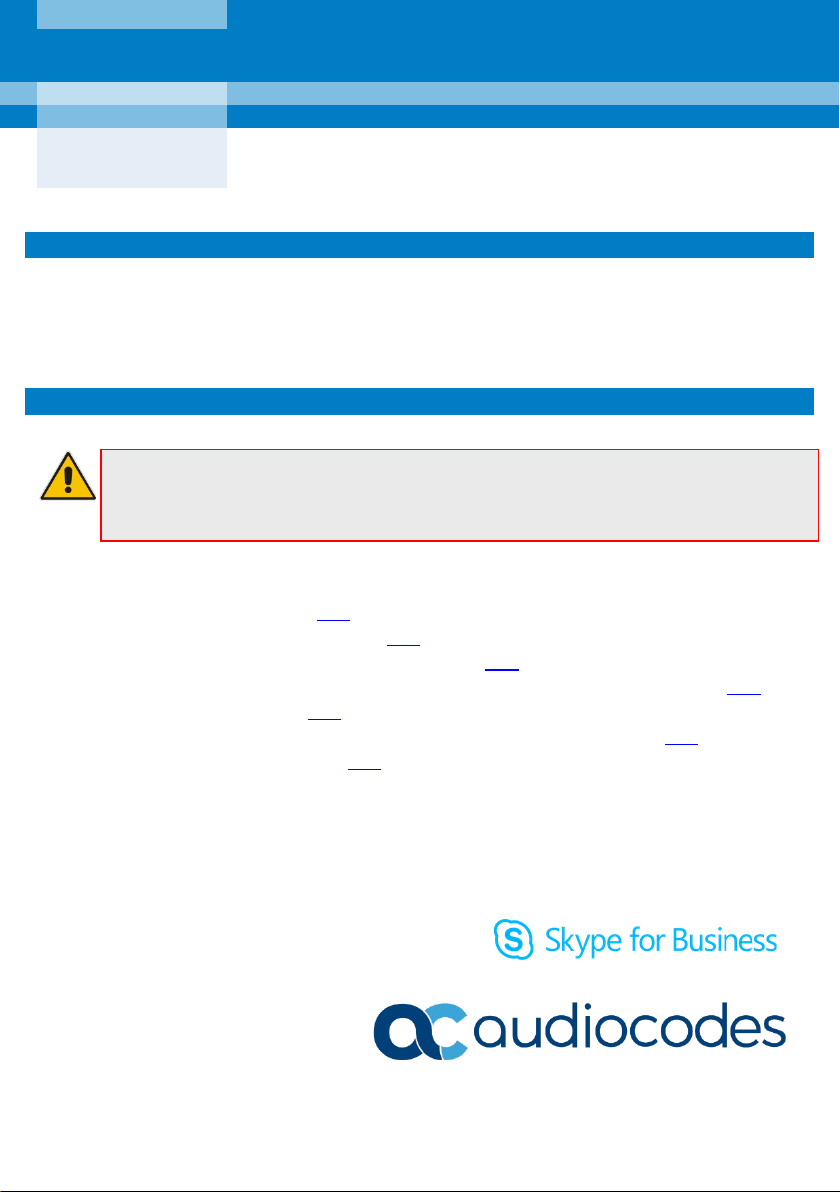
AudioCodes 450HD IP Phone Expansion Unit
1. Before Installing
Congratulations on purchasing the Expansion Module for your AudioCodes 450HD IP Phone!
Before installing it, make sure the following items are included in the shipped box:
Expansion Module
Kit containing five screws
2. Installation Process
• Disconnect the phone from the Power Supply / Power over Ethernet (PoE)
• Obtain a Philips screwdriver
To connect the Expansion Module to the 450HD phone:
Step 1: Prepare the two units – see here
Step 2: Remove the phone’s side panel – see here
Step 3: Connect the Expansion Module to the phone – see here
Step 4: Attach the panel removed from the phone in Step 3, to the Expansion Module – see here
Step 5: Secure the assembly – see here
Step 6: Install the Expansion Module's base stand and the phone's base stand - see here
Step 7: Mount the assembled unit - see here
1 | Page
Page 2
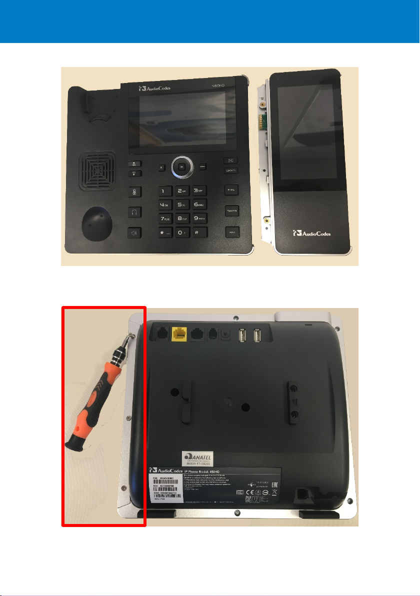
Step 1: Place the phone and the Expansion Module on a table alongside one other.
Step 2: Invert the phone on a surface that won’t scratch the screen such as a towel or printer paper.
Avoid inverting the phone on the surface of a desk. Then unscrew the three screws shown below in
order to remove the phone’s side panel:
2 | Page
Page 3

Step 3: Return the phone to an upright position. Remove the Expansion Module’s connector’s rubber
cover and then connect the Expansion Module to the phone. Note the connector and PEM direction.
3 | Page
Page 4

Step 4: Attach the panel that you removed from the phone in Step 3 to the side of the Expansion
Module, like this:
Step 5: Invert the assembled unit and secure the side panel by screwing in the three screws, like this:
Step 6: [Refer again to the figure above] Secure the connection of the two units by screwing in
these five screws.
4 | Page
Page 5

Step 7: With the assembly inverted, mount the phone on its dedicated base stand and the Expansion
Module on its dedicated base stand, like this:
Slots in the stands are slid onto rails on the units. The figure above shows the phone
mounted on the short edge of its ‘L’ shaped base stand, and the Expansion Module mounted on
the short edge of its ‘L’ shaped base stand. The long edge of the ‘L’ can alternatively be used per
user preference, depending on sources of glare in the office.
5 | Page
Page 6

Notice Information
Information contained in this document is believed to be accurate and reliable at the time of printing.
However, due to ongoing product improvements and revisions, AudioCodes cannot guarantee accuracy
of printed material after the Date Published nor can it accept responsibility for errors or omissions.
Updates to this document can be downloaded from https://www.audiocodes.com/library/technical-
documents.
This document is subject to change without notice.
Date Published: August-07-2018
LTRT-12828
6 | Page
 Loading...