

Audi AMB Service Manual
cardiagn.com
2005 Audi A4 Quattro
2005 Audi A4 Quattro
ENGINE 1.8 Liter 4-Cyl. 5V Turbo Engine Mechanical, Engine Code(s): AMB
ENGINE 1.8 Liter 4-Cyl. 5V Turbo Engine Mechanical, Engine Code(s): AMB
00 - GENERAL, TECHNICAL DATA
TECHNICAL DATA
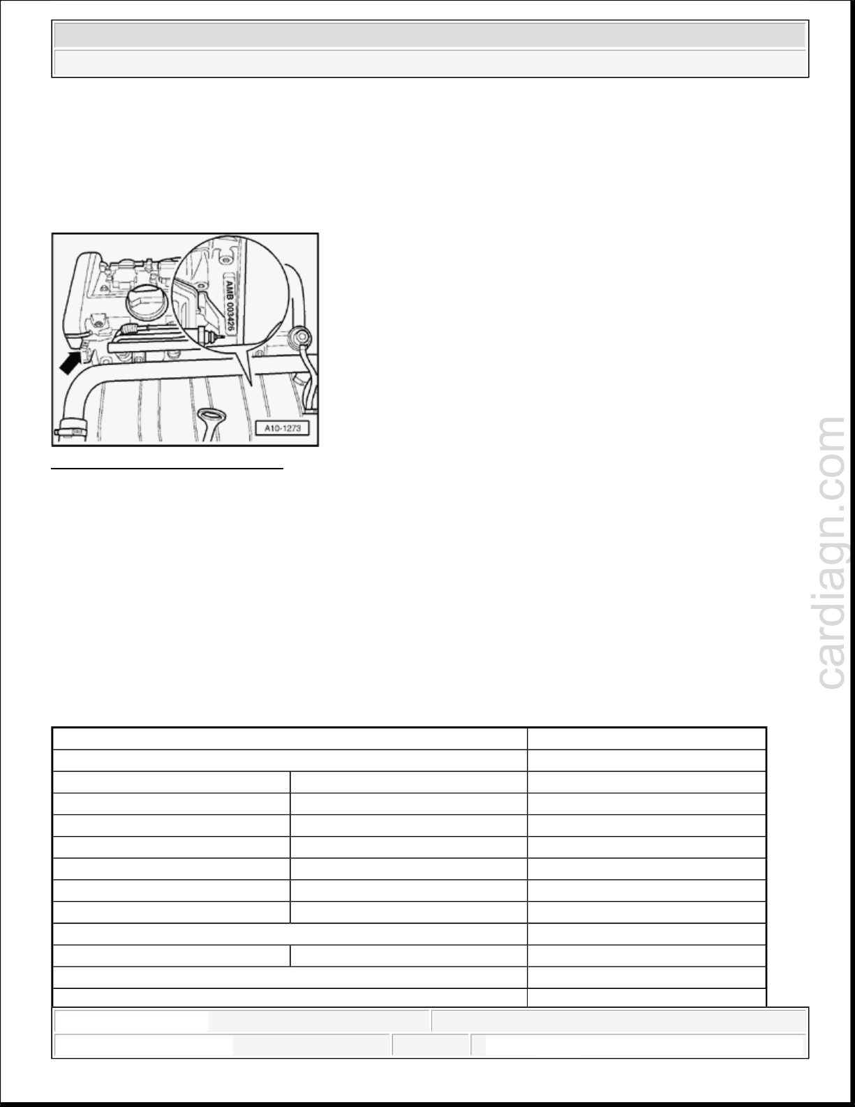
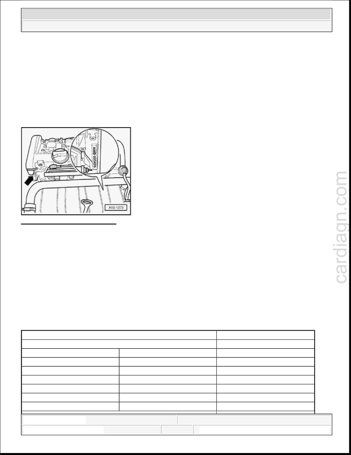
Engine number
Fig. 1: Locating Engine Number
Courtesy of VOLKSWAGEN UNITED STATES, INC.
The engine number ( "Engine code" and "Serial number" ) can be found on the rear left of the cylinder block.
Additionally there is a sticker on the toothed belt guard giving the "Engine code" and "Serial number".
The engine code is also given on the vehicle data sticker.
NOTE:
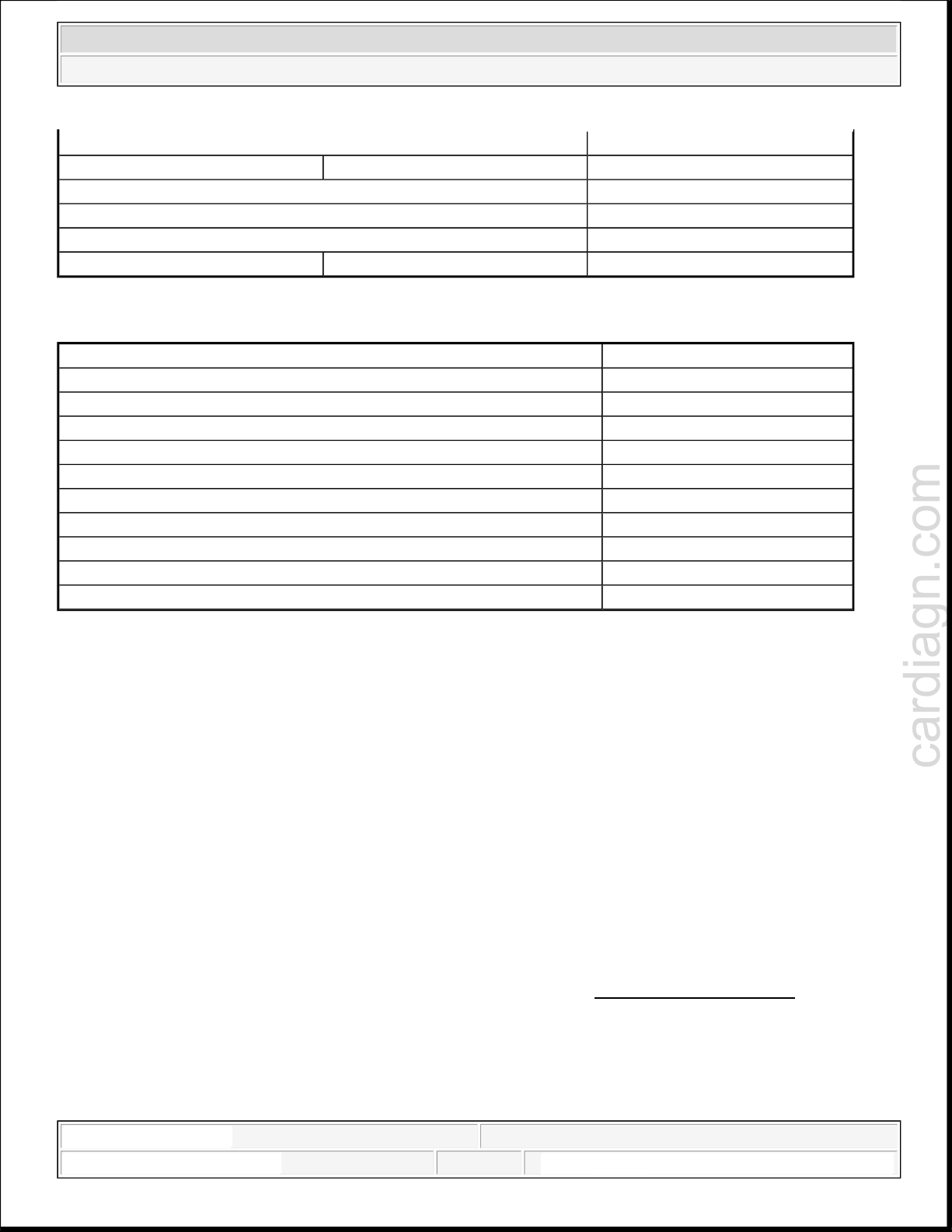
Engine data
Engine code AMB
Manufactured 08.01 -->
Capacity l 1.781
Power kW at RPM 125/5700
Torque Nm at RPM 210/1750 to 4600
Bore diameter mm 81.0
Stroke mm 86.4
Compression ratio 9.5
RON 95 * See note
Injection/ignition system Bosch Motronic
Knock control yes
On Board Diagnostic yes
The engine code is also stamped on the front lifting eye (visible when
engine cover panel is removed).
2:39:49 AM Page 1
2:39:52 AM Page 1
cardiagn.com
2005 Audi A4 Quattro
ENGINE 1.8 Liter 4-Cyl. 5V Turbo Engine Mechanical, Engine Code(s): AMB
Oxygen sensor control yes
Catalytic converter yes
Charging yes
*Standard unleaded RON 91 also permitted, however reduced power.
Engine code AMB
Exhaust gas recirculation no
Intake manifold change-over function no
Camshaft timing control yes
Secondary air system yes
Valve timing
at 1 mm valve lift and 0 mm valve clearance
Intake opens after TDC 18 °
Intake closes after BDC 28 °
Exhaust opens before BDC 28 °
Exhaust closes before TDC 8 °
2:39:49 AM Page 2
DTC INDEX
Bank 1, camshaft retardation adjustment
BEHIND
oxygen sensor control behind Three
2005 Audi A4 Quattro
cardiagn.com
2005 Audi A4 Quattro
DTC INDEX DTC Index - 1.8L (AMB Engine)
DTC INDEX DTC Index - 1.8L (AMB Engine)
DTC Index - 1.8L (AMB Engine)
D
IAGNOSTIC TROUBLE CODES (DTC) INDEX
DTC Index - 1.8L (AMB Engine)
SAE
C
ode
VAG
C
ode
Code Description Corrective Action
Bank 1, Camshaft adjustment
P0010 16394
m
alfunction
Camshafts and camshaft adjuster
r
emoving and installing
P0011 16395
P0012 16396
P0030 16414
P0031 16415
P0032 16416
P0036 16420
P0037 16421
Specification not reached
Bank 1, camshaft advance adjustment
S
pecification not reached
HO2S Heater Control Circuit, Bank 1
S
ensor 1
HO2S Heater Control Circuit Low,
B
ank 1 Sensor 1
HO2S Heater Control Circuit High,
B
ank 1 Sensor 1
HO2S Heater Control Circuit Bank, 1
S
ensor 2
HO2S Heater Control Circuit Low,
B
ank 1 Sensor 2
Check Valve -1- for camshaft
adjustment -N205-. See VALVE
1- FOR CAMSHAFT
ADJUSTMENT -N205-,
CHECKING .
C
heck oxygen sensor heater for
oxygen sensors before Three Way
Catalytic Converter (TWC). See
OXYGEN SENSOR (O2S)
HEATER -Z19- BEFORE
CATALYTIC CONVERTER,
CHECKING .
C
heck Oxygen Sensor (O2S) and
oxygen sensor control before Three
Way Catalytic Converter (TWC).
See HEATED OXYGEN
SENSOR (HO2S) -G39- AND
OXYGEN SENSOR
REGULATION BEFORE
CATALYTIC CONVERTER,
CHECKING .
C
heck oxygen sensor heater for
Oxygen Sensors (O2S) behind
Three Way Catalytic Converter
(TWC). See OXYGEN SENSOR
(O2S) HEATER 1 -Z29CATALYTIC CONVERTER,
CHECKING .
C
heck Oxygen Sensor (O2S) and
-
HO2S Heater Control Circuit High,
Bank 1 Sensor 2
11:32:47 PM Page 1
11:32:51 PM Page 1
Way Catalytic Converter (TWC).
See OXYGEN SENSORS AND
OXYGEN SENSOR

P0038 16422
Check Engine Coolant Temperature
O2 Sensor Circuit Slow Response, Bank
cardiagn.com
P0101 16485
P0102 16486
P0103 16487
P0106 16490
P0116 16500
P0117 16501
P0118 16502
P0121 16505
P0122 16506
P0123 16507
P0130 16514
P0133 16517
2005 Audi A4 Quattro
DTC INDEX DTC Index - 1.8L (AMB Engine)
Mass or Volume Air Flow Circuit
R
ange/Performance
Mass or Volume Air Flow Circuit Low
I
nput
Mass or Volume Air Flow Circuit High
I
nput
Manifold Absolute Pressure/Barometric
P
ressure Circuit Range/Performance
Engine Coolant Temperature Circuit
R
ange/Performance
Engine Coolant Temperature Circuit
L
ow
Engine Coolant Temperature Circuit
H
igh
Throttle/Pedal Position Sensor/Switch
"
A" Circuit Range/Performance
Throttle/Pedal Position Sensor/Switch
"
A" Circuit Low
Throttle/Pedal Position Sensor/Switch
"
A" Circuit High
O2 Sensor Circuit, Bank 1 Sensor 1
1 Sensor 1
O2 Sensor Heater Circuit, Bank 1
REGULATION BEHIND
CATALYTIC CONVERTER,
CHECKING .
C
heck Mass Air Flow (MAF)
Sensor -G70-. See MASS AIR
FLOW (MAF) SENSOR -G70-,
CHECKING .
C
heck intake air system for leaks
(false air). See INTAKE
SYSTEM, CHECKING FOR
LEAKS (FALSE AIR) .
S
ee appropriate SYSTEM WIRING
DIAGRAMS article.
Note
(ECT) Sensor -G62-. See E
COOLANT TEMPERATURE
(ECT) SENSOR -G62-,
CHECKING .
C
heck Throttle Valve Control
Module -J338-. See THROTTLE
VALVE CONTROL MODULE J338-, CHECKING .
C
heck oxygen sensor heater for
oxygen sensors before Three Way
Catalytic Converter (TWC). See
OXYGEN SENSOR (O2S)
HEATER -Z19- BEFORE
CATALYTIC CONVERTER,
CHECKING .
C
heck Oxygen Sensor (O2S) and
oxygen sensor control before Three
Way Catalytic Converter (TWC).
See HEATED OXYGEN
SENSOR (HO2S) -G39- AND
OXYGEN SENSOR
REGULATION BEFORE
CATALYTIC CONVERTER,
CHECKING .
NGINE
11:32:48 PM Page 2
BEHIND
oxygen sensor control behind Three
O2 Sensor Circuit High Voltage, Bank 1
O2 Sensor Circuit Slow Response, Bank
O2 Sensor Circuit No Activity Detected,
BEHIND
2005 Audi A4 Quattro
cardiagn.com
DTC INDEX DTC Index - 1.8L (AMB Engine)
P0135 16519
P0136 16520
P0137 16521
P0138 16522
P0139 16523
P0140 16524
P0141 16525
Sensor 1
O2 Sensor Circuit, Bank 1 Sensor 2
O2 Sensor Circuit Low Voltage, Bank 1
S
ensor 2
Sensor 2
1 Sensor 2
Bank 1 Sensor 2
O2 Sensor Heater Circuit, Bank 1
S
ensor 2
System Too Lean, Bank 1
C
heck oxygen sensor heater for
oxygen sensors before Three Way
Catalytic Converter (TWC). See
OXYGEN SENSOR (O2S)
HEATER -Z19- BEFORE
CATALYTIC CONVERTER,
CHECKING .
C
heck oxygen sensor heater for
Oxygen Sensors (O2S) behind
Three Way Catalytic Converter
(TWC). See OXYGEN SENSOR
(O2S) HEATER 1 -Z29CATALYTIC CONVERTER,
CHECKING .
C
heck Oxygen Sensor (O2S) and
Way Catalytic Converter (TWC).
S
ee OXYGEN SENSORS AND
OXYGEN SENSOR
REGULATION BEHIND
CATALYTIC CONVERTER,
CHECKING .
C
heck oxygen sensor heater for
Oxygen Sensors (O2S) behind
Three Way Catalytic Converter
(TWC). See OXYGEN SENSOR
(O2S) HEATER 1 -Z29CATALYTIC CONVERTER,
CHECKING .
P0171 16555
11:32:48 PM Page 3
C
heck fuel pressure regulator and
residual pressure. See SYSTEM
PRESSURE AND RESIDUAL
PRESSURE, CHECKING .
C
heck fuel injectors. See FUEL
INJECTORS, CHECKING .
C
heck intake air system for leaks
(false air). See INTAKE
SYSTEM, CHECKING FOR
LEAKS (FALSE AIR) .
C
heck Fuel Pump (FP). See FUEL
PUMP (FP), ELECTRICAL
TESTING for FWD and FUEL
PUMP (FP), ELECTRICAL
TESTING for AWD.
oxygen sensor control behind Three
2005 Audi A4 Quattro
cardiagn.com
DTC INDEX DTC Index - 1.8L (AMB Engine)
System Too Rich, Bank 1
C
heck exhaust system for proper
seal. See EXHAUST SYSTEM,
CHECKING FOR LEAKS .
C
heck Secondary Air Injection
(AIR) system for proper seal. See
SECONDARY AIR INJECTION
(AIR) SYSTEM, CHECKING
FOR PROPER SEAL .
C
heck vacuum lines for leaks
C
heck fuel pressure regulator and
residual pressure. See SYSTEM
PRESSURE AND RESIDUAL
PRESSURE, CHECKING .
C
heck fuel injectors. See FUEL
INJECTORS, CHECKING .
P0172 16556
P0201 16585 Injector Circuit/Open - Cylinder 1
P0202 16586 Injector Circuit/Open - Cylinder 2
P0203 16587 Injector Circuit/Open - Cylinder 3
P0204 16588 Injector Circuit/Open - Cylinder 4
P0221 16605
Throttle/Pedal Position Sensor/Switch
"B" Circuit Range/Performance
C
heck Oxygen Sensor (O2S) and
oxygen sensor control before Three
Way Catalytic Converter (TWC).
See HEATED OXYGEN
SENSOR (HO2S) -G39- AND
OXYGEN SENSOR
REGULATION BEFORE
CATALYTIC CONVERTER,
CHECKING .
C
heck Oxygen Sensor (O2S) and
Way Catalytic Converter (TWC).
S
ee OXYGEN SENSORS AND
OXYGEN SENSOR
REGULATION BEHIND
CATALYTIC CONVERTER,
CHECKING .
C
heck Evaporative Emission
(EVAP) Canister Purge Regulator
Valve -N80-. See CHECKING
EVAPORATIVE EMISSION
(EVAP) CANISTER PURGE
REGULATOR VALVE -N80- .
C
heck fuel injectors. See FUEL
INJECTORS, CHECKING .
Check Throttle Valve Control
11:32:48 PM Page 4

Check Engine Speed (RPM) Sensor
2005 Audi A4 Quattro
cardiagn.com
DTC INDEX DTC Index - 1.8L (AMB Engine)
P0222 16606
P0223 16607
Throttle/Pedal Position Sensor/Switch
"
B" Circuit Low
Throttle/Pedal Position Sensor/Switch
"
B" Circuit High
Fuel Pump Primary Circuit
P0230 16614
P0236 16620
P0237 16621
P0238 16622
P0243 16627
P0245 16629
P0246 16630
Charge air pressure sensor G31
i
mplausible signal
Charge air pressure sensor G31 signal
t
oo low
Charge air pressure sensor G31 signal
t
oo high
Wastegate bypass regulator valve N75
O
pen / Short to Ground
Wastegate bypass regulator valve N75
S
hort to Ground
Wastegate bypass regulator valve N75
S
hort to positive
P0261 16645 Cylinder 1 Injector Circuit Low
P0262 16646 Cylinder 1 Injector Circuit High
P0264 16648 Cylinder 2 Injector Circuit Low
P0265 16649 Cylinder 2 Injector Circuit High
P0267 16651 Cylinder 3 Injector Circuit Low
P0268 16652 Cylinder 3 Injector Circuit High
P0270 16654 Cylinder 4 Injector Circuit Low
P0271 16655 Cylinder 4 Injector Circuit High
Random/Multiple Cylinder Misfire
P0300 16684
P0301 16685
P0302 16686
P0303 16687
P0304 16688
P0321 16705
P0322 16706
D
etected
Cylinder 1 Misfire Detected
Cylinder 2 Misfire Detected
Cylinder 3 Misfire Detected
Cylinder 4 Misfire Detected
Ignition/Distributor Engine Speed Input
C
ircuit Range/Performance
Ignition/Distributor Engine Speed Input
C
ircuit No Signal
P0324 16708 Knock Control System Error
P0327 16711
Knock Sensor 1 Circuit Low, Bank 1 or
Single Sensor
Knock Sensor 1 Circuit High, Bank 1 or
Module -J338-. See T
HROTTLE
VALVE CONTROL MODULE J338-, CHECKING .
C
heck Fuel Pump (FP) Relay -J17-
and activation. See FUEL PUMP
(FP) RELAY -J17- AND
ACTIVATION, CHECKING .
C
heck Charge Air Pressure Sensor -
G31-. See CHARGE AIR
PRESSURE SENSOR -G31-,
CHECKING .
C
heck Wastegate Bypass Regulator
Valve -N75-. See WASTEGATE
BYPASS REGULATOR VALVE
-N75-, CHECKING .
C
heck fuel injectors. See FUEL
INJECTORS, CHECKING .
C
heck fuel injectors. See FUEL
INJECTORS, CHECKING .
C
heck ignition coils with power
output stages. See IGNITION
COILS WITH POWER
OUTPUT STAGES,
CHECKING .
-G28-. See ENGINE SPEED
(RPM) SENSOR -G28-,
CHECKING .
Check knock sensors. See CHECK
11:32:48 PM Page 5
system for function and proper seal.
2005 Audi A4 Quattro
cardiagn.com
DTC INDEX DTC Index - 1.8L (AMB Engine)
P0328 16712 Single Sensor KNOCK SENSORS .
P0332 16716 Knock Sensor 2 Circuit Low, Bank 2
P0333 16717 Knock Sensor 2 Circuit High, Bank 2
P0340 16724
Camshaft Position Sensor "A" Circuit,
B
ank 1 or Single Sensor
Camshaft Position Sensor "A" Circuit
C
P0341 16725
P0342 16726
P0343 16727
P0351 16735
P0352 16736
P0353 16737
P0354 16738
P0411 16795
R
ange/Performance, Bank 1 or Single
Sensor
Camshaft Position Sensor "A" Circuit
L
ow, Bank 1 or Single Sensor
Camshaft Position Sensor "A" Circuit
H
igh, Bank 1 or Single Sensor
Ignition Coil "A" Primary/Secondary
C
ircuit
Ignition Coil "B" Primary/Secondary
C
ircuit
Ignition Coil "C" Primary/Secondary
C
ircuit
Ignition Coil "D" Primary/Secondary
C
ircuit
Secondary Air Injection System
I
ncorrect Flow Detected
heck Camshaft Position (CMP)
sensor. See CAMSHAFT
POSITION (CMP) SENSOR G40-, CHECKING .
C
heck ignition coils with power
output stages. See IGNITION
COILS WITH POWER
OUTPUT STAGES,
CHECKING .
C
heck combination valves for
Secondary Air Injection (AIR)
P0413 16797
P0414 16798
P0418 16802
Secondary Air Injection solenoid valve
N
112 Open
Secondary Air Injection solenoid valve
N
112 Short circuit
Secondary Air Injection System Control
"
A" Circuit
Catalyst System, Bank1, Efficiency
B
elow Threshold
See C
OMBINATION VALVE
FOR SECONDARY AIR
INJECTION (AIR) SYSTEM,
CHECKING FUNCTION AND
FOR PROPER SEAL .
C
heck Secondary Air Injection
(AIR) Solenoid Valve -N112-. See
SECONDARY AIR INJECTION
(AIR) SOLENOID VALVE N112- CHECKING .
C
heck Secondary Air Injection
(AIR) Pump Relay -J299- and
activation. See SECONDARY
AIR INJECTION (AIR) PUMP
RELAY -J299- AND
ACTIVATION, CHECKING .
Check Oxygen Sensor (O2S) and
oxygen sensor control before Three
Way Catalytic Converter (TWC).
See HEATED OXYGEN
11:32:48 PM Page 6
oxygen sensor control behind Three
2005 Audi A4 Quattro
cardiagn.com
DTC INDEX DTC Index - 1.8L (AMB Engine)
SENSOR (HO2S) -G39- AND
OXYGEN SENSOR
REGULATION BEFORE
CATALYTIC CONVERTER,
CHECKING .
C
heck Oxygen Sensor (O2S) and
P0420 16804
P0440 16824
P0441 16825
P0442 16826
P0444 16828
P0445 16829
P0455 16839
P0456 16840
P0501 16885
P0506 16890
P0507 16891
P0560 16944
Way Catalytic Converter (TWC).
S
ee OXYGEN SENSORS AND
OXYGEN SENSOR
REGULATION BEHIND
CATALYTIC CONVERTER,
CHECKING .
C
heck catalytic conversion. See
TEST
-ID 01: CATALYTIC
CONVERTER .
Evaporative Emission System EVAP System
C
hecking Evaporative Emission (EVAP)
canister purge regulator valve -N80EVAP canister system checking for
proper seal
Evaporative Emissions (EVAP) system
diagnostic leak test
Note
Overview of component locations
Evaporative Emission System Incorrect
C
P
urge Flow
Evaporative Emission System Leak
D
etected (small leak)
Evaporative Emission System Purge
C
ontrol Valve Circuit Open
Evaporative Emission System Purge
C
ontrol Valve Circuit Shorted
Evaporative Emission System Leak
D
etected (large leak)
Evaporative Emission System Leak
D
etected (very small leak)
Vehicle Speed Sensor "A"
R
ange/Performance
Idle Air Control System RPM Lower
T
han Expected
Idle Air Control System RPM Higher
Than Expected
Voltage supply signal implausible
J220 - Motronic Engine Control Module
heck Evaporative Emission
(EVAP) Canister Purge Regulator
Valve -N80-. See CHECKING
EVAPORATIVE EMISSION
(EVAP) CANISTER PURGE
REGULATOR VALVE -N80- .
E
VAP canister system, check for
proper seal. See EVAP
CANISTER SYSTEM,
CHECKING FOR PROPER
SEAL .
C
heck speed signal. See SPEED
SIGNAL, CHECKING .
C
heck Throttle Valve Control
Module -J338-. See THROTTLE
VALVE CONTROL MODULE J338-, CHECKING .
(ECM)
11:32:48 PM Page 7
Internal Control Module Memory Check
ECM/PCM Power Relay Control Circuit
2005 Audi A4 Quattro
cardiagn.com
DTC INDEX DTC Index - 1.8L (AMB Engine)
P0562 16946
P0563 16947
P0571 16955
P0600 16984
P0601 16985
Voltage supply too low Motronic Engine Control Module (ECM)
pow
Voltage supply too high
er supply checking
Overview of component locations
Brake light switch F F - Brake Light Switch -F-
B
rake Light Switch -F- and Brake Pedal
Switch -F47F47 - Brake Pedal Switch
Brake Light Switch -F- and Brake Pedal
Switch -F47-
Data bus drive missing message
C
heck terminal resistance for CAN-
Bus. See TERMINAL
RESISTANCE FOR CAN-BUS,
CHECKING .
J220 - Motronic Engine Control Module
Sum Error
(
ECM) [2]
Replacing Engine Control Module
(ECM) (with metal anti-theft
housing)
Replacing Engine Control Module
(ECM) (without metal anti-theft
housing)
Control Module Programming
E
rror/Malfunction
P
rocedure to code Engine Control
Module (ECM):
P0602 16986
P0604 16988
P0605 16989
P0606 16990
P0685 17069
P0686 17070
Internal Control Module Random
A
ccess Memory (RAM) Error
Internal Control Module Read Only
M
emory (ROM) Error
ECM/PCM Processor
ECM/PCM Power Relay Control
C
ircuit/Open
Low
Motronic Fuel Injection and
Ignition (4-cylinder Turbo); See
ENCODING II ENGINE
CONTROL MODULE (ECM) .
J220 - Motronic Engine Control Module
(
ECM) [2]
Replacing Engine Control Module
(ECM) (with metal anti-theft
housing)
Replacing Engine Control Module
(ECM) (without metal anti-theft
housing)
C
heck voltage supply for Engine
Control Module (ECM). See
VOLTAGE SUPPLY FOR
ENGINE CONTROL MODULE
(ECM), CHECKING .
Check Motronic Engine Control
11:32:48 PM Page 8
ECM/PCM Power Relay Control Circuit
sensor 1, heating circuit short to
Overview of component locations Oxygen
sensor 2, heating circuit short to
and
oxygen sensor control behind Three
2005 Audi A4 Quattro
cardiagn.com
DTC INDEX DTC Index - 1.8L (AMB Engine)
P0687 17071
P0688 17072
P0704 17088
P1102 17510
P1103 17511
P1105 17513
P1111 17519
P1176 17584
High
Power supply relay J271 , load circuit
ope
n
Clutch Switch Input Circuit Malfunction
Bank 1 B+
Bank 1 -sensor 1, heating circuit, output
t
oo low
Bank 1 B+
Oxygen sensor control Bank 1 system
t
oo lean
Bank 1 oxygen sensor correction behind
c
at. control limit reached
Control limit reached
Module (ECM) Power Supply
R
elay -J271- and activation. See
CHECK MOTRONIC ENGINE
CONTROL MODULE (ECM)
POWER SUPPLY RELAY J271- AND ACTIVATION .
C
heck Clutch Vacuum Vent Valve
Switch -F36-. See CLUTCH
VACUUM VENT VALVE
SWITCH -F36-, CHECKING .
Z19 - Oxygen Sensor (O2S) Heater
Sensor (O2S) Heater -Z19- before
c
atalytic converter checking
Z29 - Oxygen Sensor (O2S) Heater 1
(
behind Three Way Catalytic Converter
(TWC))
Overview of component locations
Oxygen Sensor (O2S) Heater 1 -Z29behind catalytic converter checking
G39 - Heated Oxygen Sensor (HO2S)
H
eated Oxygen Sensor (HO2S) -G39oxygen sensor regulation before catalytic
c
onverter checking
Overview of component locations
C
heck Oxygen Sensor (O2S) and
oxygen sensor control before Three
Way Catalytic Converter (TWC).
See HEATED OXYGEN
SENSOR (HO2S) -G39- AND
OXYGEN SENSOR
REGULATION BEFORE
CATALYTIC CONVERTER,
CHECKING .
C
heck Oxygen Sensor (O2S) and
11:32:48 PM Page 9
Way Catalytic Converter (TWC).
S
ee OXYGEN SENSORS AND
OXYGEN SENSOR
REGULATION BEHIND
CATALYTIC CONVERTER,
CHECKING .
Check intake air system for leaks
(false air). See INTAKE
SYSTEM, CHECKING FOR
P1292 17700
Check Engine Coolant Temperature
cardiagn.com
P1293 17701
P1294 17702
P1296 17704
P2101 18533
P2122 18554
P2123 18555
P2127 18559
P2128 18560
P2138 18570
P2400 18832
P2401 18833
P2402 18834
P2403 18835
P2404 18836
2005 Audi A4 Quattro
DTC INDEX DTC Index - 1.8L (AMB Engine)
Malfunction in cooling system
Throttle Actuator Control Motor Circuit
R
ange/Performance
Throttle/Pedal Position Sensor/Switch
"
D" Circuit Low Input
Throttle/Pedal Position Sensor/Switch
"
D" Circuit High Input
Throttle/Pedal Position Sensor/Switch
"
E" Circuit Low Input
Throttle/Pedal Position Sensor/Switch
"
E" Circuit High Input
Throttle/Pedal Position Sensor/Switch
"
D" / "E" Voltage Correlation
Evaporative Emission System Leak
D
etection Pump Control Circuit/Open
Evaporative Emission System Leak
D
etection Pump Control Circuit Low
Evaporative Emission System Leak
D
etection Pump Control Circuit High
Evaporative Emission System Leak
D
etection Pump Sense Circuit/Open
Evaporative Emission System Leak
D
etection Pump Sense Circuit
Range/Performance
LEAKS (FALSE AIR) .
F265 - Map Controlled Engine Cooling
T
hermostat
Cooling system components, overview
(ECT) Sensor -G62-. See E
NGINE
COOLANT TEMPERATURE
(ECT) SENSOR -G62-,
CHECKING .
C
heck coolant regulator:
C
heck Throttle Valve Control
Module -J338-. See THROTTLE
VALVE CONTROL MODULE J338-, CHECKING .
C
heck Throttle Position (TP)
sensor. See THROTTLE
POSITION (TP) SENSOR,
CHECKING .
C
heck Leak detection pump (LDP)
-V144-. See LEAK DETECTION
PUMP (LDP) -V144-,
CHECKING .
E
VAP canister system, check for
proper seal. See EVAP
CANISTER SYSTEM,
CHECKING FOR PROPER
SEAL .
11:32:48 PM Page 10
cardiagn.com
2005 Audi A4 Quattro
2005 Audi A4 Quattro
ENGINE 1.8 Liter 4-Cyl. 5V Turbo Engine Mechanical, Engine Code(s): AMB
ENGINE 1.8 Liter 4-Cyl. 5V Turbo Engine Mechanical, Engine Code(s): AMB
1.8 Liter 4-Cyl. 5V Turbo Engine Mechanical, Engine Code(s): AMB
00 - GENERAL, TECHNICAL DATA
TECHNICAL DATA
Engine number
ENGINE
Fig. 1: Locating Engine Number
Courtesy of VOLKSWAGEN UNITED STATES, INC.
The engine number ( "Engine code" and "Serial number" ) can be found on the rear left of the cylinder block.
Additionally there is a sticker on the toothed belt guard giving the "Engine code" and "Serial number".
The engine code is also given on the vehicle data sticker.
NOTE:
Engine data
Engine code AMB
Manufactured 08.01 -->
Capacity l 1.781
Power kW at RPM 125/5700
Torque Nm at RPM 210/1750 to 4600
Bore diameter mm 81.0
Stroke mm 86.4
Compression ratio 9.5
RON 95 * See note
The engine code is also stamped on the front lifting eye (visible when
engine cover panel is removed).
1:00:55 AM Page 1
1:01:41 AM Page 1
cardiagn.com
2005 Audi A4 Quattro
ENGINE 1.8 Liter 4-Cyl. 5V Turbo Engine Mechanical, Engine Code(s): AMB
Injection/ignition system Bosch Motronic
Knock control yes
On Board Diagnostic yes
Oxygen sensor control yes
Catalytic converter yes
Charging yes
*Standard unleaded RON 91 also permitted, however reduced power.
Engine code AMB
Exhaust gas recirculation no
Intake manifold change-over function no
Camshaft timing control yes
Secondary air system yes
Valve timing
at 1 mm valve lift and 0 mm valve clearance
Intake opens after TDC 18 °
Intake closes after BDC 28 °
Exhaust opens before BDC 28 °
Exhaust closes before TDC 8 °
10 - ENGINE - ASSEMBLY
ENGINE, REMOVING AND INSTALLING
Engine, removing and installing
CAUTION: Before beginning repairs on the electrical system:
Obtain the anti-theft radio security code.
Switch the ignition off.
Disconnect the battery Ground (GND) strap.
On vehicles equipped with Audi Telematics by OnStar, switch-off the
emergency (back-up) battery for the Telematic/Telephone Control Module
prior to disconnecting vehicle battery --> 91 - COMMUNICATION
After reconnecting vehicle battery, re-code and check operation of antitheft radio. Also check operation of clock and power windows according
to Repair Article and/or Owners Manual.
1:00:55 AM Page 2
cardiagn.com
ENGINE 1.8 Liter 4-Cyl. 5V Turbo Engine Mechanical, Engine Code(s): AMB
After reconnecting vehicle battery on vehicles equipped with Audi
Telematics by OnStar, switch-on the emergency (back-up) battery for the
Telematic/Telephone Control Module --> 91
Engine, removing and installing
2005 Audi A4 Quattro
- COMMUNICATION
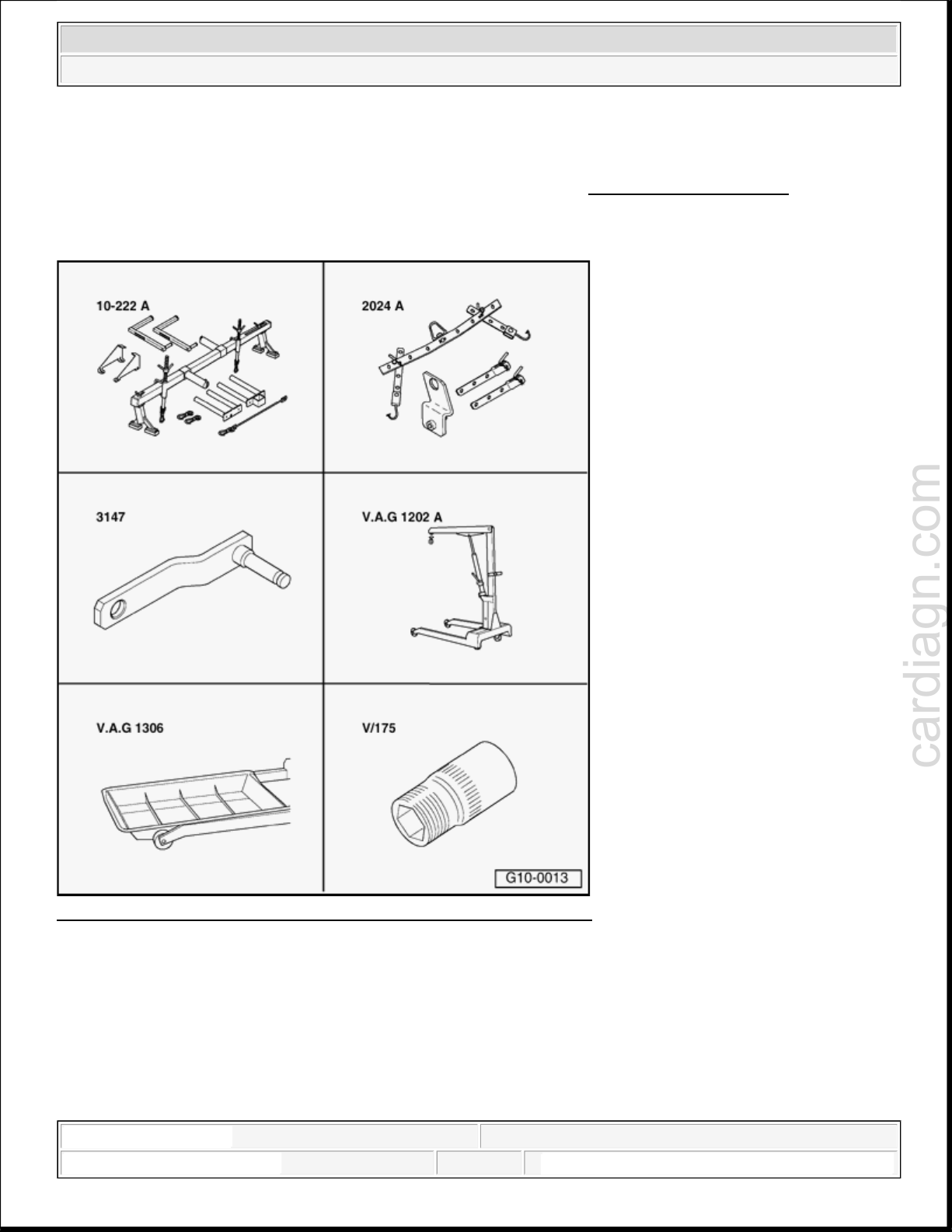
Fig. 2: Identifying Special Tools - Engine, Removing And Installing
Courtesy of VOLKSWAGEN UNITED STATES, INC.
Special tools, testers and auxiliary items required
Support bar 10-222A
Lifting tackle 2024A
Special tool 3147
Workshop crane VAG1202A
1:00:55 AM Page 3
cardiagn.com
2005 Audi A4 Quattro
ENGINE 1.8 Liter 4-Cyl. 5V Turbo Engine Mechanical, Engine Code(s): AMB
Drip tray VAG1306
Socket attachment 15 mm A/F Matra V/175
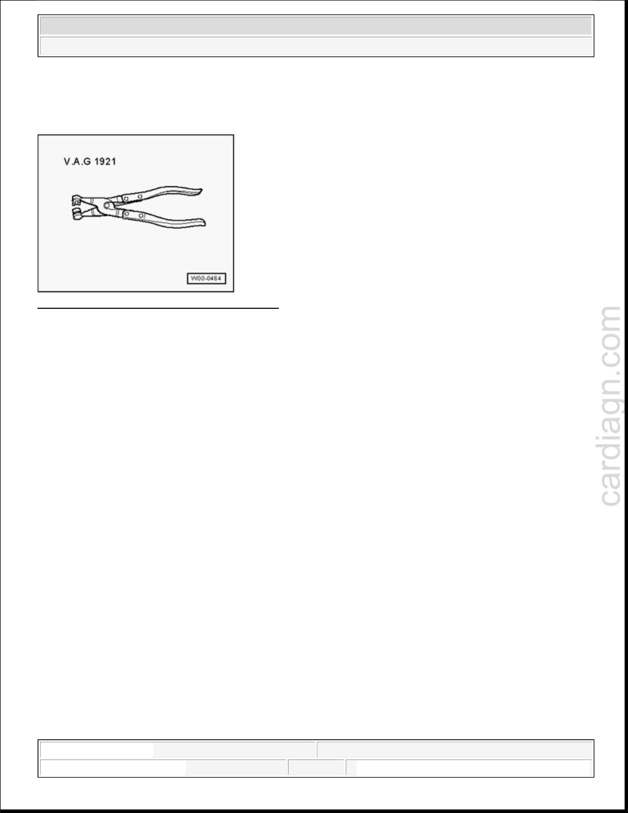
Fig. 3: Identifying Hose Clip Pliers VAG 1921
Courtesy of VOLKSWAGEN UNITED STATES, INC.
Hose clip pliers VAG5024
Engine, removing
NOTE:
All cable ties unfastened or cut when removing engine are to be
reattached in same position during installation.
Engine must be removed without transmission from front of vehicle.
Catch drained coolant in a clean container for re-use or disposal.
Vehicles with automatic transmission
Move selector lever to position N.
All models
Obtain radio anti-theft code for vehicles with encoded radio.
1:00:55 AM Page 4
cardiagn.com
2005 Audi A4 Quattro
ENGINE 1.8 Liter 4-Cyl. 5V Turbo Engine Mechanical, Engine Code(s): AMB
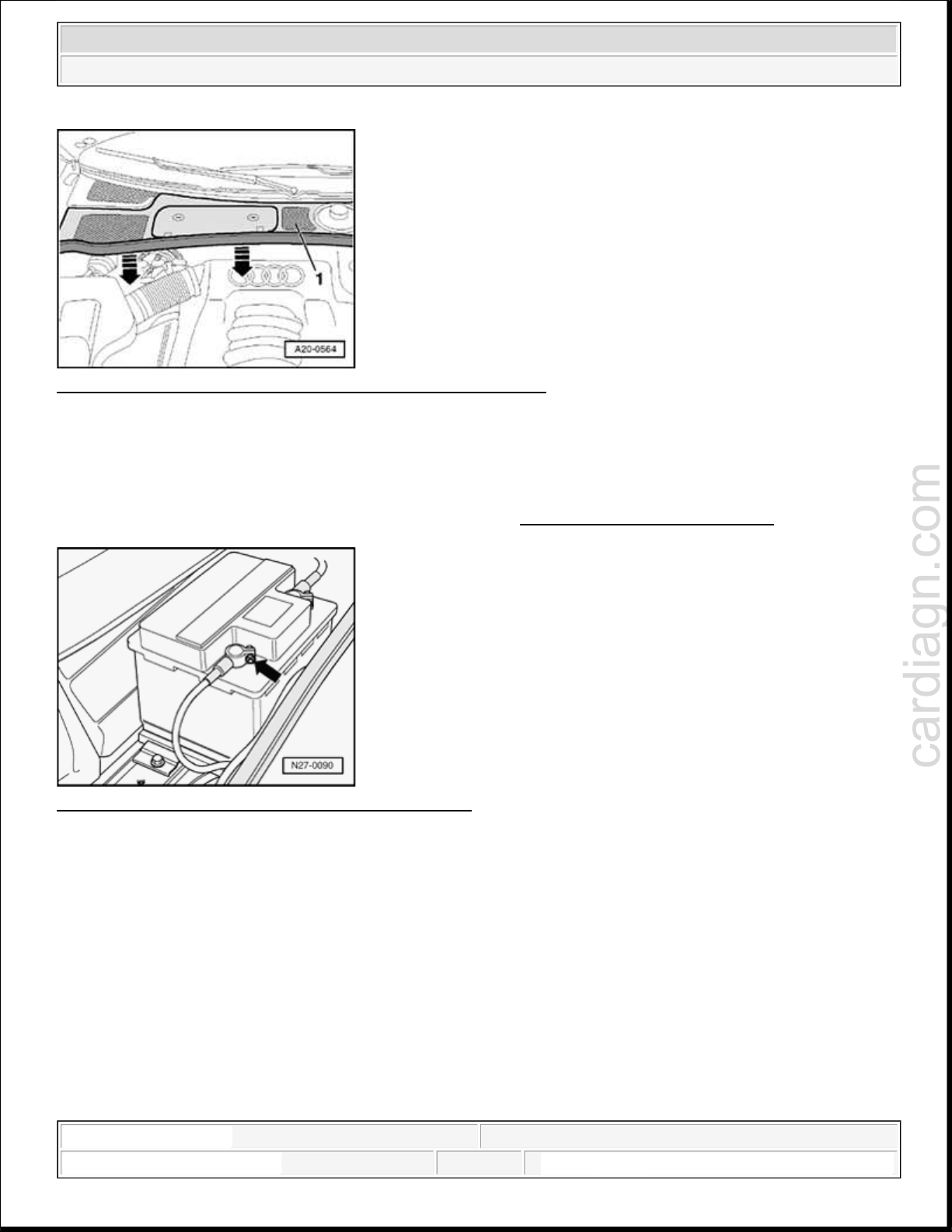
Fig. 4: Removing Rubber Seal From Plenum Chamber Cover
Courtesy of VOLKSWAGEN UNITED STATES, INC.
Remove rubber seal from plenum chamber cover in direction of - arrow -.
Pull plenum chamber cover - 1 - toward front and remove.
See Caution before beginning repairs on electrical system --> Engine, removing and installing
Fig. 5: Identifying Battery Ground (GND) Terminal
Courtesy of VOLKSWAGEN UNITED STATES, INC.
With ignition switched off, disconnect battery Ground strap - arrow -.
Use screwdriver to pry off caps - 3 - from wiper arms.
1:00:55 AM Page 5
cardiagn.com
2005 Audi A4 Quattro
ENGINE 1.8 Liter 4-Cyl. 5V Turbo Engine Mechanical, Engine Code(s): AMB
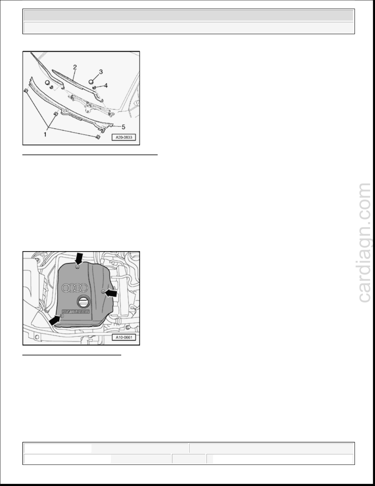
Fig. 6: Removing Securing Clips And Cowl
Courtesy of VOLKSWAGEN UNITED STATES, INC.
Loosen hex nuts - 4 - by a few turns.
Tilt wiper arm - 2 - slightly to remove it from wiper shaft.
Remove hex nuts completely and remove wiper arms.
Pull off securing clips - 1 - and remove panel trim.
CAUTION: Hot steam can escape when cap on expansion tank is opened. Cover cap
with cloth and open carefully.
Fig. 7: Removing Engine Cover
Courtesy of VOLKSWAGEN UNITED STATES, INC.
Remove engine cover - arrows -.
1:00:55 AM Page 6
cardiagn.com
2005 Audi A4 Quattro
ENGINE 1.8 Liter 4-Cyl. 5V Turbo Engine Mechanical, Engine Code(s): AMB
Fig. 8: Air Cleaner Cover
Courtesy of VOLKSWAGEN UNITED STATES, INC.
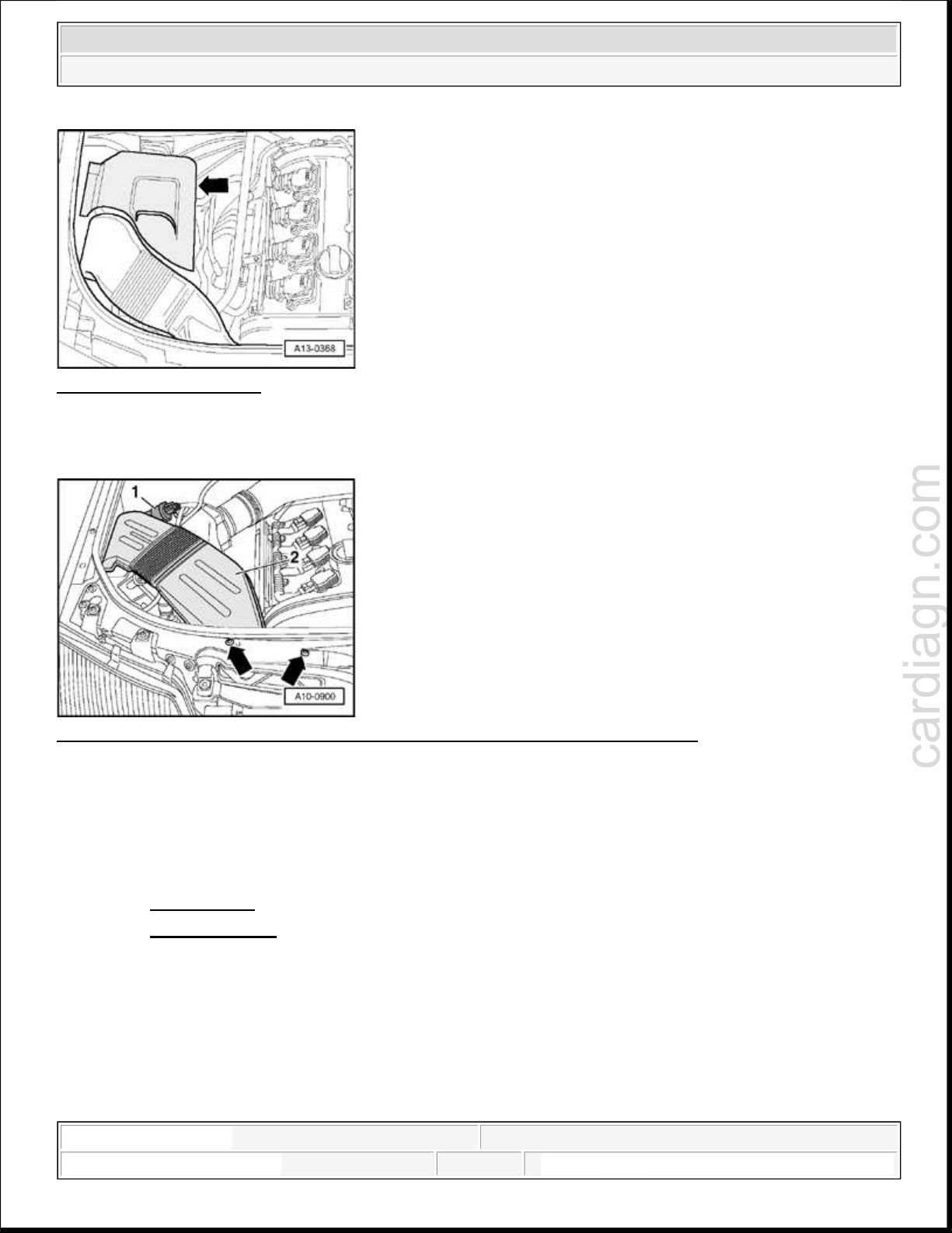
Remove air cleaner cover - arrow -.
Fig. 9: Evaporative Emission Canister Purge Regulator Valve N80 And Air Duct
Courtesy of VOLKSWAGEN UNITED STATES, INC.
Remove bolts - arrows -.
Disengage EVAP canister purge regulator valve N80 - 1 - from air duct - 2 -.
Remove both screws - arrows - for air duct - 2 -.
Remove front bumper: -->
63 BUMPER
63 - BUMPERS for CABRIOLET
Vehicles with auxiliary heater
1:00:55 AM Page 7
cardiagn.com
2005 Audi A4 Quattro
ENGINE 1.8 Liter 4-Cyl. 5V Turbo Engine Mechanical, Engine Code(s): AMB
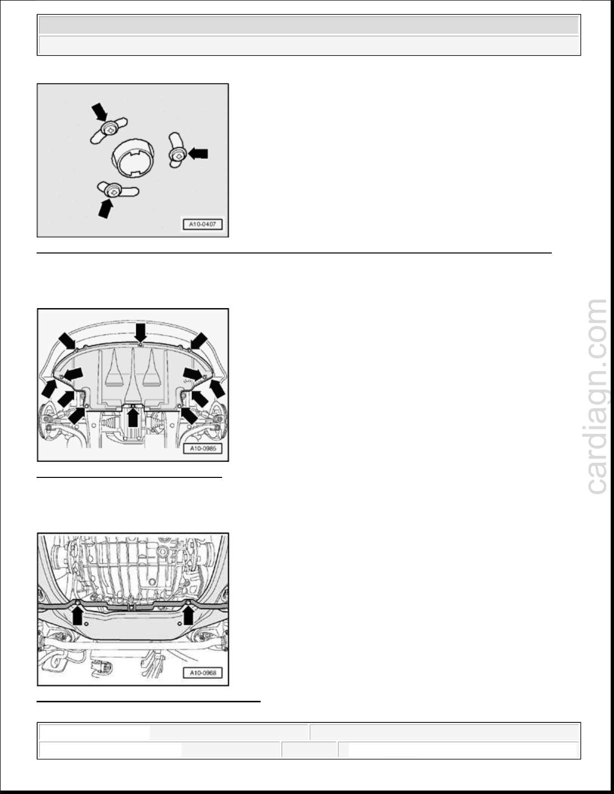
Fig. 10: Removing Bolts Securing Exhaust Pipe Of Auxiliary/Additional Heater To Sound Insulation
Courtesy of VOLKSWAGEN UNITED STATES, INC.
Remove bolts - arrows - securing exhaust pipe of auxiliary/additional heater to sound insulation.
Fig. 11: Removing Sound Insulation
Courtesy of VOLKSWAGEN UNITED STATES, INC.
Remove sound insulation - arrows -.
Fig. 12: Unbolting Sound Insulation Holder
Courtesy of VOLKSWAGEN UNITED STATES, INC.
1:00:55 AM Page 8
cardiagn.com
2005 Audi A4 Quattro
ENGINE 1.8 Liter 4-Cyl. 5V Turbo Engine Mechanical, Engine Code(s): AMB
Unbolt sound insulation holder.
Fig. 13: Removing Air Duct In Front Of Charge Air Cooler
Courtesy of VOLKSWAGEN UNITED STATES, INC.
Remove air duct in front of charge air cooler - arrows -.
Place drip tray VAG1306 under engine.
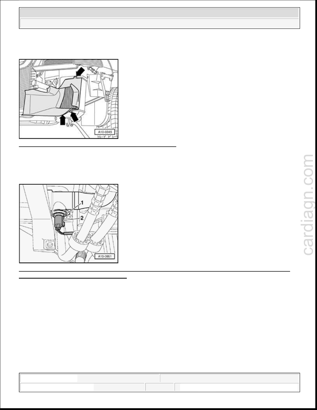
Fig. 14: Pulling Retaining Clip For Engine Coolant Temperature (ECT) Sensor G2 Off Lower Coolant
Hose And Drain Coolant From Radiator
Courtesy of VOLKSWAGEN UNITED STATES, INC.
Pull retaining clip - 1 - for Engine Coolant Temperature (ECT) sensor G2 - 2 - off lower coolant hose and
drain coolant from radiator.
Remove lower coolant hose from radiator.
1:00:55 AM Page 9
cardiagn.com
2005 Audi A4 Quattro
ENGINE 1.8 Liter 4-Cyl. 5V Turbo Engine Mechanical, Engine Code(s): AMB
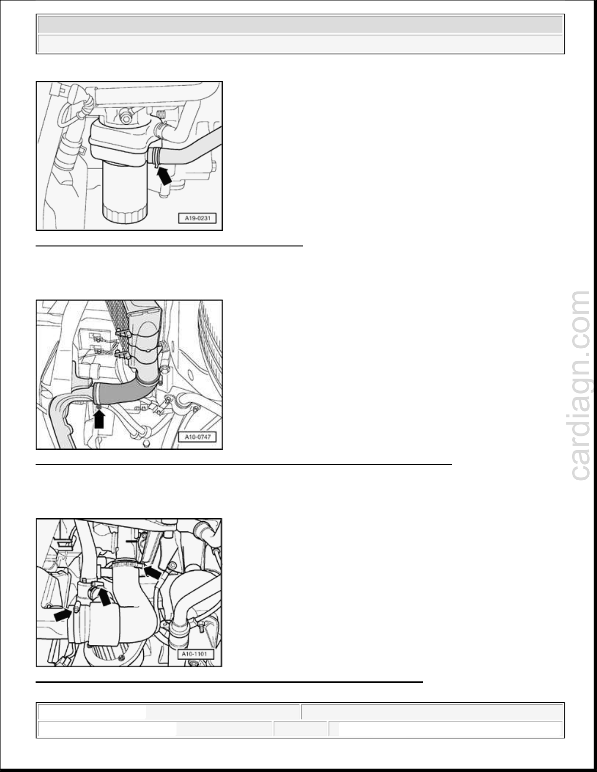
Fig. 15: Disconnecting Coolant Hose From Oil Cooler
Courtesy of VOLKSWAGEN UNITED STATES, INC.
Disconnect coolant hose from oil cooler - arrow - and drain remaining coolant.
Fig. 16: Removing Air Hose To Charge Air Cooler At Bottom Left Of Lock Carrier
Courtesy of VOLKSWAGEN UNITED STATES, INC.
Remove air hose - arrow - to charge air cooler at bottom left of lock carrier.
Fig. 17: Removing Lower Air Hose Between Turbocharger And Lock Carrier
Courtesy of VOLKSWAGEN UNITED STATES, INC.
1:00:55 AM Page 10
g
cardiagn.com
2005 Audi A4 Quattro
ENGINE 1.8 Liter 4-Cyl. 5V Turbo Engine Mechanical, Engine Code(s): AMB
Remove lower air hose - arrow - between turbocharger and lock carrier.
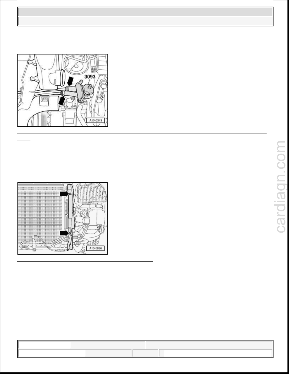
Fig. 18: Using 3093 To Clamp Off Inlet And Outlet Pipe Of Cooling Coil For Power Steering Hydraulic
Fluid
Courtesy of VOLKSWAGEN UNITED STATES, INC.
Use 3093 to clamp off inlet and outlet pipe of cooling coil for power steering hydraulic fluid.
Place suitable container under hoses.
Disconnect hoses from cooling coil.
Fig. 19: Removing Air Ducts On Left/Right Of Radiator
Courtesy of VOLKSWAGEN UNITED STATES, INC.
Remove air ducts on left and ri
ht of radiator - arrows -.
1:00:55 AM Page 11
cardiagn.com
2005 Audi A4 Quattro
ENGINE 1.8 Liter 4-Cyl. 5V Turbo Engine Mechanical, Engine Code(s): AMB
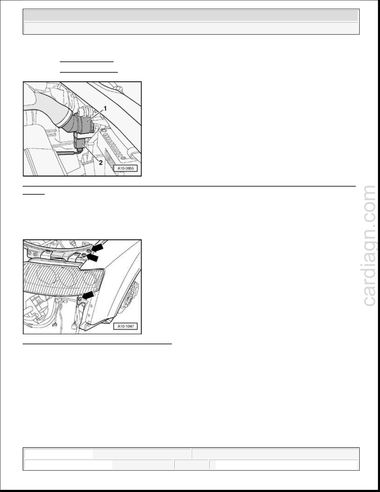
Fig. 20: Disconnecting Connector From A/C Pressure Switch F129 & Ambient Temperature Sensor
Courtesy of VOLKSWAGEN UNITED STATES, INC.
Disconnect connector - 1 - from A/C pressure switch F129.
Disconnect connector - 2 - from ambient temperature sensor.
Move both wires clear.
CAUTION: Air conditioner refrigerant circuit must not be opened.
Unbolt condenser - arrows - from radiator.
NOTE:
To prevent damage to condenser and refrigerant lines/hoses ensure that
lines and hoses are not stretched, kinked or bent.
Carefully swivel condenser downward and set down.
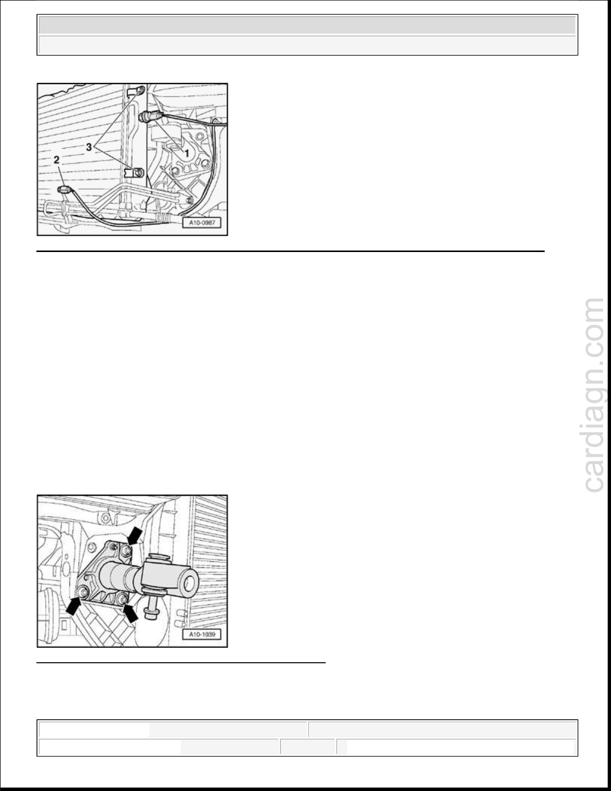
Fig. 21: Removing Impact Absorber Bolts On Left/Right
Courtesy of VOLKSWAGEN UNITED STATES, INC.
Remove impact absorber bolts on left and right - arrows -.
Remove hood lock cable from lock carrier: -->
1:00:55 AM Page 12
cardiagn.com
2005 Audi A4 Quattro
ENGINE 1.8 Liter 4-Cyl. 5V Turbo Engine Mechanical, Engine Code(s): AMB
55 HOOD, LIDS
55 - HOOD, LIDS for CABRIOLET
Fig. 22: Removing Top Coolant Hose From Radiator & Disconnecting Connectors For Left/Right Airbag
Sensor
Courtesy of VOLKSWAGEN UNITED STATES, INC.
Remove top coolant hose from radiator - 1 -.
Disconnect connectors - 2 - for left and right airbag sensor.
Fig. 23: Unbolting Lock Carrier On Left/Right
Courtesy of VOLKSWAGEN UNITED STATES, INC.
Unbolt lock carrier on left and right - arrows -.
NOTE:
A second technician is required to remove the lock carrier.
Place lock carrier in a secure position.
Remove lock carrier.
Vehicles with automatic transmission
1:00:55 AM Page 13
cardiagn.com
2005 Audi A4 Quattro
ENGINE 1.8 Liter 4-Cyl. 5V Turbo Engine Mechanical, Engine Code(s): AMB
NOTE:
Observe the rules for cleanliness when working on an automatic
transmission:
-->
37 - AUTOMATIC TRANSMISSION - CONTROLS, HOUSING for 5 SPD.
37 - AUTOMATIC TRANSMISSION - CONTROLS, HOUSING for 5 SPD.
37 CONTROLS, HOUSING for AUTOMATIC TRANSMISSION 09L,
Place drip tray underneath.
AUTOMATIC TRANSMISSION 01V
AUTOMATIC TRANSMISSION 01V FRONT AND ALL WHEEL DRIVE INTERNAL COMPONENTS, SERVICING
FOUR-WHEEL DRIVE
Fig. 24: Disconnecting ATF Lines
Courtesy of VOLKSWAGEN UNITED STATES, INC.
Disconnect ATF lines - arrows -.
Unbolt bracket for ATF lines on left of engine.
Vehicles up to 06.03
CAUTION: Fuel system is under pressure! Before opening system, place rags around
the connection point. Then release pressure by carefully loosening
connection.
1:00:55 AM Page 14
cardiagn.com
2005 Audi A4 Quattro
ENGINE 1.8 Liter 4-Cyl. 5V Turbo Engine Mechanical, Engine Code(s): AMB
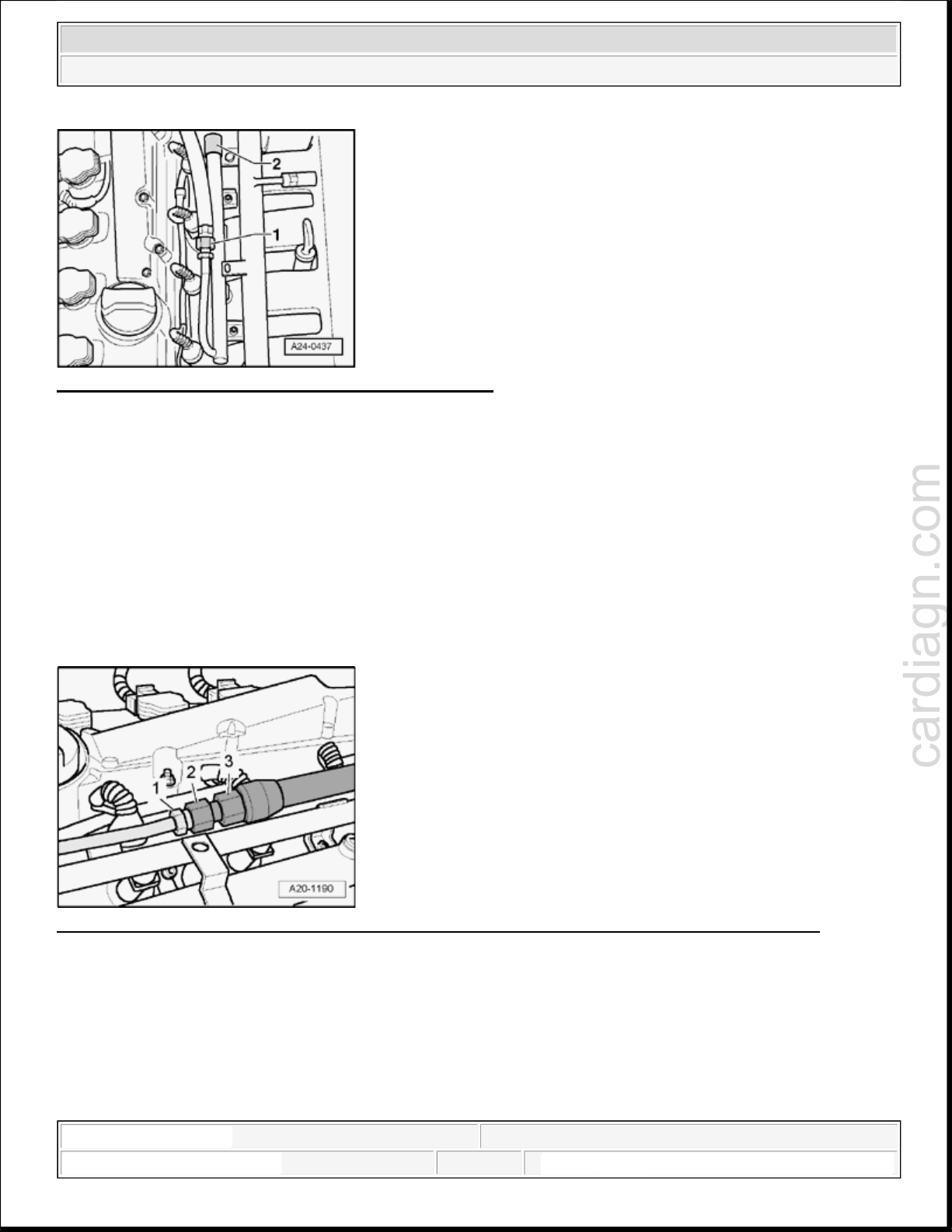
Fig. 25: Disconnecting Fuel Supply Line And Set Aside
Courtesy of VOLKSWAGEN UNITED STATES, INC.
Disconnect fuel supply line - 1 - and set aside.
NOTE:
Disregard - 2 -.
Vehicles as of 07.03
CAUTION: Fuel system is under pressure! Before opening system, place rags around
the connection point. Then release pressure by carefully loosening
connection.
Fig. 26: Counterholding Using An Open
-End Wrench At Each Hex Head & Unscrew Union Nut
Courtesy of VOLKSWAGEN UNITED STATES, INC.
Unscrew fuel hose from connection on fuel rail pipe. To do so, counterhold using an open-end wrench at
each hex head - 1 - and - 3 - and unscrew union nut - 2 -.
All
Seal off line so that no dirt will get into fuel system.
1:00:55 AM Page 15
cardiagn.com
2005 Audi A4 Quattro
ENGINE 1.8 Liter 4-Cyl. 5V Turbo Engine Mechanical, Engine Code(s): AMB
CAUTION: Fuel system is under pressure! Before opening system, place rags around
the connection point. Then release pressure by carefully loosening
connection.
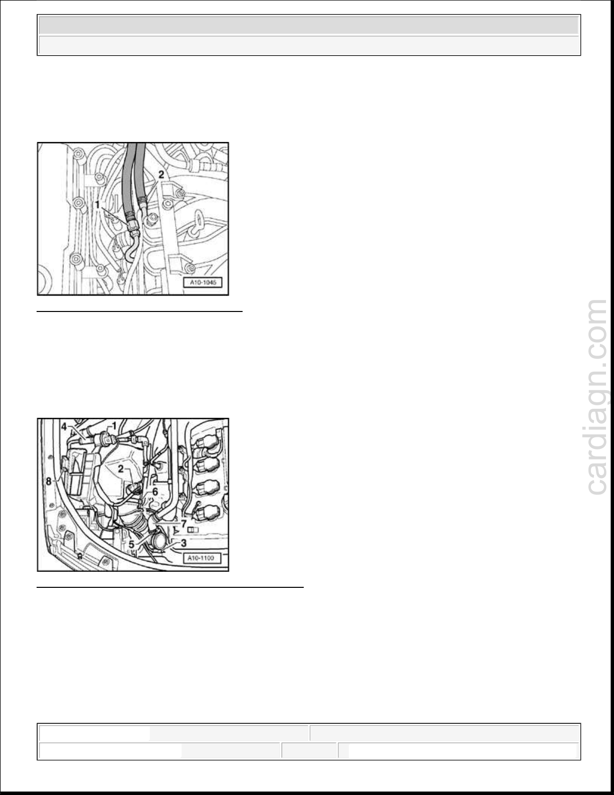
Fig. 27: Disconnecting Fuel Supply Line
Courtesy of VOLKSWAGEN UNITED STATES, INC.
Disconnect fuel supply line.
Seal off line so that no dirt can enter fuel system.
Unbolt Ground connection from plenum chamber.
Remove vacuum line to brake servo from plenum chamber.
Fig. 28: Disconnect Wires/Unplug Connectors From
Courtesy of VOLKSWAGEN UNITED STATES, INC.
Disconnect wires/unplug connectors from:
1. EVAP canister purge regulator valve
2. Mass air flow sensor
3. Wastegate bypass regulator valve N75
Disconnect hoses 4...7.
1:00:55 AM Page 16
V
cardiagn.com
2005 Audi A4 Quattro
ENGINE 1.8 Liter 4-Cyl. 5V Turbo Engine Mechanical, Engine Code(s): AMB
Disconnect hose to secondary air injection pump motor - 8 -.
Move wires clear.
Unbolt air cleaner housing - 9 -.
Remove air cleaner.
NOTE:
acuum pipe to secondary air combination valve is clipped to underside of
air intake hose.
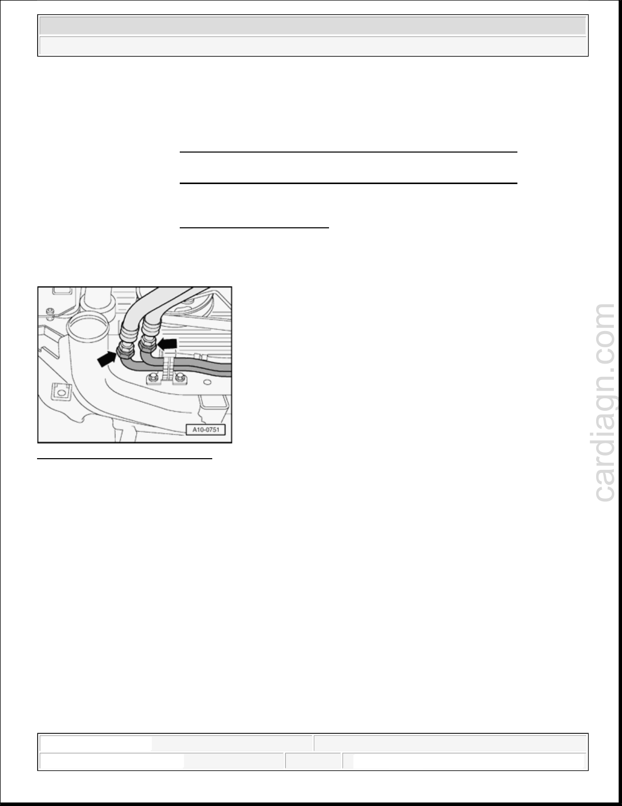
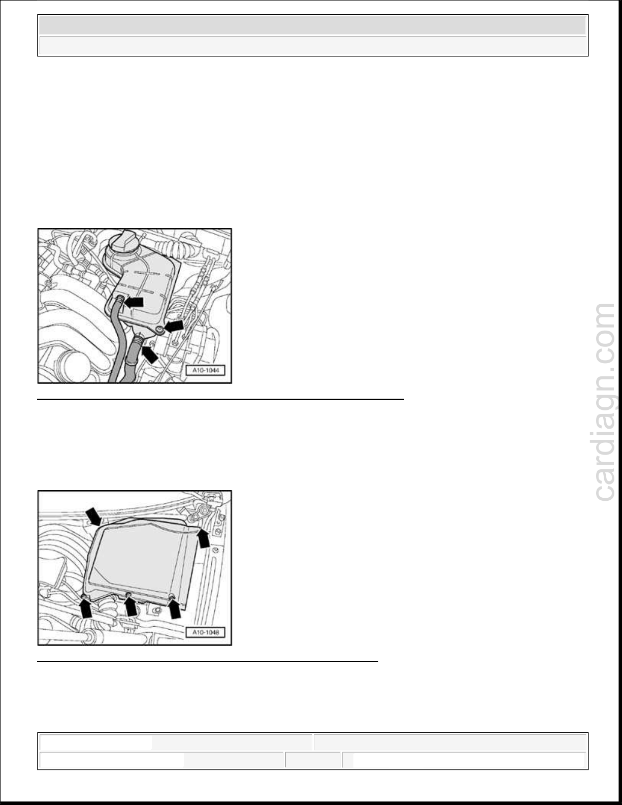
Fig. 29: Removing Both Coolant Hoses From Coolant Expansion Tank
Courtesy of VOLKSWAGEN UNITED STATES, INC.
Remove both coolant hoses from coolant expansion tank.
Unbolt coolant expansion tank.
Lift coolant expansion tank slightly at bolt side and pull it out of catch on plenum chamber side.
Fig. 30: Unbolting Cover Of Electronics Box In Plenum Chamber
Courtesy of VOLKSWAGEN UNITED STATES, INC.
Unbolt cover of electronics box in plenum chamber.
1:00:55 AM Page 17
cardiagn.com
2005 Audi A4 Quattro
ENGINE 1.8 Liter 4-Cyl. 5V Turbo Engine Mechanical, Engine Code(s): AMB
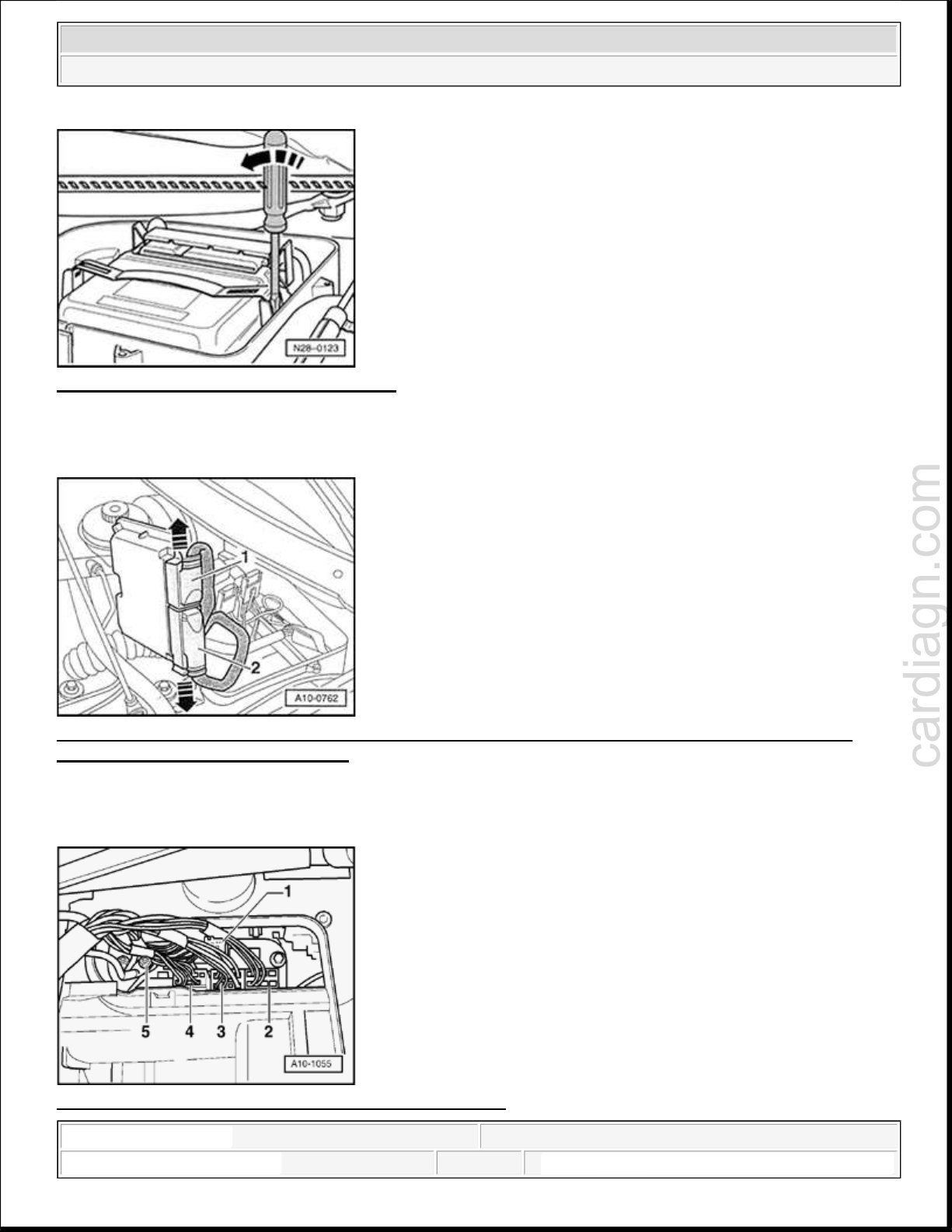
Fig. 31: Removing Engine Control Module
Courtesy of VOLKSWAGEN UNITED STATES, INC.
Carefully pry off retainer bar with screwdriver - arrow -.
Fig. 32: Disengaging Electrical Connector Retainers And Disconnecting Electrical Connectors From
Engine Control Module (ECM) J623
Courtesy of VOLKSWAGEN UNITED STATES, INC.
Release catches - arrows - and disconnect control module connectors - 1 - and - 2 -.
Fig. 33: Disconnecting Connectors From Connector Rail
1:00:56 AM Page 18
 Loading...