

Audi Air conditioning 2003 A8 Workshop Manual
Protected by copyright. Copying for private or commercial purposes, in part or in whole, is not
permitted unless authorised by AUDI AG. AUDI AG does not guarantee or accept any liability
with respect to the correctness of information in this document. Copyright by AUDI AG.
Service
Workshop Manual
Audi A8 2003 ➤
Air conditioning
Edition 09.2010
Service Department. Technical Information

Protected by copyright. Copying for private or commercial purposes, in part or in whole, is not
permitted unless authorised by AUDI AG. AUDI AG does not guarantee or accept any liability
with respect to the correctness of information in this document. Copyright by AUDI AG.
Service
List of Workshop Manual Repair GroupsList of Workshop Manual
Repair GroupsList of Workshop Manual Repair Groups
Re pa ir G ro up
87 - Air conditioning system
Technical information should always be available to the foremen and mechanics, because their
careful and constant adherence to the instructions is essential to ensure vehicle road-worthiness and
safety. In addition, the normal basic safety precautions for working on motor vehicles must, as a
matter of course, be observed.
All rights reserved.
No reproduction without prior agreement from publisher.
Copyright © 2010 Audi AG, Ingolstadt A0051005620

Protected by copyright. Copying for private or commercial purposes, in part or in whole, is not
permitted unless authorised by AUDI AG. AUDI AG does not guarantee or accept any liability
with respect to the correctness of information in this document. Copyright by AUDI AG.
Audi A8 2003 ➤
Air conditioning - Edition 09.2010
Contents
87 - Air conditioning system . . . . . . . . . . . . . . . . . . . . . . . . . . . . . . . . . . . . . . . . . . . . 1
1 Safety precautions when working on vehicles fitted with an air conditioner and for handling
refrigerant . . . . . . . . . . . . . . . . . . . . . . . . . . . . . . . . . . . . . . . . . . . . . . . . . . . . . . . . . . . . . . 1
1.1 Safety precautions . . . . . . . . . . . . . . . . . . . . . . . . . . . . . . . . . . . . . . . . . . . . . . . . . . . . . . . . 1
1.2 Draining refrigerant circuit . . . . . . . . . . . . . . . . . . . . . . . . . . . . . . . . . . . . . . . . . . . . . . . . . . 2
1.3 Working on refrigerant circuit . . . . . . . . . . . . . . . . . . . . . . . . . . . . . . . . . . . . . . . . . . . . . . . . 2
1.4 Painting work on vehicles fitted with an air conditioner . . . . . . . . . . . . . . . . . . . . . . . . . . . . 3
1.5 Further information . . . . . . . . . . . . . . . . . . . . . . . . . . . . . . . . . . . . . . . . . . . . . . . . . . . . . . . . 3
2 Notes on general repairs . . . . . . . . . . . . . . . . . . . . . . . . . . . . . . . . . . . . . . . . . . . . . . . . . . 4
2.1 Note on vehicles with auxiliary heater (poor heating output) . . . . . . . . . . . . . . . . . . . . . . . . 4
2.2 Notes on air conditioner self-diagnosis . . . . . . . . . . . . . . . . . . . . . . . . . . . . . . . . . . . . . . . . 5
2.3 Electrical checking of air conditioner components . . . . . . . . . . . . . . . . . . . . . . . . . . . . . . . . 6
3 Servicing refrigerant circuit . . . . . . . . . . . . . . . . . . . . . . . . . . . . . . . . . . . . . . . . . . . . . . . . . . 8
3.1 General view of components . . . . . . . . . . . . . . . . . . . . . . . . . . . . . . . . . . . . . . . . . . . . . . . . 8
3.2 Removing and installing air conditioner high-pressure sender G65 . . . . . . . . . . . . . . . . . . 10
3.3 Checking pressure signal from high-pressure sender G65 . . . . . . . . . . . . . . . . . . . . . . . . 10
3.4 O-rings for refrigerant circuit . . . . . . . . . . . . . . . . . . . . . . . . . . . . . . . . . . . . . . . . . . . . . . . . 13
3.5 Detaching compressor from holder/attaching on vehicles with 6-cyl. engine, 8-cyl. MPI engine
or 8-cyl. diesel engine . . . . . . . . . . . . . . . . . . . . . . . . . . . . . . . . . . . . . . . . . . . . . . . . . . . . 14
3.6 Checking activation signal for air conditioner compressor regulating valve N280 . . . . . . 16
4 Replacing compressor pulley . . . . . . . . . . . . . . . . . . . . . . . . . . . . . . . . . . . . . . . . . . . . . . . . 19
4.1 Replacing pulley . . . . . . . . . . . . . . . . . . . . . . . . . . . . . . . . . . . . . . . . . . . . . . . . . . . . . . . . . . 19
4.2 Detaching pulley from compressor/re-attaching . . . . . . . . . . . . . . . . . . . . . . . . . . . . . . . . . . 20
4.3 Replacing pulley . . . . . . . . . . . . . . . . . . . . . . . . . . . . . . . . . . . . . . . . . . . . . . . . . . . . . . . . . . 21
4.4 Detaching pulley from compressor/re-attaching . . . . . . . . . . . . . . . . . . . . . . . . . . . . . . . . . . 23
5 Components for control and regulation of air conditioner not located in passenger
compartment . . . . . . . . . . . . . . . . . . . . . . . . . . . . . . . . . . . . . . . . . . . . . . . . . . . . . . . . . . . . 26
5.1 Components not located in passenger compartment . . . . . . . . . . . . . . . . . . . . . . . . . . . . . . 27
5.2 Removing and installing dust and pollen filter . . . . . . . . . . . . . . . . . . . . . . . . . . . . . . . . . . 31
5.3 Dust and pollen filter with activated charcoal filter element . . . . . . . . . . . . . . . . . . . . . . . . 31
5.4 Cleaning air conditioner evaporator . . . . . . . . . . . . . . . . . . . . . . . . . . . . . . . . . . . . . . . . . . 32
5.5 Removing and installing air quality sensor G238 . . . . . . . . . . . . . . . . . . . . . . . . . . . . . . . . 35
5.6 Mode of operation of air quality sensor G238 . . . . . . . . . . . . . . . . . . . . . . . . . . . . . . . . . . 36
5.7 Checking air quality sensor G238 . . . . . . . . . . . . . . . . . . . . . . . . . . . . . . . . . . . . . . . . . . . . 37
5.8 Checking vent frame . . . . . . . . . . . . . . . . . . . . . . . . . . . . . . . . . . . . . . . . . . . . . . . . . . . . . . 41
5.9 Checking and cleaning plenum chamber water drain . . . . . . . . . . . . . . . . . . . . . . . . . . . . 41
5.10 Removing and installing intake housing with air flow flap . . . . . . . . . . . . . . . . . . . . . . . . . . 42
5.11 Removing and installing air flow flap control motor V71 with potentiometer G113 . . . . . . 45
5.12 Preparing adapter cables for control motor actuation . . . . . . . . . . . . . . . . . . . . . . . . . . . . 47
5.13 Removing and installing fresh air intake duct temperature sensor G89 . . . . . . . . . . . . . . 47
5.14 Removing and installing air recirculation flap control motor V113 . . . . . . . . . . . . . . . . . . . . 47
5.15 Removing and installing cover with air recirculation flap . . . . . . . . . . . . . . . . . . . . . . . . . . 52
5.16 Removing and installing fresh air blower V2 . . . . . . . . . . . . . . . . . . . . . . . . . . . . . . . . . . . . 54
5.17 Removing and installing fresh air blower control unit J126 . . . . . . . . . . . . . . . . . . . . . . . . 55
5.18 Removing and installing pump valve unit . . . . . . . . . . . . . . . . . . . . . . . . . . . . . . . . . . . . . . 55
5.19 Operation of solar roof . . . . . . . . . . . . . . . . . . . . . . . . . . . . . . . . . . . . . . . . . . . . . . . . . . . . 60
6 Heated windscreen . . . . . . . . . . . . . . . . . . . . . . . . . . . . . . . . . . . . . . . . . . . . . . . . . . . . . . . . 63
6.1 Operation of heated windscreen . . . . . . . . . . . . . . . . . . . . . . . . . . . . . . . . . . . . . . . . . . . . 63
7 Electrical checking of components actuated by the air conditioner . . . . . . . . . . . . . . . . . . 65
7.1 Checking of heated rear window Z1 . . . . . . . . . . . . . . . . . . . . . . . . . . . . . . . . . . . . . . . . . . 65
7.2 Checking of heated seats and seat ventilation . . . . . . . . . . . . . . . . . . . . . . . . . . . . . . . . . . 66
7.3 Checking fuel-driven supplementary heater . . . . . . . . . . . . . . . . . . . . . . . . . . . . . . . . . . . . 68
Contents i

Protected by copyright. Copying for private or commercial purposes, in part or in whole, is not
permitted unless authorised by AUDI AG. AUDI AG does not guarantee or accept any liability
with respect to the correctness of information in this document. Copyright by AUDI AG.
Audi A8 2003 ➤
Air conditioning - Edition 09.2010
7.4 Checking electric supplementary heater for rear footwell . . . . . . . . . . . . . . . . . . . . . . . . . . 69
7.5 Checking actuation of heated windscreen Z2 . . . . . . . . . . . . . . . . . . . . . . . . . . . . . . . . . . 69
8 Components for control and regulation of air conditioner located in passenger
compartment . . . . . . . . . . . . . . . . . . . . . . . . . . . . . . . . . . . . . . . . . . . . . . . . . . . . . . . . . . . . 70
8.1 Components located in passenger compartment . . . . . . . . . . . . . . . . . . . . . . . . . . . . . . . . 71
8.2 Removing and installing left centre vent control motor V110 . . . . . . . . . . . . . . . . . . . . . . 76
8.3 Removing and installing right centre vent control motor V111 . . . . . . . . . . . . . . . . . . . . . . 79
8.4 Removing and installing centre vent temperature sender G191 . . . . . . . . . . . . . . . . . . . . 79
8.5 Removing and installing sunlight penetration photosensor G107 . . . . . . . . . . . . . . . . . . . . 80
8.6 Removing and installing temperature sensor blower V42 . . . . . . . . . . . . . . . . . . . . . . . . . . 80
8.7 Removing and installing front operating and display unit, Climatronic control unit J255 . . 80
8.8 Removing and installing rear left footwell heater element Z42 / rear right footwell heater
element Z43 . . . . . . . . . . . . . . . . . . . . . . . . . . . . . . . . . . . . . . . . . . . . . . . . . . . . . . . . . . . . 83
8.9 Removing and installing rear left centre console temperature sensor G311 and rear right
centre console temperature sensor G312 . . . . . . . . . . . . . . . . . . . . . . . . . . . . . . . . . . . . . . 84
8.10 Removing and installing rear left vent warm air and cold air flap control motor V220 . . . . 85
8.11 Removing and installing rear right vent warm air and cold air flap control motor V221 . . 87
8.12 Removing and installing rear Climatronic operating and display unit E265 . . . . . . . . . . . . 87
8.13 Removing, checking and installing condensation drain hose . . . . . . . . . . . . . . . . . . . . . . . . 90
8.14 Air conditioning unit components located in passenger compartment . . . . . . . . . . . . . . . . 92
8.15 Removing and installing defroster flap control motor V107 . . . . . . . . . . . . . . . . . . . . . . . . 93
8.16 Removing and installing centre vent control motor V102 . . . . . . . . . . . . . . . . . . . . . . . . . . 95
8.17 Removing and installing front left defroster and chest vent shut-off flap control motor V200
. . . . . . . . . . . . . . . . . . . . . . . . . . . . . . . . . . . . . . . . . . . . . . . . . . . . . . . . . . . . . . . . . . . . . . 97
8.18 Removing and installing front right defroster and chest vent shut-off flap control motor V199
. . . . . . . . . . . . . . . . . . . . . . . . . . . . . . . . . . . . . . . . . . . . . . . . . . . . . . . . . . . . . . . . . . . . . . 99
8.19 Removing and installing left footwell flap control motor V108 . . . . . . . . . . . . . . . . . . . . . . 101
8.20 Removing and installing right footwell flap control motor V109 . . . . . . . . . . . . . . . . . . . . . . 103
8.21 Removing and installing temperature flap control motor V68 . . . . . . . . . . . . . . . . . . . . . . 105
8.22 Removing and installing left vent temperature sender G150 . . . . . . . . . . . . . . . . . . . . . . 106
8.23 Removing and installing right vent temperature sender G151 . . . . . . . . . . . . . . . . . . . . . . 107
8.24 Removing and installing evaporator output temperature sender G263 . . . . . . . . . . . . . . . . 107
8.25 Removing and installing rear left vent control motor V218 and rear right vent control motor
V219 . . . . . . . . . . . . . . . . . . . . . . . . . . . . . . . . . . . . . . . . . . . . . . . . . . . . . . . . . . . . . . . . . . 108
9 Removing and installing heat exchanger of air conditioning unit . . . . . . . . . . . . . . . . . . . . 111
9.1 Preparation for heat exchanger removal . . . . . . . . . . . . . . . . . . . . . . . . . . . . . . . . . . . . . . 111
9.2 Removing and installing right (front passenger side) heat exchanger . . . . . . . . . . . . . . . . 112
9.3 Removing and installing left (driver side) heat exchanger . . . . . . . . . . . . . . . . . . . . . . . . . . 116
10 Block diagram of air distribution system . . . . . . . . . . . . . . . . . . . . . . . . . . . . . . . . . . . . . . . . 118
10.1 Air intake and air routing in air conditioning unit . . . . . . . . . . . . . . . . . . . . . . . . . . . . . . . . . . 118
10.2 Air routing and air distribution in passenger compartment . . . . . . . . . . . . . . . . . . . . . . . . . . 120
11 Checking cooling output of air conditioner . . . . . . . . . . . . . . . . . . . . . . . . . . . . . . . . . . . . . . 122
11.1 Prerequisites for checking cooling output . . . . . . . . . . . . . . . . . . . . . . . . . . . . . . . . . . . . . . 122
11.2 Checking cooling output . . . . . . . . . . . . . . . . . . . . . . . . . . . . . . . . . . . . . . . . . . . . . . . . . . . . 123
11.3 Measures to be taken if readout does not match specification . . . . . . . . . . . . . . . . . . . . . . 128
11.4 Measures to be taken in the event of temperature increase downstream of evaporator . . 130
12 Checking heat output of air conditioner and operation of pump valve unit . . . . . . . . . . . . . . 132
12.1 Checking operation of pump valve unit . . . . . . . . . . . . . . . . . . . . . . . . . . . . . . . . . . . . . . . . 132
13 Servicing refrigerant circuit . . . . . . . . . . . . . . . . . . . . . . . . . . . . . . . . . . . . . . . . . . . . . . . . . . 135
13.1 Servicing refrigerant circuit . . . . . . . . . . . . . . . . . . . . . . . . . . . . . . . . . . . . . . . . . . . . . . . . . . 135
13.2 Detaching refrigerant lines at compressor/attaching . . . . . . . . . . . . . . . . . . . . . . . . . . . . . . 138
13.3 Removing and installing compressor (basic information) . . . . . . . . . . . . . . . . . . . . . . . . . . 140
13.4 Removing and installing compressor (on vehicles with 8-cyl. FSI engine) . . . . . . . . . . . . 141
13.5 Detaching compressor from holder/removing and installing (on vehicles with 12-cyl.
engine) . . . . . . . . . . . . . . . . . . . . . . . . . . . . . . . . . . . . . . . . . . . . . . . . . . . . . . . . . . . . . . . . 149
13.6 Removing and installing compressor (on vehicles with 10-cyl. engine, Audi S8) . . . . . . . . 153
ii Contents
Protected by copyright. Copying for private or commercial purposes, in part or in whole, is not
permitted unless authorised by AUDI AG. AUDI AG does not guarantee or accept any liability
with respect to the correctness of information in this document. Copyright by AUDI AG.
Audi A8 2003 ➤
Air conditioning - Edition 09.2010
13.7 Checking/replacing compressor drive unit . . . . . . . . . . . . . . . . . . . . . . . . . . . . . . . . . . . . . . 161
13.8 Unfastening and tightening compressor drive shaft . . . . . . . . . . . . . . . . . . . . . . . . . . . . . . 162
13.9 Removing and installing compressor drive shaft . . . . . . . . . . . . . . . . . . . . . . . . . . . . . . . . 163
13.10 Detaching drive plate with overload safeguard/attaching . . . . . . . . . . . . . . . . . . . . . . . . . . 163
13.11 Checking concentricity of drive plate with overload safeguard/adjusting . . . . . . . . . . . . . . 164
13.12 Unscrewing drive plate from compressor/screwing on . . . . . . . . . . . . . . . . . . . . . . . . . . . . 164
13.13 Removing and installing drive plate with rolling bearing . . . . . . . . . . . . . . . . . . . . . . . . . . . . 165
13.14 Detaching refrigerant lines from condenser/re-attaching . . . . . . . . . . . . . . . . . . . . . . . . . . 166
13.15 Removing and installing condenser . . . . . . . . . . . . . . . . . . . . . . . . . . . . . . . . . . . . . . . . . . 167
13.16 Removing and installing restrictor . . . . . . . . . . . . . . . . . . . . . . . . . . . . . . . . . . . . . . . . . . . . 168
13.17 Removing and installing reservoir . . . . . . . . . . . . . . . . . . . . . . . . . . . . . . . . . . . . . . . . . . . . 169
13.18 Detaching refrigerant lines at evaporator connection/attaching . . . . . . . . . . . . . . . . . . . . . . 171
13.19 Removing and installing evaporator . . . . . . . . . . . . . . . . . . . . . . . . . . . . . . . . . . . . . . . . . . 173
13.20 Capacities . . . . . . . . . . . . . . . . . . . . . . . . . . . . . . . . . . . . . . . . . . . . . . . . . . . . . . . . . . . . . . 175
13.21 Starting up air conditioner after charging refrigerant circuit . . . . . . . . . . . . . . . . . . . . . . . . 177
14 Removing and installing air conditioning unit . . . . . . . . . . . . . . . . . . . . . . . . . . . . . . . . . . . . 179
14.1 Removing . . . . . . . . . . . . . . . . . . . . . . . . . . . . . . . . . . . . . . . . . . . . . . . . . . . . . . . . . . . . . . 179
14.2 Installing . . . . . . . . . . . . . . . . . . . . . . . . . . . . . . . . . . . . . . . . . . . . . . . . . . . . . . . . . . . . . . . . 180
15 Dismantling and assembling air conditioning unit . . . . . . . . . . . . . . . . . . . . . . . . . . . . . . . . 183
15.1 Removing and installing covers in plenum chamber, fresh air blower and evaporator . . . . 183
15.2 Dismantling and assembling bottom part of housing and air distribution housing . . . . . . . . 187
15.3 Dismantling and assembling air distribution housing . . . . . . . . . . . . . . . . . . . . . . . . . . . . . . 188
Contents iii

Protected by copyright. Copying for private or commercial purposes, in part or in whole, is not
permitted unless authorised by AUDI AG. AUDI AG does not guarantee or accept any liability
with respect to the correctness of information in this document. Copyright by AUDI AG.
Audi A8 2003 ➤
Air conditioning - Edition 09.2010
iv Contents
Protected by copyright. Copying for private or commercial purposes, in part or in whole, is not
permitted unless authorised by AUDI AG. AUDI AG does not guarantee or accept any liability
with respect to the correctness of information in this document. Copyright by AUDI AG.
87 – Air conditioning system
1 Safety precautions when working on
vehicles fitted with an air conditioner
and for handling refrigerant
The air conditioner assemblies and piping system are filled with
the following refrigerant:
1.1.1.2 tetrafluoroethane (CF3-CH2F or CH2F-CF3)
This refrigerant is currently known in Germany by the trade names
R134a, H-FKW 134a, SUVA 134a and KLEA 134a (other trade
names may be used in other countries).
1.1 Safety precautions
The following safety precautions are to be heeded in Germany for
this refrigerant (additional regulations may apply in other coun‐
tries).
The refrigerant circuit is to be drained first should repair work re‐
quire the refrigerant circuit to be opened ⇒ page 2 . All contact
with liquid refrigerant or refrigerant vapours is to be avoided.
Should refrigerant escape despite compliance with all safety pre‐
cautions, take care never to inhale the mixture of refrigerant and
air which forms.
Extraction systems are therefore to be switched on and use made
of rubber gloves and safety goggles.
Reason:
Intensive exposure to refrigerant would cause frostbite on unpro‐
tected parts of the body.
Audi A8 2003 ➤
Air conditioning - Edition 09.2010
WARNING
It is advisable to keep an eye bath to hand.
Should liquid refrigerant come into contact with the eyes, rinse
them thoroughly with water for about 15 minutes.
Then apply eye drops and consult a doctor immediately, even
if no pain is felt.
The doctor should be informed of the type of refrigerant which
caused the frostbite.
Should refrigerant come into contact with other parts of the body
despite compliance with all safety precautions, these must like‐
wise be thoroughly rinsed without delay for at least 15 minutes
with cold water.
Although refrigerants do not represent a fire hazard, smoking,
welding, soldering and brazing are not permitted in areas exposed
to refrigerant.
Reason:
The high temperature of a naked flame or hot objects causes re‐
frigerant gas to undergo chemical decomposition. The inhalation
of the toxic decomposition products results in dry coughing and
nausea.
1. Safety precautions when working on vehicles fitted with an air conditioner and for handling refrigerant 1
Protected by copyright. Copying for private or commercial purposes, in part or in whole, is not
permitted unless authorised by AUDI AG. AUDI AG does not guarantee or accept any liability
with respect to the correctness of information in this document. Copyright by AUDI AG.
Audi A8 2003 ➤
Air conditioning - Edition 09.2010
1.2 Draining refrigerant circuit
Refrigerant must not be allowed to escape into the environment.
It should be extracted from the refrigerant circuit by means of a
suction unit or service station. The refrigerant removed is then
either to be re-processed on site or returned to the manufacturer
for proper disposal (different or additional regulations may apply
in other countries). For this reason, the vehicle is to be taken to a
workshop equipped with the necessary tools where the work can
be performed by appropriately qualified personnel ⇒ Air condi‐
tioner with refrigerant R134a .
Reason:
Should it escape into the earth's atmosphere, refrigerant R134a
will have a detrimental effect in terms of »global warming«.
Note
♦
Refrigerant R134a has far less of a greenhouse effect than
refrigerant R12.
♦
The refrigerant R134a does not affect the ozone layer in the
earth's atmosphere ( -R134a- is an H-FC with no chlorine
atoms). The depletion of the ozone in the upper atmosphere
is however only caused by the splitting of carbon-chlorine
bonds (as is the case, for example, with the refrigerant R12).
After draining the air conditioner, unplug the connector from the
air conditioner compressor regulating valve -N280- or from the
high-pressure sender -G65- .
Reason:
The air conditioner compressor regulating valve -N280- is then no
longer actuated and the compressor runs at idle. The compressor
is designed such that lubrication of the compressor components
is guaranteed by way of an internal oil circuit at idle (provided
there is sufficient refrigerant oil in the compressor).
1.3 Working on refrigerant circuit
Work on the refrigerant circuit is only to be performed in well ven‐
tilated areas. Care should be taken to ensure that there are no
inspection pits, shafts or cellar entrances within a radius of 5 me‐
tres. Extraction systems are to be switched on.
Reason:
The refrigerant which emerges is not only colourless and odour‐
less, but also heavier than air and therefore displaces oxygen.
Should refrigerant gas escape despite compliance with all safety
precautions, there will be a previously impercepible risk of as‐
phyxiation in poorly ventilated areas and inspection pits.
Note
The mixture of gas and air which forms when refrigerant gas es‐
capes is not to be inhaled. It must be extracted using suitable
extraction systems (workshop extractor).
Welding, brazing and soldering operations are not to be per‐
formed on air conditioner components when filled. The same
applies to welding and soldering work on the vehicle if there is a
risk that parts of the air conditioner could become warm.
2 Rep. gr.87 - Air conditioning system
Protected by copyright. Copying for private or commercial purposes, in part or in whole, is not
permitted unless authorised by AUDI AG. AUDI AG does not guarantee or accept any liability
with respect to the correctness of information in this document. Copyright by AUDI AG.
Reason:
Heat generation causes considerable pressure to build up in the
system and this could lead to rupturing of the system.
Remedy:
Drain the refrigerant circuit ( ⇒ page 2 ).
Note
Damaged or leaking air conditioner components are not to be re‐
paired by welding or soldering, but should be replaced.
When servicing the air conditioner, all open components and pipe
connections are to be immediately re-sealed.
Reason:
Moisture will ingress into the air conditioner components if they
are left open for a lengthy period. If this is the case, air condition‐
ers cannot be re-filled without having to replace parts of the
system.
Audi A8 2003 ➤
Air conditioning - Edition 09.2010
1.4 Painting work on vehicles fitted with an air conditioner
When performing paintwork repairs, the temperature in the drying
booth or preheating zone must not exceed 80 °C.
Reason:
Heat generation causes considerable pressure to build up in the
system and this could lead to rupturing of the system.
1.5 Further information
♦ In the vehicle diagnostic, testing and information system -
VAS 5051 A- , „Guided fault-finding“ routine ⇒ "Guided faultfinding" function of vehicle diagnostic, testing and information
system VAS 5051.
♦ The appropriate current flow diagrams can be found in the
Current flow diagrams, Electrical fault-finding and Fitting lo‐
cations binder ⇒ Current flow diagrams, Electrical fault finding
and Fitting locations.
♦ A label in the engine compartment indicates the refrigerant
used as well as the capacity.
♦ Further information on repair work for vehicles fitted with an
air conditioner and on handling refrigerant is stored in ⇒ Air
conditioner with refrigerant R134a .
1. Safety precautions when working on vehicles fitted with an air conditioner and for handling refrigerant 3

Protected by copyright. Copying for private or commercial purposes, in part or in whole, is not
permitted unless authorised by AUDI AG. AUDI AG does not guarantee or accept any liability
with respect to the correctness of information in this document. Copyright by AUDI AG.
Audi A8 2003 ➤
Air conditioning - Edition 09.2010
2 Notes on general repairs
DANGER!
Remove the appropriate fuse(s) before working on wiring.
Note
Disconnect batteries before starting electric welding work on the
vehicle ⇒ Electrical system; Rep. gr. 27
It is only permissible if so required by the pertinent safety regu‐
lations ( ⇒ page 2 ), or if parts of the air conditioner refrigerant
circuit have to be replaced, to drain and open the air conditioner
refrigerant circuit ( ⇒ page 2 ).
The air conditioner refrigerant circuit must remain closed during
all other normal vehicle repair operations.
Service work which can be performed on the heater and air con‐
ditioner without opening the refrigerant circuit is described in this
Workshop Manual ⇒ page 26 .
Note
The connections for the senders/switches described in this Work‐
shop Manual are fitted with a valve which closes automatically
when the switches are unscrewed. These switches can therefore
be replaced at any VW/Audi workshop without draining the re‐
frigerant circuit.
Air conditioner servicing work which requires drainage of the re‐
frigerant circuit and which thus cannot be performed at all Audi
and VW workshops is also described in this workshop manual
⇒ page 135 (for drainage of the refrigerant circuit, the vehicle is
to be taken to a workshop equipped with the necessary tools
where the work can be performed by appropriately qualified per‐
sonnel ⇒ Air conditioner with refrigerant R134a ).
2.1 Note on vehicles with auxiliary heater (poor heating output)
In the event of problems with poor heat output, check the air con‐
ditioner heat output and operation of the pump valve unit
⇒ page 132 .
In the event of problems relating to poor or inadequate heat output
at low engine speeds on vehicles fitted with an auxiliary heater as
optional extra, check actuation of the auxiliary/supplementary
heater circulation pump -V55- by the supplementary heater con‐
trol unit -J364- ⇒ Auxiliary/supplementary heater; Rep. gr. 82
and ⇒ "Guided fault-finding" function of vehicle diagnostic, testing
and information system VAS 5051 (auxiliary heater guided faultfinding).
♦ Actuation of the circulation pump -V55- increases the flow of
coolant through the air conditioner heat exchanger at low en‐
gine speeds and thus improves heat output.
♦ The supplementary heater control unit -J364- switches on the
circulation pump -V55- for example if it receives the following
information via the convenience data bus system (⇒ Auxiliary/
supplementary heater; Rep. gr. 82 and ⇒ "Guided fault-find‐
4 Rep. gr.87 - Air conditioning system
Protected by copyright. Copying for private or commercial purposes, in part or in whole, is not
permitted unless authorised by AUDI AG. AUDI AG does not guarantee or accept any liability
with respect to the correctness of information in this document. Copyright by AUDI AG.
ing" function of vehicle diagnostic, testing and information
system VAS 5051 ).
– Ignition on and engine running
– Ambient temperature less than 20 °C
– Engine speed less than 2000 rpm
– Front operating and display unit, Climatronic control unit -
J255- switched on ( OFF button not pressed)
– Heat output requested for at least one side (driver or front
passenger side)
♦ The circulation pump -V55- is switched on as soon as all ac‐
tivation conditions are fulfilled. To stop the circulation pump
being constantly switched off and on, it remains activated for
at least 30 s even if - for example in the event of rapid changes
in vehicle speed - a request is only applied for a few seconds
(e.g. on accelerating after standing at traffic lights).
♦ For incorporation of the auxiliary/supplementary heater (and
circulation pump -V55- ) into the coolant circuit, refer to ⇒
Auxiliary/supplementary heater; Rep. gr. 82
2.2 Notes on air conditioner self-diagnosis
Audi A8 2003 ➤
Air conditioning - Edition 09.2010
♦ There are different versions of the front operating and display
unit, Climatronic control unit -J255- and the rear Climatronic
operating and display unit -E265- . Pay attention to precise
assignment on replacement. ⇒ Electronic parts catalogue
♦ Air conditioner self-diagnosis is to be performed by way of the
„Guided fault-finding“ function using the vehicle diagnostic,
testing and information system -VAS 5051 A- ⇒ "Guided faultfinding" function of vehicle diagnostic, testing and information
system VAS 5051.
♦ Front operating and display units can no longer be exchanged
in the familiar manner. Component protection is activated as
soon as a front operating and display unit, Climatronic control
unit -J255- has been matched to a vehicle. The component
protection feature can only be cancelled by entering certain
vehicle data ⇒ ”Guided fault-finding” function of vehicle diag‐
nostic, testing and information system VAS 5051.
♦ If a front operating and display unit with active component
protection (anti-theft system) is installed in a different vehicle,
the functions required for vehicle security can still be selected,
but not the convenience functions ⇒ "Guided fault-finding"
function of vehicle diagnostic, testing and information system
VAS 5051.
♦ If a front operating and display unit, Climatronic control unit -
J255- (or the rear Climatronic operating and display unit E265- ) is to be replaced, interrogate the encoding (of the front
operating and display unit, Climatronic control unit -J255- ) and
the adaption (of the front operating and display unit, Clima‐
tronic control unit -J255- and the rear Climatronic operating
and display unit -E265- ) by way of the „Control unit replace‐
ment“ function in the guided fault-finding routine for this oper‐
ating and display unit prior to removal ⇒ "Guided fault-finding"
function of vehicle diagnostic, testing and information system
VAS 5051.
♦ The „Electrical checks“ function is not described in this Work‐
shop Manual. When implementing electrical checks by way of
the „Guided fault-finding“ function, information is given on the
functions to be checked ⇒ "Guided fault-finding" function of
vehicle diagnostic, testing and information system VAS 5051.
♦ The temperature-dependent resistance values of the various
temperature sensors are stored in tables which can be called
2. Notes on general repairs 5
Protected by copyright. Copying for private or commercial purposes, in part or in whole, is not
permitted unless authorised by AUDI AG. AUDI AG does not guarantee or accept any liability
with respect to the correctness of information in this document. Copyright by AUDI AG.
Audi A8 2003 ➤
Air conditioning - Edition 09.2010
up via the „Guided fault-finding“ function ⇒ "Guided fault-find‐
ing" function of vehicle diagnostic, testing and information
system VAS 5051.
♦ Lengthy pressing of the buttons on the front operating and
display unit, Climatronic control unit -J255- or the rear Clima‐
tronic operating and display unit -E265- (e.g. caused by ob‐
jects resting on them) may lead to the fault "buttons sticking"
being stored in the fault memory. If applicable, check operation
of the buttons and erase the fault memory if no problem is
found.
♦ Depending on vehicle equipment, various control units actu‐
ated by the front operating and display unit, Climatronic control
unit -J255- / rear Climatronic operating and display unit -E265are displayed on entering the self-diagnosis routine (e.g. driver
seat ventilation control unit -J672- , heated windscreen control
unit -J505- ).
♦ As of Model Year 2009, front operating and display units, Cli‐
matronic control unit -J255- with part number 4E0 820 043 as
of index „J“ are gradually being introduced ⇒ Electronic parts
catalogue . On vehicles with such front operating and display
units, the screen display for example of the „MMI“ (Multi Media
Interface) is no longer switched to „Air conditioning“ on press‐
ing the buttons and actuating the controls of the front operating
and display unit. The air conditioner functions selected are in‐
corporated into the current display. On these vehicles, certain
air conditioner functions are selected and activated by way of
the rotary knob/pushbutton of the operating unit for the „MMI“
⇒ Owner's manual and ⇒ Operating instructions for „Infotain‐
ment / MMI“ . In addition, front operating and display units of
this type feature an A/C button instead of the Setup button
and an OFF
manual .
♦ Pay attention to correct assignment of the front operating and
display unit, Climatronic control unit -J255- to control unit 1 for
information electronics -J794- (different versions) ⇒ Electronic
parts catalogue . In the event of incorrect assignment, the var‐
ious air conditioner functions cannot be displayed in the MMI
and selected.
♦ With front operating and display units, Climatronic control unit
-J255- as of software version „X078“, the type of engine is en‐
coded (on vehicles with FSI engine, the transmission ratio at
the pulleys and thus the torque for driving the compressor are
different than for other engines) ⇒ "Guided fault-finding" func‐
tion of vehicle diagnostic, testing and information system
VAS 5051.
♦ The assignment and display in the various display groups dif‐
fer depending on whether the rear Climatronic operating and
display unit -E265- was installed prior to or as of November
2002. On the version fitted as of November 2002, certain dis‐
play groups are also no longer used ⇒ "Guided fault-finding"
function of vehicle diagnostic, testing and information system
VAS 5051.
button instead of the ON/OFF button ⇒ Owner's
2.3 Electrical checking of air conditioner components
♦ The air conditioner „Electrical checks“ function is not descri‐
bed in this Workshop Manual. When implementing electrical
checks by way of the „Guided fault-finding“ function, informa‐
tion is given on the functions to be checked ⇒ "Guided faultfinding" function of vehicle diagnostic, testing and information
system VAS 5051.
♦ The temperature-dependent resistance values of the various
temperature sensors are stored in a table which can be called
up via the „Guided fault-finding“ function ⇒ "Guided fault-find‐
6 Rep. gr.87 - Air conditioning system

Protected by copyright. Copying for private or commercial purposes, in part or in whole, is not
permitted unless authorised by AUDI AG. AUDI AG does not guarantee or accept any liability
with respect to the correctness of information in this document. Copyright by AUDI AG.
ing" function of vehicle diagnostic, testing and information
system VAS 5051.
Audi A8 2003 ➤
Air conditioning - Edition 09.2010
2. Notes on general repairs 7
Protected by copyright. Copying for private or commercial purposes, in part or in whole, is not
permitted unless authorised by AUDI AG. AUDI AG does not guarantee or accept any liability
with respect to the correctness of information in this document. Copyright by AUDI AG.
Audi A8 2003 ➤
Air conditioning - Edition 09.2010
3 Servicing refrigerant circuit
Note
♦
For servicing work on refrigerant circuit, refer to
⇒ page 135 .
♦
All parts/operations marked
1)
can be serviced and replaced/performed in any workshop
(work not involving the refrigerant circuit).
♦
All parts of the refrigerant circuit not marked 1) as well as all
refrigerant hoses and lines pipes can only be serviced or re‐
placed at workshops equipped with the necessary tools where
the work can be performed by appropriately qualified person‐
nel (the refrigerant circuit has to be drained) ⇒ Air conditioner
with refrigerant R134a .
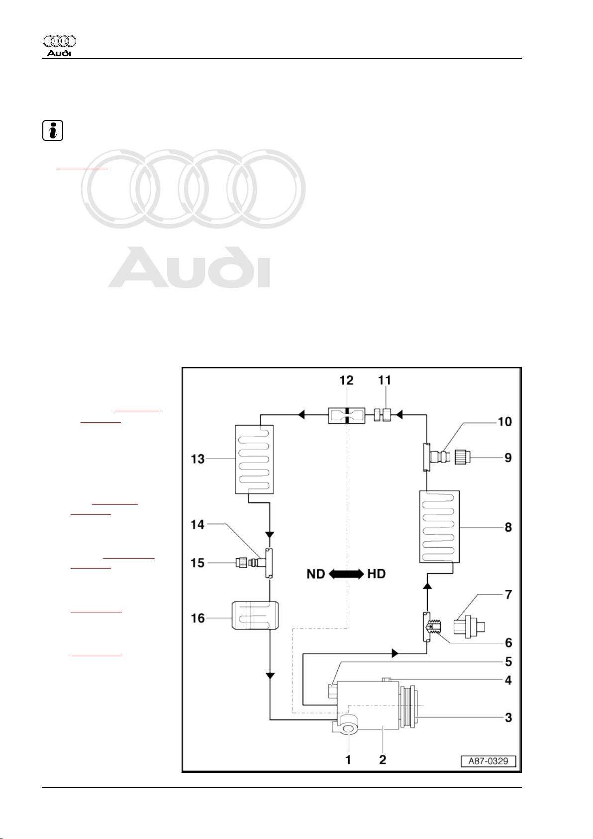
3.1 General view of components
HD = High-pressure end
ND = Low-pressure end
1 - Air conditioner compressor
regulating valve -N280-
❑ Checking actuation and
operation ⇒ page 16
1)
⇒ page 8
2 - Compressor
❑ Detaching compressor
from holder/re-attaching
on vehicles with 6-cyl.
engine, 8-cyl. MPI en‐
gine or 8-cyl. diesel en‐
gine ⇒ page 14 1) and
⇒ page 8
❑ Detaching compressor
from holder/re-attaching
on vehicles with 12-cyl.
engine ⇒ page 149 and
⇒ page 8
❑ Removing and installing
compressor on vehicles
with 8-cyl. FSI engine
⇒ page 141
❑ Removing and installing
compressor on vehicles
with 10-cyl. engine
⇒ page 153
❑ When installing the re‐
frigerant lines and the
corresponding holder,
make sure there is suffi‐
cient distance between
the belt, holder and pul‐
ley.
❑ The type of compressor
differs depending on the
engine (6, 8, 10 or 12cyl. engine, diesel or
8 Rep. gr.87 - Air conditioning system
Protected by copyright. Copying for private or commercial purposes, in part or in whole, is not
permitted unless authorised by AUDI AG. AUDI AG does not guarantee or accept any liability
with respect to the correctness of information in this document. Copyright by AUDI AG.
Audi A8 2003 ➤
Air conditioning - Edition 09.2010
petrol engine) ⇒ Elec‐
tronic parts catalogue
Different refrigerant oil capacities apply to the refrigerant circuit depending on the type of compressor („6 SEU
14“, „7 SEU 16“ or „7 SEU 17“) ⇒ Electronic parts catalogue and ⇒ Air conditioner with refrigerant R134a
3 - Pulley/drive unit for compressor
❑
Replacing compressor pulley 1) ⇒ page 19
❑
Removing and installing poly V-belt 1) ⇒ Engine, mechanics; Rep. gr. 13
❑ Poly V-belt assignment ⇒ Electronic parts catalogue
❑ Replacing compressor drive unit (vehicles with 8-cyl. FSI or 10-cyl. engine) ⇒ page 161
Note
4 - Oil drain plug
5 - Pressure relief valve
6 - Connection with valve
❑ Use an adapter from the adapter set for service connections -T10364- for example for removing and
installing the valve insert with the refrigerant circuit drained.
WARNING
The refrigerant circuit
must always be drained
before removing the
valve insert.
7 - High-pressure sender -G65- 1) ⇒ page 8
❑ Removing and installing ⇒ page 10
❑ Checking signal ⇒ page 10
8 - Condenser
9 - Cap
❑ With seal
❑ Always to be screwed on
10 - Service connection
❑ High-pressure end
❑ For service station for measuring, draining and filling ⇒ Air conditioner with refrigerant R134a
❑ For measurement, drainage and filling; the vehicle is to be taken to a workshop equipped with the nec‐
essary tools where the work can be performed by appropriately qualified personnel ⇒ Air conditioner
with refrigerant R134a
❑ Different versions (with primary sealing valve or Schrader valve) depending on the refrigerant line; dis‐
tinguishing features ⇒ Air conditioner with refrigerant R134a
❑ Use an adapter from the adapter set for service connections -T10364- for example for removing and
installing the service connection or valve insert with the refrigerant circuit drained.
11 - Union in refrigerant line
12 - Restrictor
❑ Fitted in union ⇒ Item 11 (page 9)
13 - Evaporator
14 - Service connection
❑ Low-pressure end
❑ For service station for measurement and drainage ⇒ Air conditioner with refrigerant R134a
❑ For measurement and drainage; the vehicle is to be taken to a workshop equipped with the necessary
tools where the work can be performed by appropriately qualified personnel ⇒ Air conditioner with re‐
frigerant R134a
3. Servicing refrigerant circuit 9
Protected by copyright. Copying for private or commercial purposes, in part or in whole, is not
permitted unless authorised by AUDI AG. AUDI AG does not guarantee or accept any liability
with respect to the correctness of information in this document. Copyright by AUDI AG.
Audi A8 2003 ➤
Air conditioning - Edition 09.2010
❑ Different versions (with primary sealing valve or Schrader valve) depending on the refrigerant line; dis‐
tinguishing features ⇒ Air conditioner with refrigerant R134a
❑ Use an adapter from the adapter set for service connections -T10364- for example for removing and
installing the service connection or valve insert with the refrigerant circuit drained.
WARNING
The refrigerant circuit
must be drained before
removing the service
connections (the con‐
nection has no valve).
15 - Cap
❑ With seal
❑ Always to be screwed on
16 - Reservoir
3.2 Removing and installing air conditioner high-pressure sender -G65-
– Remove the radiator grille ⇒ General body repairs, exterior;
Rep. gr. 50 .
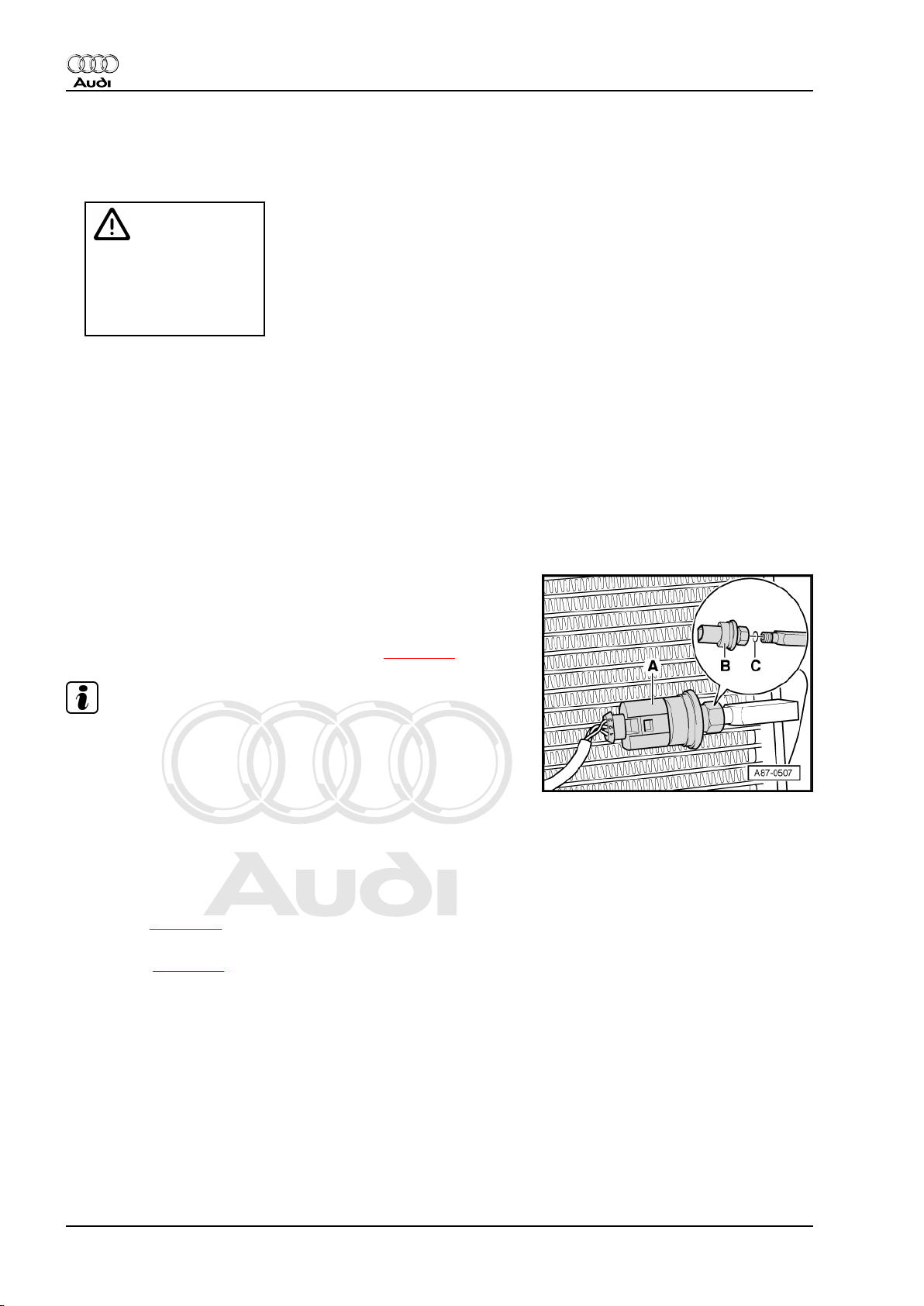
– Unplug the connector -A-.
– Remove the high-pressure sender -G65- -B- (tightening tor‐
que: 5 Nm).
– Replace the O-ring -C- (10.8 mm; 1.8 mm) ⇒ page 13 .
Note
♦
The cooling output cannot be checked with the high-pressure
sender -G65- removed. The front operating and display unit,
Climatronic control unit -J255- does not switch on the com‐
pressor.
♦
There are different versions of the high-pressure sender -G65(different signals). Attention is therefore to be paid to correct
assignment ⇒ Electronic parts catalogue .
♦
The refrigerant circuit is to be left closed, connection with
valve.
♦
Checking operation of high-pressure sender -G65- and signal
supplied ⇒ page 10 .
♦
Moisten the O-ring with a small quantity of refrigerant oil before
installing ⇒ page 13 .
3.3 Checking pressure signal from highpressure sender -G65-
– Remove the radiator grille ⇒ General body repairs, exterior;
Rep. gr. 50 .
10 Rep. gr.87 - Air conditioning system
Protected by copyright. Copying for private or commercial purposes, in part or in whole, is not
permitted unless authorised by AUDI AG. AUDI AG does not guarantee or accept any liability
with respect to the correctness of information in this document. Copyright by AUDI AG.
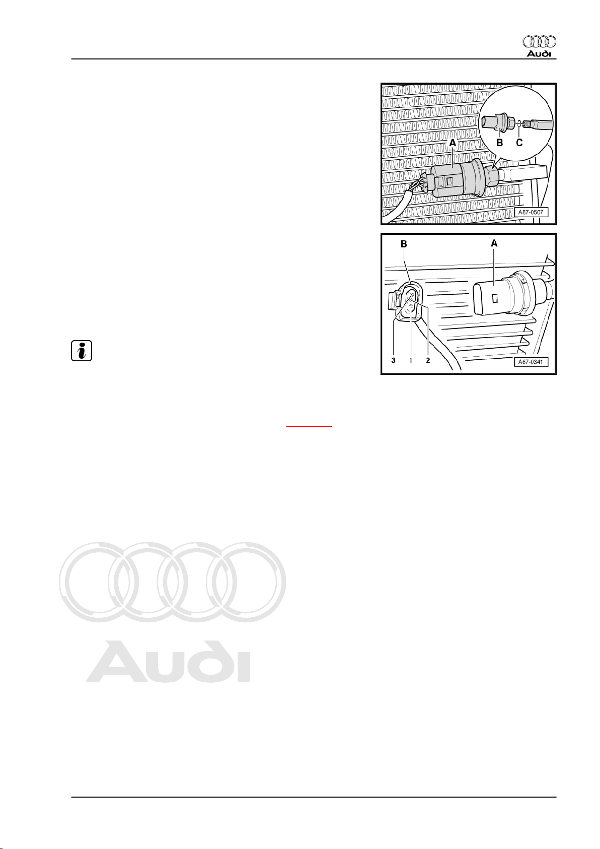
– Unplug the connector -A-.
3.3.1 Pin assignment at high-pressure sender
-G65-
-Contact 1- Earth
-Contact 2- Signal output (square-wave signal to front operating
and display unit, Climatronic control unit -J255- )
-Contact 3- Positive (terminal 75)
Audi A8 2003 ➤
Air conditioning - Edition 09.2010
Note
♦
The compressor is not switched on if the connector -B- is un‐
plugged.
♦
The high-pressure sender -A- is an electronic control unit
which generates a square-wave signal with a ratio which var‐
ies with the pressure in the refrigerant circuit ⇒ page 12 .
♦
3. Servicing refrigerant circuit 11
Protected by copyright. Copying for private or commercial purposes, in part or in whole, is not
permitted unless authorised by AUDI AG. AUDI AG does not guarantee or accept any liability
with respect to the correctness of information in this document. Copyright by AUDI AG.
Audi A8 2003 ➤
Air conditioning - Edition 09.2010
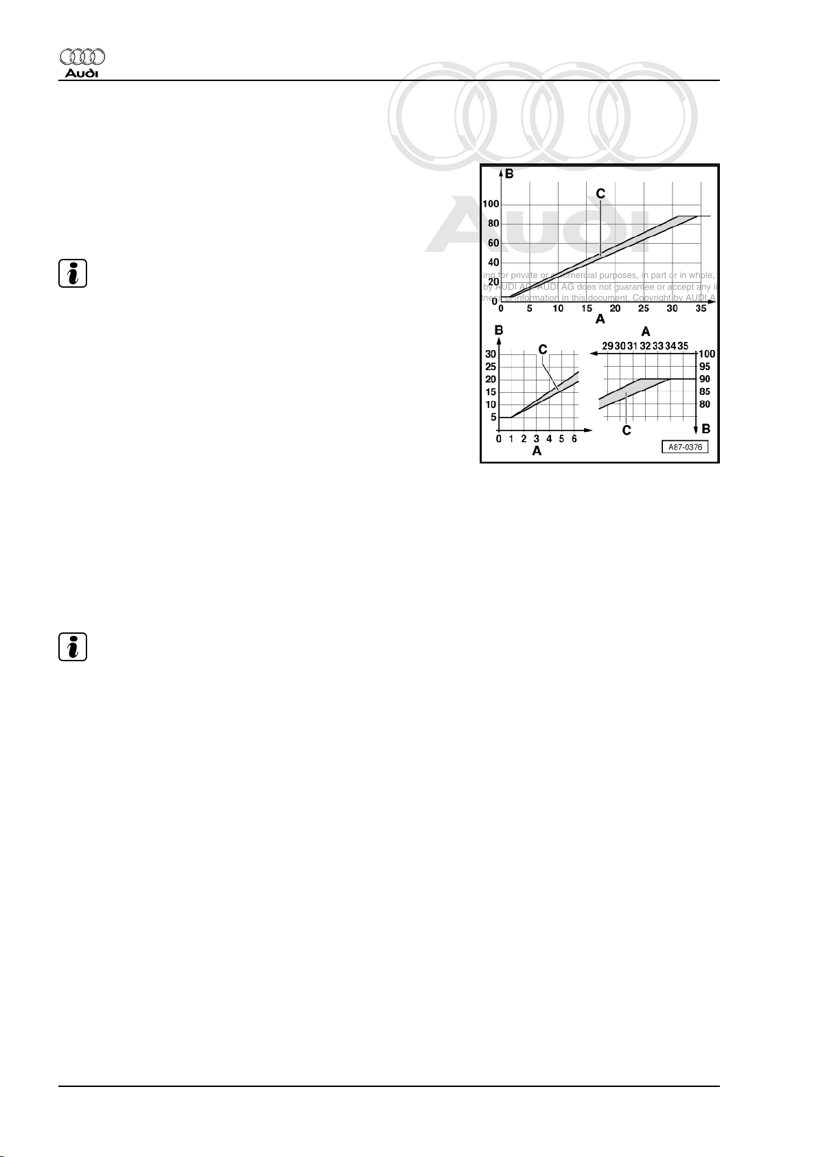
3.3.2 Pressure signal from high-pressure sender -G65-
-A- Pressure on high-pressure end of refrigerant circuit in bar
(absolute)
-B- Ratio of square-wave signal
-C- Characteristic curve
Note
♦
As soon as there are no compressor shut-off criteria, the front
operating and display unit, Climatronic control unit -J255switches on the compressor (by actuating the air conditioner
compressor regulating valve -N280- ):
♦
The signal generated by the high-pressure sender -G65- is
also used for engine control. The front operating and display
unit, Climatronic control unit -J255- transmits the information
via the convenience data bus system to the engine control unit
(the torque required for driving the compressor is governed by
the pressure in the refrigerant circuit). Depending on the ver‐
sion of the engine control unit, the signal is displayed as a ratio
in the measured value block ⇒ "Guided fault-finding" function
of vehicle diagnostic, testing and information system
VAS 5051 (for engine control unit)
♦ The pressure in the refrigerant circuit is OK (the front operating
and display unit, Climatronic control unit -J255- does not de‐
tect any compressor shut-off criteria)
– If the ratio is greater than 12 % (corresponding to approx. 1.8
bar absolute) and less than 87.5% (corresponding to approx.
32 bar absolute)
Note
♦
If the signal ratio is less than 12 % or greater than 87.5%, the
compressor is not switched on (the air conditioner compressor
regulating valve -N280- is not actuated).
♦
The signal ratio and the pressure calculated by the front op‐
erating and display unit, Climatronic control unit -J255- are
indicated in the measured value block ⇒ "Guided fault-finding"
function of vehicle diagnostic, testing and information system
VAS 5051.
♦
At absolute pressure, 0 bar corresponds to an absolute vac‐
uum. Normal ambient pressure thus corresponds to roughly 1
bar absolute. On the scales of most pressure gauges, 0 bar
corresponds to an absolute pressure of one bar (can be seen
from -1 mark below 0).
♦ The front operating and display unit, Climatronic control unit -
J255- transmits the request for radiator fan actuation via the
convenience data bus system to the engine control unit, which
then switches on the radiator fan by way of the fan control unit:
– Irrespective of the pressure in the refrigerant circuit as soon
as the compressor is switched on
12 Rep. gr.87 - Air conditioning system
Protected by copyright. Copying for private or commercial purposes, in part or in whole, is not
permitted unless authorised by AUDI AG. AUDI AG does not guarantee or accept any liability
with respect to the correctness of information in this document. Copyright by AUDI AG.
– Depending on the pressure calculated in the refrigerant circuit,
the front operating and display unit, Climatronic control unit J255- transmits the request for increased radiator fan speed
to the engine control unit via the convenience data bus system
with the compressor actuated. The fan speed determined by
the front operating and display unit, Climatronic control unit J255- is displayed in the measured value block ⇒ "Guided
fault-finding" function of vehicle diagnostic, testing and infor‐
mation system VAS 5051.
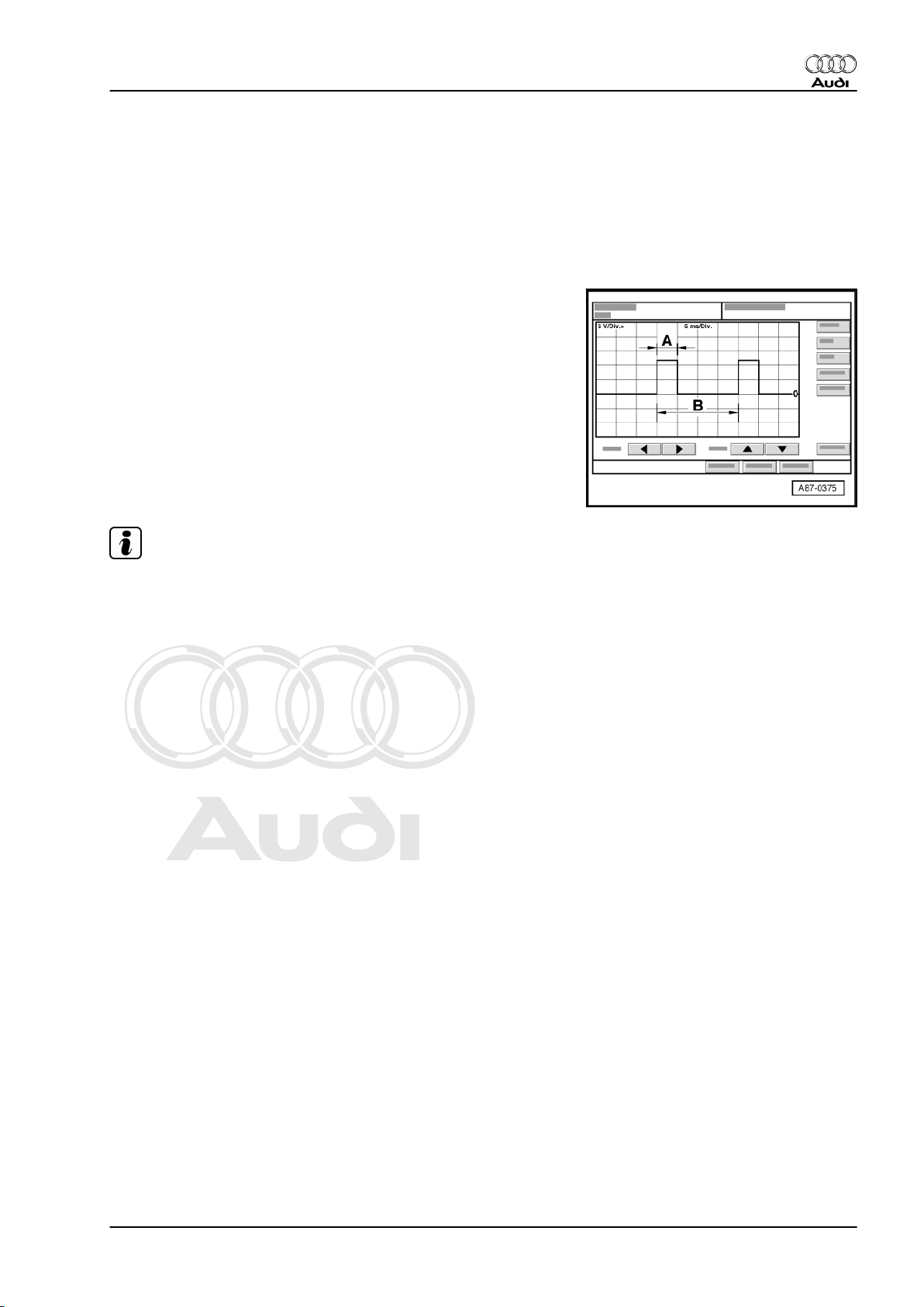
This pattern will appear on the oscilloscope screen (e.g. on the
vehicle diagnostic, testing and information system -VAS 5051 A- )
if the following conditions are satisfied.
– Ignition on (positive at contact „3“ and earth at contact „1“ at
high-pressure sender -G65- )
– Setting on oscilloscope: 5 V/div. DC (5 V per unit DC voltage)
5 ms/div. (5 milliseconds per unit)
– Test lead (signal wire) connected to contact „2“ at high-pres‐
sure sender -G65-
– Test lead (screen) connected to contact „1“ (earth at high-
pressure sender -G65- )
Audi A8 2003 ➤
Air conditioning - Edition 09.2010
Note
♦
Use can be made for connection of the high-pressure sender
-G65- of test leads from the Adapter set -V.A.G 1594 C- for
example.
♦
The illustration shows the signal transmitted at a refrigerant
circuit pressure of approx. 7 bar absolute, corresponding to a
signal ratio of approx. 25% (level occurring with compressor
not running, ambient temperature of 30 °C and refrigerant cir‐
cuit charged).
♦
The pulse width -A- is governed by the pressure in the refrig‐
erant circuit (area -A- becomes broader as pressure increa‐
ses).
♦
The signal distance -B- is always 20 milliseconds (correspond‐
ing to a frequency of 50 hertz).
♦
The signal ratio is derived from the ratio of pulse width -A- to
signal distance -B-.
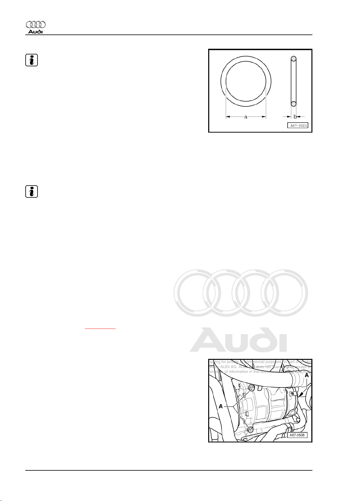
3.4 O-rings for refrigerant circuit
♦ Always replace, only to be used once.
♦ Moisten with refrigerant oil before fitting.
♦ Ensure correct positioning on pipe/in groove.
♦ Ensure cleanliness when working.
3. Servicing refrigerant circuit 13
Protected by copyright. Copying for private or commercial purposes, in part or in whole, is not
permitted unless authorised by AUDI AG. AUDI AG does not guarantee or accept any liability
with respect to the correctness of information in this document. Copyright by AUDI AG.
Audi A8 2003 ➤
Air conditioning - Edition 09.2010
Note
♦
Use is only to be made of O-rings which are resistant to re‐
frigerant R134a and the corresponding refrigerant oil. Such Orings are colour coded to prevent mix-ups (currently „red“,
„lilac“ or „violet“): ⇒ Electronic parts catalogue
♦
Dimensions -a- and -b- differ depending on the fitting location
of the O-ring: ⇒ Electronic parts catalogue
♦
In addition to the coloured O-rings, use is also made at the
factory of black O-rings for certain connections.
3.5 Detaching compressor from holder/at‐
taching on vehicles with 6-cyl. engine, 8cyl. MPI engine or 8-cyl. diesel engine
Compressor drive via poly V-belt
Note
♦
The compressor can be detached from the holder and re-at‐
tached without opening up the refrigerant lines.
♦
Do not drain the refrigerant circuit, do not detach the refriger‐
ant hoses and lines at the compressor.
♦
After detaching, use a piece of wire for example to attach the
compressor to the longitudinal member. Never leave hanging
from the refrigerant lines.
♦
Before removing, mark the direction of the poly V-belt with
chalk or a felt-tip pen. Running a used belt in the opposite di‐
rection could destroy it.
♦
Different compressors are fitted depending on the engine and
country version (6, 8, 10 or 12-cyl. engine, petrol or diesel en‐
gine). ⇒ Electronic parts catalogue
♦
On vehicles with 8-cyl. diesel engine, the compressor is fitted
at the top between the two cylinder heads.
♦
Detaching compressor from holder/re-attaching on vehicles
with 12-cyl. engine ⇒ page 149
3.5.1 Detaching compressor from holder/reattaching
14 Rep. gr.87 - Air conditioning system
Protected by copyright. Copying for private or commercial purposes, in part or in whole, is not
permitted unless authorised by AUDI AG. AUDI AG does not guarantee or accept any liability
with respect to the correctness of information in this document. Copyright by AUDI AG.
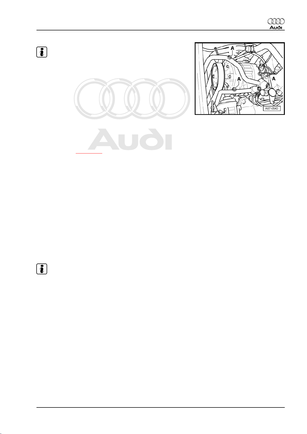
Note
♦
Do not unfasten the refrigerant lines and corresponding
clamps.
♦
This illustration shows the compressor for the 8-cyl. MPI en‐
gine. The layout for the other engine versions only differs
slightly from this illustration (e.g. different refrigerant lines). ⇒
Engine, mechanics; Rep. gr. 13
♦
Depending on the vehicle model, it may be necessary to press
aside or detach certain hoses in the area of the compressor.
♦
This illustration shows the compressor for the 8-cyl. diesel en‐
gine.
♦
Depending on the type of bolts -A- and the routing of the re‐
frigerant line, it may be necessary to detach the refrigerant
lines from the compressor (drain the refrigerant circuit) to
slacken off and remove the bolts -A- on vehicles with an 8-cyl.
diesel engine ⇒ page 138 .
– Remove the top engine cover (vehicles with 8-cyl. diesel en‐
gine only): ⇒ Engine, mechanics; Rep. gr. 13
– Remove the noise insulation ⇒ General body repairs, exterior;
Rep. gr. 50 .
– Move the lock carrier to the service position ⇒ General body
repairs, exterior; Rep. gr. 50 .
– Remove the oil filter if necessary. Protect the sealing surfaces
to prevent damage (certain vehicles with 6-cyl. petrol engine
only). ⇒ Engine, mechanics; Rep. gr. 17
– Slacken off the poly V-belt (poly V-belt for air conditioner com‐
pressor on vehicles with 6-cyl. diesel engine) and detach the
belt. ⇒ Engine, mechanics; Rep. gr. 13
– Mark the connector to the air conditioner compressor regulat‐
ing valve -N280- to prevent possible interchange with the
connector to the electric engine mounting.
Audi A8 2003 ➤
Air conditioning - Edition 09.2010
Note
If the connectors to the air conditioner compressor regulating
valve -N280- and the electric engine mounting are interchanged,
no entry is made in the fault memory, but the evaporator could ice
up as the compressor is constantly actuated.
– Unplug the air conditioner compressor regulating valve -N280-
at the connector.
3. Servicing refrigerant circuit 15
Protected by copyright. Copying for private or commercial purposes, in part or in whole, is not
permitted unless authorised by AUDI AG. AUDI AG does not guarantee or accept any liability
with respect to the correctness of information in this document. Copyright by AUDI AG.
Audi A8 2003 ➤
Air conditioning - Edition 09.2010
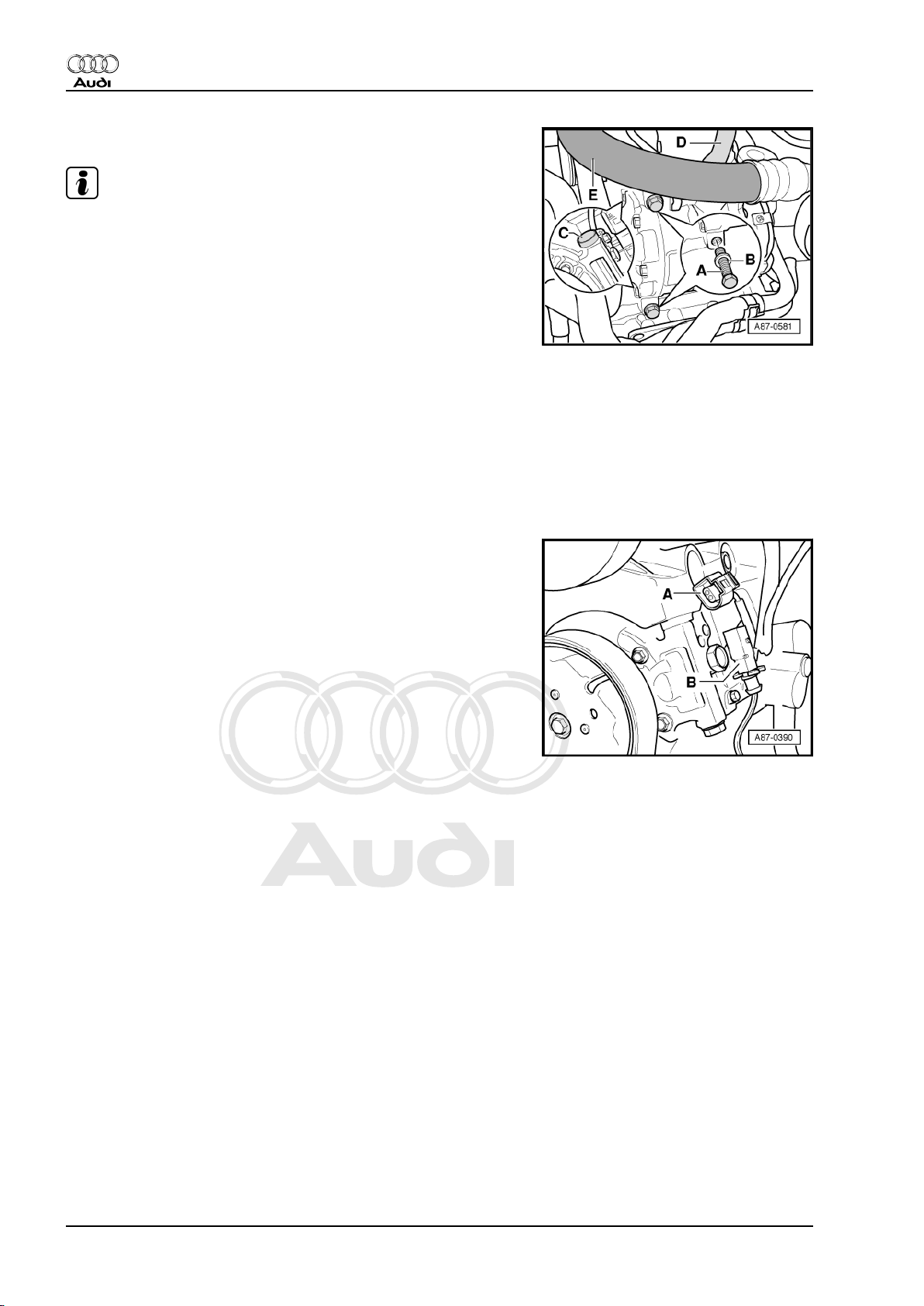
– Screw out the bolts -A- (25 Nm).
Note
♦
Fit one washer -B- at each of the bolts -A-.
♦
Before attaching the compressor, check the position of both
bushes -C- in the holder or compressor.
♦
After attaching the compressor, check the routing of the re‐
frigerant lines -D- and -E-. They must be inserted in the holders
provided (if fitted, depends on engine).
♦
After attaching the compressor, also check the refrigerant
lines and the corresponding holders for adequate clearance
with respect to the other components, ensuring a sufficient
distance between the belt, holder and pulley.
3.6 Checking activation signal for air condi‐
tioner compressor regulating valve N280-
– Switch off ignition.
– Unplug the connector at the air conditioner compressor.
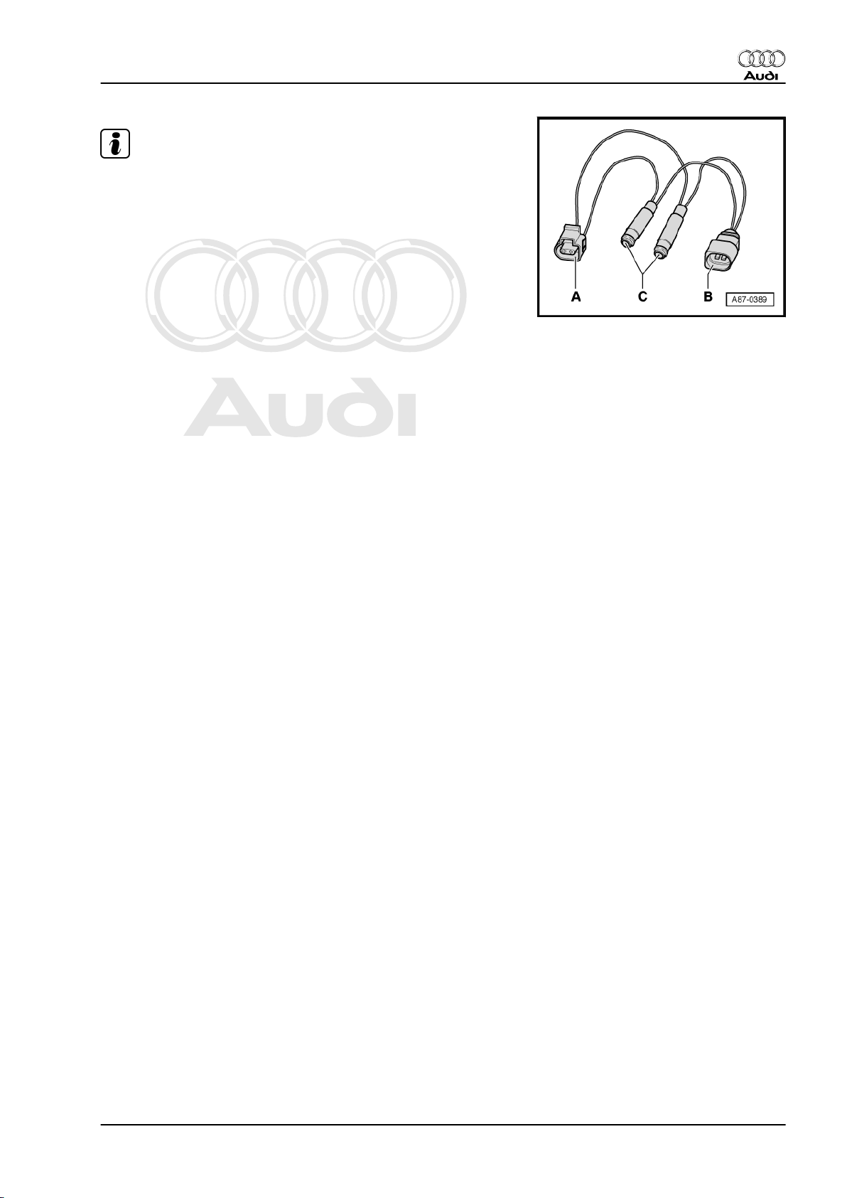
– Use an adapter cable from the adapter set -V.A.G 1594 C- to
re-establish the connection between connector -A- and con‐
nector -B- at the regulating valve.
16 Rep. gr.87 - Air conditioning system
Protected by copyright. Copying for private or commercial purposes, in part or in whole, is not
permitted unless authorised by AUDI AG. AUDI AG does not guarantee or accept any liability
with respect to the correctness of information in this document. Copyright by AUDI AG.
Note
♦
Actuation of the air conditioner compressor regulating valve N280- and the current measured by the front operating and
display unit, Climatronic control unit -J255- which flows via the
air conditioner compressor regulating valve -N280- are dis‐
played in the measured value block of the front operating and
display unit, Climatronic control unit -J255- ⇒ "Guided faultfinding" function of vehicle diagnostic, testing and information
system VAS 5051.
♦
An adapter cable can also be produced for this test. This re‐
quires, for example, one connector -A- and -B- each (with part
number 1J0 973 702 and 1J0 973 802 and the corresponding
plug contacts), two commercially available sockets for banana
plugs -C- and two wires with a cross section of 0.5 mm2.
– Connect the probe -VAS 5051/8- to the adapter leads.
– Test lead (signal wire) to contact -2-
– Test lead (screen, earth) to contact -1-
– On the vehicle diagnostic, testing and information system -
VAS 5051 A- , set Measurement mode: DSO (digital storage
oscilloscope).
Audi A8 2003 ➤
Air conditioning - Edition 09.2010
– Settings 5V/div DC, 0.5 ms/div (5 V DC and 0.5 milliseconds
per unit)
– Start the engine.
– On the front operating and display unit, Climatronic control unit
-J255- , set the temperature to „Lo“.
– On the front operating and display unit, Climatronic control unit
-J255- , press the buttons „Auto“ and „Off/On“ to activate and
deactivate the air conditioner compressor regulating valve N280- .
The display on the oscilloscope screen will be as follows depend‐
ing on the setting on the front operating and display unit, Clima‐
tronic control unit -J255- :
– In „OFF“ mode: No square-wave signal (regulating valve is not
actuated)
3. Servicing refrigerant circuit 17
Protected by copyright. Copying for private or commercial purposes, in part or in whole, is not
permitted unless authorised by AUDI AG. AUDI AG does not guarantee or accept any liability
with respect to the correctness of information in this document. Copyright by AUDI AG.
Audi A8 2003 ➤
Air conditioning - Edition 09.2010
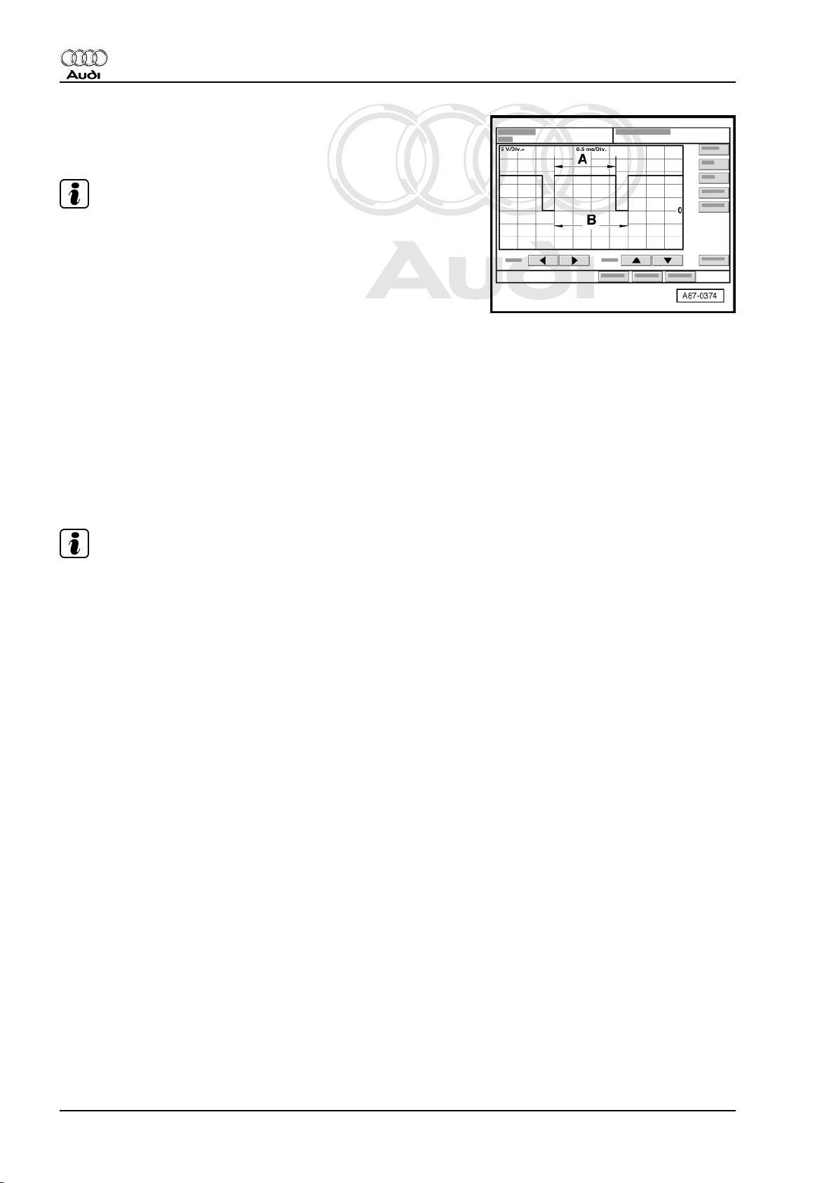
– In „Auto“ mode and „Lo“ temperature setting: Square-wave
signal with pulse width -A- between 75% and 100% (regulating
valve is actuated)
Note
♦
The illustration shows a signal with a signal ratio of approx.
80%.
♦
The pulse width -A- is governed by the required cooling output,
the electrical system voltage etc. (over the width of area -A-,
the current is controlled via the air conditioner compressor
regulating valve -N280- by the front operating and display unit,
Climatronic control unit -J255- ).
♦
The signal distance -B- is always 2 milliseconds (correspond‐
ing to a frequency of 500 hertz).
♦
The signal ratio is derived from the ratio of pulse width -A- to
signal distance -B-.
– The setting on the front operating and display unit, Climatronic
control unit -J255- and the measured ambient influences gov‐
ern the pulse width of the square-wave signal (signal ratio
between 100% and greater than 30%, the regulating valve is
actuated such that the compressor output required to obtain
the specified temperatures is achieved).
Note
♦
In „Auto“ mode with „Lo“ temperature setting, the air condi‐
tioner compressor regulating valve -N280- is actuated such
that the maximum permissible current of approx. 0.65 A flows
via the air conditioner compressor regulating valve -N280(maximum compressor output).
♦
In control mode, the actuation time is governed by the required
cooling output and the vehicle electrical system voltage, for
example. It is however always of sufficient duration to achieve
a mean current of 0.3 A.
18 Rep. gr.87 - Air conditioning system
Protected by copyright. Copying for private or commercial purposes, in part or in whole, is not
permitted unless authorised by AUDI AG. AUDI AG does not guarantee or accept any liability
with respect to the correctness of information in this document. Copyright by AUDI AG.
4 Replacing compressor pulley
4.1 Replacing pulley
(Version „1“ )
Note
♦
Various pulley designs are fitted depending on the type of
compressor and the engine version ⇒ Electronic parts cata‐
logue .
♦
Detaching pulley from compressor/re-attaching ⇒ page 20
♦
Pulley version „1“ is attached for example to the type „7 SEU
16“ compressor.
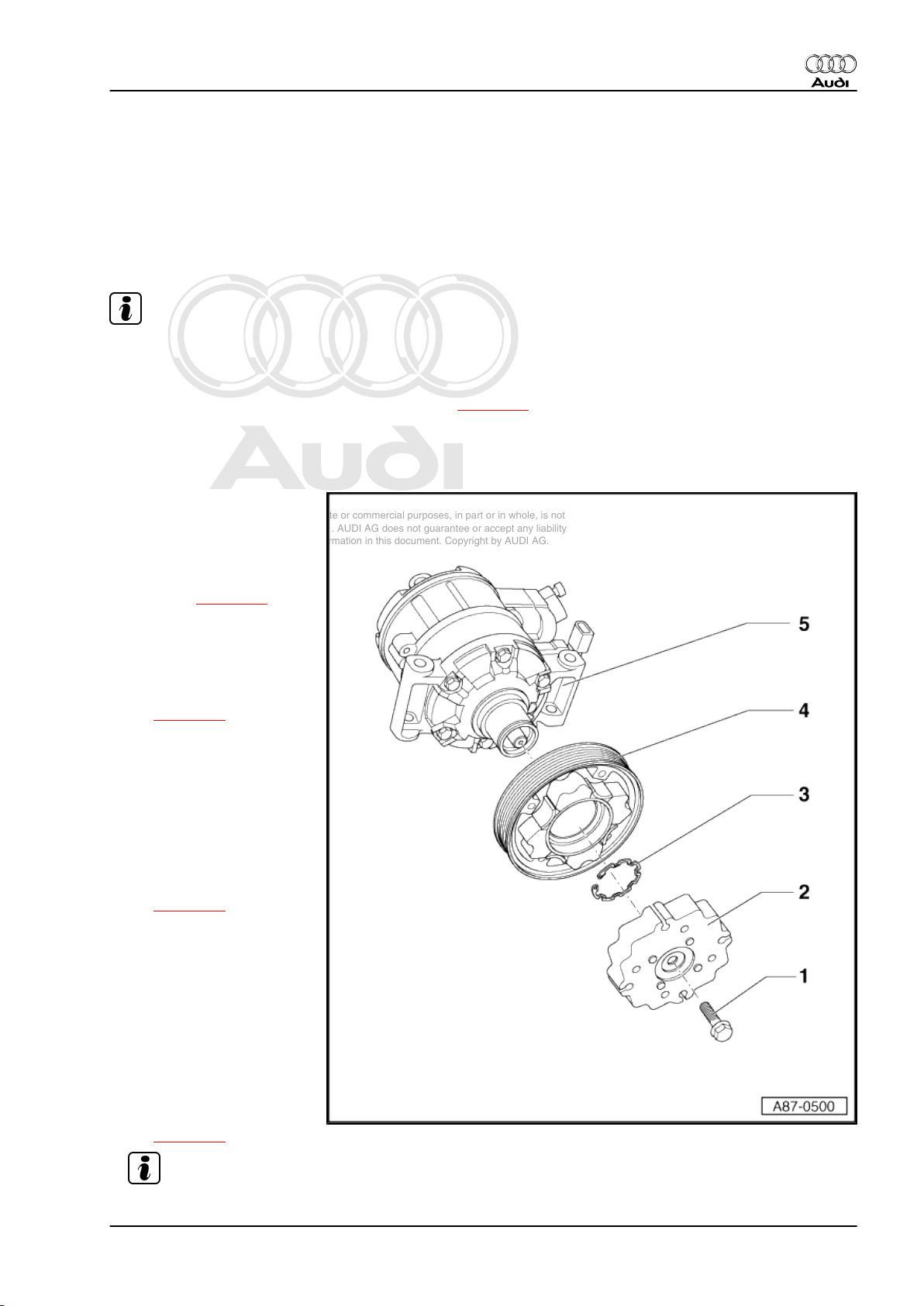
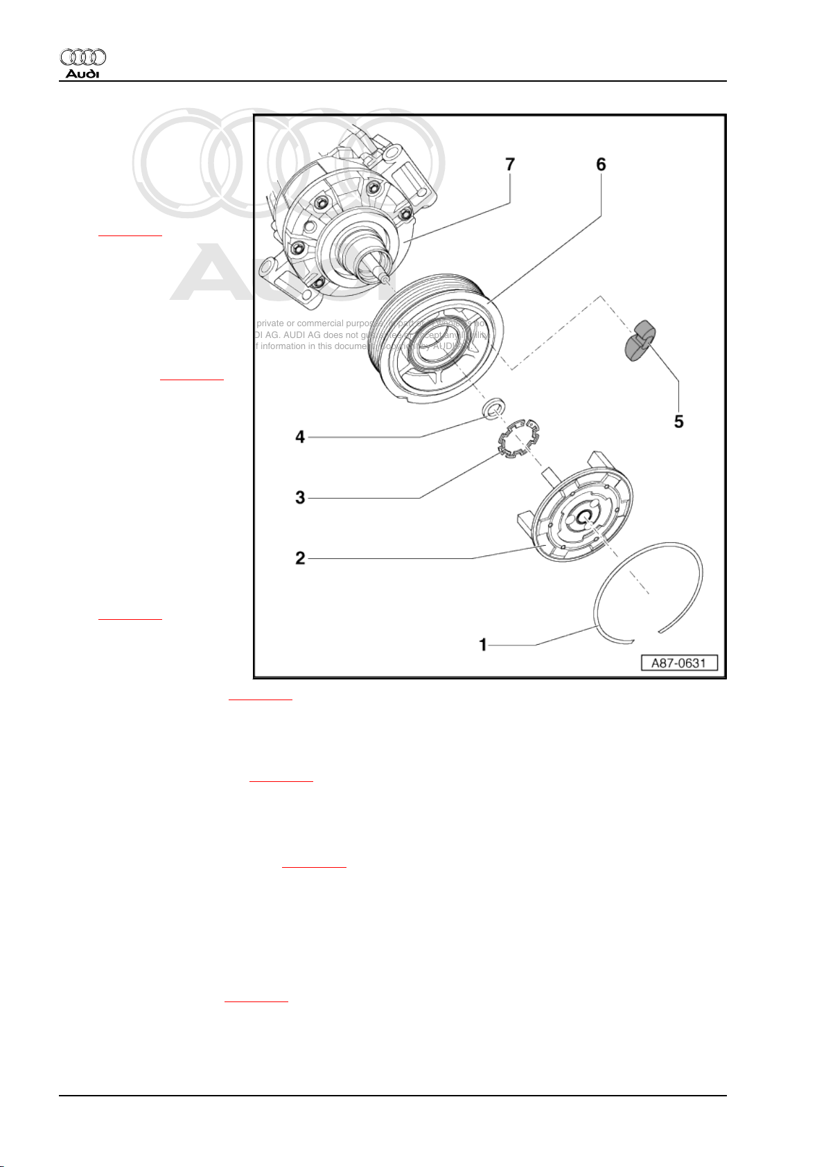
1 - Bolt
❑ Replace
❑ Tightening torque 20
Nm
❑ Slackening off and tight‐
ening ⇒ page 20
2 - Drive plate
❑ Different versions ⇒
Electronic parts cata‐
logue
❑ Detaching/attaching
⇒ page 20
❑ Tripped in the event of
excessive torque (e.g.
compressor stiff)
Audi A8 2003 ➤
Air conditioning - Edition 09.2010
3 - Circlip
❑ Replace
❑ Ensure correct position‐
ing (flat side facing com‐
pressor)
❑ Removing and installing
⇒ page 20
4 - Pulley
❑ Rubber element of pul‐
ley is tripped in the event
of excessive torque
(e.g. stiff compressor)
and pulley just turns
without driving com‐
pressor
❑ Different versions ⇒
Electronic parts cata‐
logue
❑ Detaching/attaching
⇒ page 20
Note
4. Replacing compressor pulley 19
Protected by copyright. Copying for private or commercial purposes, in part or in whole, is not
permitted unless authorised by AUDI AG. AUDI AG does not guarantee or accept any liability
with respect to the correctness of information in this document. Copyright by AUDI AG.
Audi A8 2003 ➤
Air conditioning - Edition 09.2010
5 - Compressor
❑ Different models are fitted depending on engine and country version of vehicle ⇒ Electronic parts cata‐
logue
❑ Clean the flange of the compressor before fitting the pulley.
4.2 Detaching pulley from compressor/reattaching
(Version „1“ )
Note
♦
If the pulley overload safeguard has been tripped, check the
freedom of movement of the compressor before replacing the
pulley. Replace the entire compressor if stiff.
♦
The pulley overload protection function is described e.g. in
⇒ Self-study programme No. 240 ; Audi A2 Technology .
♦
Depending on the engine version, detachment of the pulley
may involve separating the compressor from the engine
⇒ page 14 .
♦
On most vehicles (except certain vehicles with 8-cyl. diesel
engine), the compressor can be detached from the holder and
re-attached without opening up the refrigerant lines.
♦
Prior to removal, mark the direction of the poly V-belt with chalk
or a felt-tip pen. Running a used belt in the opposite direction
could destroy it.
♦
Different compressors are fitted depending on engine and
country version (6, 8 or 12-cyl. engine, petrol or diesel engine)
⇒ Electronic parts catalogue
– Remove the top engine cover (vehicles with 8-cyl. diesel en‐
gine only): ⇒ Engine, mechanics; Rep. gr. 13
– Remove the noise insulation ⇒ General body repairs, exterior;
Rep. gr. 50 .
– Move the lock carrier to the service position ⇒ General body
repairs, exterior; Rep. gr. 50 .
– Slacken off and detach the poly V-belt. ⇒ Engine, mechanics;
Rep. gr. 13
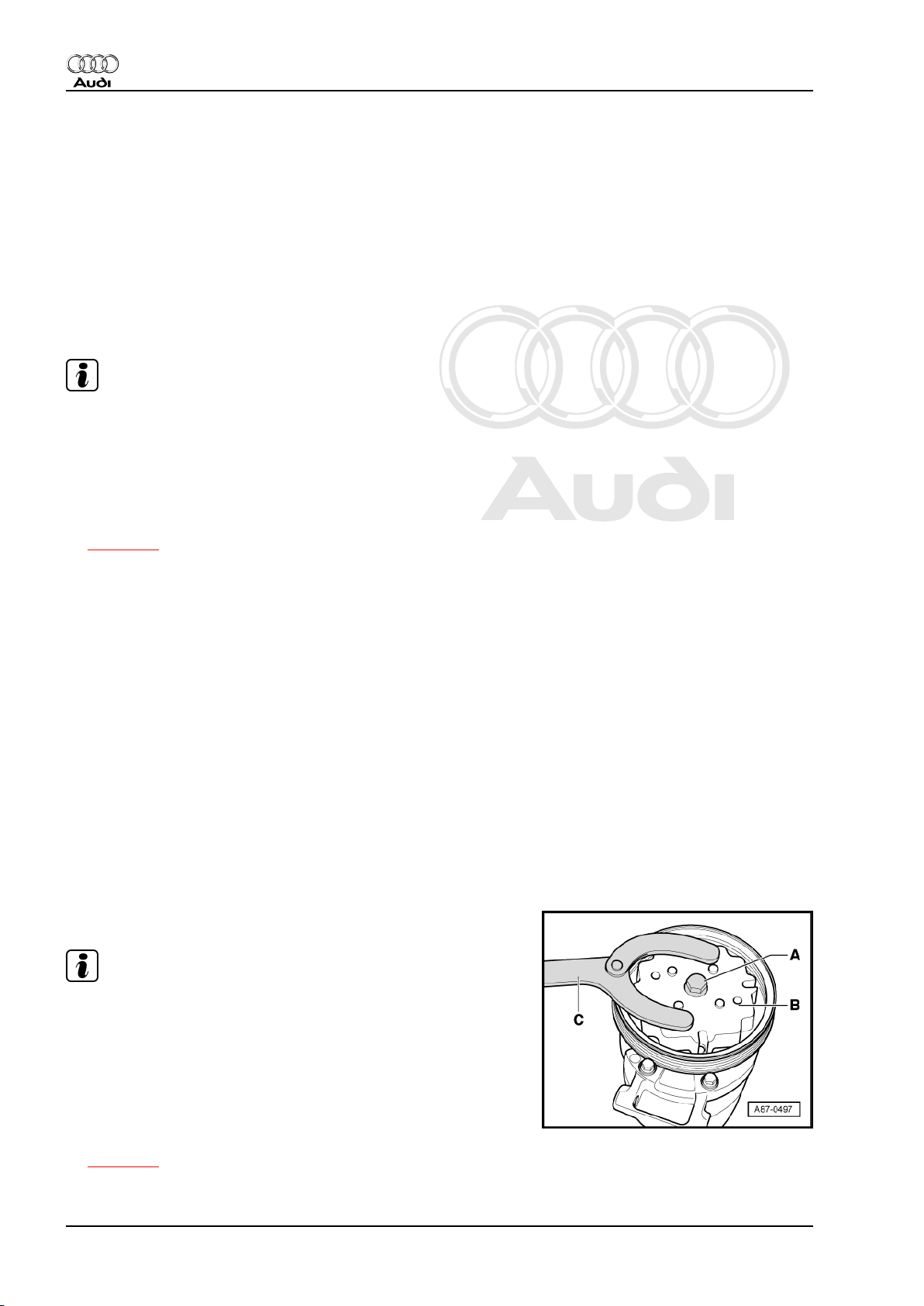
– Screw out the bolt -A- (tightening torque 20 Nm).
Note
♦
When slackening off and tightening the bolt -A-, provide sup‐
port with a commercially available pin wrench -C- (pin diame‐
ter 5.0 mm) at the drive plate -B-.
♦
The bolt -A- is to be replaced (on account of locking fluid).
♦
Clean the thread in the shaft of the compressor before insert‐
ing the new bolt.
♦
Should it not be possible to detach the pulley with the com‐
pressor in position, separate the compressor from the engine
⇒ page 14 .
20 Rep. gr.87 - Air conditioning system
Protected by copyright. Copying for private or commercial purposes, in part or in whole, is not
permitted unless authorised by AUDI AG. AUDI AG does not guarantee or accept any liability
with respect to the correctness of information in this document. Copyright by AUDI AG.
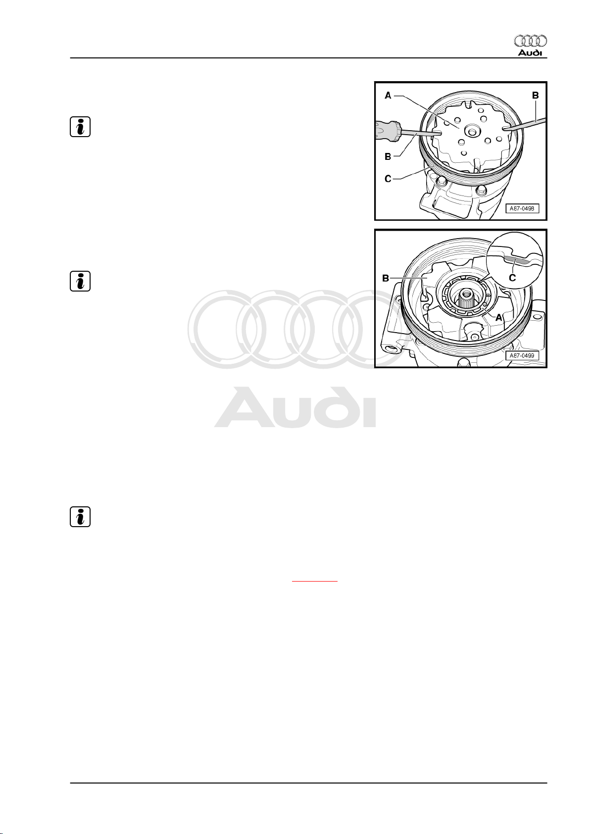
– Carefully and evenly prise off the drive plate -A- using 2 screw‐
drivers -B-.
Note
♦
When prising off the drive plate -A-, take care not to damage
the collar of the pulley -C-.
♦
There are different types of pulley -C- and drive plate -A-. At‐
tention must therefore be paid to precise assignment. ⇒
Electronic parts catalogue
– Remove the circlip -A-.
– Detach the pulley -B-.
Note
♦
Replace the circlip -A-.
♦
On fitting the circlip -A-, take care not to bend it open more
than necessary.
♦
Ensure correct insertion of the circlip -A-. The bevelled side
-C- faces away from the compressor (flat side faces compres‐
sor).
♦
Make sure the circlip is properly positioned in the groove at the
compressor flange.
♦
Clean the compressor flange before fitting the pulley. The pul‐
ley must be easy to fit (without having to exert force).
Audi A8 2003 ➤
Air conditioning - Edition 09.2010
4.3 Replacing pulley
(Version „2“ )
Note
♦
Various pulley designs are fitted depending on the type of
compressor and the engine version ⇒ Electronic parts cata‐
logue .
♦
Detaching pulley from compressor/re-attaching ⇒ page 23
♦
Pulley version „2“ is attached for example to type „6 SEU 14“
and „7 SEU 17“ compressors.
4. Replacing compressor pulley 21
Protected by copyright. Copying for private or commercial purposes, in part or in whole, is not
permitted unless authorised by AUDI AG. AUDI AG does not guarantee or accept any liability
with respect to the correctness of information in this document. Copyright by AUDI AG.
Audi A8 2003 ➤
Air conditioning - Edition 09.2010
1 - Circlip
❑ Remove carefully using
a small screwdriver or
pointed-nose pliers
(paying particular atten‐
tion to the pulley)
❑ Detaching/attaching
⇒ page 23
❑ As of Model Year 2006,
circlips are being gradu‐
ally introduced which
are provided with a
vulcanised rubber disc
to replace the plastic
disc which may be bon‐
ded on at present (not
applicable to all com‐
pressors) ⇒ page 23
2 - Drive plate
❑ Screwed to compressor
drive shaft
❑ Different versions ⇒
Electronic parts cata‐
logue
❑ With overload safe‐
guard, tripped in the
event of excessive tor‐
que (e.g. stiff compres‐
sor) and pulley just freewheels without driving
compressor
❑ Detaching/attaching
⇒ page 23
❑ Tightening torque 35
Nm
❑ A plastic disc may have
been affixed depending
on production period ⇒ page 23 .
3 - Circlip
❑ Replace
❑ Ensure correct positioning (flat side facing compressor)
❑ Removing and installing ⇒ page 23
4 - Spacer
❑ Dimensions: 17.5 x 10 x 3 mm
5 - Rubber element
❑ 6x, ensure correct installation ⇒ page 23
❑ Decouples pulley from compressor drive shaft, damps vibration and noise
❑ On installation, moisten the rubber elements slightly with tyre assembly paste or soap solution for ex‐
ample to provide lubrication.
6 - Pulley
❑ The pulley is made of plastic, is sensitive to impact and should therefore be treated with extreme care.
❑ Different versions ⇒ Electronic parts catalogue
❑ Detaching/attaching ⇒ page 23
7 - Compressor
❑ Different models are fitted depending on engine and country version of vehicle ⇒ Electronic parts cata‐
logue
22 Rep. gr.87 - Air conditioning system
Protected by copyright. Copying for private or commercial purposes, in part or in whole, is not
permitted unless authorised by AUDI AG. AUDI AG does not guarantee or accept any liability
with respect to the correctness of information in this document. Copyright by AUDI AG.
❑ Clean the flange of the compressor before fitting the pulley.
4.4 Detaching pulley from compressor/reattaching
(Version „2“ )
Audi A8 2003 ➤
Air conditioning - Edition 09.2010
Note
♦
Heed the notes on removal of the version „1“ pulley, as these
also apply to version „2“ ⇒ page 20 .
♦
Perform preparatory work as described for detaching the ver‐
sion „1“ pulley ⇒ page 20 .
♦
The pulley is made of plastic, is sensitive to impact and should
therefore be treated with extreme care.
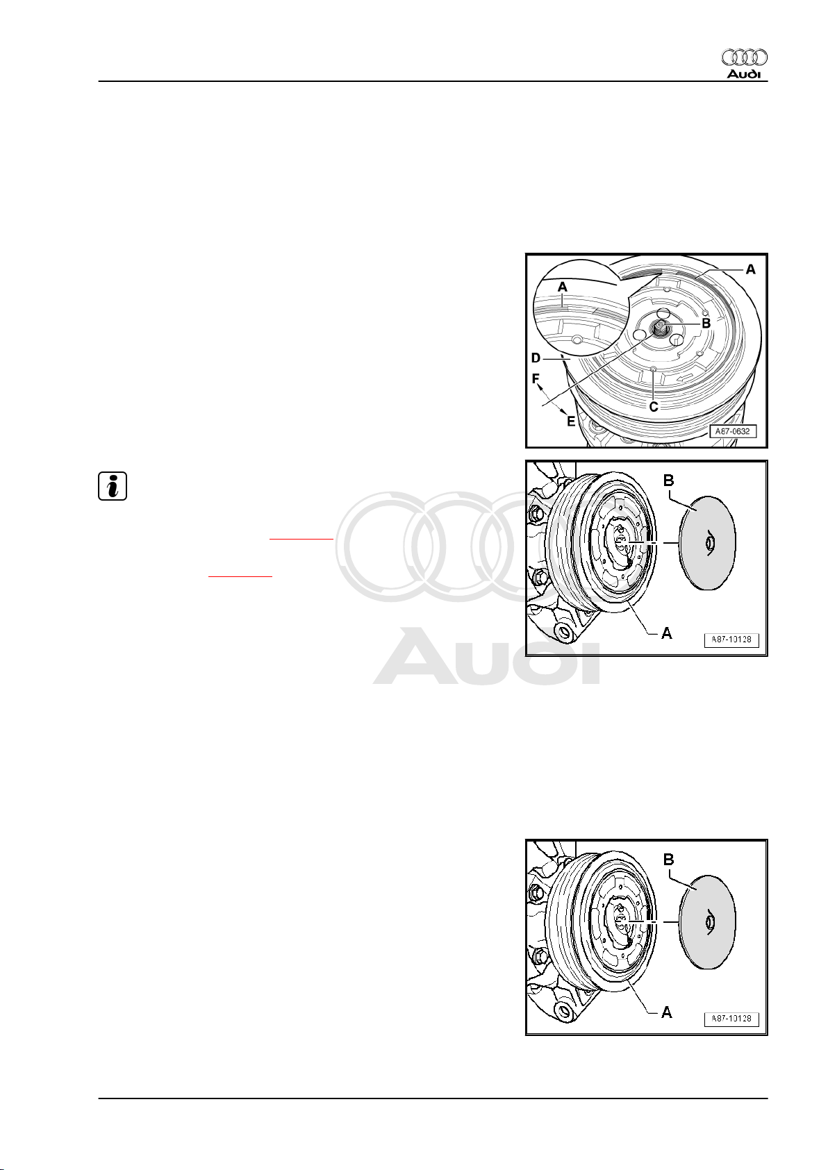
♦
If the overload safeguard of the drive plate -C- has been trip‐
ped, remove the circlip -A- and then prise the drive plate off
the pulley -D-.
♦
For noise optimisation, a plastic disc -B- may have been af‐
fixed to the drive plate of the pulley -A- or a circlip with a
vulcanised rubber disc may have been fitted ⇒ Electronic
parts catalogue . This plastic or rubber disc -B- reduces the
rattling (castanet-like) noise which can occur at the pulley par‐
ticularly in the case of vehicles with diesel engine in air con‐
ditioner „Econ mode“ (A/C mode off) (in air conditioner full load
operation the noise is scarcely audible).
Detaching pulley
– Remove the plastic disc -B- from the pulley -A- (if fitted).
4. Replacing compressor pulley 23
Protected by copyright. Copying for private or commercial purposes, in part or in whole, is not
permitted unless authorised by AUDI AG. AUDI AG does not guarantee or accept any liability
with respect to the correctness of information in this document. Copyright by AUDI AG.
Audi A8 2003 ➤
Air conditioning - Edition 09.2010
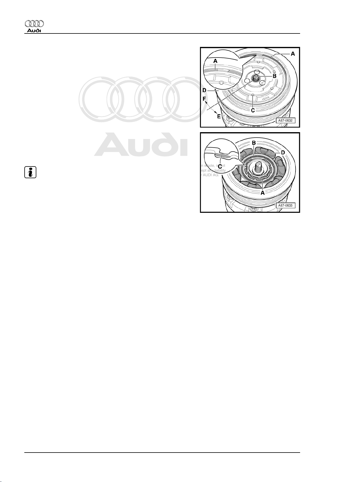
– Use a small screwdriver or pointed-nose pliers, for example,
to carefully remove the circlip -A- (possibly with vulcanised
rubber disc), taking particular care not to damage the pulley.
– Hold the compressor drive shaft -B- in position for example
with a socket attachment or a socket wrench -T10001/10- from
the wrench set (depending on version) and turn the drive plate
-C- with the pulley -D- in the direction of arrow -E- (tightening
torque 35 Nm).
– Remove the circlip -A-.
– Detach the pulley -B-.
Attaching pulley
Note
♦
Replace the circlip -A-.
♦
Clean the compressor flange before attaching the pulley.
♦
On fitting the circlip -A-, take care not to bend it open more
than necessary.
– Fit the pulley -B-.
– Ensure correct insertion of the circlip -A-. The bevelled side
-C- faces away from the compressor (flat side faces compres‐
sor).
– Insert the rubber elements -D- in the pulley -B- as shown.
– For fitting the drive plate, moisten the rubber elements -D-
slightly with tyre assembly paste or soap solution for example
to provide lubrication.
– Insert the drive plate -C- in the rubber elements -D- (refer to
illustration above) until it makes contact with the shaft of the
compressor -B-.
– Screw the drive plate -C- onto the compressor shaft -B- by
turning it in direction of arrow -F-.
– Tighten the drive plate -C- to 35 Nm by turning it with a com‐
mercially available strap wrench (with fabric strap) in the di‐
rection of arrow -F-. Provide support for the compressor shaft
-A- by applying a counterhold -B- (e.g. socket attachment or
socket wrench -T10001/10- from wrench set) to the compres‐
sor shaft -A-.
– Fit the circlip -A-.
24 Rep. gr.87 - Air conditioning system
 Loading...