

Audi A8 292, A8 Service
Service
292
Home study program 292
For internal company use only
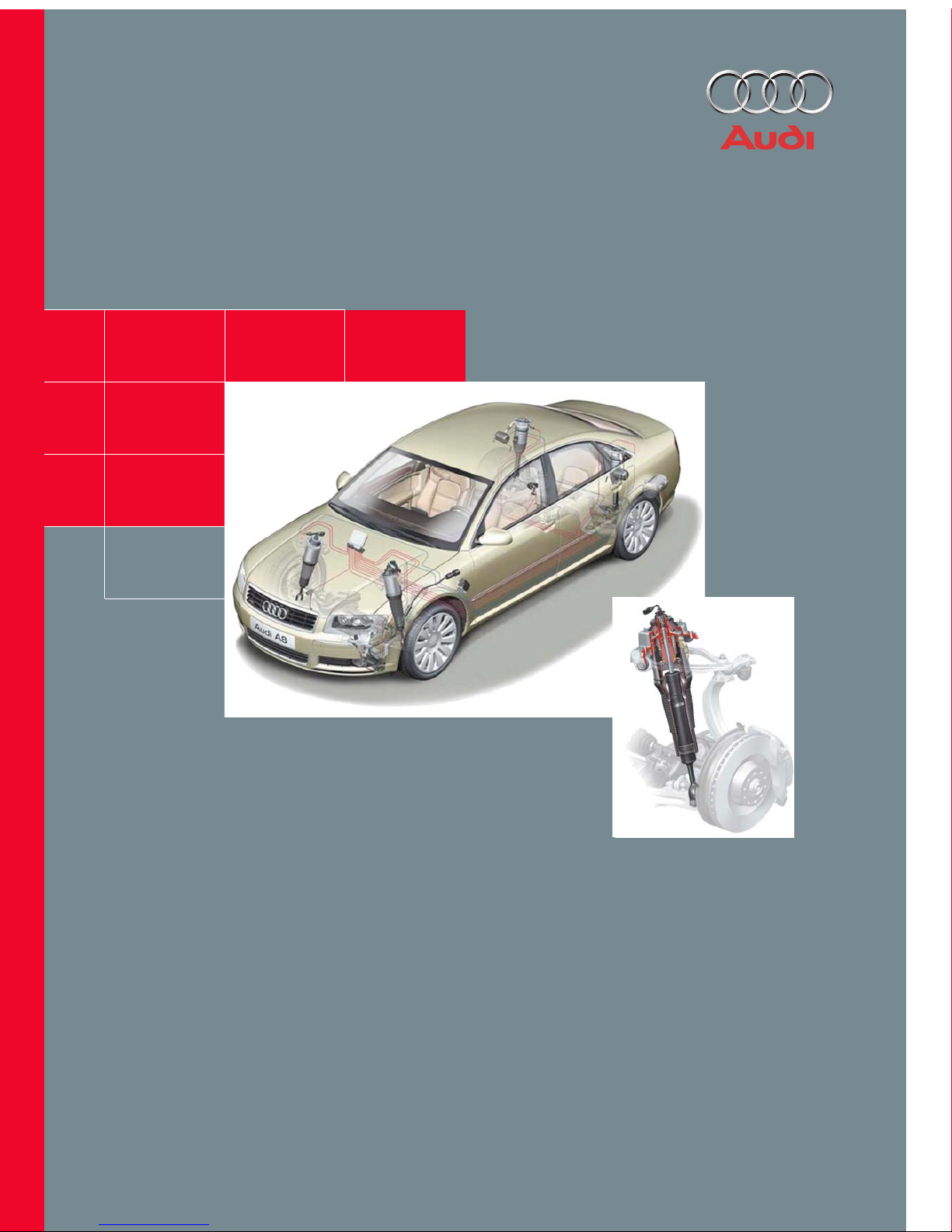
adaptive air suspension
in the Audi A8
The development of the running gear is subject to conflicting objectives. For now, besides
"classic" aims such as function, driving safety, strength and durability, requirements such as
weight reduction, driving comfort and acoustics are increasingly gaining in importance.
At first glance, many requirements appear to be in mutual opposition. A car designed to be
very comfortable will lose out in terms of driving safety when driven at the limit.
On the other hand, a car with very sporty tuning will achieve considerably higher cornering
speeds, and will reach its limit much later. However, this sporty tuning necessarily entails limitations when it comes to comfort.
In the Audi A8 MY 2003, a newly developed, fully bearing air suspension system is used.
In conjunction with the CDC status-dependent electronic damping control, this ensures that
the main - and partly conflicting - requirements are satisfied in an optimum manner within the
limits of the laws of physics.

3
Contents
Page
Caution!
Note!
New!
The home study program informs you about designs and
functions.
The home study program is not a Repair Manual!
All values stated herein are purely intended to facilitate your
understanding of the program, and are based on the software
version valid at the time the SSP was compiled.
For service and repair work, it is important that you please use
the current technical literature.
Introduction
Basics . . . . . . . . . . . . . . . . . . . . . . . . . . . . . . . . . . . . . . . . . . . . . . . . . . . . . . . . . . . . . . 4
New technology. . . . . . . . . . . . . . . . . . . . . . . . . . . . . . . . . . . . . . . . . . . . . . . . . . . . . . 4
Operation and display
Vehicle levels . . . . . . . . . . . . . . . . . . . . . . . . . . . . . . . . . . . . . . . . . . . . . . . . . . . . . . . . 6
Operation and display system . . . . . . . . . . . . . . . . . . . . . . . . . . . . . . . . . . . . . . . . . . 9
System components
Vehicle overview . . . . . . . . . . . . . . . . . . . . . . . . . . . . . . . . . . . . . . . . . . . . . . . . . . . . 10
Control unit J197 . . . . . . . . . . . . . . . . . . . . . . . . . . . . . . . . . . . . . . . . . . . . . . . . . . . . 12
Suspension/shock absorber strut . . . . . . . . . . . . . . . . . . . . . . . . . . . . . . . . . . . . . . 13
Shock absorber . . . . . . . . . . . . . . . . . . . . . . . . . . . . . . . . . . . . . . . . . . . . . . . . . . . . . 14
Air supply unit . . . . . . . . . . . . . . . . . . . . . . . . . . . . . . . . . . . . . . . . . . . . . . . . . . . . . . 15
Solenoid valve block . . . . . . . . . . . . . . . . . . . . . . . . . . . . . . . . . . . . . . . . . . . . . . . . . 16
Accumulator. . . . . . . . . . . . . . . . . . . . . . . . . . . . . . . . . . . . . . . . . . . . . . . . . . . . . . . . 16
Pneumatic diagram . . . . . . . . . . . . . . . . . . . . . . . . . . . . . . . . . . . . . . . . . . . . . . . . . . 18
Pressure build-up. . . . . . . . . . . . . . . . . . . . . . . . . . . . . . . . . . . . . . . . . . . . . . . . . . . . 19
Pressure reduction . . . . . . . . . . . . . . . . . . . . . . . . . . . . . . . . . . . . . . . . . . . . . . . . . . 19
Senders (sensors) . . . . . . . . . . . . . . . . . . . . . . . . . . . . . . . . . . . . . . . . . . . . . . . . . . . 20
System functions
Control concept for standard running gear . . . . . . . . . . . . . . . . . . . . . . . . . . . . . . 26
Control concept for sporty running gear . . . . . . . . . . . . . . . . . . . . . . . . . . . . . . . . 28
Control concept for special operating conditions . . . . . . . . . . . . . . . . . . . . . . . . . 29
Interfaces
System overview of components with bus link (CAN, MOST) . . . . . . . . . . . . . . . 34
System overview of components without bus link . . . . . . . . . . . . . . . . . . . . . . . . 35
CAN information exchange . . . . . . . . . . . . . . . . . . . . . . . . . . . . . . . . . . . . . . . . . . . 36
Function diagram . . . . . . . . . . . . . . . . . . . . . . . . . . . . . . . . . . . . . . . . . . . . . . . . . . . 38
Other interfaces. . . . . . . . . . . . . . . . . . . . . . . . . . . . . . . . . . . . . . . . . . . . . . . . . . . . . 40
Service
Control unit code. . . . . . . . . . . . . . . . . . . . . . . . . . . . . . . . . . . . . . . . . . . . . . . . . . . . 42
System initialisation . . . . . . . . . . . . . . . . . . . . . . . . . . . . . . . . . . . . . . . . . . . . . . . . . 42
Final control diagnosis . . . . . . . . . . . . . . . . . . . . . . . . . . . . . . . . . . . . . . . . . . . . . . . 43
Measured value blocks . . . . . . . . . . . . . . . . . . . . . . . . . . . . . . . . . . . . . . . . . . . . . . . 43
4
Introduction
Basics
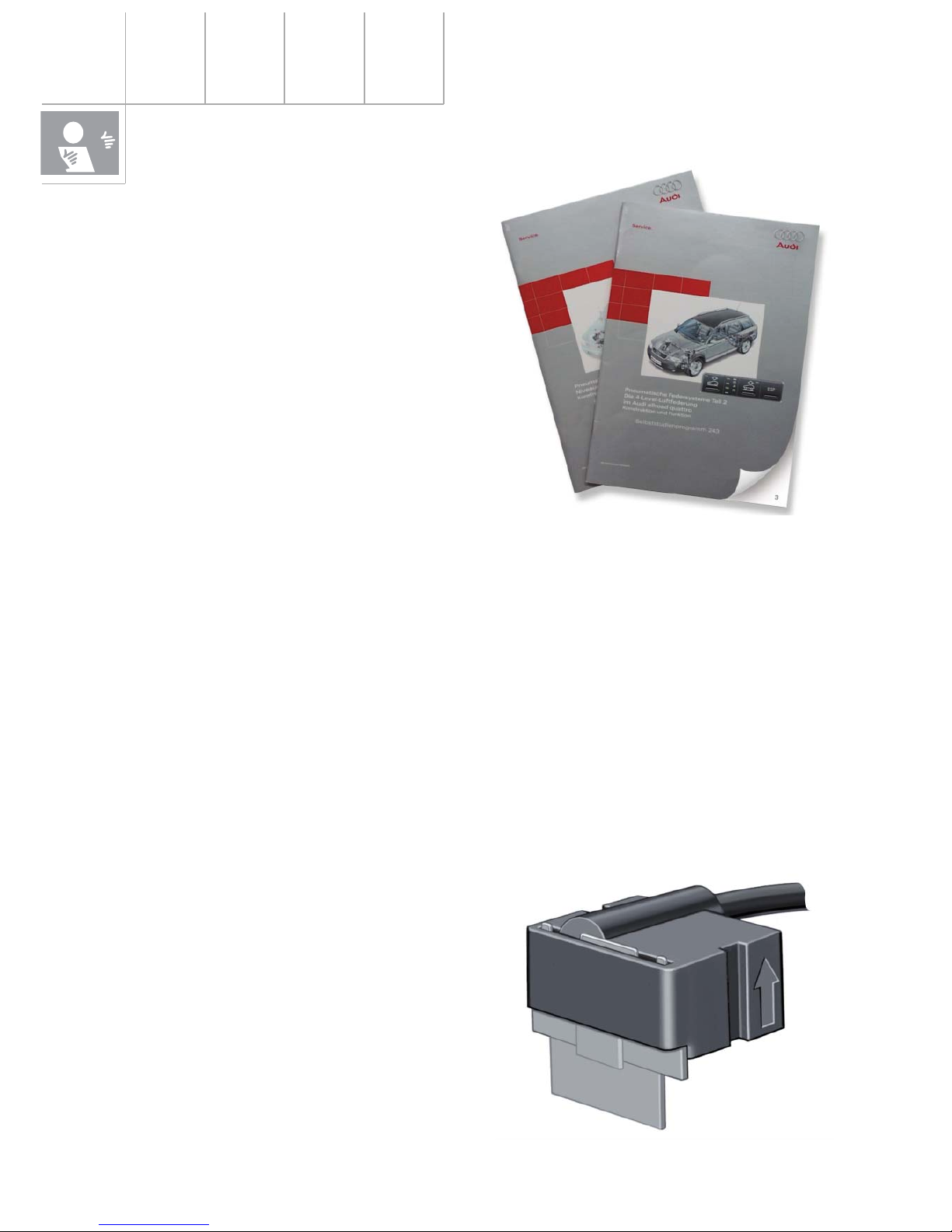
The basics for understanding air suspension
systems are contained in home study programs 242 and 243 and are of course also
valid for the system to be introduced in the
A8 from model year 2003.
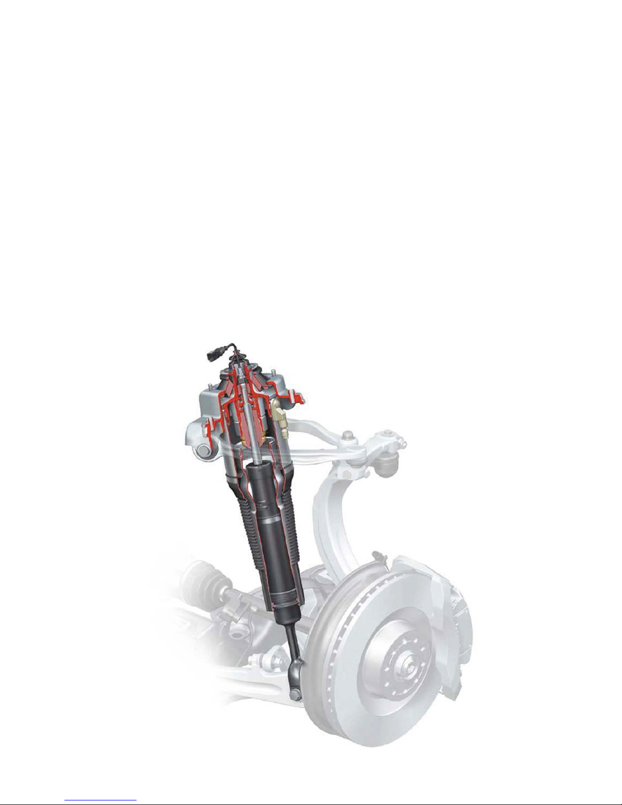
New technology
The new A8 heralds a new system in terms of
technical content and range of functions. It
differs from the known system of the allroad
quattro in the following features:
CDC instead of PDC damping control:
The control takes account of the current driving status. The wheel movements (unsprung
masses) and body movements (sprung
masses) are recorded.
Within the choice of four programs (modes),
different damping characteristics are
implemented. In this process, each shock
absorber can be controlled independently.
292_001
Therefore, in each mode which is selected
(comfortable or sporty), the maximum degree
of comfort and driving safety is ensured (see
description "Shock absorber" in the "System
components" section).
The term "mode" can therefore be understood
to be the well-balanced combination of the
adaptive air suspension program and the
damping map.
292_025
Enhanced sensor system:
Three acceleration sensors are employed to
record the body movement.
(See description "Body acceleration sender"
in the "System components" section.)
5
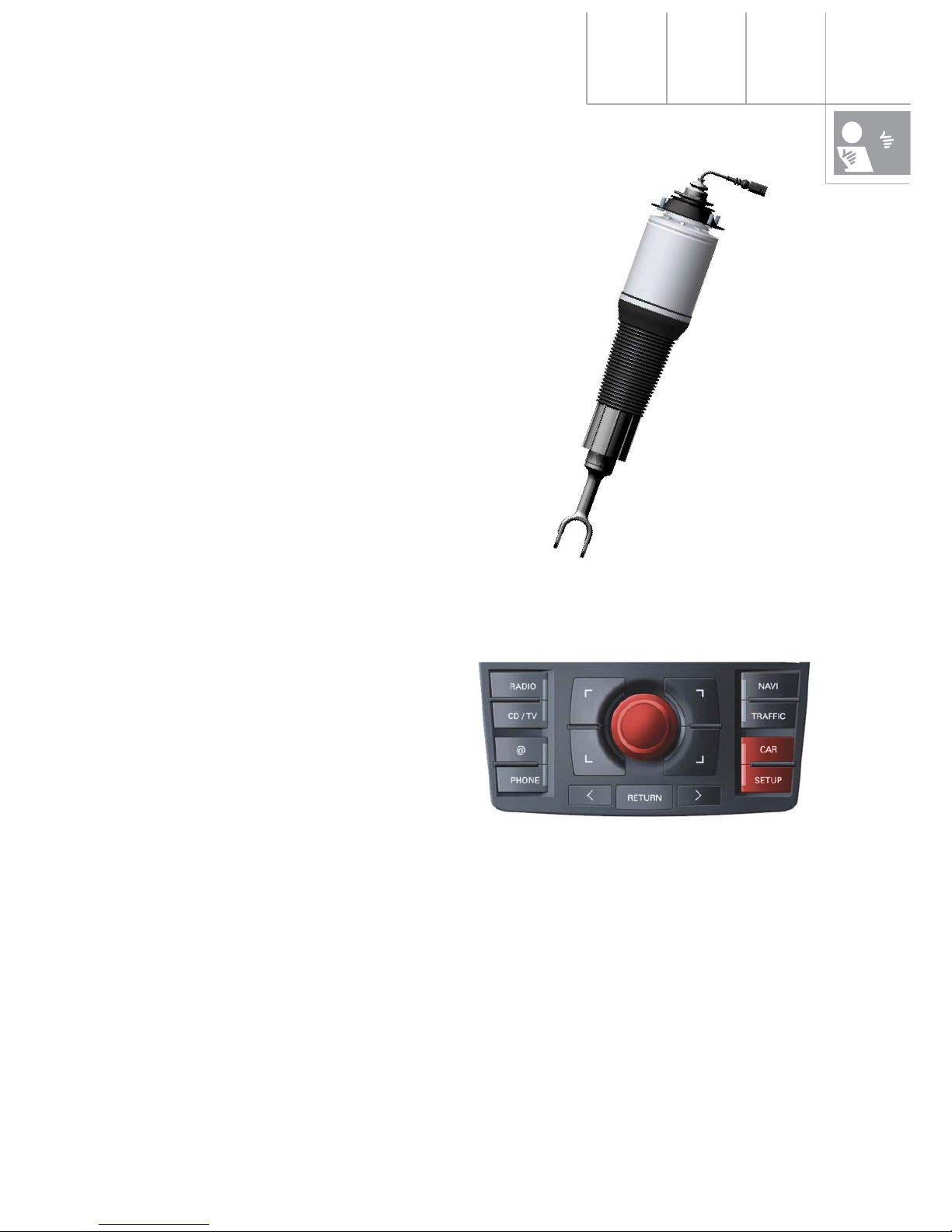
Operation:
Integration in the MMI means that operation
is user-friendly, logical and easy to learn.
(See description in the "Operation and display" section.)
292_003
292_002
Residual pressure retaining valves:
Each suspension strut features residual pressure retaining valves directly at the air connection. This ensures that a minimum pressure of approx. 3.5 bar is maintained in the pneumatic
springs. This practically eliminates the risk of damage during storage and assembly to the
greatest possible extent.
Encased pneumatic springs:
The air bellows are encased in an aluminium
cylinder. The result is a considerable improvement in the response characteristic.
(See description "Pneumatic springs" in the
"System components" section.)
6
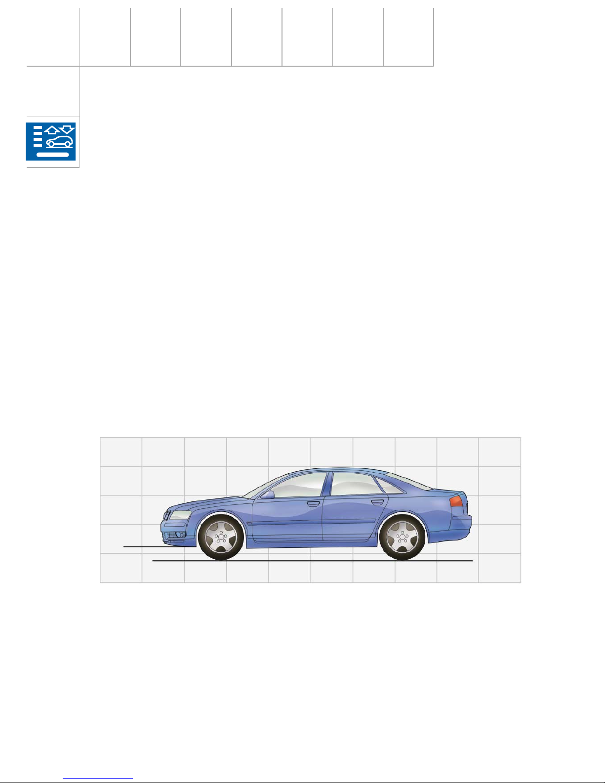
Operation and display
Vehicle levels
The A8 comes either with a standard running gear (adaptive air suspension) or a sporty running gear (adaptive air suspension-sport).
Standard running gear:
The following programs can be selected either manually or automatically:
"automatic" mode:
Basic vehicle level, comfort-oriented suspension with appropriately adapted damper map. The
vehicle is lowered by 25 mm after 30 seconds at speeds of 75 mph (120 km/h) or more ("motorway lowering"). This lowered position improves aerodynamics and reduces fuel consumption.
"comfort" mode:
Vehicle height as in "automatic" mode, less damping at lower speeds than in "automatic"
mode, resulting in even greater driving comfort than in "automatic" mode.
There is no automatic motorway lowering.
292_005
"automatic" and "comfort" mode: Basic level
Basic level
of standard
running
gear
7
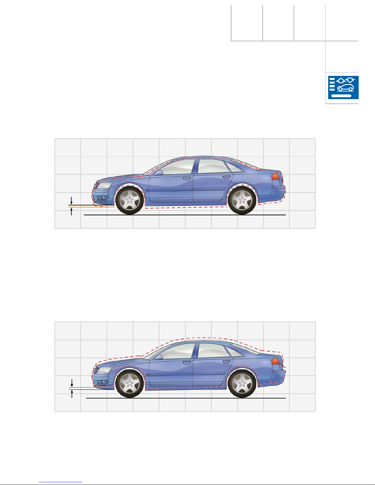
292_006
"lift" mode: + 25 mm
+ 25 mm
"lift" mode:
Vehicle level is 25 mm higher than in "automatic" mode, comfort-oriented suspension like
"automatic" mode.
292_004
"dynamic" mode: - 20 mm
- 20 mm
"dynamic" mode:
Vehicle level is 20 mm lower than in "automatic" mode. The damper map is automatically set to
sporty. After 30 seconds at speeds of 75 mph (120 km/h) or more, the car is lowered by another
5 mm ("motorway lowering").
8
Operation and display
"lift" mode:
Level 25 mm higher than "automatic" mode of sporty running gear, sporty suspension.
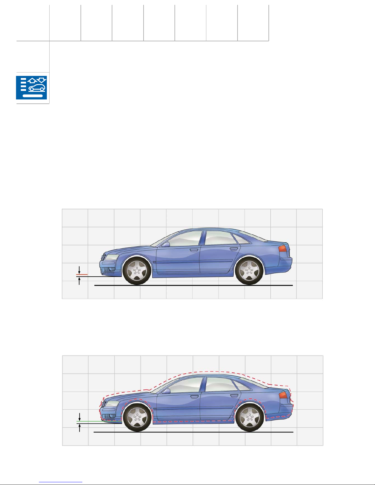
Sporty running gear:
"automatic" mode:
Basic vehicle level corresponds to "dynamic" mode in the standard running gear, sporty
suspension with appropriately adapted damper map (more comfortable than "dynamic"
mode). The vehicle is lowered by another 5 mm after 30 seconds at speeds of 75 mph
(120 km/h) or more ("motorway lowering").
292_049
"dynamic", "automatic" and "comfort" mode: Basic level for sporty running gear
Basic level of sporty
running gear (-20 mm)
Basic level
of standard
running
gear
292_006
"lift" mode: + 25 mm
+ 25 mm
"dynamic" mode:
Level as for "automatic" mode of sporty running gear, hard, sporty suspension with appropriately adapted damper map. The vehicle is lowered by 5 mm after 30 seconds at speeds of 75
mph (120 km/h) or more ("motorway lowering").
"comfort" mode:
Level as for "automatic" mode of sporty running gear, less damping at lower speeds than in
"automatic" mode. There is no automatic motorway lowering.
9
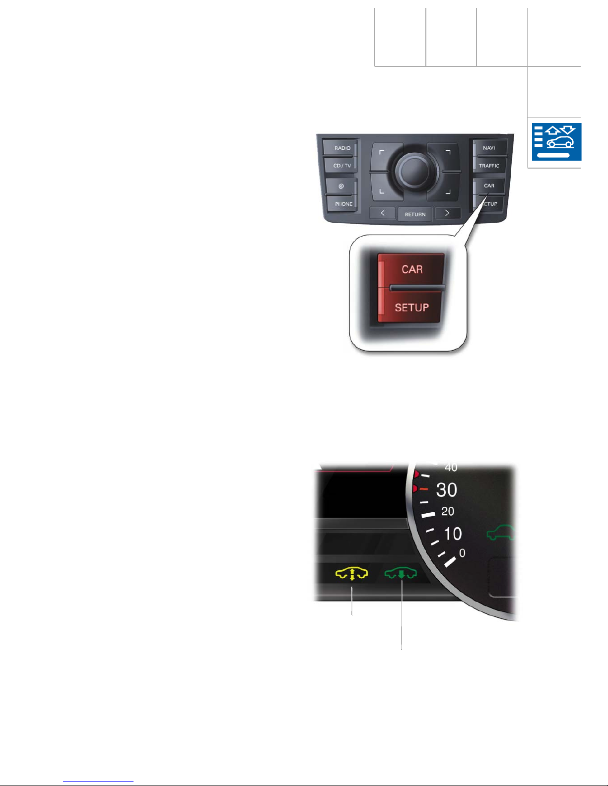
Operation and display system
The process of switching from one mode to
another and the display/monitoring of the
system status all form part of the MMI operating system.
The adaptive air suspension menu is opened
directly in the MMI display in the centre console when the "CAR" button is pressed. This
ensures that adaptive air suspension has first
priority. This means that any other functions
already in the display are blanked out in
favour of the adaptive air suspension operating/status display.
Turning the control knob to a different mode
and then pressing the control knob activates
a new mode.
System status information can be requested
and special settings undertaken by pressing
the SETUP button.
(See current Owner’s Manual and "Control
strategy" in the "Special system states" section.)
292_010
With the standard running gear, the
"dynamic" mode (low level) is additionally displayed as driver information by an indicator
lamp in the dash panel insert.
An extremely low or extremely high level is
displayed by the indicator lamp and the warning lamp in the dash panel insert.
(See "Control strategy" in "Special system
states".)
292_011
Warning
lamp
Indicator lamp for
extreme low level
10
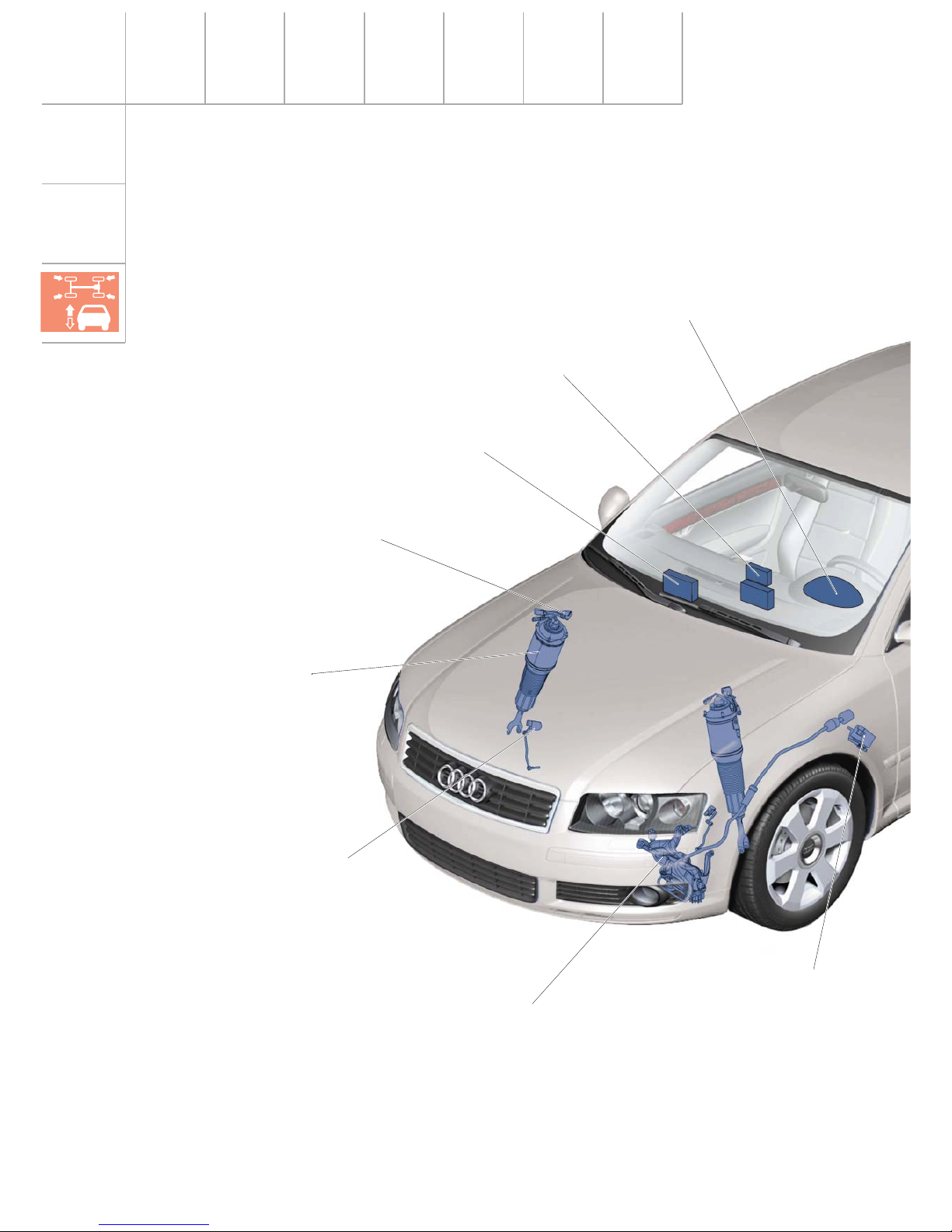
Air supply unit
Solenoid valve block
with pressure sender
Pneumatic struts, FA
Adaptive air suspension
control unit
Vehicle level
sender, FA
Dash panel insert
Front operator/display unit
(MMI)
Body acceleration
sender
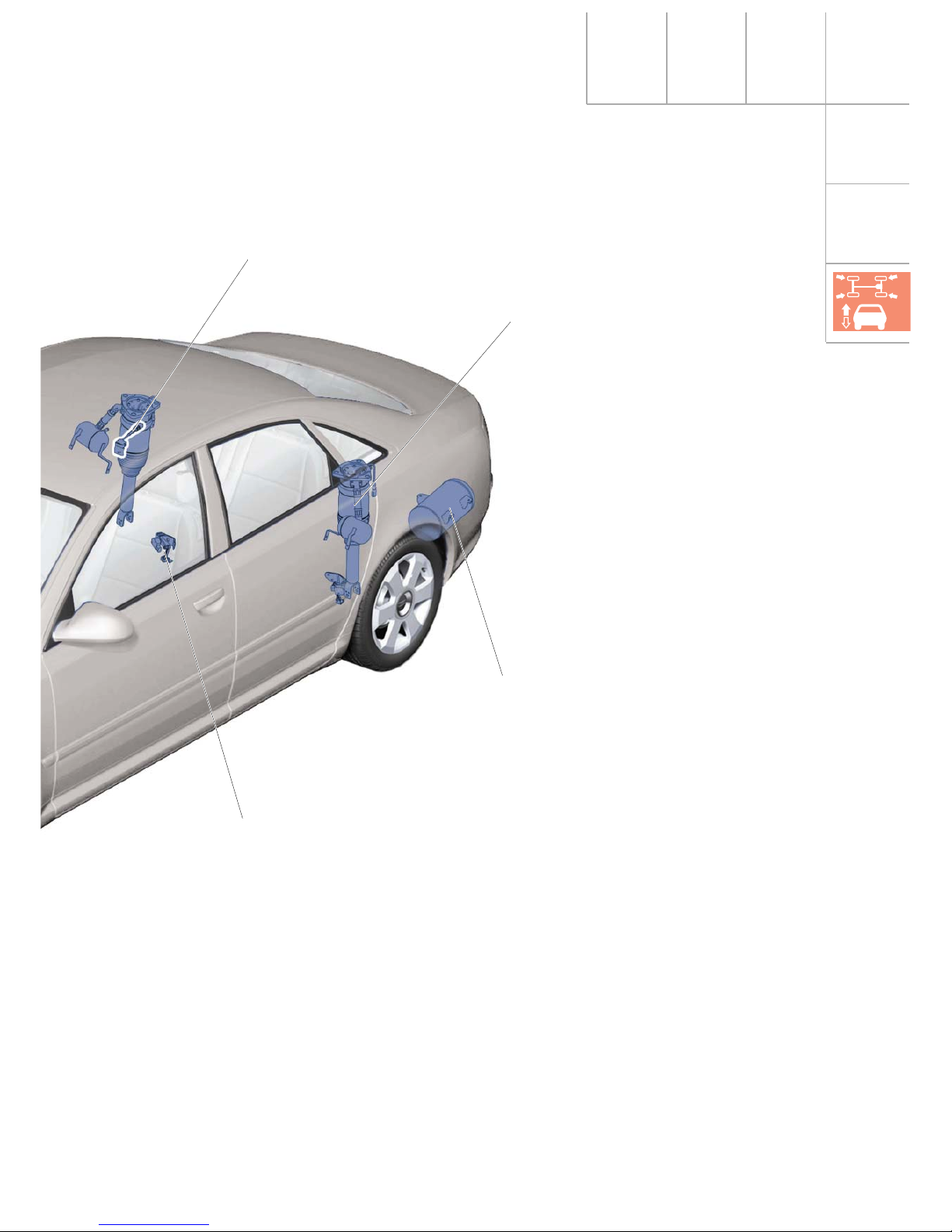
System components
Vehicle overview
11
Pneumatic struts, RA
Accumulator
Vehicle level sender, RA
Body acceleration sender
292_012
12
System components
292_013
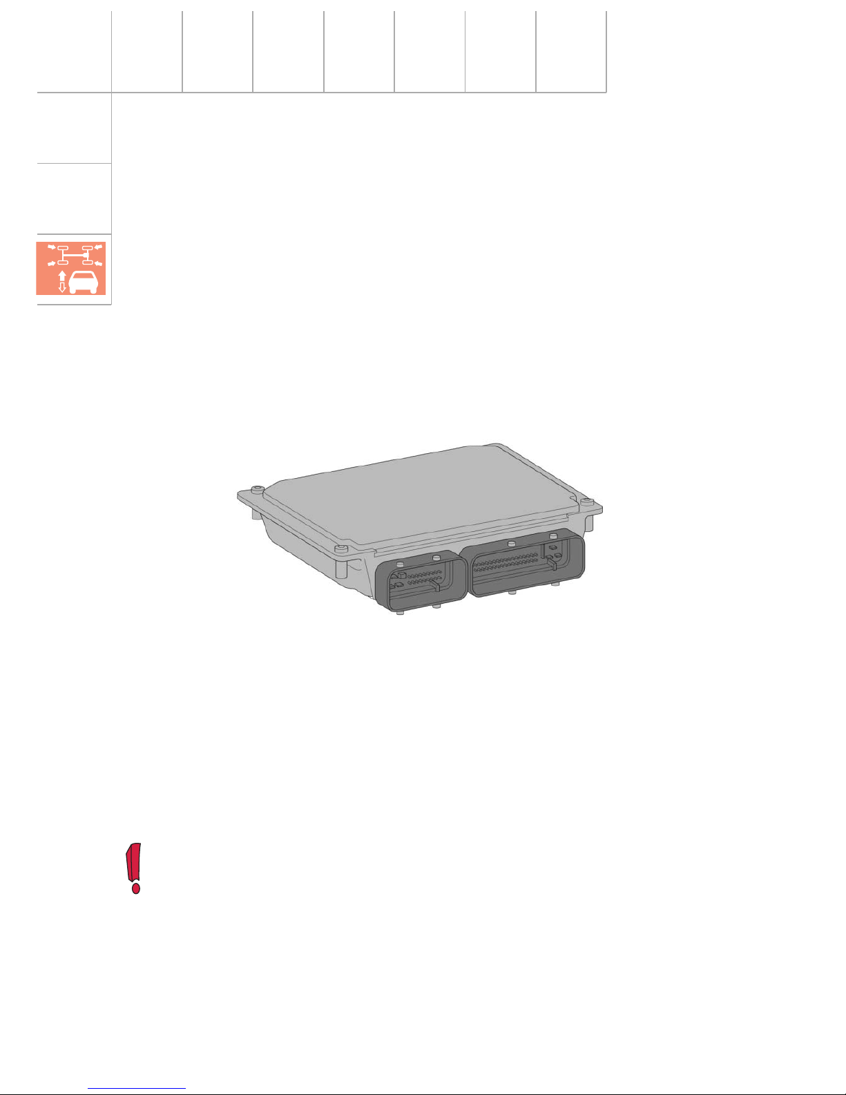
Hardware
4E0 907 553 C * = Standard running gear
4E0 907 553 D * = Sporty running gear
Control unit J197
The control unit is the central element of the
system. It is installed in the vehicle in front of
the glove box.
It processes the relevant messages from the
other bus users, and the discreet input signals (see function diagram and CAN information exchange).
The principal result of this processing work
are the signals to actuate the compressor, the
solenoid valves and the shock absorbers.
Because of the differences between the
standard and sporty running gears, the control unit had to be produced in two versions
(software application).
* These numbers are correct as at 06/2002. Changes may be made as a result of further
technical developments.
(See current Repair Manual.)
Software
4E0 910 553 C * = Standard running gear
4E0 910 553 D * = Sporty running gear

13
Pneumatic spring
Construction:
The pneumatic spring is encased in an aluminium cylinder. In order to prevent dirt from
getting between the cylinder and the air bellows, the area between the piston and the cylinder is sealed by a sleeve. The sleeve can be
replaced during servicing, but the air bellows
cannot be replaced separately. In the event of
a fault, the entire suspension/shock absorber
strut must be replaced.
In order to provide as much usable space and
loading width in the boot as possible, the
diameter of the rear axle pneumatic springs is
kept to a minimum. However, if demands for
comfort are to be met, a minimum air volume
is required. The solution to this conflict is provided in the form of a reservoir for additional
air, which is connected to the shock absorber.
Suspension/shock absorber strut
All four suspension/shock absorber struts are constructed in the same way.
292_015
Suspension/
shock absorber
strut, rear axle
Additional
air volume
292_014
Aluminium
cylinder
Pneumatic
spring
Suspension/
shock absorber
strut, front axle
Function:
The pneumatic spring not only replaces the
steel spring, it also offers considerable
advantages over the steel version (see
SSP 242). Encasing the pneumatic spring in
an aluminium cylinder enables the wall thickness of the bellows to be reduced. This
results in an even more sensitive response to
bumpy roads.

14
292_016
System components
Shock absorber
Construction:
A twin-tube gas-filled shock absorber with
continuous electrical control is used (ccontin-
uous damping control =CDC shock absorber).
The main damping valve 3 in the piston 1 is
mechanically pre-tensioned by a spring 4. A
solenoid 5 is situated above the valve, and the
connecting cable is routed to the outside
through the hollow piston rod.
Function:
For general information on the function of a
twin-tube gas-filled shock absorber, see
SSP 242.
The damping force is determined to a considerable extent by the flow resistance of the
valves. The greater the flow resistance for the
oil flowing through the valves, the higher the
damping force.
Basic method of operation using bump as an example (= bump absorption):
The entire piston unit 1 is moved downwards
inside the cylinder tube 2 at speed v.
The oil pressure in the chamber below the
main damping valve 3 increases.
Current flows to the solenoid 5. The magnetic
force F
M
counteracts the spring force FF and
partially raises it.
If the sum of the magnetic force and the oil
pressure force (F
M+FP
) exceeds the spring
force F
F
, the resulting force FR opens the
valve. The amount of magnetic force can be
regulated by adjusting the amount of electrical current. The higher the electrical current,
the lower the flow resistance and thus the
damping force.
Info: The highest damping force is achieved when the solenoid is not electrically actuated.
For the lowest damping force, the solenoid must be receiving a current of approx.
1800 mA.
In emergency running mode, the solenoid is not electrically actuated. In this way, the
damping force is set to maximum, ensuring a dynamically stable driving condition.
 Loading...