

Audi A6 2005 - Electrics Service Training
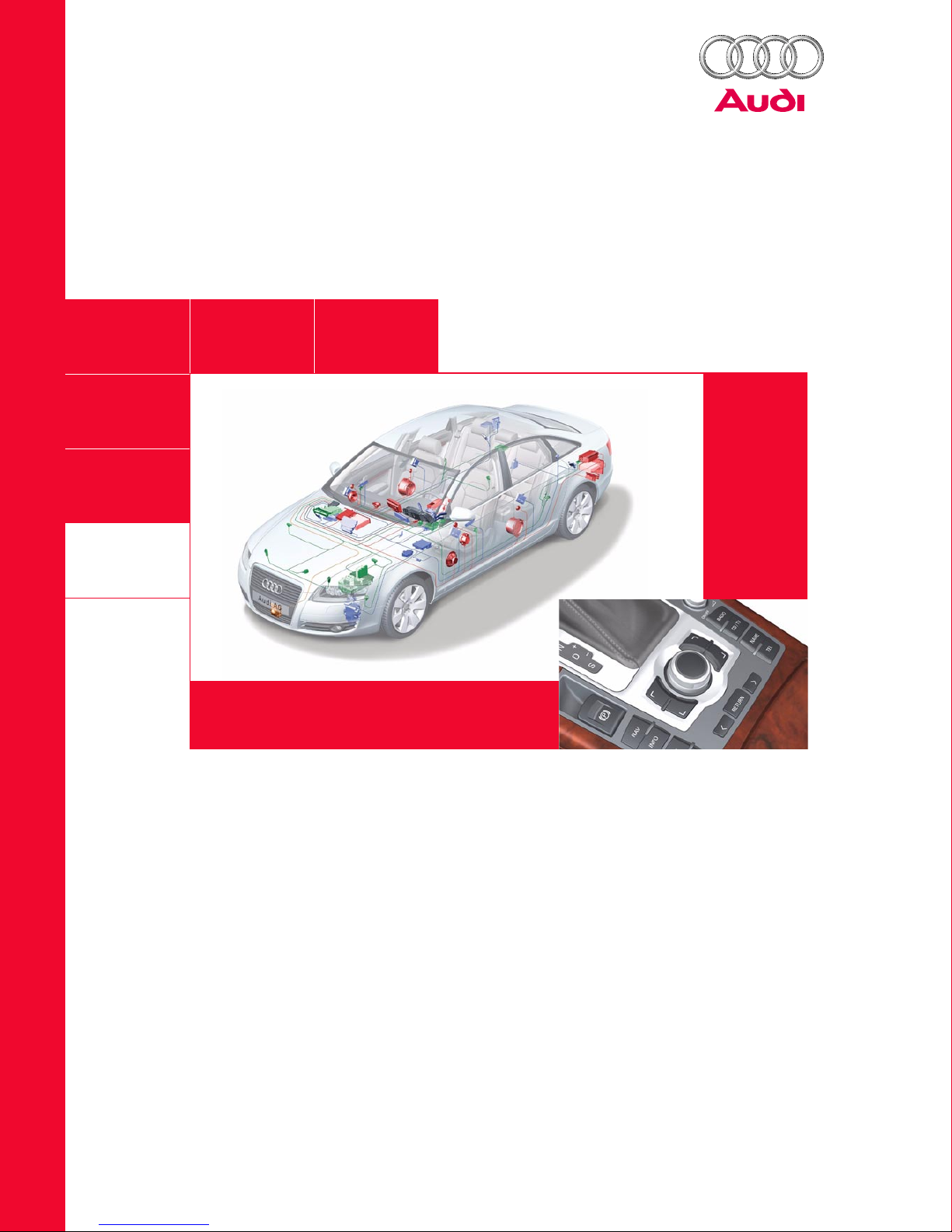
Audi A6 ‘05 – Electrics
Self-Study Programme 326
Service Training
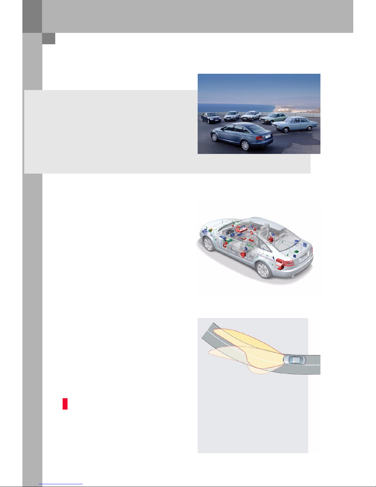
The new Audi A6 – the most progressive vehicle
takes the lead.
The new Audi A6 consistently adopts the highly
networked electronic architecture, which is already
used in the Audi A8. Overall, new technologies allow
the A6 to match up with its "model" vehicle, the Audi
A8. Features, which were previously reserved for
luxury vehicles, are now also available in the topclass segment.
In combination with these diverse capabilities,
the underlying technology has, of course,
been enhanced considerably.
The use of the most modern network technologies,
such as CAN, LIN, MOST and Bluetooth, and the
related distributed vehicle functions signals the
arrival of a new generation of vehicle electrics in
this class.
Some of these are safety-related features, such as
the combined rain/light sensor or the pivoting
cornering headlight. Comfort features of the top
class, such as the MMI operating system or
sophisticated functionalities for the mobile
baseplate, which is available ex-works, are part and
parcel of these new saloons.
The new Audi A6 has everything that is needed to
become the Number One model in the top-class
range.
It combines many different, attractive components
to form one unit. Design and performance go
hand-in-hand. The new Audi A6 will take over
as the most progressive vehicle.
The Audi A6 – the most progressive vehicle takes the lead
Number One: With Design & Performance

NoteReference NoteReference
Control unit installation positions . . . . . . . . . . . . . . . . . . . . . . . . . . . . . . . . . . . . . . . 4
Bus topology. . . . . . . . . . . . . . . . . . . . . . . . . . . . . . . . . . . . . . . . . . . . . . . . . . . . . . . . . . 6
Installation positions of fuses and relays . . . . . . . . . . . . . . . . . . . . . . . . . . . . . . . . . 8
Overview
Convenience electrics
Control unit for power management J644 . . . . . . . . . . . . . . . . . . . . . . . . . . . . . . . 10
Access and start authorisation . . . . . . . . . . . . . . . . . . . . . . . . . . . . . . . . . . . . . . . . . 13
Immobiliser and component protection . . . . . . . . . . . . . . . . . . . . . . . . . . . . . . . . . 30
External lights . . . . . . . . . . . . . . . . . . . . . . . . . . . . . . . . . . . . . . . . . . . . . . . . . . . . . . . . 32
Control unit in dash panel insert J285 . . . . . . . . . . . . . . . . . . . . . . . . . . . . . . . . . . 40
Control unit for on-board power supply J519 . . . . . . . . . . . . . . . . . . . . . . . . . . . . 42
Control unit 2 for on-board power supply J520 . . . . . . . . . . . . . . . . . . . . . . . . . . 52
Central control unit for convenience system J393 . . . . . . . . . . . . . . . . . . . . . . . . 55
Door control units J386 - J389 . . . . . . . . . . . . . . . . . . . . . . . . . . . . . . . . . . . . . . . . . 63
Control units for seat adjustment. . . . . . . . . . . . . . . . . . . . . . . . . . . . . . . . . . . . . . . 65
Infotainment
Multimedia interface . . . . . . . . . . . . . . . . . . . . . . . . . . . . . . . . . . . . . . . . . . . . . . . . . . 68
Antenna systems . . . . . . . . . . . . . . . . . . . . . . . . . . . . . . . . . . . . . . . . . . . . . . . . . . . . . 75
Control unit for front information J523. . . . . . . . . . . . . . . . . . . . . . . . . . . . . . . . . . 76
Sound systems. . . . . . . . . . . . . . . . . . . . . . . . . . . . . . . . . . . . . . . . . . . . . . . . . . . . . . . 81
Available telephone systems . . . . . . . . . . . . . . . . . . . . . . . . . . . . . . . . . . . . . . . . . . . 86
The Self-Study Programme provides information on the fundamentals of design and function of new vehicle
models, new vehicle components or new technologies.
The Self-Study Programme is not a Workshop Manual!
Specified values serve only to make the information easier to understand and relate to the software version
that was valid at the time the Self-Study Programme (SSP) was created.
For maintenance and repair work, please make sure to use the current technical documentation.
Contents
4
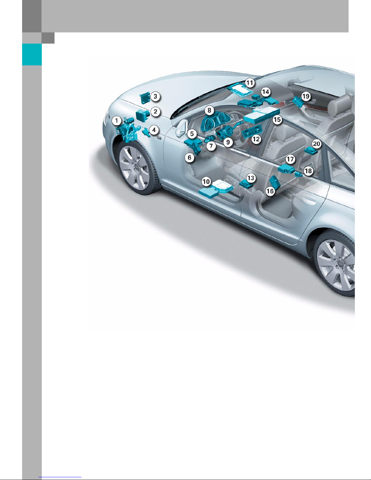
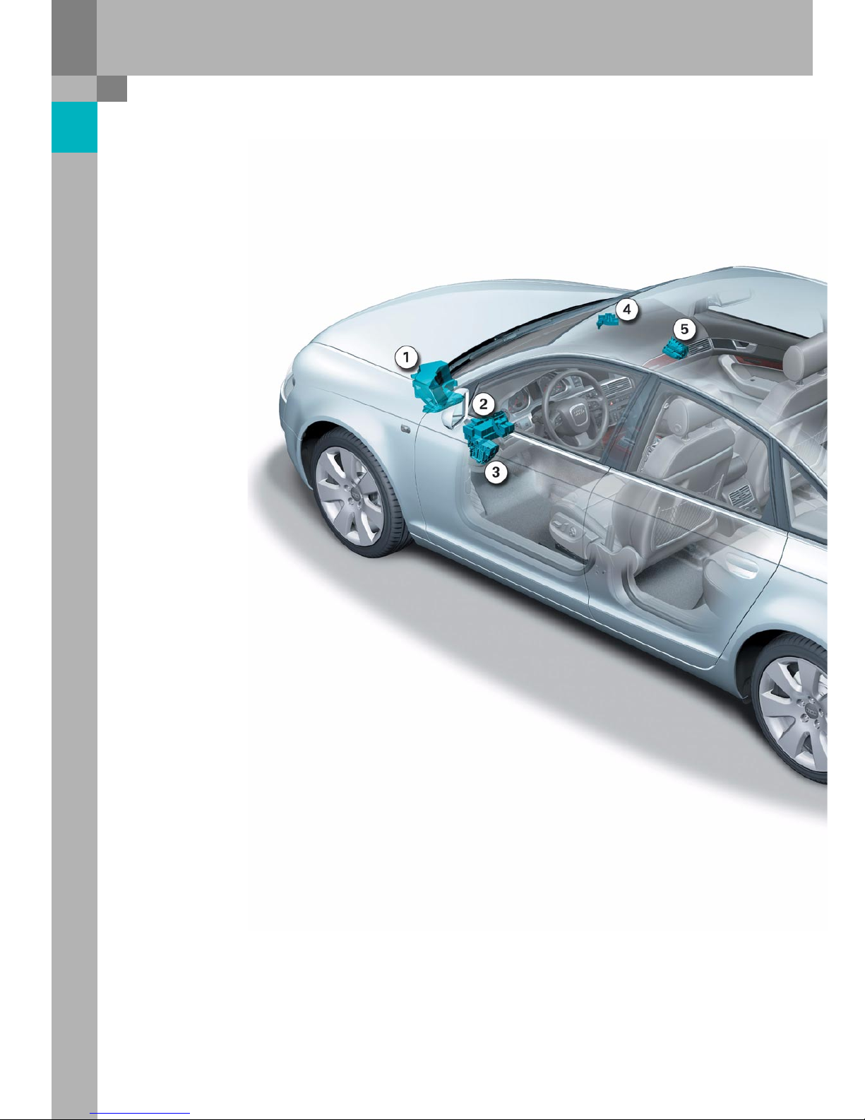
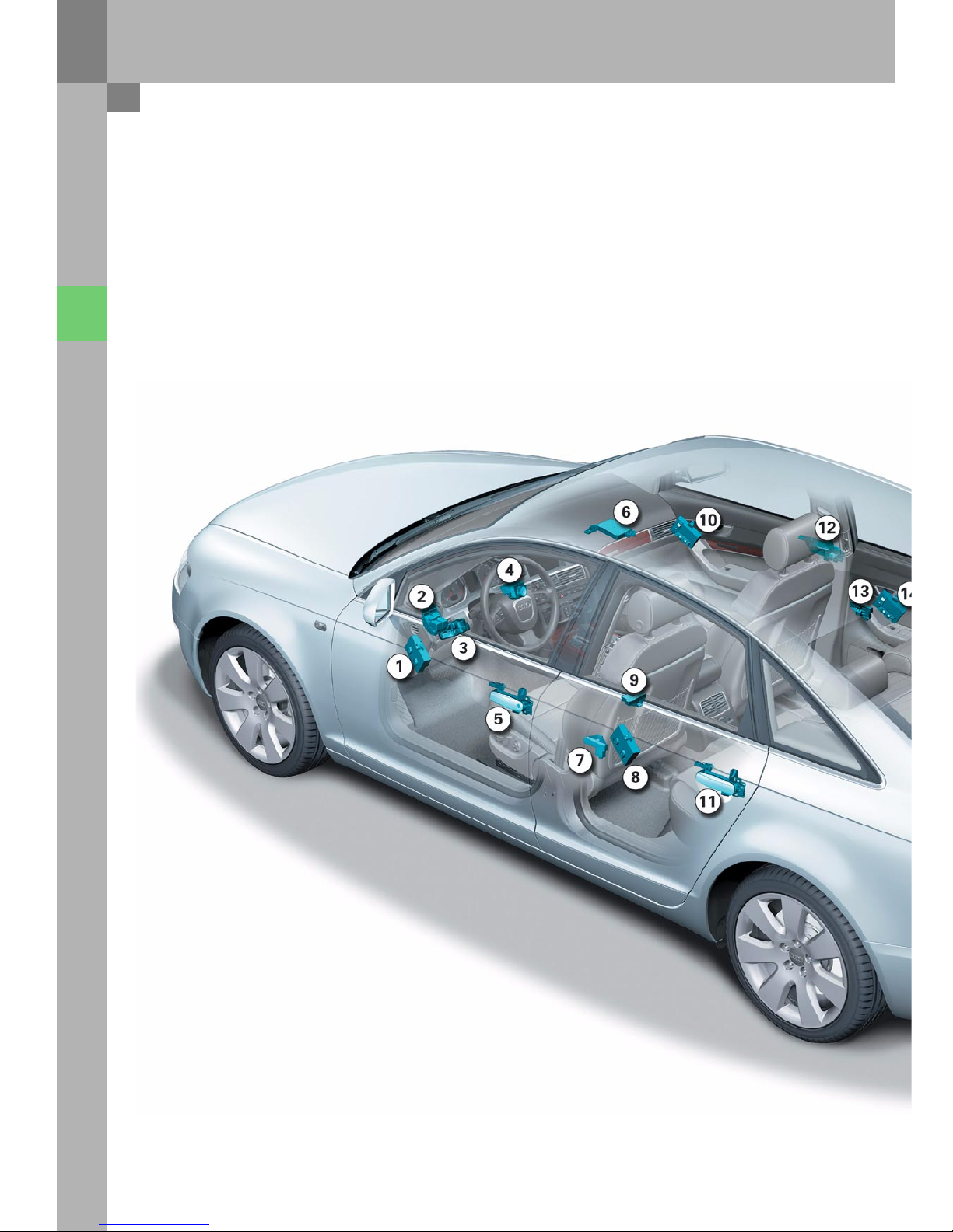
Overview
1 Auxiliary heating control unit J364
2 Control unit for ABS with EDL J104
3 Control unit for distance control J428
4 Transmitter unit in wheel well for tyre pressure
monitoring, front left G431
5 Control unit for on-board power supply J519
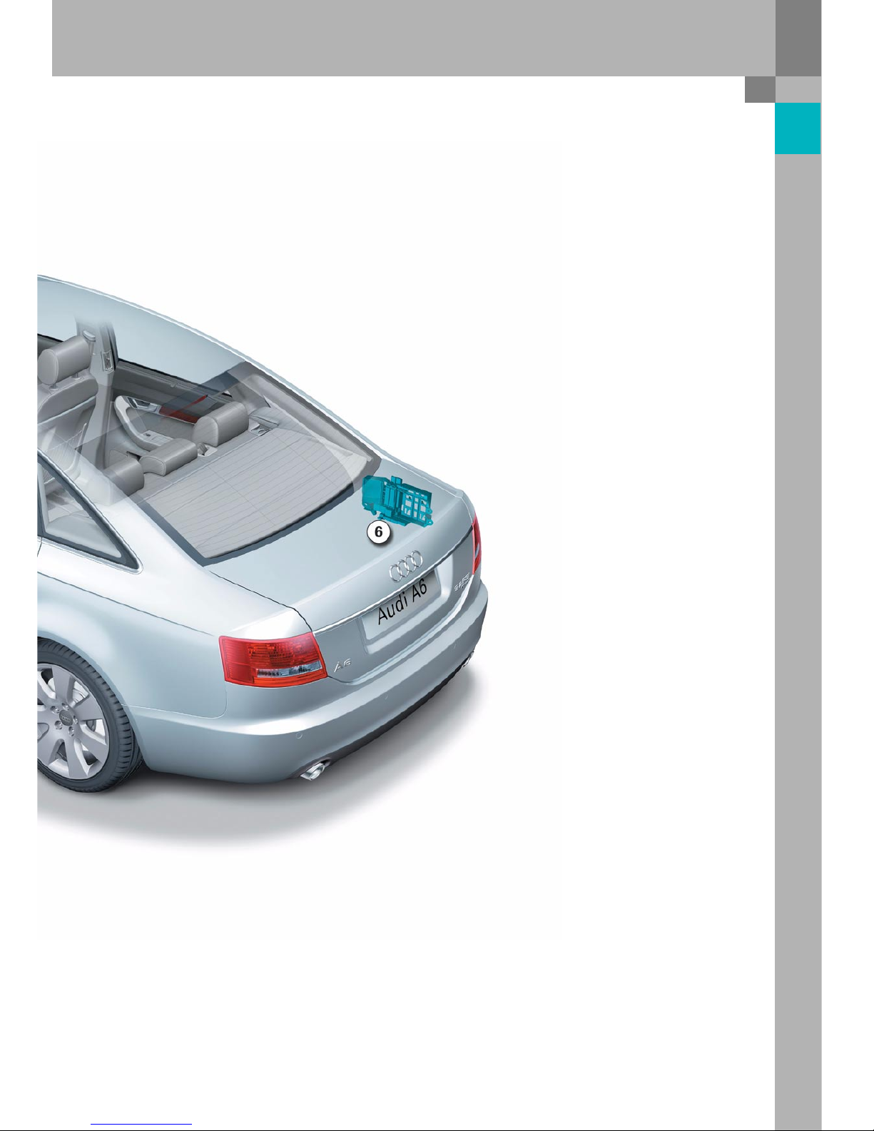
6 Door control unit, driver's side J386
7 Control unit for access and
start authorisation J518
8 Control unit in dash panel insert J285
9 Control unit for steering column electronics J527
10 Control unit for telephone, telematics J526
Telephone transmitter and receiver R36
11 Engine control unit J623
12 Climatronic control unit J255
13 Control unit for seat adjustment with steering-
column adjustment memory J136
14 Level control unit J197
Control unit for headlight range control J431
Control unit for tyre pressure monitoring J502
Control unit 2 for onboard power supply J520
Control unit for display and operating unit for
front information J523
Data bus diagnosis interface J533
Antenna read-in unit for keyless access
authorisation J723
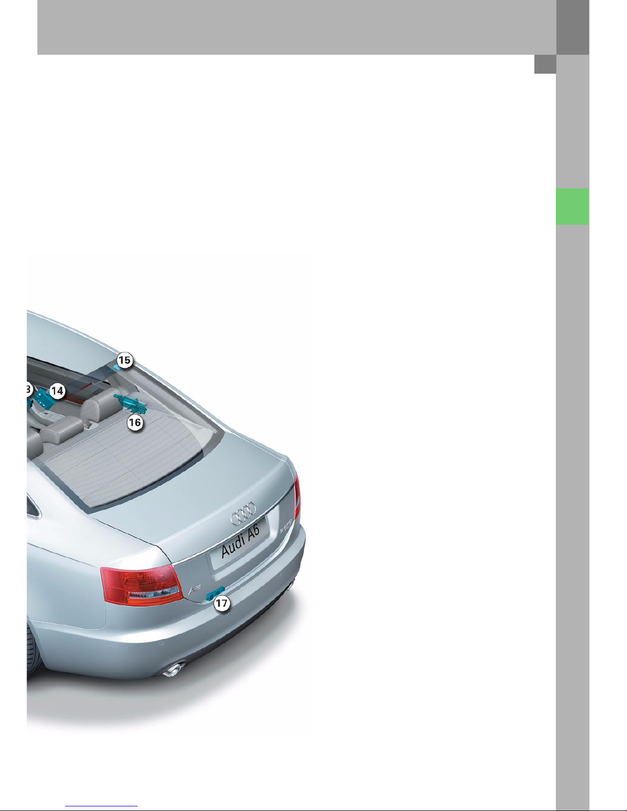
15 CD changer R41
CD ROM drive R92
16 Door control unit, rear left J388
17 Airbag control unit J234
Control unit installation positions
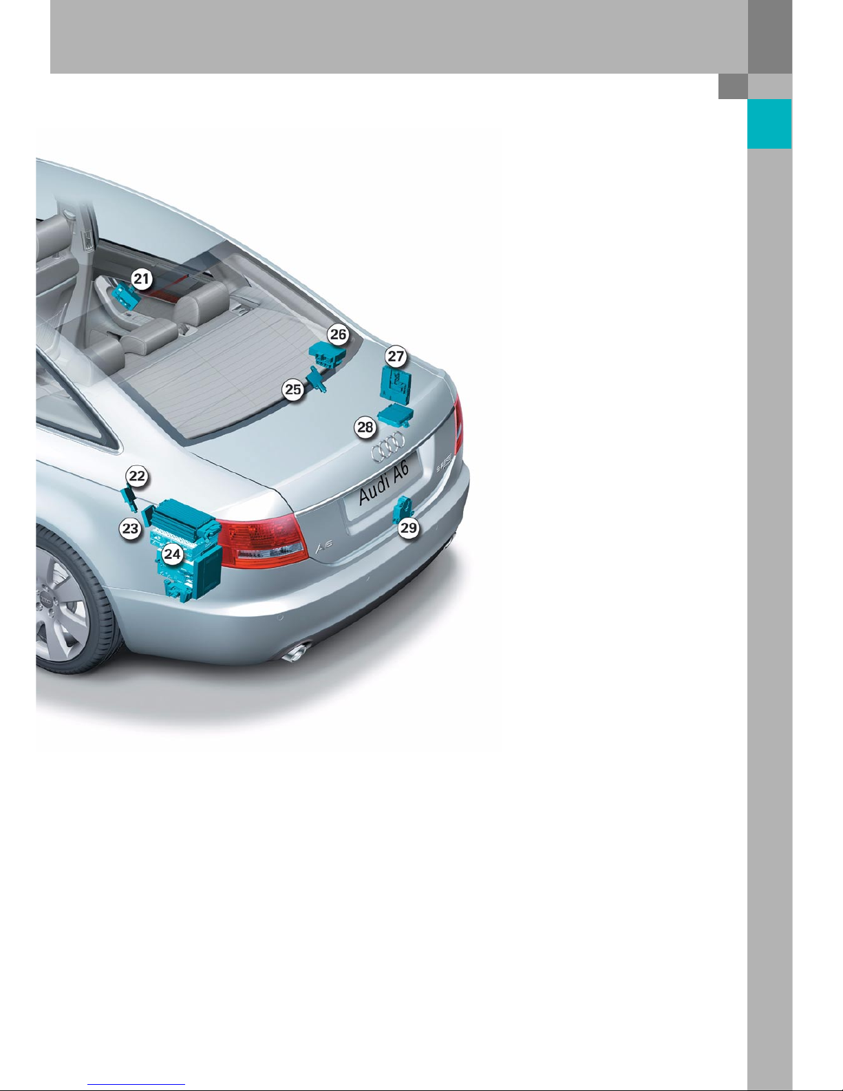
5
18 Rotation rate sensor 202
19 Door control unit, passenger's side J387
20 Control unit for seat adjustment with memory,
passenger’s side, J521
21 Door control unit, rear right J389
22 Transmitter unit in wheel well for tyre pressure
monitoring, rear left G433
23 Radio receiver for auxiliary heating R64
24 Control unit for navigation with CD drive J401
Control unit for voice input J507
Digital sound package control unit J525
Radio R
TV tuner R78
Digital radio R147
25 Transmitter unit in wheel well for tyre pressure
monitoring, rear right G434
26 Parking aid control unit J446
Control unit for trailer detection J345
27 Central control unit for convenience system J393
28 Control unit for electric parking and
hand brake J540
29 Control unit for power management J644
326_146
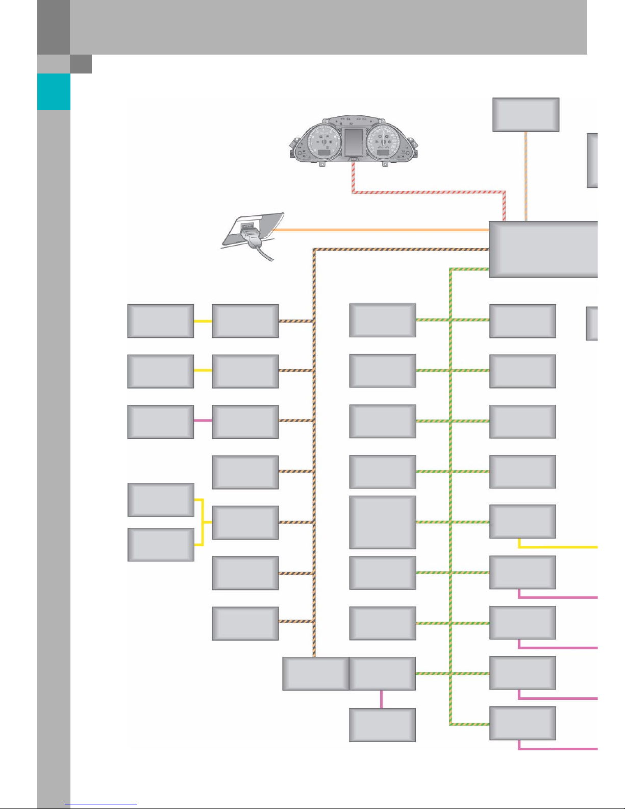
6
Bus topology
Overview
NOX sensor
J583
Rotation rate sensor
G202
Seat occupied
recognition
J706
Powe r m odule
for left headlight
J667
Powe r modu le for
right headlight
J668
Level control
J197
Electric parking
and hand brake
J540
Headlight range
control
J431
Automatic
transmission
J217
Airbag
J234
ABS with EDL
J104
Engine electronics 1
J623
Diagnosis connection
T16
Control unit in dash
panel insert
J285
Distance control
J428
Data bus diagnosis
for data bus
J533
Door control unit,
driver’s side
J386
Door control unit,
passenger’s side
J387
Door control unit,
rear left
J388
Door control unit,
rear right
J389
Seat adjustment
with memory
Steering column
adjustment
J136
Seat adjustment
with memory,
passenger’s side
J521
Trailer detection
J345
Steering column
electronics
J527
Multi-function
steering wheel
J453
Steering-angle
sensor
G85
Power management
J644
Auxiliary heating
J364
Park ing ai d
J446
On-board power
supply 2
J520
Access and
start authorisation
J518
On-board power
supply
J519
Centr. contr. unit for
convenience system
J393
Climatronic
J255
Tyre press ure
monitoring
J502
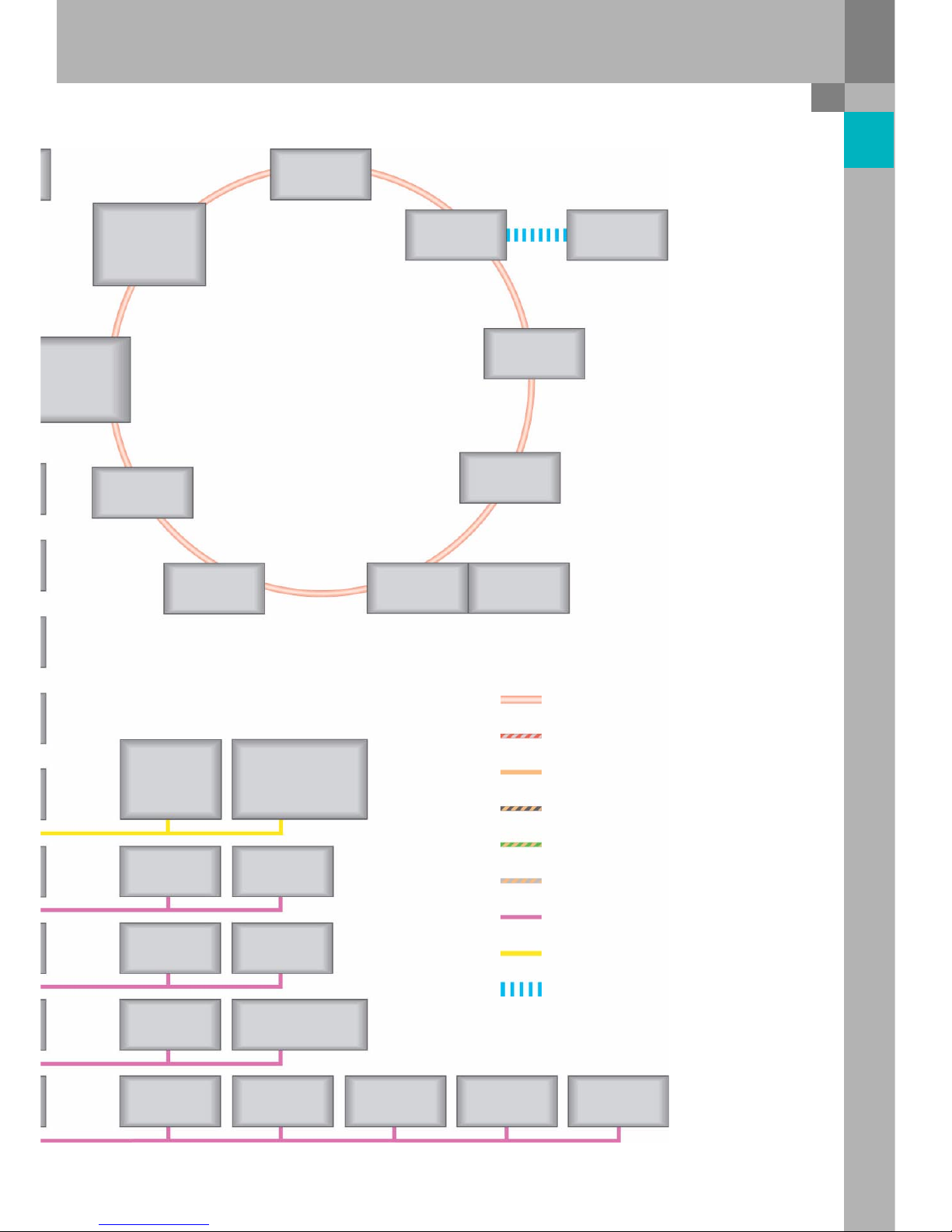
7
326_027
Display and
operating unit for
front information
J523
Te le ph o ne
transmitter and
for telephone
R36
CD changer
R41
Digital
sound package
J525
Switch for
access and
start authorisation
E415
Antenna read-in
unit for keyless access
authorisation
J723
Wiper motor
J400
Sensor for rain and
light detection
G397
Pass eng er
compartment
monitoring
G273
Alarm horn
H12
Fresh air fan
J126
Refri geran t pres sure a nd
refrigeran t temperature
G395
Tra ns mi tt er,
front left
G431
Tra ns mi tt er,
front right
G432
Tra nsm it te r,
rear l eft
G433
Transmitter,
rear rig ht
G434
Antenna, rear
R96
Te le ph o n e/
telematics
J526
Handset
for telephone
R37
Navigation
with CD drive
J401
TV tuner
R78
Radio module
R
Voice input
J507
MOST bus
CAN Instrument cluster
CAN Diagnosis
CAN Drive
CAN Convenience
CAN Distance control
LIN bus
Various sub-bus systems
Wireless transmission
– Bluetooth signal
8
Overview
Installation positions of fuses and relays
1 E box in radiator tank, left
2 Relay and fuse holder behind
dash panel, left
3 Fuse holder in dash panel, left
4 Main fuse carrier in radiator tank, right
5 Fuse holder in dash panel, right
6 Relay and fuse holder in the boot, right
9
326_148
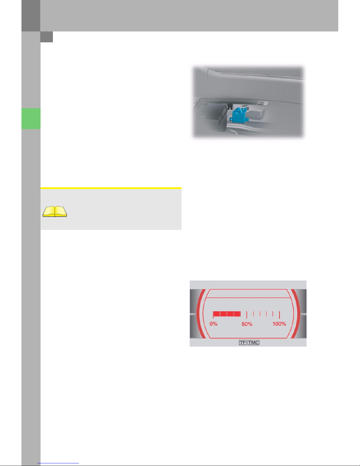
10
The basic design of the control unit for power
management is the same as the control unit used in
the Audi A8 ‘03.
It is installed in the boot well, next to the battery.
This control unit has been adapted for use in the
Audi A6 ’05 in that it now has revised software,
which shows the battery condition rather than the
battery charge level in the MMI display.
Furthermore, the diagnosis tester can be used to
read out history data, i.e. data relating to the
condition of the on-board power supply in the past.
Convenience electrics
Reference
The basic functions of the control unit for power
management J644 are described in the SSP 287.
Battery condition
The battery condition indicates how efficient the
battery is. The efficiency is determined from the
battery charge level and the ability to start.
Advantages of the battery condition:
– The cut-off stages can be allocated directly to the
battery condition.
– The messages in the central display of dash
panel insert J285 always appear for the same
battery condition reading.
– A 100 % display indicates that no cut-off stage
will be set the next time the engine is switched
off.
326_072
User Car On-board manual
Battery condition
Systems Maintenance
Control unit for power management J644
326_094
Audi
Audi A6 2005>
2005 (5)
Saloon
BBJ 3.0l Motronic / 160 kW
Guided fault-finding
Function/component selection
Selecting a function or component
Electrical system (Rep. Gr. 01; 90 - 97)
01 – Self-diagnosis systems
61 – Battery control
J644 – Control unit for power management, Functions
A – Battery, Charge level
A – Battery, Battery testing
J644 – Power management, General description
J644 – Control unit for power management, Coding
J644 – Read out history data
J644 – Power management, Read measured-value blocks
J644 – Power management, Query fault memory
J644 – Data link tests for generator voltage
J644 – Replace control unit
J644 – Power management, Activate/deactivate Transport mode
Battery change history
Data for the last three battery changes is stored.
Power balance history – driving (= engine on)
The power balance and duration of the last five
journeys are logged.
Power balance history – idle (= engine off)
The power balance and duration of the last five idle
times are logged.
Other data is not relevant for Customer Service.
History data
The diagnosis tester can be used to read out
data from the control unit for power management,
which makes it much easier to analyse the on-board
power supply and the battery.
Open-circuit voltage history
If the battery open-circuit voltage is less than the
threshold values of 12.5 volts, 12.2 volts and
11.5 volts, an entry is written to the history data.
The last four entries can always be read out.
Voltage measurement starts when
– CAN Convenience is in Sleep mode and
– terminal 15 is switched off for at least 2 hours
and
– the vehicle’s power consumption is < 100 mA.
Voltage measurement ends when
– the voltage increases or
– the current increases or
– the control unit triggers Sleep mode or
– the control unit detects a new battery.
Closed-circuit current history
If the closed-circuit current exceeds the threshold
value of 50 mA, an entry is written to the history
data. The last ten entries can be read out.
Current measu rement starts w hen
– CAN Convenience is in Sleep mode and
– terminal 15 is switched off for at least 2 hours
and
– the vehicle’s power consumption is > 50 mA.
Current measurement ends when
– the current decreases or
– the control unit triggers Sleep mode.
Breakdown analysis
If the control unit for power management detects
the status "Cannot start vehicle", an entry is written
to the histo ry data.
Cut-off level history
Data for the last 15 cut-off levels is stored.
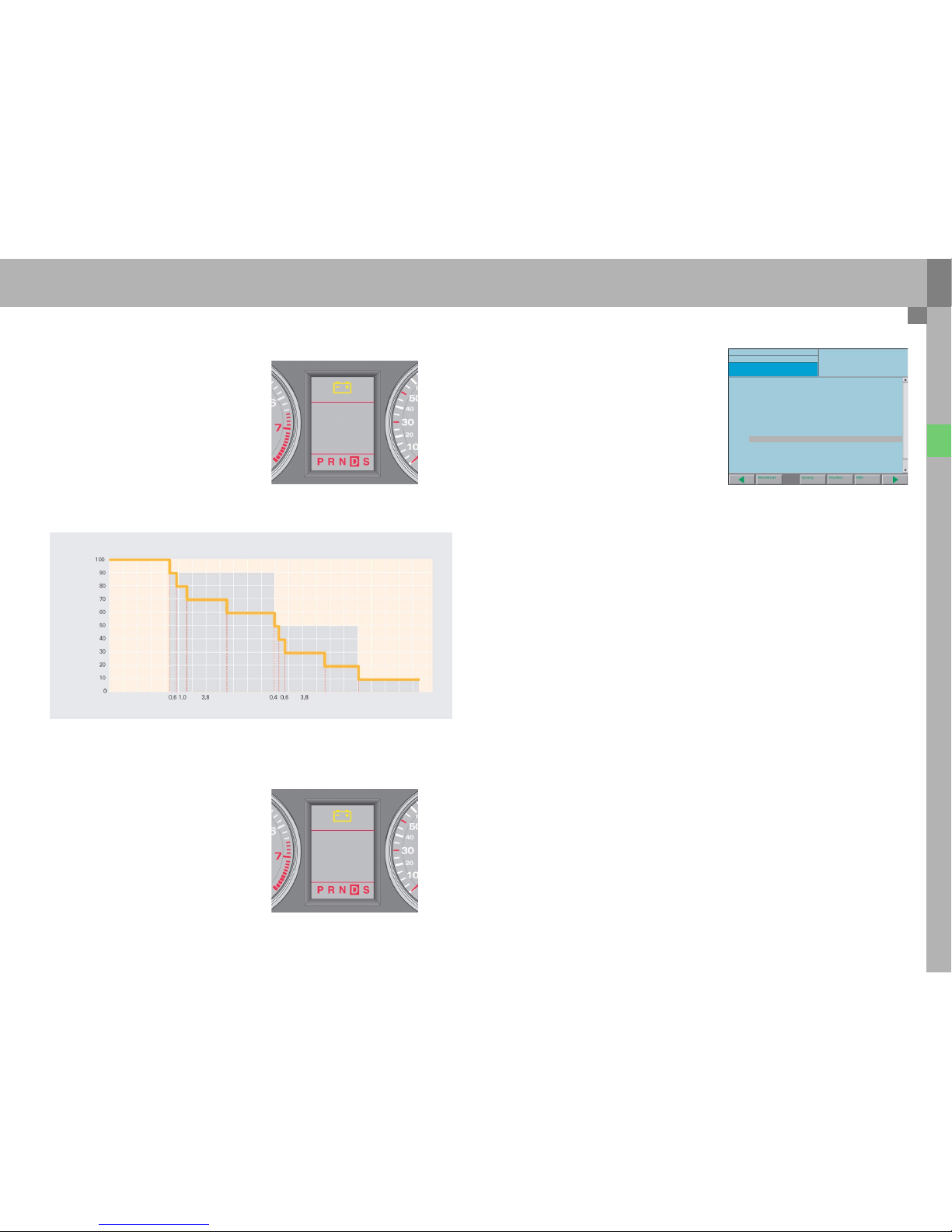
Steady battery discharge
The battery condition is 100 % when the battery is
charged.
As soon as cut-off level 1 is activated, the MMI
"Battery condition" display drops to 90 % and then
goes down to 60 % in steps. If cut-off level 1, 2 or 5
is set when the display reads 90 %, the message
"Powe r-savi ng mode active" appear s for a sho rt time
on the central display of dash panel insert J285.
In addition, the battery symbol in the dash panel
insert indicates power-saving mode for the entire
load switch-off duration.
As soon as cut-off level 3 is activated, the "Battery
condition" display drops to 50 % and then goes
down to 20 % in steps.
If the battery condition drops to 10 %, cut-off level 6
is active. In cut-off level 6, the message
"BATT ERY LOW" appe ars in the cen tral disp lay of the
dash panel insert after the ignition is switched on.
326_061
326_061
326_036
POWER-SAVING
MODE
ACTIVE
BATTERY
LOW
Battery condition
Cut-off levels 1, 2 or 5
Cut-off level 3
POWER-SAVING
MODE
ACTIVE
BATTERY
LOW
Time/M inutes
Cut-off level 6
Time/M inutes
POWER-SAVING
MODE
ACTIVE
12
326_123
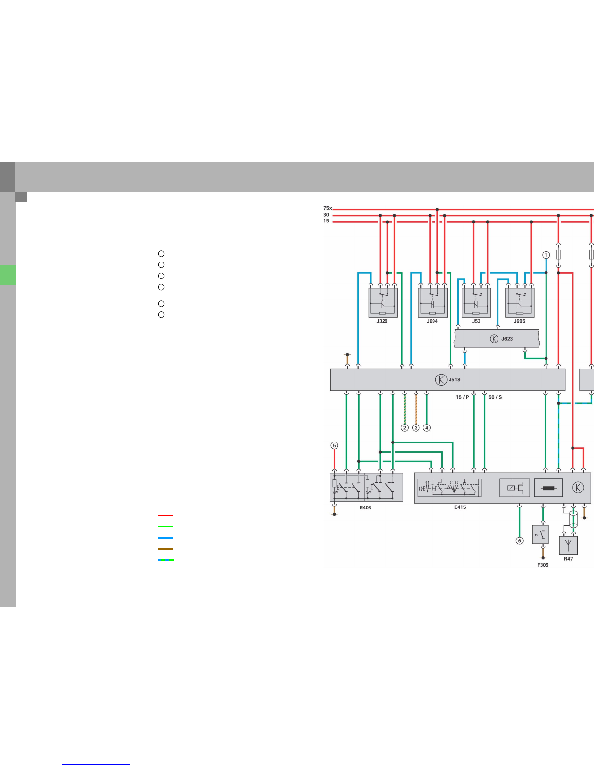
Convenience electrics
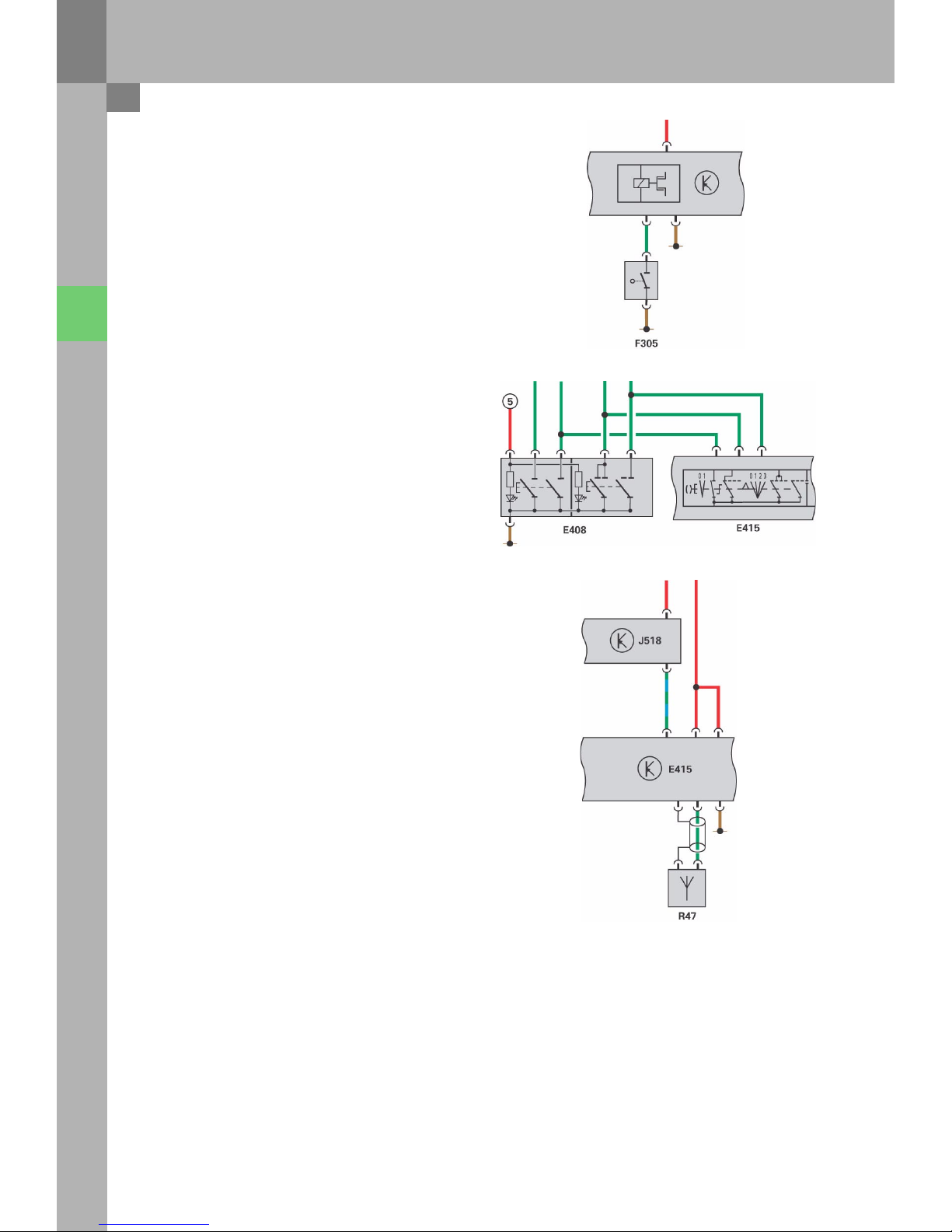
Function dia gram
Legend
E369 Central locking button for outer doo r handle,
driver’s side*
E370 Central locking button for outer doo r handle,
passenger’s side*
E371 Central locking button for outer doo r handle,
rear left*
E372 Central locking button for outer doo r handle,
rear right*
E408 Button for access and start authorisation
E415 Switch for access and start authorisation
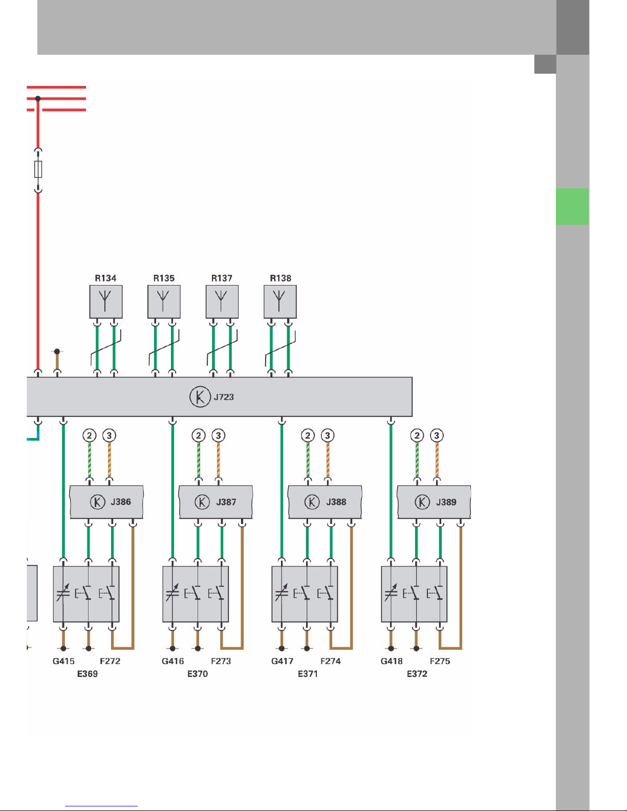
F272 Outer door handle switch, driver’s door*
F273 Outer door handle switch, passenger’s door*
F274 Outer door handle switch, rear left*
F275 Outer door handle switch, rear right*
F305 Switch for gearbox position P**
G415 Sensor for outer door handle contact,
driver’s side*
G416 Sensor for outer door handle contact,
passenger’s side*
G417 Sensor for outer door handle contact,
rear left*
G418 Sensor for outer door handle contact,
rear right*
J53 Starter relay
J329 Voltage supply relay, terminal 15
J386 Door control unit, driver's side
J387 Door control unit, passenger's side
J388 Door control unit, rear left
J389 Door control unit, rear right
J518 Control unit for access and
start authorisation
J623 Engine control unit
J694 Voltage supply relay, terminal 75x
J695 Starter relay 2
J723 Antenna read-in unit for keyless access
authorisation*
R47 Antenna for central locking and
anti-theft warning system
R134 Antenna on driver’s side for access
access and start authorisation*
R135 Antenna on passenger’s side for access
access and start authorisation*
R137 Luggage compartment antenna for access
access and start authorisation*
R138 Passenger compartment antenna 1 for
access and start authorisation*
* only for vehicles with Advanced Key
** only for vehicles with automatic transmission
1 Terminal 50 (to starter B)
2 CAN Convenience High
3 CAN Convenience Low
4 P/N signal from control unit for
automatic transmission J217**
5 Terminal 58s (lighting)*
6 Signal from brake light switch F*
Positive supply
Input signal
Output signal
Ground
Bi-directional line
13
Access and start authorisation
Start request
U
lock
15
326_038
16
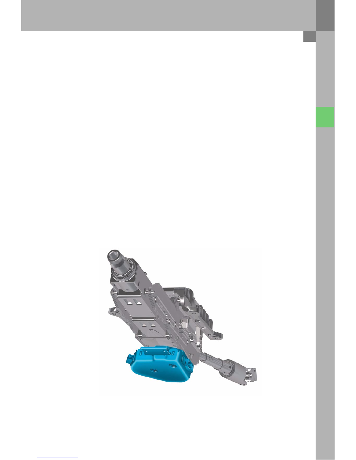
The Advanced Key system was introduced with the
Audi A8 '03 and has been fundamentally revised for
the Audi A6 ’05.
The most important new feature is that the control
unit for access and start authorisation has been
combined with the actuator for steering column
locking.
Convenience electrics
System overview
17
326_147
1 Door control unit, driver's side J386
2 Control unit for on-board power supply J519
3 Control unit for access and start
authorisation J518
4 Switch for access and start authorisation E415
5 Central locking button for outer door handle,
driver's side E369
Outer door handle switch in driver’s door F272
Sensor for outer door handle contact,
driver’s side G415
6 Antenna read-in unit for keyless access
authorisation J723
7 Antenna on driver’s side for access
and start authorisation R134
8 Door control unit, rear left J388
9 Passenger compartment antenna 1 for
and start authorisation R138
10 Door control unit, passenger's side J387
11 Central locking button for outer door handle,
rear left E371
Outer door handle switch, rear left F274
Sensor for outer door handle contact,
rear left G417
12 Central locking button for outer door handle,
passenger’s side E370
Outer door handle switch in passenger’s
door F273
Sensor for outer door handle contact,
passenger's side G416
13 Antenna on passenger’s side for access
and start authorisation R135
14 Door control unit, rear right J389
15 Antenna for central locking and
anti-theft warning system R47
16 Central locking button for outer door handle,
rear right E372
Outer door handle switch, rear right F275
Sensor for outer door handle contact, rear
right G418
17 Boot antenna for access
and start authorisation R137
18
Division of functions
System control is broken down into three basic
modules:
– the control unit for access and
start authorisation J518,
– the antenna read-in unit for keyless access
authorisation J723 and
– the switch for access and
start authorisation E415.
All three components communicate with each other
over a local single-wire bus.
The control unit for access and start authorisation is
the master of the system and a participant on
Convenience. The same control unit is installed for
all system versions.
The antenna read-in unit for keyless access
authorisation is only installed with the
Advanced Key option. It serves as the interface
between the antennae, sensors and the control unit
for access and start authorisation.
The switch for access and start authorisation is
installed in various versions, depending on the
transmission, radio frequency of the central locking
system and the Advanced Key option. An evaluation
electronic device is also integrated into the switch.
Convenience electrics
326_064
Access and
start authorisation
J518
Antenna read-in
unit for
keyless access
authorisation
J723
Switch for
access and start
authorisation
E415
19
Version s
The switch for access and start authorisation is
available in the following versions:
– with and without Advanced Key function
– with and without ignition key anti-removal lock
– for radio frequencies of 315 MHz, 433 MHz or
868 MHz
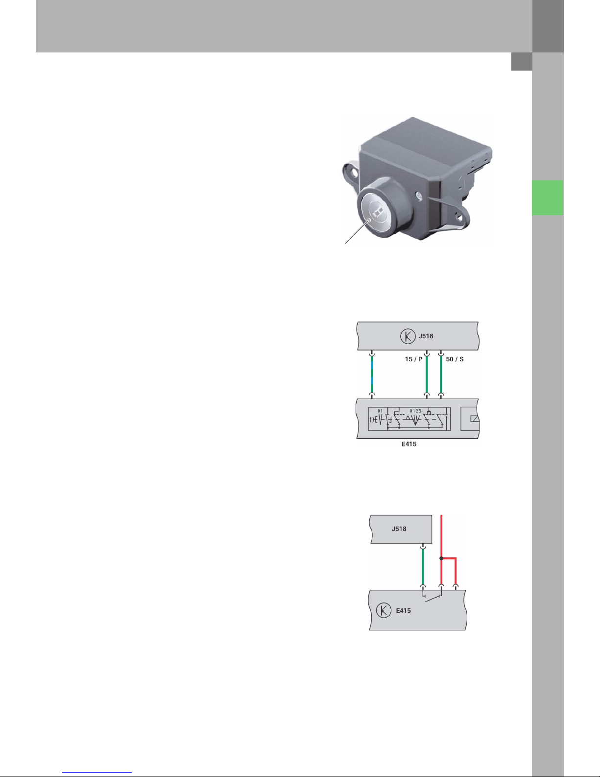
Functions
The switch for access and start authorisation
includes other functions apart from the ignition
switch function:
– Evaluation of the key position of the ignition
switch:
The ignition switch evaluates the ignition key
position using four switches.
The switch information is transferred to the
control unit for access and start authorisation in
binary code via the local bus and also for
monitoring purposes, via two lines.
The lock barrel in the ignition switch is not coded
mechanically, which means that the turning
movement can be performed with every
A6 '05 key.
– Safety branch for the steering lock of the control
unit for access and start
authorisation:
In addition to the switch-offs in the control unit
for access and start authorisation, the voltage
supply for the motor of the electromechanical
steering lock is interrupted in the switch for
access and start authorisation in order to
prevent the steering column locking
automatically.
If terminal 15 is switched on, the voltage supply
is always switched off.
326_066
326_067
Switch for access and start authorisation E415
U
Lock
326_122
Emergency release
20
– Reading in position P of the automatic
transmission from the switch for gearbox
position P F305:
The signal is used to activate the integrated,
magnetic ignition key anti-removal lock. If the
vehicle battery is flat, the key can be removed by
pressing the mechanical emergency release.
– Reading in the information from the button for
access and start authorisation E408 (only for
vehicles with Advanced Key):
For safety re as ons, th e posi tion s of the button fo r
access and start authorisation are evaluated by
the switch for access and start authorisation.
–
– Reading in the information from the antenna for
central locking and anti-theft warning
system R47:
The switch for access and start authorisation
passes the data, which the vehicle key sends via
remote control, on to the control unit for access
and start authorisation. The control unit
evaluates the data.
– Reading in the signal from the brake light
switch F (only for vehicles with Advanced Key):
To start the vehicle using the button for access
and start authorisation, the brake pedal must be
actuated.
– Exchanging data with the key using the
integrated read coil:
If a key is inserted into the switch for access and
start authorisation (= S contact on), the
electronics system transmits electric power into
the key via the read coil. The key then sends the
key identification into the switch via the
transponder and the read coil. This sends the
information to the control unit for access and
start authorisation.
Convenience electrics
326_069
326_068
326_065
21
The electromechanical steering column lock was
integrated into the control unit for access and start
authorisation.
Functions
– Terminal control:
The control unit for access and start
authorisation puts the information about
terminal 15, 75x, 50, S and P on
CAN Convenience.
The control unit also activates the relays for
terminal 15 and 75x and passes the start request
signal on to the engine control unit.
– Locking the steering column:
The motor and gears for locking the steering
column are integrated into the control unit for
access and start authorisation.
The position of the lock is checked using two
integrated micro switches. Terminal 15 is only
switched on after the steering is unlocked fully.
– Immobiliser and component protection:
The control unit is the master for these
functions.
Control unit for access and start authorisation J518
326_095
22
– CAN Communication:
The control unit is a participant on
CAN Convenience. Data exchange between all
the components of the access and start
authorisation system is performed via the
control unit.
It is also the diagnosis interface for the
components involved. All data, e.g. code,
immobiliser data, etc. is stored in the control unit
for access and start authorisation.
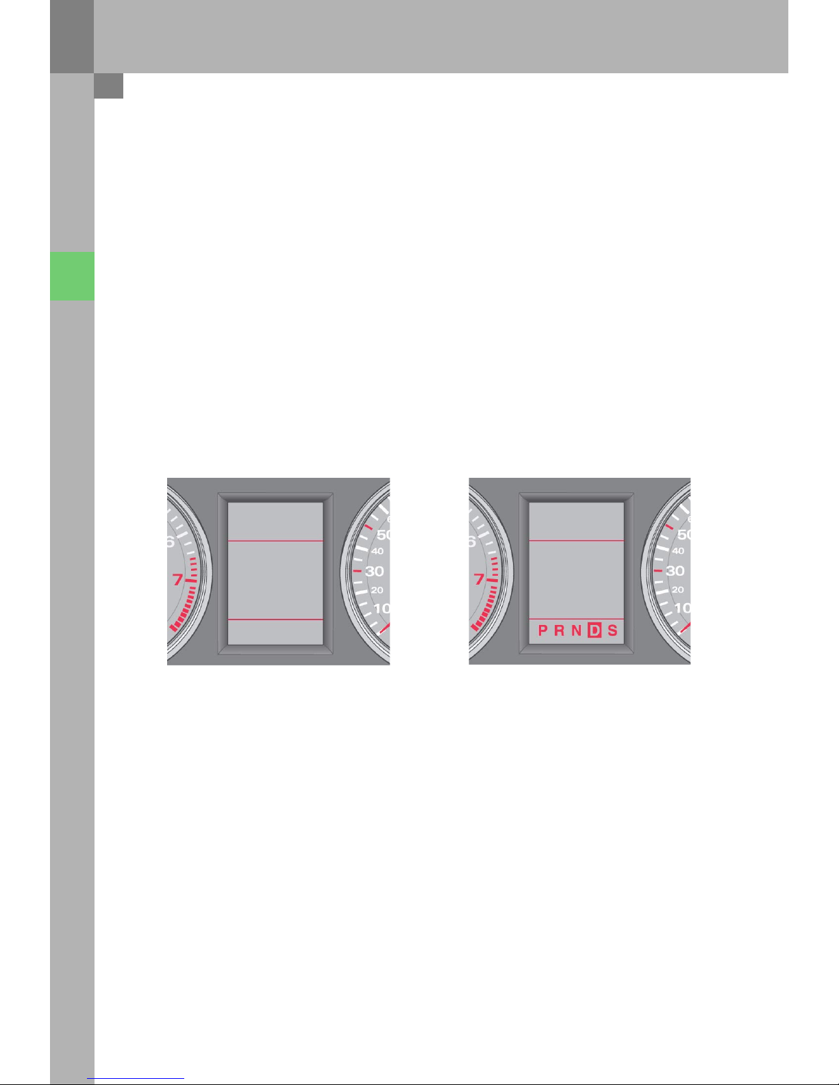
– Reading in the P/N signal from the control unit
for automatic transmission J217:
The signal is used to activate the displays
relating to engine start in dash panel insert J285.
Convenience electrics
326_062 326_063
SELECT
N OR P
TO START
THE ENGINE
SELECT
N OR P
START THE
ENGINE
23
Vehicle key
The key has a mechanically coded hinged bit for the
lock cylinder in the driver’s door and the tailgate/
boot lid. The transponder function is integrated into
the electronics and also works without a battery.
An integrated battery powers the electronics for the
radio remote control and Advanced Key functions.
A new feature here is the bi-directional data
exchange between the radio-control key and the
control unit for access and start authorisation via
the antenna for central locking and anti-theft
warning system R47. This is used to transfer the
status of the central locking system into the key.
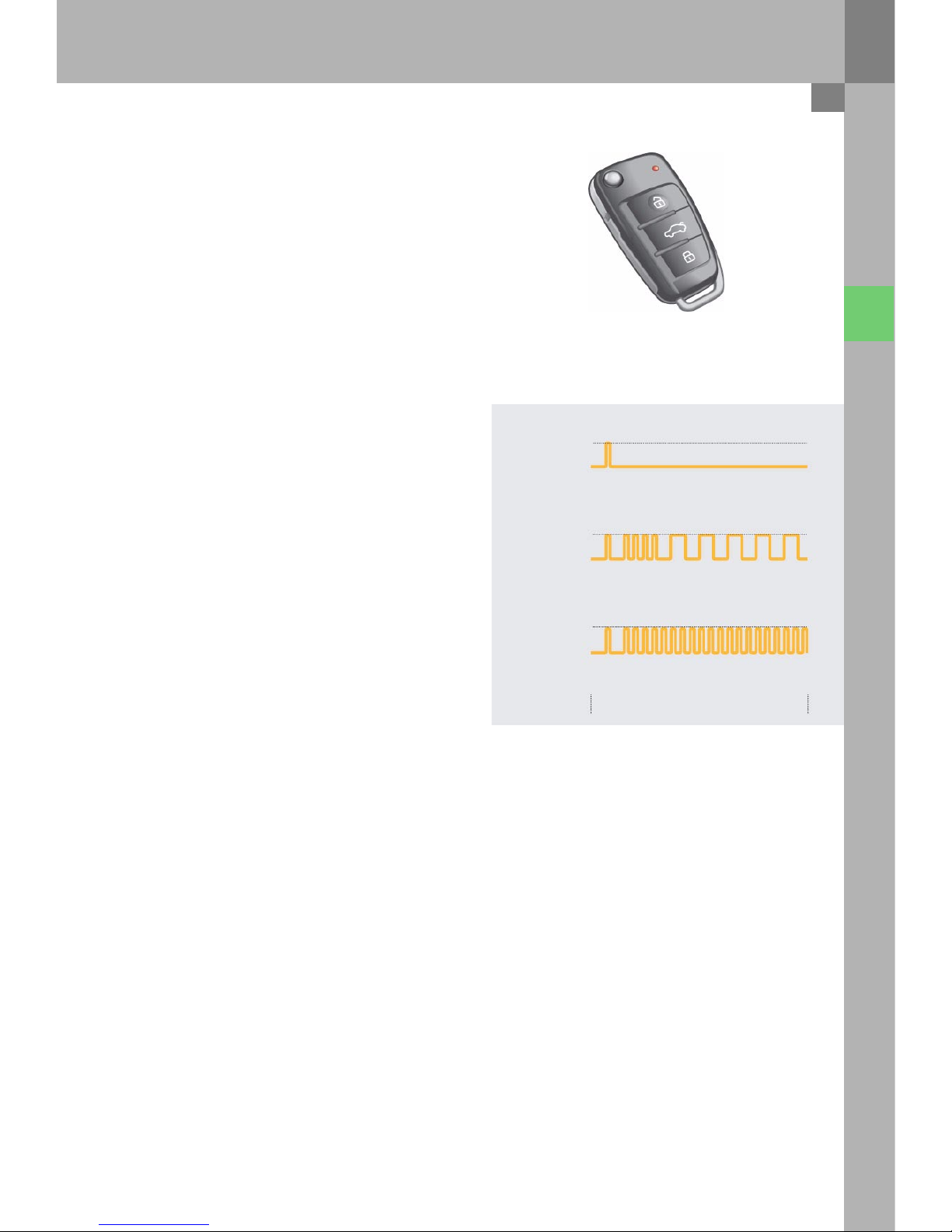
If a button outside of the function range of the key
is pressed, the LED integrated in the key shows the
lock status of the vehicle. The lock status displayed
is always the status, which was achieved using this
key when central locking was last actuated.
If the vehicle is opened or locked in the interim
period using a second key, this does not change the
lock status in the first key.
Furthermore, the radio frequency is changed from
433 MHz to 868 MHz for the first time in many
countries. This radio frequency is ideal for data
communication between vehicle keys and the
control unit.
Since this frequency can only be used for very short
transmission pulses, any interference from
long-term radio transmitters, such as baby phones,
wireless headsets, etc. is eliminated.
326_138
326_058
Vehicle within key range
Vehicle outside of key range,
last vehicle status is locked
Signals from the key LED
Vehicle outside of key range,
last vehicle status is not locked
Approx. 4 seconds
on
off
on
off
on
off
24
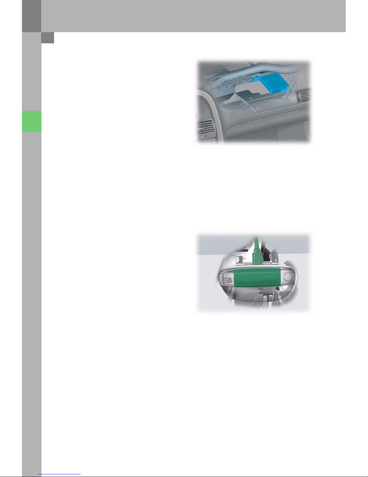
The control unit is only installed together with the
Advanced Key option.
It is located at the right of the dash panel, behind
the glove compartment.
It evaluates the signals from the outer door handle
sensors and then activates the antennae for access
and start authorisation.
The capacity-based operating sensors in the outer
door handle detect any contact on the handle and
send a signal shortly afterwards to the antenna
read-in unit for keyless access authorisation.
The antenna read-in unit evaluates the signal and
then sends a query to the vehicle key via the
antennae for access and start authorisation.
The sensors switch off after approx. 80 hours once
the vehicle is locked or after 20 actuations without
an authorised key.
Convenience electrics
326_097
Antenna read-in unit for keyless access authorisation J723
Sensors for outer door handle contact G415 - G418
326_096

25
Four transmitting antennae are distributed in the
vehicle and are used by the vehicle for radio
communication with the vehicle key. The antennae
transmit on a frequency of 24.5 kHz. The vehicle key
evaluates all four signals and determines the
position in or on the vehicle based on the field
strength of the individual antennae.
The antennae are located:
–in the rear doors
–in the centre console
–in the rear bumper
The start/stop button works in the same way as the
button module, which was first used in the A8 ‘03.
For safety reasons, the button positions are
evaluated both by the control unit for access and
start authorisation and by the switch for access and
start authorisation signal.
Antennae for access and start authorisation E134 - R138
Button for access and start authorisation E408
326_086
326_098
26
Opening the vehicle
Convenience electrics
326_055
Antenna for
central locking and
anti-theft warning
system
R47
Antenna on driver’s
side for access
start authorisation
R134
Antenna on
passenger’s side for
access start
authorisation
R135
Pass eng er
compartment
antenna 1 for start
authorisation
R138
Boot antenna for
access
start authorisation
R137
Switch for
access and start
authorisation
E415
Antenna read-in
unit for keyless access
authorisation
J723
Control unit for
access and
start authorisation
J518
Door control unit,
driver’s side
J386
Central control unit
for
convenience system
J393
Sensor for
outer door
handle contact,
driver’s side
G415

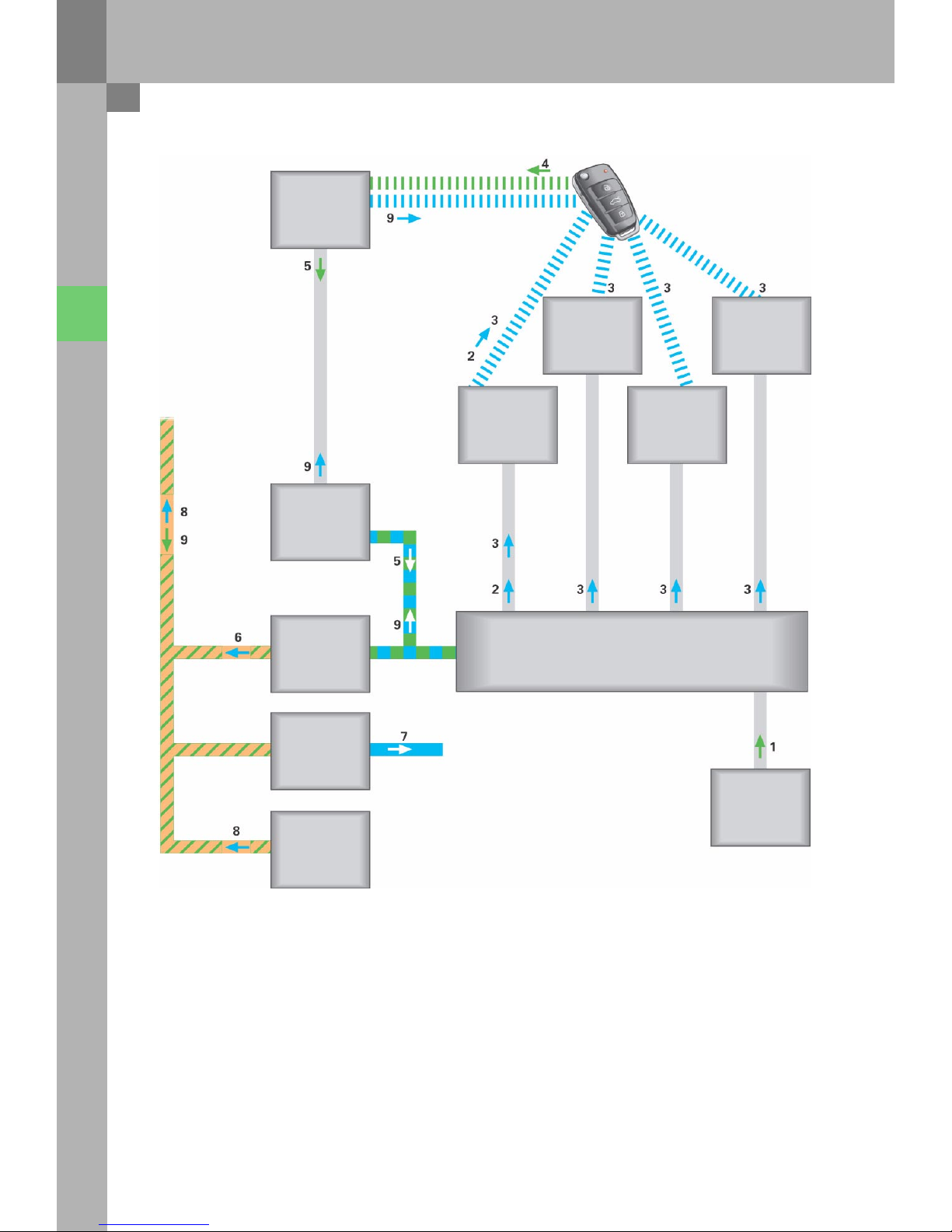
27
1 The driver puts his/her hand into the finger well
of the door handle. The sensor for outer door
handle contact G415 sends the information
"Finger in finger well" to the antenna read-in unit
for keyless access authorisation J723.
2 The antenna read-in unit sends an alarm signal
to the vehicle key via the antenna for access and
start authorisation R134.
3 The antenna read-in unit sends a signal to the
vehicle key via all the antennae for access and
start authorisation.
4 Based on the signals, the vehicle key determines
the position on the vehicle and sends
information to the antenna for central locking
and anti-theft warning system R47.
5 The antenna for central locking and anti-theft
warning system receives the information.
The information is forwarded by the switch for
access and start authorisation E415 to the
control unit for access and start
authorisation J518, where it is evaluated.
6 The control unit for access and start
authorisation sends the information "Opening
vehicle" on to the central control unit for the
convenience system J393 and to the door control
unit, whose door handle initiated the key query.
7 The door control unit, which received the
instruction from the control unit for access and
start authorisation, activates the lock unit, which
unlocks the door.
8 The central control unit for the convenience
system J393 sends the information "Opening
vehicle – Advanced Key" to CAN Convenience.
9 The normal unlocking process takes place.
This involves disarming, unlocking,
acknowledgement flashing and switching on of
the interior light. In addition to
acknowledgement flashing, the control unit for
access and start authorisation also sends the
lock status to the vehicle key via the switch for
access and start authorisation and the antenna
for central locking and anti-theft warning
system R47.
28
Starting the vehicle using the button
Convenience electrics
326_056
Antenna for
central locking and
anti-theft warning
system
R47
Antenna on driver’s
side for access
start authorisation
R134
Antenna on
passenger’s side for
access start
authorisation
R135
Pass eng er
compartment
antenna 1 for access
and start
authorisation
R138
Boot antenna for
access
start authorisation
R137
Switch for access
and start
authorisation
E415
Antenna read-in
unit for keyless access
authorisation
J723
Control unit for access
and start authorisation
J518
Data bus diagnosis
for data bus
J533
Engine control unit
J623
Button for access
and start
authorisation
J408

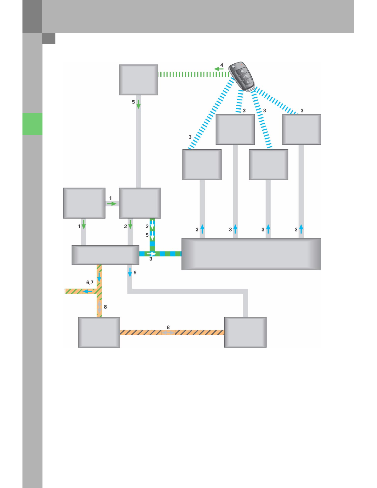
29
1 The driver presses the button for access and
start authorisation E408 down fully. The button
sends the information about "Ignition on" and
"Engine start" both to the switch for access and
start authorisation E415 and to the control unit
for access and start authorisation J518.
2 The switch for access and start authorisation
passes the information from the button on to the
control unit for access and start authorisation via
the data lead. The two button information
messages are compared there.
3 The control unit J518 sends a key query to the
antenna read-in unit for keyless access
authorisation J723.
The antenna read-in unit sends a signal to the
vehicle key via all the antennae for access and
start authorisation.
4 Based on the signals, the vehicle key determines
the position in the vehicle and sends its
information to the antenna for central locking
and anti-theft warning system R47.
5 The antenna for central locking and anti-theft
warning system receives the information.
The switch for access and start authorisation
E415 passes the information on to the control
unit for access and start authorisation, which
then evaluates it.
6 Based on the key evaluation, the S contact is
sent to CAN Convenience and the steering is
unlocked.
7 As soon as the steering is fully unlocked,
terminal 15 is switched on.
8 Once terminal 15 has been switched on, data is
exchanged between the engine control unit and
the control unit for access and start
authorisation via the CAN bus. The immobiliser is
then deactivated.
9 The control unit for access and start
authorisation sends the "Start request" signal to
the engine control unit. The engine control unit
checks whether the clutch is depressed or
whether P or N is selected in the case of an
automatic gearbox and then performs the fully
automatic engine start.
30
Immobiliser 4
Convenience electrics
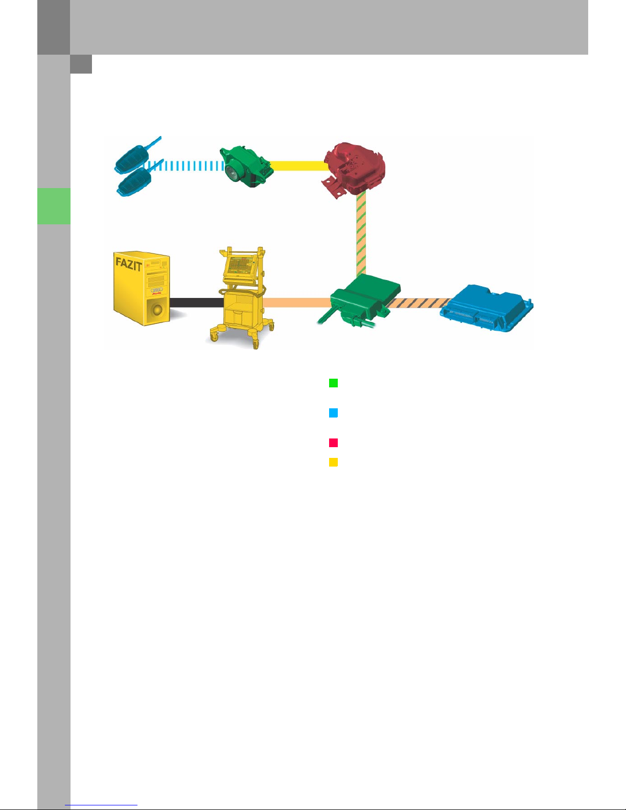
The immobiliser 4 technology is used in the
Audi A6 ’05.
This means that all components must be "taught"
online, as is already the case with the Audi A8 ´03
and the Audi A3 ´04.
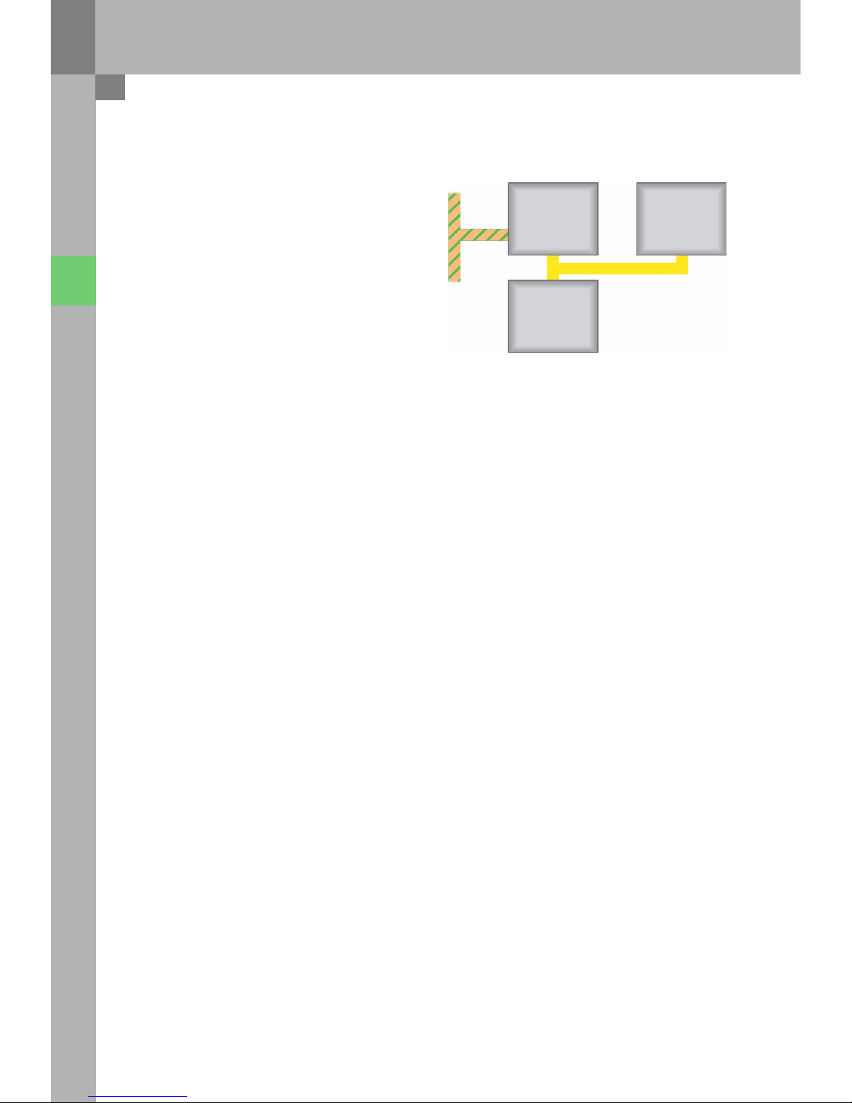
The following components are integrated into the
immobiliser:
– The control unit for access and
start authorisation
– The engine control unit
– The vehicle keys
Control unit, which is not integrated into the
immobiliser
Control unit, which is integrated into the
immobiliser
Master control unit
PC/mainframe
326_099
Immobiliser and component protection
E415 J518
J533 J623
 Loading...