

Page 1
FOREWORD
This repair manual has been prepared to provide essential information on body panel repair methods (including cutting and
welding operations, but excluding painting) for the TOYOTA
COROLLA
Applicable models: AZE141 series
ZRE142 series
This manual consists of body repair methods, exploded diagrams and illustrations of the body components and other information relating to body panel replacement such as handling
precautions, etc. However, it should be noted that the front fenders of the TOYOTA model is bolted on and require no welding.
When repairing, don’t cut and join areas that are not shown in
this manual. Only work on the specified contents to maintain
body strength.
Body construction will sometimes differ depending on specifications and country of destination. Therefore, please keep in mind
that the information contained herein is based on vehicles for
general destinations.
For the repair procedures and specifications other than collisiondamaged body components of the TOYOTA COROLLA refer to
the repair manuals.
If you require the above manuals, please contact your TOYOTA
Dealer.
All information contained in this manual is the most up-to-date at
the time of publication. However, specifications and procedures
are subject to change without prior notice.
Page 2

Page 3

ABOUT THIS MANUAL
Scope of the repair work explanation
S This text explains the welding panel replacement instructions from the vehicle’s white body condition.
We have abbreviated the explanations of the removal and reinstallation of the equipment parts up to the
white body condition and of the installation, inspection, adjustment and final inspection of equipment
parts after replacing the weld panel.
Section categories
S This manual has been divided as shown below.
Section Title Contents Examples
INTRODUCTION
BODY PANEL REPLACEMENT
BODY DIMENSIONS Body aligning measurements. Dimension diagrams.
PAINT S COATING
Explanation of general body repair.
Views of weld panel replacement instructions.
Instructions for replacing the weld panels
from the white body condition, from which
bolted parts have been removed, with
individual supply parts.
Scope and type of anti-rust treatment, etc.
together with weld panel replacement.
Contents omitted in this manual
S Make sure to perform the following essential procedures, although they are omitted in this manual.
(1) Clean and wash removed parts, if necessary.
(2) Visual inspection
Precaution
About this vehicle
Front side member replacement.
Quarter panel replacement.
Body sealer.
Under coat.
Page 4

Page 5
BODY DIMENSIONS
DI-1
Three-dimensional
distance
Two-dimensional
distance
Vertical distance
in center
A mm B mm
Center-to-center
straight-line
distance
Center-to-center horizontal
distance in forward/
rearward direction
Vertical distance
in lower surface
Imaginary Datum Line
Under Surface of
The Rocker Panel
C mm
Imaginary Datum Line
GENERAL INFORMATION
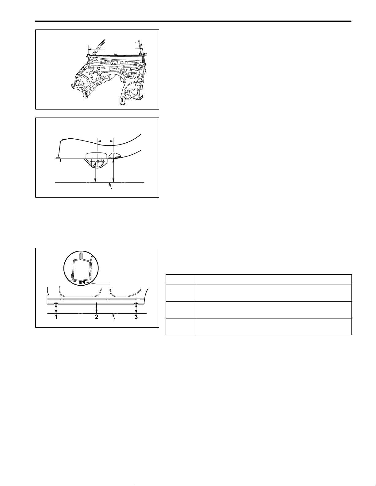
1. BASIC DIMENSIONS
(a) There are two types of dimensions in the diagram.
(1) (Three-dimensional distance)
S Straight-line distance between the centers of two
measuring points.
(2) (Two-dimensional distance)
S Horizontal distance in forward/rearward direc-
tion between the centers of two measuring
points.
S The height from an imaginary datum line.
(b) In cases in which only one dimension is given, left and right
are symmetrical.
(c) The dimensions in the following drawing indicate actual dis-
tance. Therefore, please use the dimensions as a reference.
(d) The line that connects the places listed below is the imagi-
nary datum line when measuring the height. (The dimensions are printed in the text.)
SYMBOL Name
1
2
3
The place that was lowered A mm from the under surface of
the rocker panel centered on the front jack up point.
The place that was lowered B mm from the under surface of
the rocker panel centered between 1 and 3.
The place that was lowered C mm from the under surface of
the rocker panel centered on the rear jack up point.
Page 6
DI-2
BODY DIMENSIONS
Body Looseness
Pointer Looseness
Pointer
Wrong
Pointer
Plate Looseness
Master Gauge
Correct
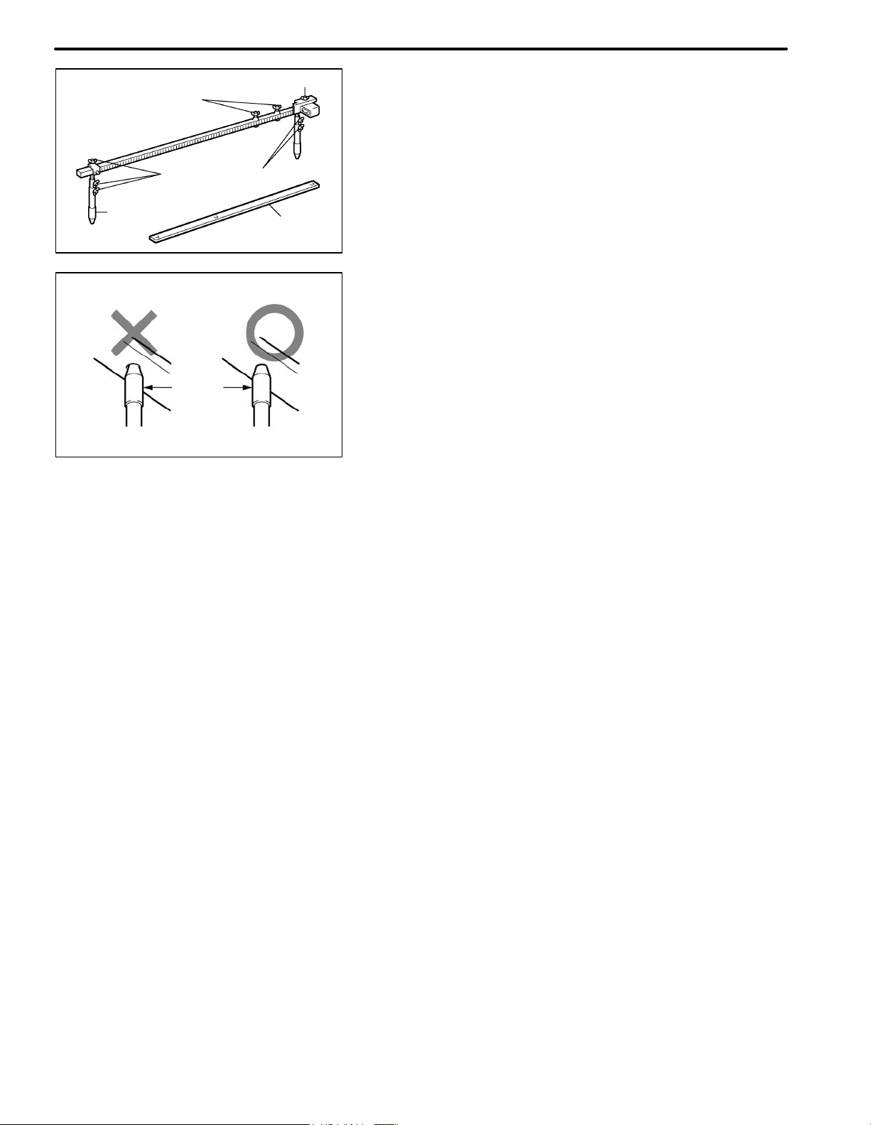
2. MEASURING
(a) Basically, all measurements are to be done with a tracking
gauge. For portions where it is not possible to use a tracking gauge, a tape measure should be used.
(b) Use only a tracking gauge that has no looseness in the
body, measuring plate, or pointers.
HINT:
1) The height of the left and right pointers must be equal.
2) Always calibrate the tracking gauge before measuring
or after adjusting the pointer height.
3) Take care not to drop the tracking gauge or otherwise
shock it.
4) Confirm that the pointers are securely in the holes.
(c) When using a tape measure, avoid twists and bends in the
tape.
Page 7
BODY DIMENSIONS DI-3
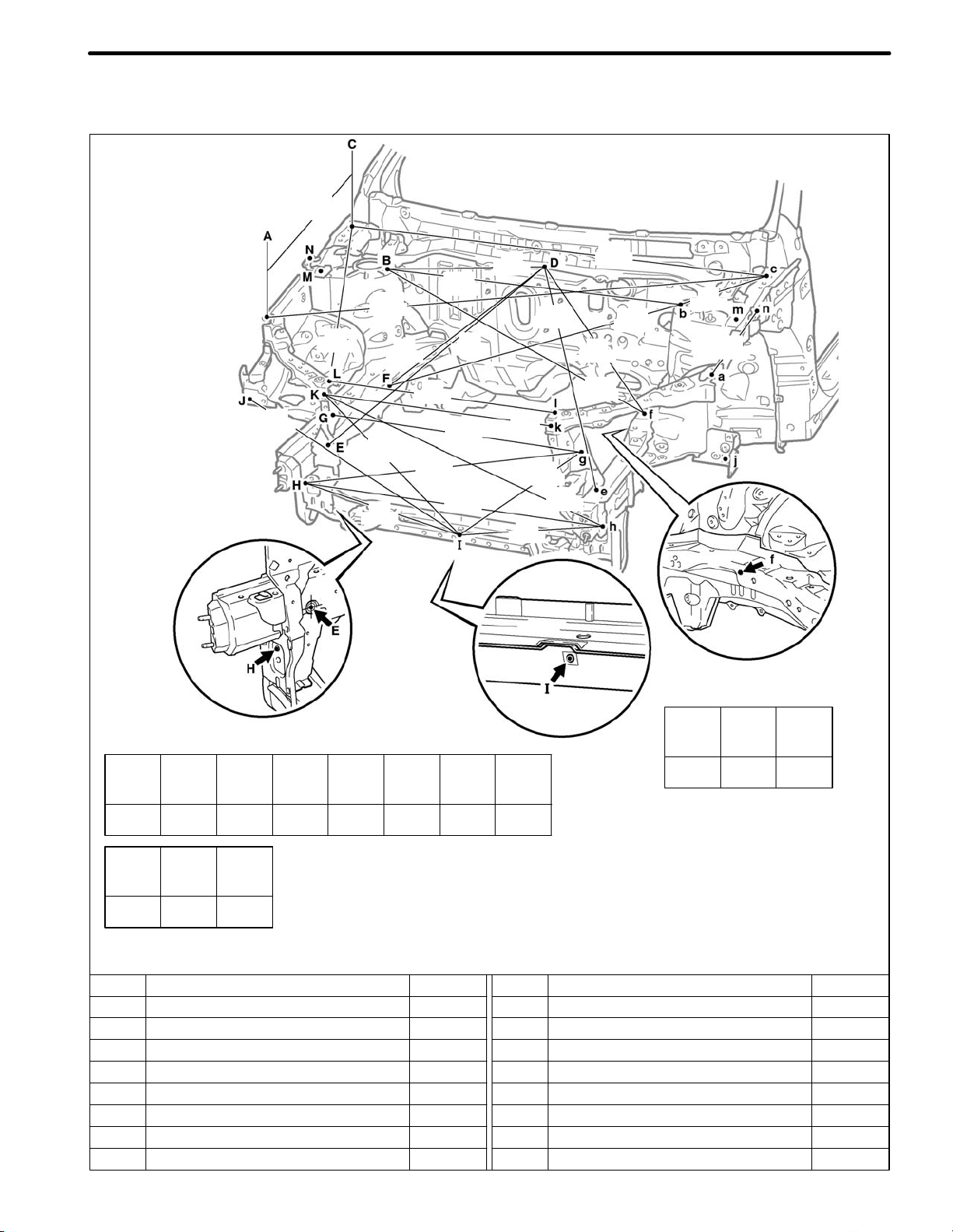
BODY DIMENSION DRAWINGS
ENGINE COMPARTMENT
(Three-Dimensional Distance)
568
(22.36)
845
(33.27)
937
(36.89)
1,575
(62.01)
592
(23.31)
501
(19.72)
638
(25.12)
728
(28.66)
929
(36.57)
1,023
(40.28)
906
(35.67)
830
(32.68)
960
(37.80)
519
(20.43)
728
(28.66)
(19.13)
(21.02)
486
891
(35.08)
534
908
(35.75)
1,456
(57.32)
604
(23.78)
1,010
(39.76)
1,038
(40.87)
269
(10.59)
339
(13.35)
Height from Imaginary Datum Line
Vehicle Dimensions
A-n B-c C-l C-M C-m
or or or or or I-j J-j M-m
a-N b-C c-L c-m c-M
1,537 1,250 1,392 263 1,457 852 1,561 1,410
(60.51) (49.21) (54.80) (10.35) (57.36) (33.54) (61.46) (55.51)
N-n or or
L-N L-n
l-n l-N
1,517 747 1,290
(59.72) (29.41) (50.79)
HINT: For symbols, capital letters indicate right side of vehicle,
small letters indicate left side of vehicle (seen from rear).
Symbol Name Hole dia.
A, a
B, b
C, c
D
E, e
F
f
G, g
Front fender installation nut
Front suspension support installation hole-inner
Hood hinge installation nut-erar
Cowl top panel center mark
Front side member standard hole
Front side member standard hole
Engin mounting installation nut
Radiator support standard hole
M6 (0.24)
ø11 (0.43)
M8 (0.31)
–
ø18 (0.71)
ø12 (0.47)
M12 (0.47)
ø10 (0.39)
A,a C,c L,l
700 783 666
(27.56) (30.83) (26.22)
mm (in.)
Symbol Name Hole dia.
H, h
I
J, j
K, k
L, l
M, m
N, n
–
Front cross member side gusset standard hole
Hood lock support brace installation nut
Front fender extension standard hole
Radiator upper support installation nut
Radiator upper support installation nut
Front apron to cowl side membe upper standard hole
Front fender installation nut
–
ø10 (0.39)
M6 (0.24)
ø10 (0.39)
M6 (0.24)
M6 (0.24)
ø10 (0.39)
M6 (0.24)
–
Page 8
BODY DIMENSIONSDI-4
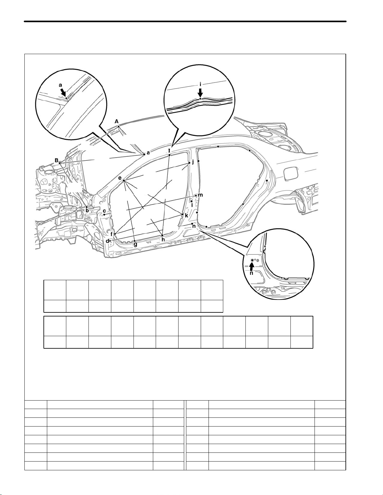
BODY OPENING AREAS (Side View: Front)
(Three-Dimensional Distance)
1,092
775
(30.51)
1,109
(43.66)
(42.99)
861
(33.90)
877
(34.53)
857
(33.74)
813
(32.01)
986
(38.82)
1,016
(40.00)
1,217
(47.91)
1,456
(57.32)
919
(36.18)
1,561
(61.46)
Vehicle Dimensions
E-e F-f G-g H-h I-i J-j K-k L-l
1,327 1,417 1,420 1,418 1,159 1,280 1,448 1,563
(52.24) (55.79) (55.91) (55.83) (45.63) (50.39) (57.01) (61.54)
E-f E-h E-i E-k F-j F-k H-i C-L C-N D-L D-M G-I
or or or or or or or or or or or or
e-F e-H e-I e-K f-J f-K h-I c-l c-n d-l d-m g-i
1,519 1,629 1,389 1,632 1,815 1,670 1,617 1,062 1,101 1,069 1,135 1,104
(59.80) (64.13) (54.68) (64.25) (71.46) (65.75) (63.66) (41.81) (43.35) (42.09) (44.68) (43.46)
HINT: For symbols, capital letters indicate right side of vehicle,
small letters indicate left side of vehicle (seen from rear).
Symbol Name Hole dia.
A, a
B, b
C, c
D, d
E, e
F, f
G, g
Roof panel corner
Hood hinge installation nut-rear
Front door hinge installation nut
Front door hinge installation nut
Front body pillar assembly mark
Front body pillar assembly mark
Rocker panel assembly mark
Ċ
M8 (0.31)
M8 (0.31)
M8 (0.31)
Ċ
Ċ
Ċ
mm (in.)
Symbol Name Hole dia.
H, h
K, k
M, m
N, n
Rocker panel assembly mark
Roof side rail assembly mark
I,i
Center body pillar assembly mark
J, j
Center body pillar assembly mark
Front door lock striker installation nut
L, l
Rear door hinge installation nut
Rear door hinge installation nut
Ċ
Ċ
Ċ
Ċ
M8 (0.31)
M8 (0.31)
M8 (0.31)
Page 9
BODY DIMENSIONS DI-5
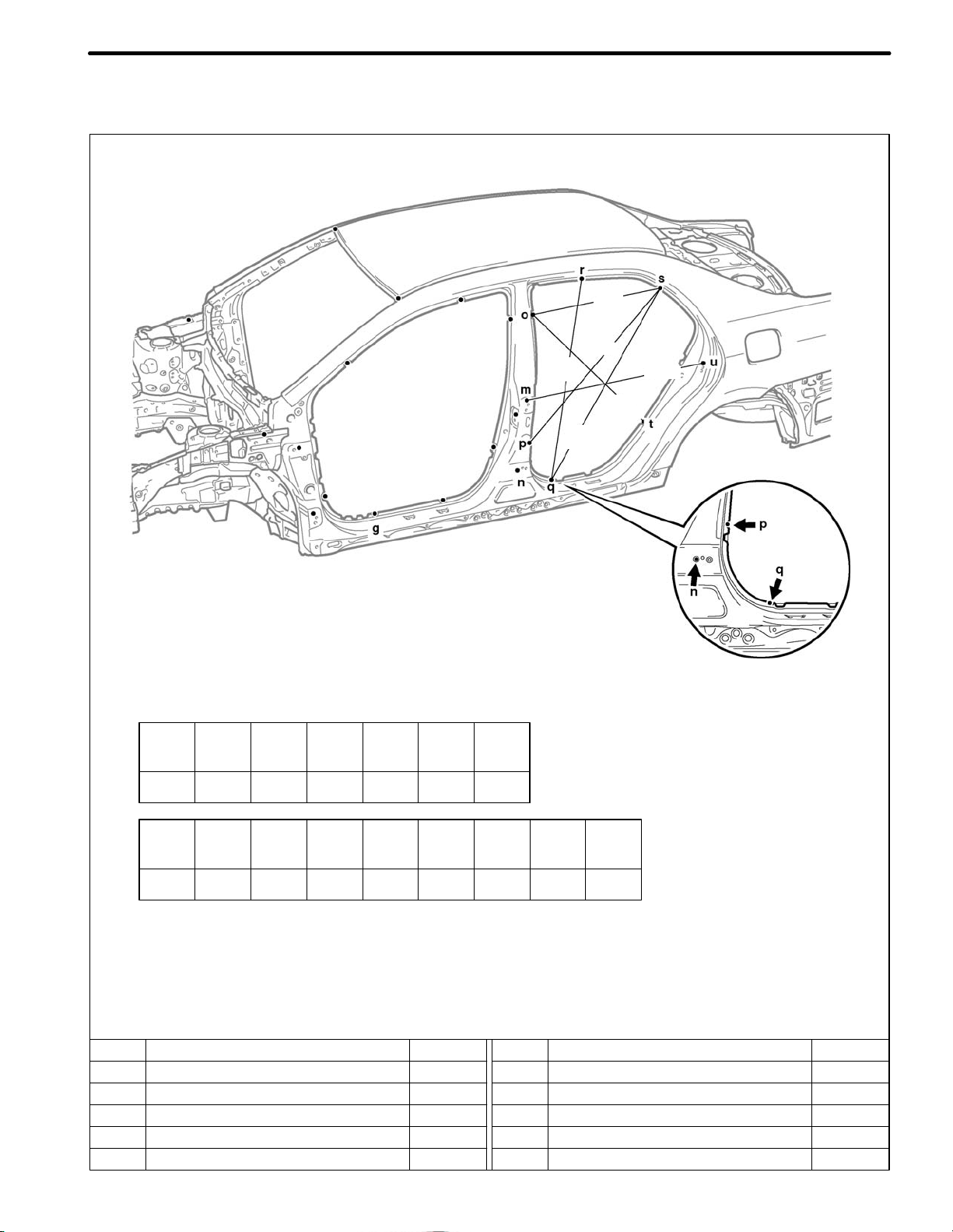
BODY OPENING AREAS (Side View: Rear)
Sedan
(Three-Dimensional Distance)
999
(39.33)
(38.62)
1,062
(41.81)
671
(26.42)
981
(32.99)
838
947
(37.28)
Vehicle Dimensions
O-o P-p Q-q R-r S-s T-t U-u
1,280 1,450 1,418 1,145 1,226 1,421 1,526
(50.39) (57.09) (55.83) (45.08) (48.27) (55.94) (60.08)
G-q O-q O-s O-t P-s P-t Q-r S-t N-U
or or or or or or or or or
g-Q o-Q o-S o-T p-S p-T q-R s-T n-u
1,702 1,603 1,421 1,588 1,656 1,559 1,619 1,478 1,066
(67.01) (63.11) (55.94) (62.52) (65.20) (61.38) (63.74) (58.19) (41.97)
HINT: For symbols, capital letters indicate right side of vehicle,
small letters indicate left side of vehicle (seen from rear).
Symbol Name Hole dia.
G, g
M, m
N, n
O, o
Rocker panel assembly mark
Rear door hinge installation nut
Rear door hinge installation nut
Center body pillar assembly mark
P, p
Center body pillar assembly mark
Ċ
M8 (0.31)
M8 (0.31)
Ċ
Ċ
mm (in.)
Symbol Name Hole dia.
Q, q
R, r
S, s
U, u
Rocker panel notch edge
Roof side rail assembly mark
Quarter panel assembly mark
T, t
Quarter panel assembly mark
Rear door lock striker installation nut
Ċ
Ċ
Ċ
Ċ
M8 (0.31)
Page 10
BODY DIMENSIONSDI-6
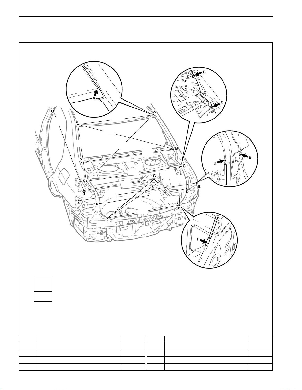
BODY OPENING AREAS (Rear View)
Sedan
(Three-Dimensional Distance)
1,035
1,240
(48.82)
(40.75)
1,200
(47.24)
Vehicle Dimensions
D-c
or
d-C
1,284
(50.55)
841
(33.11)
1,474
(58.03)
1,284
(50.55)
1,386
(54.57)
(38.74)
(46.14)
984
1,172
1,189
(46.81)
922
(36.30)
1,103
(43.43)
1,144
(45.04)
862
(33.94)
479
(18.86)
HINT: For symbols, capital letters indicate right side of vehicle,
small letters indicate left side of vehicle (seen from rear).
Symbol Name Hole dia.
A, a
B, b
C, c
D, d
Roof panel corner
Quarter panel standard hole
Quarter panel / upper back panel adjoining portion
Quarter panel end housing / Luggage compartment opening
trough adjoining portion
Ċ
13.5 x 10.5
(0.53 x 0.41)
Ċ
Ċ
mm (in.)
Symbol Name Hole dia.
E, e
G, g
H, h
Quarter panel standard hole
Quarter panel end housing/ Body lower back panel adjoining
F, f
portion
Rear suspension installation hole
Center body pillar assembly mark
ø13 (0.51)
Ċ
ø16 (0.63)
Ċ
Page 11
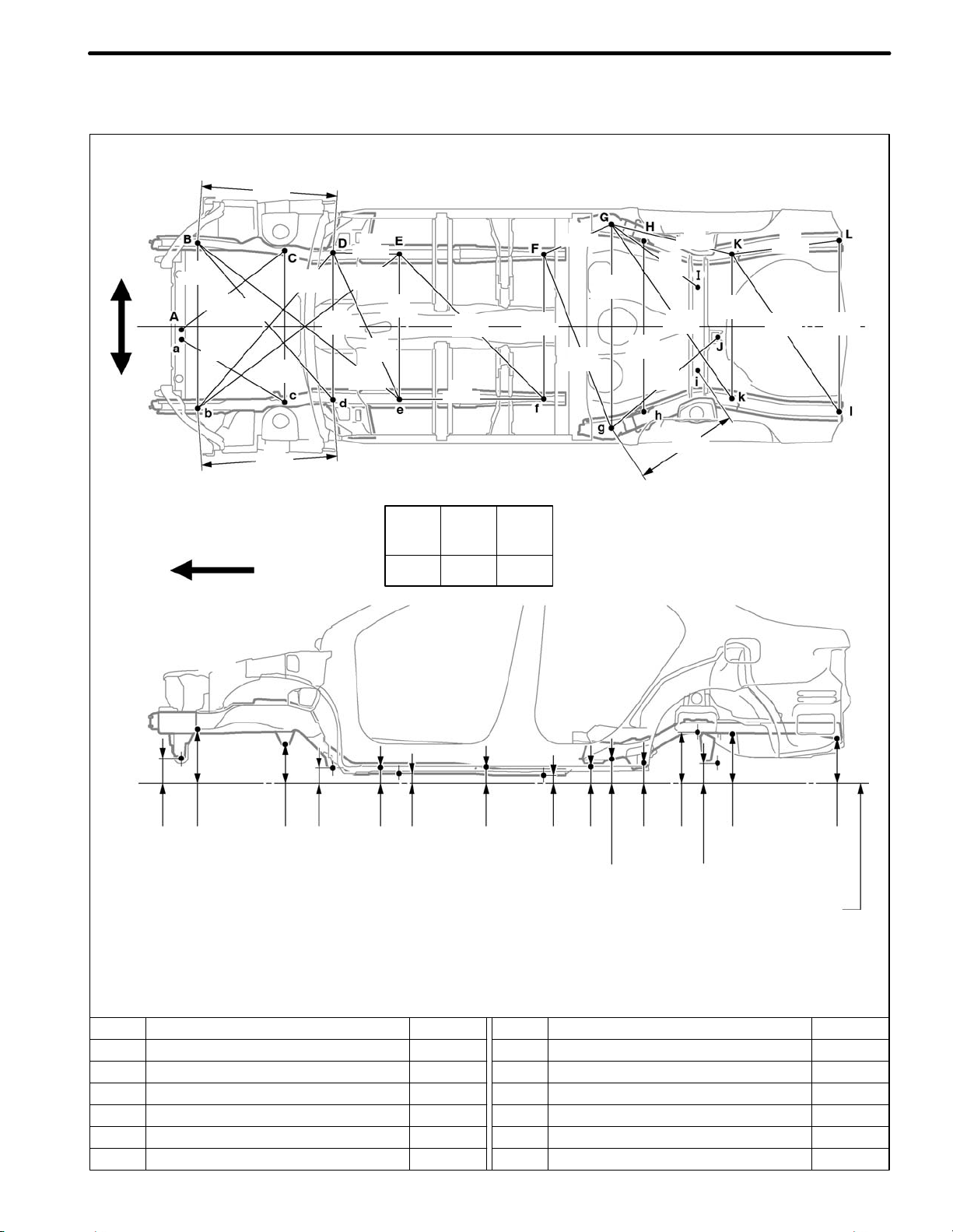
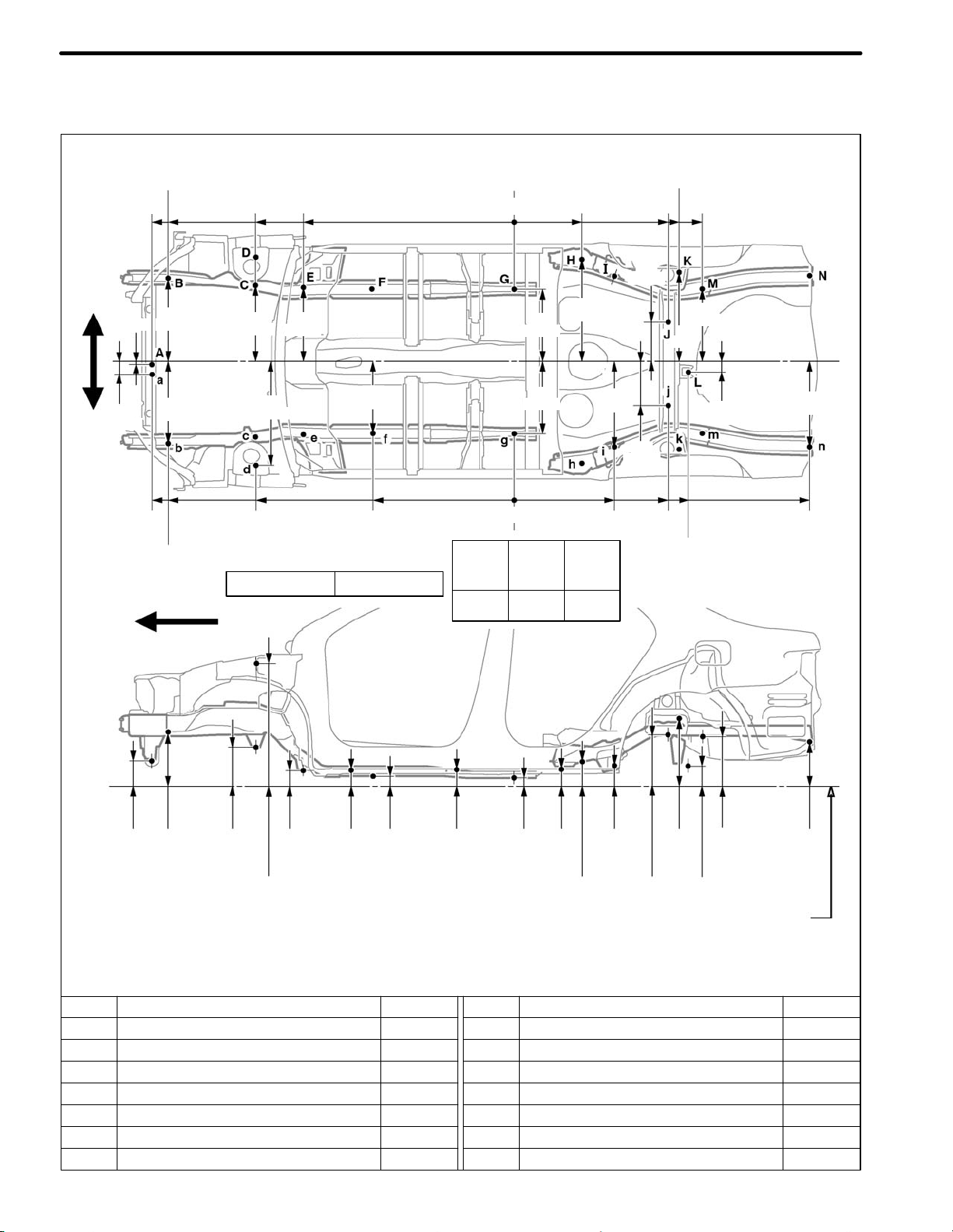
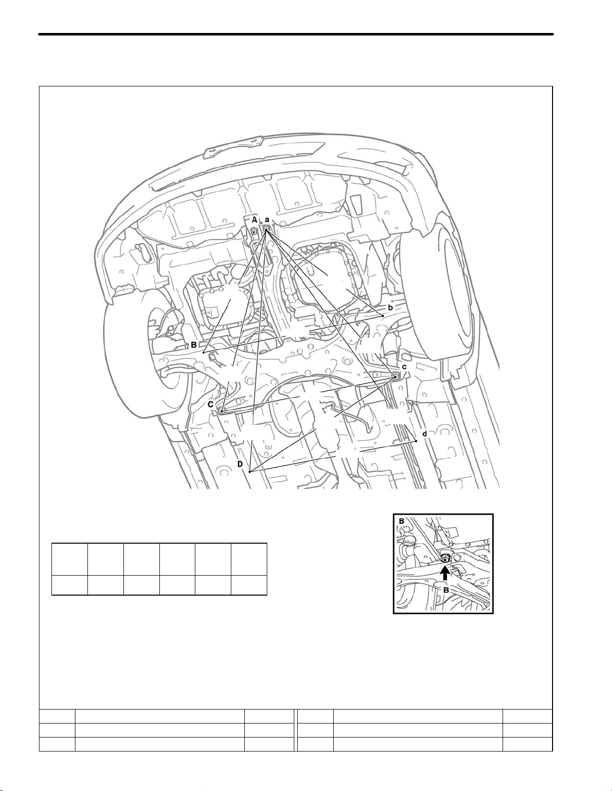
UNDER BODY
(Three-Dimensional Distance)
840
(33.07)
BODY DIMENSIONS DI-7
RH
LH
Front
985
(38.78)
(30.94)
786
730
(28.74)
1,263
(49.72)
912
(35.91)
839
(33.03)
1,252
(49.29)
890
(35.04)
400
(15.75)
1,538
(60.55)
966
(38.03)
1,547
(60.91)
870
(34.25)
1,223
(48.15)
860
(33.86)
123
100 100 100
(3.94) (3.94) (3.94)
870
(34.25)
455
(17.91)
1,129
(44.45)
1,228
(48.35)
1,035
(40.75)
656
(25.83)
1,282
(50.47)
835
(32.87)
754
(29.68)
641
(25.24)
874
(34.41)
641
(25.24)
1,147
(45.16)
1,035
(40.75)
A,a
149
(5.87)
B,b
320
(12.60)
C,c
232
(9.13)
D,d
91
(3.58)
E,e
123
57
(2.24)
HINT:
1) For symbols, capital letters indicate right side of vehicle,
small letters indicate left side of vehicle (seen from rear).
2) Point A,a, B,b, I,i on the vehicle are asymmetrical.
Symbol Name Hole dia.
A, a
B, b
C, c
D, d
E, e
F, f
Engine mounting center member installation nut
Front side member standard hole
Front suspension crossmember installation nut
Front suspension crossmember installation nut
Front side member standard hole
Front floor under reinforcement standard hole
M10 (0.39)
ø18 (0.71)
M14 (0.55)
M14 (0.55)
ø18 (0.71)
ø10 (0.39)
F, f
48
(1.89)
G,g
146
(5.75)
H,h
123
(4.84)
I,i
307
(12.09)
J
119
(4.69)
K,k
297
(11.69)
Imaginary
L,l
271
(10.67)
Datum Line
mm (in.)
Symbol Name Hole dia.
G, g
H, h
K, k
Rear floor side front member standard hole
Trailing arm installation hole
I,i
Rear floor NO. 2 crossmember standard hole
J
Rear floor centermember NO. 4 reinforcement standard hole
Rear floor side rear member standard hole
L, l
Transport hook installation hole-rear
ø25 (0.98)
ø13 (0.51)
ø10 (0.39)
ø8 (0.31)
19 x 16
(0.75 x 0.63)
ø15 (0.59)
Page 12
UNDER BODY
BODY DIMENSIONSDI-8
(Two-Dimensional Distance)
2,064
RH
LH
(3.15)
Front
2,162
(85.12)
20
(0.79)
80
2,162
(85.12)
(81.26)
500
(19.69)
485
(19.09)
2,064
(81.26)
1,542
(60.71)
456
(17.95)
626
(24.65)
1,539
(60.59)
Wheel base 2,600 (102.36)
1,258
(49.53)
445
(17.52)
435
(17.13)
860
(33.86)
407
435
(17.13)
435
(17.13)
(16.02)
614
(24.17)
512
(20.16)
599
(23.58)
0
0
123
100 100 100
(3.94) (3.94) (3.94)
(36.22)
238
(9.37)
265
(10.43)
(38.82)
920
920
(36.22)
986
1,125
(44.29)
(17.20)
536
(21.10)
1,038
(40.87)
437
67
(2.64)
517
(20.35)
1,760
(69.29)
A,a
149
(5.87)
B,b
320
(12.60)
C,c
232
(9.13)
D,d
736
(28.98)
E,e
91
(3.58)
F, f
1
57
(2.24)
HINT:
1) For symbols, capital letters indicate right side of vehicle,
small letters indicate left side of vehicle (seen from rear).
2) Point A,a, B,b, J,j on the vehicle are asymmetrical.
Symbol Name Hole dia.
A, a
B, b
C, c
D, d
E, e
G, g
Engine mounting center member installation nut
Front side member standard hole
Front suspension crossmember installation nut
Front suspension support installation hole
Front suspension crossmember installation nut
F, f
Front side member standard holet
Front floor under reinforcement standard hole
M10 (0.39)
ø18 (0.71)
M14 (0.55)
ø11 (0.43)
M14 (0.55)
ø18 (0.71)
ø10 (0.39)
2
G,g
(1.89)
3
48
H,h
146
(5.75)
I,i
123
(4.84)
J,j
307
(12.09)
K,k
404
(15.91)
L
119
(4.69)
M,m
297
(11.69)
Imaginary
N,n
271
(10.67)
Datum Line
Symbol Name Hole dia.
H, h
K, k
M, m
N, n
Rear floor side front member standard hole
I,i
Trailing arm installation hole
J, j
Rear absorber mounting member standard hole
Rear spring bracket installation hole
L
Rear floor centermember NO. 4 reinforcement standard hole
Rear floor side rear member standard hole
Transport hook installation hole-rea
ø25 (0.98)
ø13 (0.51)
ø10 (0.39)
ø15 (0.59)
ø8 (0.31)
19 x 16
(0.75 x 0.63)
ø15 (0.59)
mm (in.)
Page 13
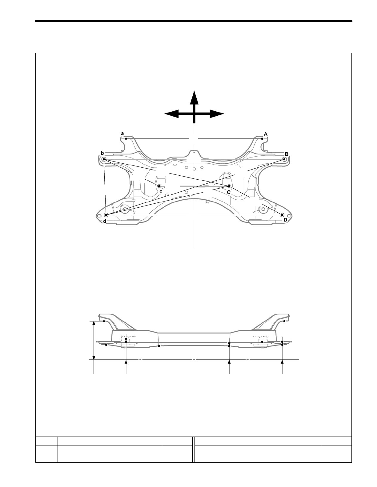
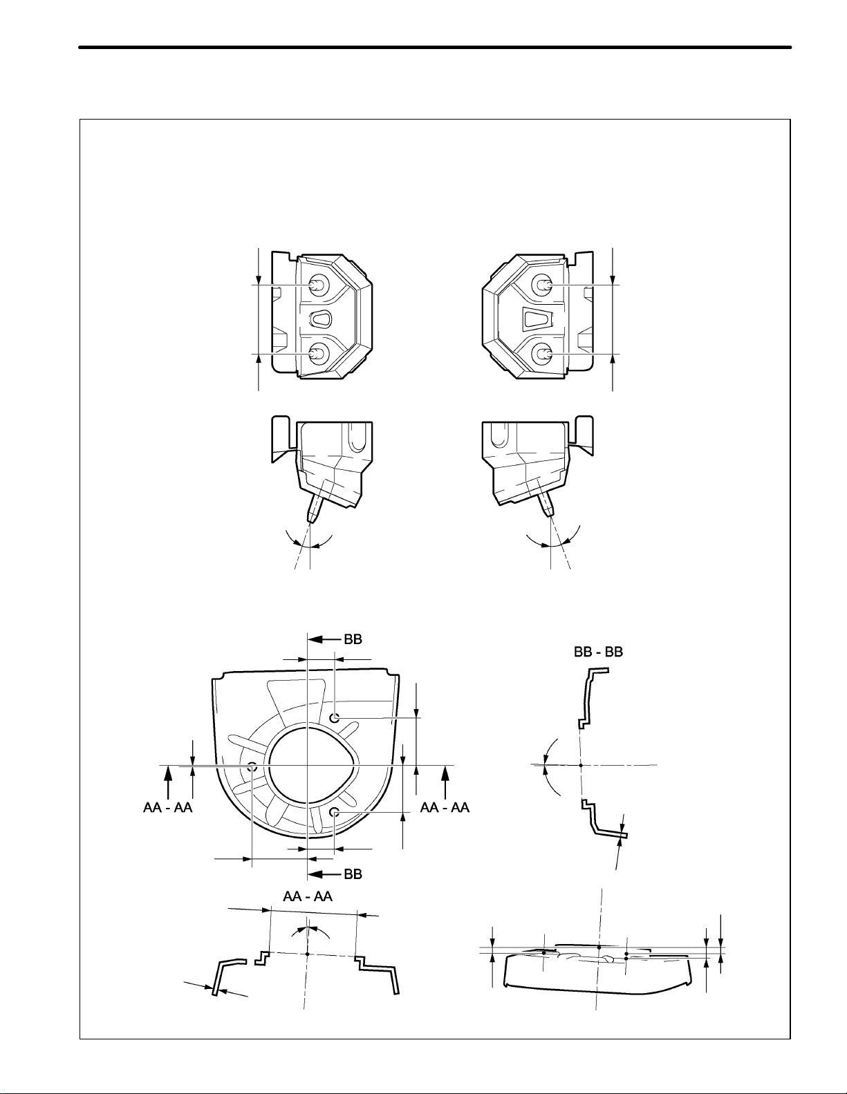
BODY DIMENSIONS DI-9
FRONT SUSPENSION CROSSMEMBER
(Three-Dimensional Distance)
Front
309
(12.17)
335
(13.19)
LH
660
(25.98)
354
(13.94)
689
(27.13)
912
(35.91)
890
(35.04)
639
(25.16)
RH
952
(37.48)
306
(12.05)
B,b
194
(7.64)
A,a
89
(3.50)
HINT: For symbols, capital letters indicate right side of vehicle,
small letters indicate left side of vehicle (seen from rear).
Symbol Name Hole dia.
A, a
Lower arm installation hole
B, b
Front suspension crossmember installation hole
ø15.5 (0.61)
ø22 (0.87)
Imaginary
Datum Line
C,c
67
(2.64)
Symbol Name Hole dia.
C, c
D, d
Front suspension crossmember standard hole
Front suspension crossmember installation hole
D,d
73
(2.87)
mm (in.)
ø13 (0.51)
ø20 (0.79)
Page 14
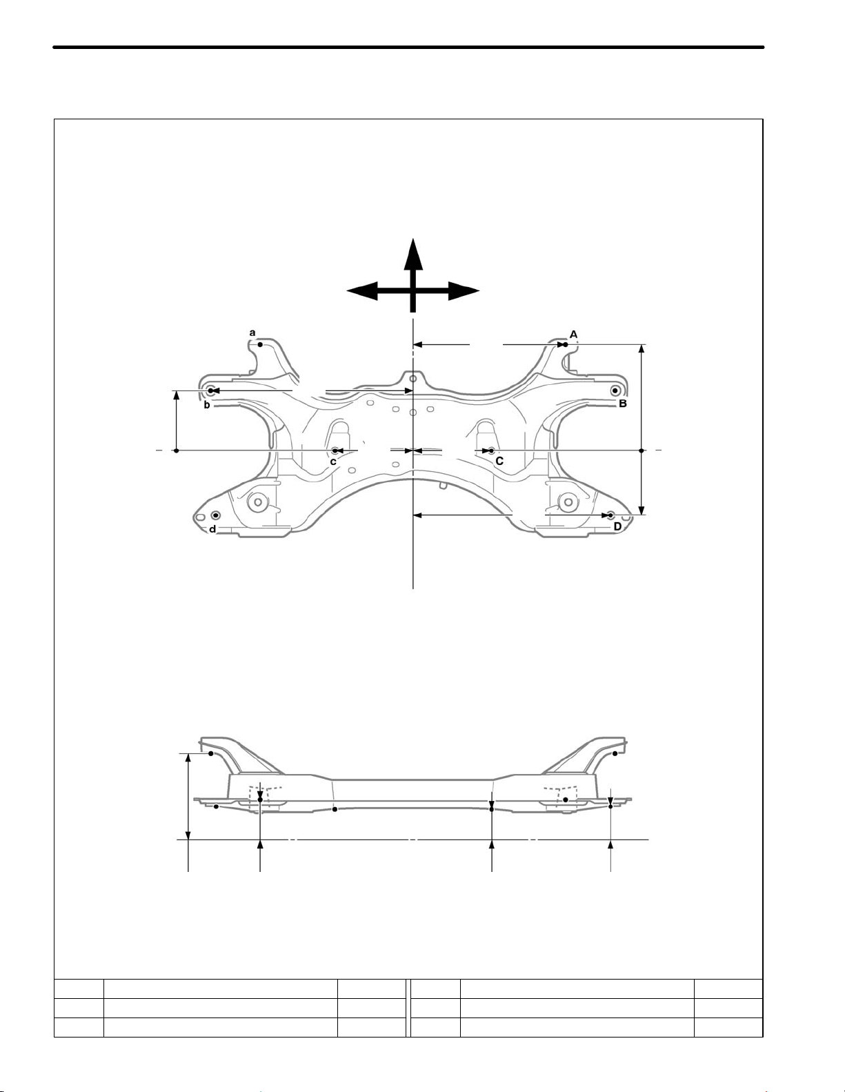
BODY DIMENSIONSDI-10
FRONT SUSPENSION CROSSMEMBER
(Two-Dimensional Distance)
Front
B,b
136
(5.35)
177
(6.97)
RH
344
(13.54)
445
(17.52)
0
A,a
242
(9.53)
D,d
148
(5.83)
LH
456
(17.95)
0
177
(6.97)
B,b
194
(7.64)
A,a
89
(3.50)
HINT: For symbols, capital letters indicate right side of vehicle,
small letters indicate left side of vehicle (seen from rear).
Symbol Name Hole dia.
A, a
B, b
Lower arm installation hole
Front suspension crossmember installation hole
ø15.5 (0.61)
ø22 (0.87)
Imaginary
Datum Line
C,c
67
(2.64)
Symbol Name Hole dia.
C, c
D, d
Lower arm installation hole
Front suspension crossmember installation hole
D,d
73
(2.87)
mm (in.)
ø13 (0.51)
ø20 (0.79)
Page 15
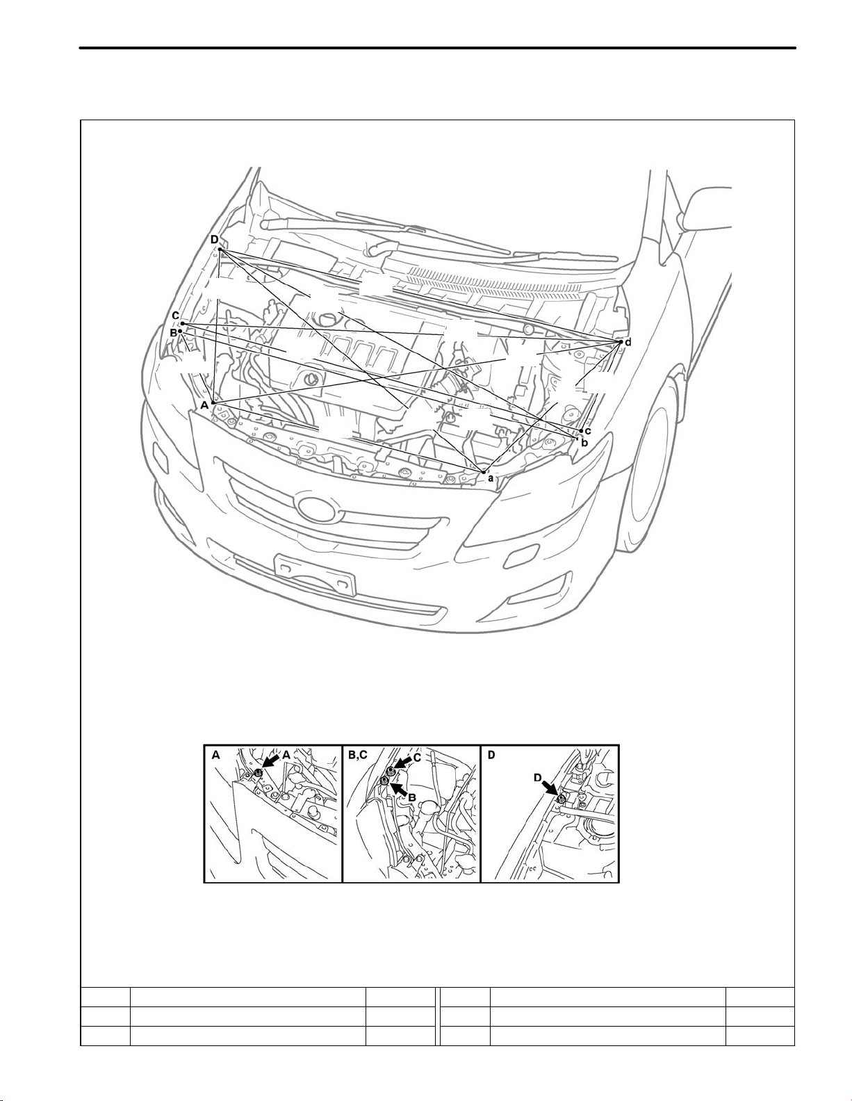
REFERENCE VALUE
ENGINE COMPARTMENT
(Three-Dimensional Distance)
BODY DIMENSIONS
DI-11
316
(12.44)
627
(24.68)
1,482
(58.35)
1,542
(60.71)
987
(38.86)
1,517
(59.72)
1,375
(54.13)
1,537
(60.51)
1,478
(58.19)
1,375
(54.13)
627
(24.68)
339
(13.35)
HINT:
1) For symbols, capital letters indicate right side of vehicle,
small letters indicate left side of vehicle (seen from rear).
2) These values are actual measurements made on model. Use these reference values.
Symbol Name Hole dia.
A, a
Front bumper cover installation bolt
B, b
Headlight installation bolt
Ċ
Ċ
Symbol Name Hole dia.
D, d
E, e
Front fender installation bolt
Front fender installation bolt
mm (in.)
Ċ
Ċ
Page 16
UNDER BODY
(Two-Dimensional Distance)
821
(32.32)
BODY DIMENSIONSDI-12
726
(28.58)
1,048
(41.26)
(55.20)
Vehicle Dimensions
A-B A-b A-C A-c A-D A-d
782 759 1,020 1,002 1,382 1,369
(30.79) (29.88) (40.16) (39.45) (54.41) (53.90)
1,402
912
(35.91)
890
(35.04)
966
(38.03)
870
(34.25)
978
(38.50)
1,352
(53.23)
HINT:
1) For symbols, capital letters indicate right side of vehicle,
small letters indicate left side of vehicle (seen from rear).
2) These values are actual measurements made on model. Use these reference values.
Symbol Name Hole dia.
A, a
B, b
Center member installation bolt
Front suspension crossmember installation bolt
–
–
Symbol Name Hole dia.
C, c
D, d
Front suspension crossmember installation bolt
Front side member installation hole
mm (in.)
–
ø18 (0.71)
Page 17
UNDER BODY
(Two-Dimensional Distance)
BODY DIMENSIONS DI-13
Front bumper reinforcement
59.8
[RH]
13.10_
Front suspension support
[LH]
59.8
12.3_
0.4
2.3
66.4
102
3_
32.6
32.3
56.7
57.5
6.6
2.3_
2.3
9.4
13.9
Unit: mm
Page 18

DI-14
MEMO
Page 19
INTRODUCTION
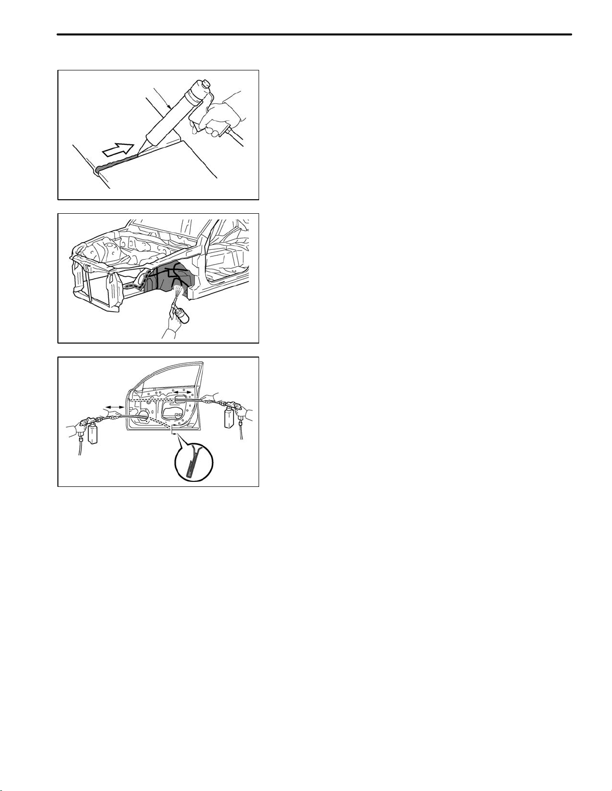
4. ANTI-RUST TREATMENT AFTER INSTALLATION
Sealer Gun
F33011
(a) BODY SEALER APPLICATION
PURPOSE:
For water-proofing and anti-rust measures, always
apply the body sealer to the body panel seams and
hems of the doors, hood, etc.
NOTICE:
Apply body sealer neatly to parts that require a
high quality appearance.
(b) UNDERCORT APPLICATION
PURPOSE:
To prevent corrosion and protect the body from gravel,
always apply a sufficient undercoating to the areas indicated.
IN-1
F33012
F33013
(c) VEHICLE BODY ANTI-RUST AGENT
APPLICATION
PURPOSE:
The purpose is to protect areas from rust which are difficult to paint such as the backside of the box-shaped
cross section frame parts.
METHOD:
Apply anti-rust agent through the service holes and/or
installation holes of the parts.
Page 20
INTRODUCTIONIN-2
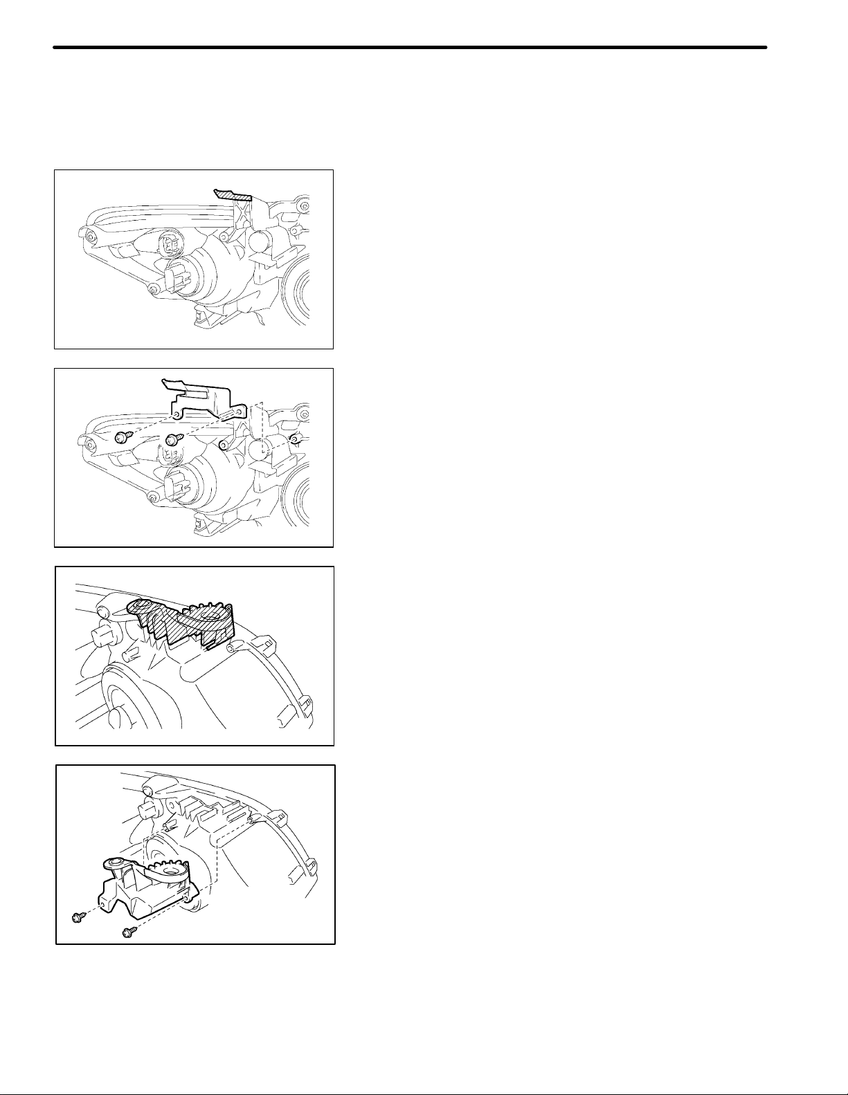
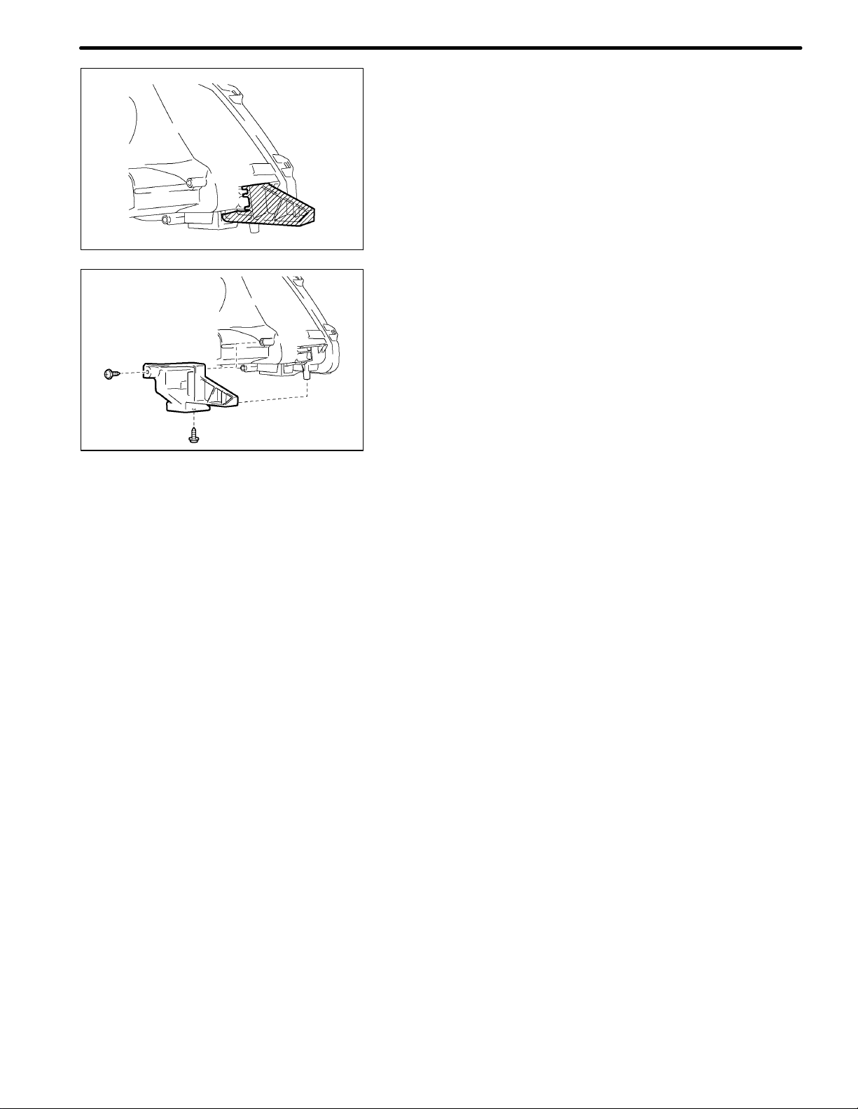
5. HEADLIGHT BRACKET REPAIR
HINT:
S If the installation area of the headlight assembly is damaged, use the supply retainer for low-cost
repair.
S Ensure that the headlight assembly is not damaged.
(a) INSTALL UPPER HEADLIGHT PROTECTOR
RETAINER
(1) Cut off the part shaded in the illustration and smooth
with sandpaper.
NOTICE:
After cutting off the part, place the upper headlight protector retainer against the bosses and
gradually file away the old bracket if it interferes
E163300
with the installation of the supply bracket.
(2) Install the upper headlight protector retainer with the
2 screws.
E163301
E160571
E160570
(b) INSTALL LOWER HEADLIGHT PROTECTOR
RETAINER
(1) Cut off the part shaded in the illustration and smooth
with sandpaper.
NOTICE:
After cutting off the part, place the lower headlight
protector retainer against the bosses and gradually file away the old bracket if it interferes with
the installation of the supply bracket.
(2) Install the lower headlight protector retainer with the 2
screws.
Page 21
E160573
E160572
INTRODUCTION IN-3
(c) INSTALL LOWER HEADLIGHT BRACKET
(1) Cut off the part shaded in the illustration and smooth
with sandpaper.
NOTICE:
After cutting off the part, place the lower headlight
bracket against the bosses and gradually file
away the old bracket if it interferes with the installation of the supply bracket.
(2) Install the lower headlight bracket with the 2 screws.
Page 22

INTRODUCTIONIN-4
6. PROCEDURES NECESSARY WHEN ECU OR OTHER PARTS
ARE REPLACED
(a) THE WORK LIST
(1) Each inspection procedure refers to the TOYOTA Repair Manual.
Effect/Inoperative
Replacement Part Necessary Procedure
Vehicle Identification
Number (VIN) registration
ECU commnication ID
ECM
S Automatic transmission
assembly (*1)
S Engine assembly (*1)
Tire pressure warning ECU
Tire pressure warning valve
and transmitter
Brake actuator assembly
(Skid control ECU)
S Yaw rate and
acceleration sensor
S Front wheel alignment
adjustment
S Power steering ECU (*2)
S Steering column (*2)
Power steering ECU (*3)
Steering column (*3)
registration
Reset memory (*1)
Reset memory
1. Register transmitter IDs
2. Initialize tire pressure
warning system
1. Register transmitter IDs
2. Initialize tire pressure
warning system
Perform yaw rate and
acceleration sensor zero
point calibration
1. Clear zero point
calibration data
2. Perform yaw rate and
acceleration sensor zero
point calibration
Perform rotation angle
sensor initialization and
torque sensor zero point
calibration.
1. Assist map writing
2. Torque sensor zero
point calibration
Torque sensor zero point
calibration
MIL comes on Using the Techstream.
S Wireless door lock control system
S Smart key system (*4)
S Engine start
S Large shift shock
S The deterioration of fuel efficien-
S Large shift shock
S The deterioration of fuel efficien-
S When DTC detection conditions
S Tire pressure monitoring function
1. When DTC detection conditions
2. Tire pressure monitoring function
S VSC OFF indicator light blinks
S VSC disabled or malfunctioning
S VSC OFF indicator light blinks
S VSC disabled or malfunctioning
S P / S warning light comes on
S EPS control
S P /S warning light comes on
S EPS control
Steering effort is different between
turning steering wheel to left and
right
Function When
Necessary Procedures
are not Performed
(*4)
cy
cy
of “transmitter ID not received”
DTC are met, TPWS indicator
blinks for 1 minute, and then
illuminates
of “transmitter ID not received”
DTC are met, TPWS indicator
blinks for 1 minute, and then
illuminates
of replaced wheel
Note
—
Using the Techstream.
Using the intelligent tester.
—
Even if only one wheel is
replaced, IDs for all 4
wheels must be registered.
Perform yaw rate and
acceleration sensor zero
point calibration with the
ignition switch on (engine
stopped).
Perform yaw rate and
acceleration sensor zero
point calibration with the
ignition switch on (engine
stopped).
DTC (C1515/C1525) will
be stored when the power
steering ECU is replaced.
DTC (C1515/C1525) will
be stored when the power
steering ECU is replaced.
—
Page 23

Replacement Part Necessary Procedure
1. Perform identification
S Door control transmitter
(*5)
S Door control receiver
(*5)
Steering lock actuator
(Steering lock ECU) (*4)
S Certification ECU (*4)
S Electrical key transmitter
(*4)
ID code box (*4)
Occupant classification
ECU
S Sliding roof drive gear
(Sliding roof ECU)
S Sliding roof housing
S Sliding roof drive cable
code registration (key
code)
2. Refer to wireless door
lock control system
“REGISTRATION”
procedures
ECU code registration Engine start —
Key ID registration
1. ECU code registration
2. ECU communication ID
registration
S Perform zero point
calibration
S Registration ECU data
Perform sliding roof drive
gear reset.
INTRODUCTION IN-5
Effect/Inoperative
Function When
Necessary Procedures
are not Performed
wireless door lock control system —
S Wireless door lock control system
S Smart key system
S Engine start
S Wireless door lock control system
S Smart key system
S Engine start
S Occupant classification system
S Passenger airbag ON / OFF
indicator
S Airbag system
(Front passenger side)
S Seat belt warning system
(Front passenger side)
S Automatic open/close function of
roof glass
S Jam protection function
S Operation function after ignition
switch off
Necessary when removed
and installed (Not
necessary when the sliding
roof drive gear (sliding roof
ECU) is removed and
installed together with the
sliding roof housing.)
Note
—
—
—
*1: for U341E, U250E Automatic Transaxle
*2: for 2AZ−FE
*3: for 2ZR−FE
*4: w/ Smart Key System
*5: w/o Smart Key System
Page 24

1. WORK PRECAUTIONS
Glass Cover
Seat Cover
F33000
WRONG
INTRODUCTION IN-5
PRECAUTION
(a) VEHICLE PROTECTION
(1) When welding, cover glass, seats, carpets, etc. with
heat resistant fireploof covers to protect them.
(b) SAFETY
(1) Never stand in the path of the chain when using a pull-
er on the body or frame, and be sure to attach a safety
cable.
WRONG
F33001
F33002
F33003
(2) If it is necessary to use a frame in the area of the fuel
tank, first remove the tank and plug the fuel line.
(c) SAFETY WORK CLOTHES
(1) In addition to the usual mechanic’s wear, cap and
safety shoes, the appropriate gloves, head protector,
welder’s glasses, ear plugs, face protector, dust
mask, etc. should be worn as the situation demands.
Code Name
A Dust mask
B Face protector
C Safety glasses
D Safety shoes
E Welder’s glasses
F Ear plugs
G Head protector
H Welder’s gloves
Page 25

INTRODUCTIONIN-6
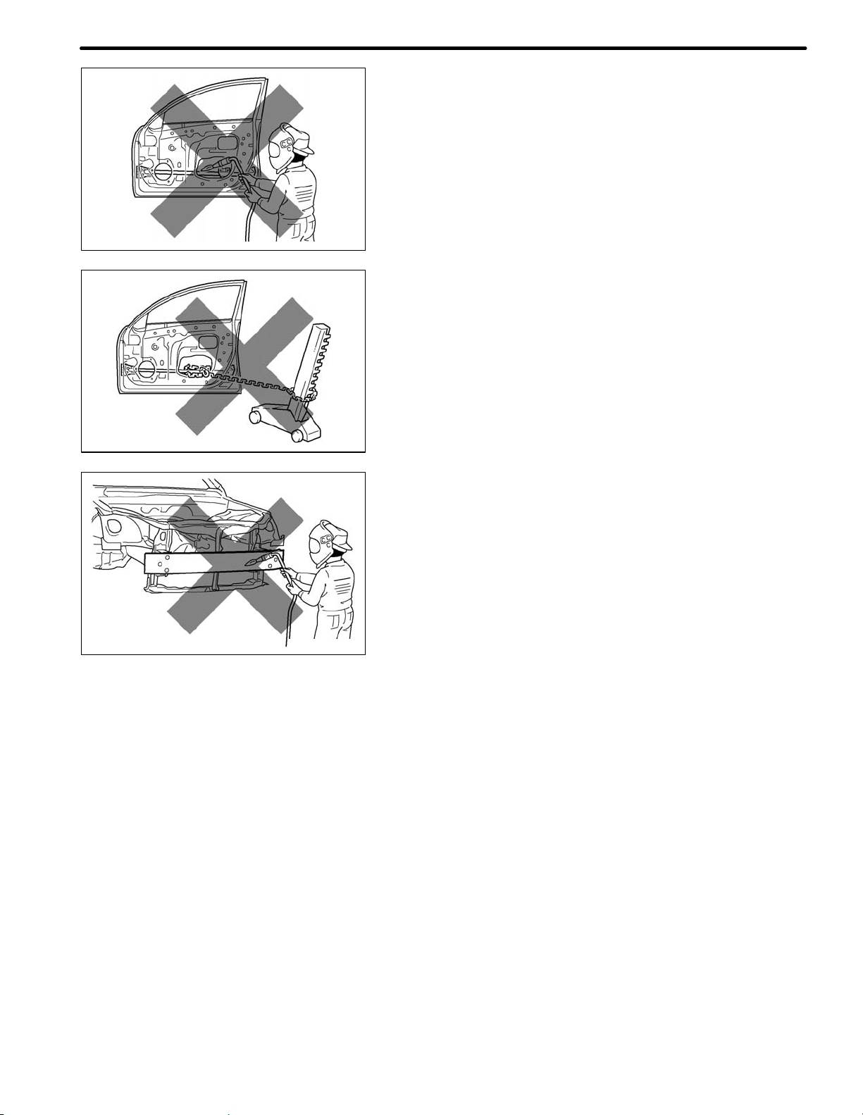
2. PRECAUTIONS WHEN REPAIRING BODY FRAME PARTS
(INCLUDING CRUSH BOX)
(a) PROHIBITION OF HEAT REPAIR FOR BODY
FRAME PARTS
(1) Rustproof high strength steel sheets are used for the
body frame. Therefore, if these parts are heat repaired using an acetylene torch or equivalent, the
crystalline structure changes, causing the strength of
the steel sheets to decrease. Also, the zinc corting
which is used to protect the body from rust will be
damaged. This causes the surface of the steel sheets
F33014
(b) WHEN TO REPLACE FRAME PARTS
F33015
to become oxidized, which reduces their ability to resist rust.
NOTICE:
Replace frame parts that have kinks.
HINT:
What is kink?
A deformatision bon a steel sheet that cannot be returned
to its original shape by pulling or hammering due to the deformation angle being sharp.
Page 26
F33016
F33017
INTRODUCTION IN-7
(c) REPAIR OF DOOR SIDE IMPACT BEAM IS
PROHIBITED
(1) The impact beam is desined so that it performs at
100% in its original shape.
However, if the impact beam is repaired, its performance may not be the same as before the accident.
PARTS EHICH ARE PROHIBITED TO BE
REPAIRED: Door side impact beam
F30442
(d) REPAIR OF BUMPER REINFORCEMENT IS
PROHIBITED
(1) The bumper reinforcement is designed so that it par-
forms at 100% in uts original shape.
However, if the impact beam is repaired, its performance may not be the same as before the accident.
PARTS EHICH ARE PROHIBITED TO BE
REPAIRED: Bumper reinforcement
Page 27

IN-8
INTRODUCTION
3. PRECAUTIONS FOR CORRECT REPAIR
(a) REMOVAL OF ADJACENT COMPONENTS
(1) When removing adjacent components, apply protec-
tive tape to the surrounding body and your tools to
prevent damage.
NOTICE:
If the paint film is damaged, make sure to refinish
the paint.
F33007
(b) ANTI-RUST TREATMENT BEFORE WELDING
(1) Apply welding primer to the contact surfaces of the
welding areas to protect them from rust.
NOTICE:
Do not apply welding primer outside of the contact surfaces.
Puncher
Old Spot Locations
New Spot Locations
F33008
F33009
F33010
(c) MAKING HOLES FOR PLUG WELDING
(1) For areas where a spot welder cannot be used, use a
puncher or drill to make holes for plug welding.
Thickness of welded portion Diameter of plug hole
Under 10 mm (0.04 in.) Over 5 mm (0.20 in.)
1.0 to 1.6 mm (0.04 to 0.06 in.) Over 6.5 mm (0.26 in.)
1.7 to 2.3 mm (0.07 to 0.09 in.) Over 8 mm (0.31 in.)
Over 2.4 mm (0.09 in.) Over 10 mm (0.39 in.)
(d) WELDING PRECAUTIONS
(1) The number of welding spots should be as follows.
Spot weld: 1.3 X No. of manufacturer’s spots
Plug weld: More than No. of manufacturer’s plugs
(2) Spot weld locations
Avoid welding over previously welded areas.
Page 28

INTRODUCTION
8. PRECAUTIONS FOR RESIN PARTS
(a) PLASTIC PROPERTIES CHART
(1) When repairing, some parts may be deformed by the heat. Therefore, confirm the properties of
the platic parts, and remove parts beforehand as necessary.
Heat*
Code Material name
resistant
temperature
limit _C (_F)
alcohol or gasoline
Resistance to
IN-9
Notes
Acrylonitrile
ABS
AES
ASA
EPDM
PA
PBT
PC Polycarbonate
Butadiene
Styrene
Acrylonitrile
Ethylene Styrene
Acrylonitrile
Styrene
Acrylate
Ethylene
Propylene
Polyamide
(Nylon)
Polybutylene
Terephthalate
80
(176)
80
(176)
80
(176)
100
(212)
80
(176)
160
(320)
120
(248)
Alcohol is harmless if applied only
for short time in small amounts
(e.g., quick wiping to remove
grease).
Alcohol is harmless if applied only
for short time in small amounts
(e.g., quick wiping to remove
grease).
Alcohol is harmless if applied only
for short time in small amounts
(e.g., quick wiping to remove
grease).
Alcohol is harmless. Gasoline is
harmless if applied only for short
time in small amounts.
Alcohol and gasoline are harmless. Avoid battery acid.
Alcohol and gasoline are harmless. Most solvents are harmless.
Alcohol is harmless.
Avoid gasoline and organic
or aromatic solvents.
Avoid gasoline and organic
or aromatic solvents.
Avoid gasoline and organic
or aromatic solvents.
Most solvents are harmless
but avoid dipping in
gasoline,solvents, etc.
Avoid gasoline brake fluid,
wax, wax removers and
organic solvents.
Avoid alkali.
PE Polyethylene
PET
PMMA
PP Polypropylene
PVC
TPE
TPO
Polyethylene
Terephthalate
Polymethyl
Methacrylate
Polyvinylchloride
(Vinyl)
Thermoplastic
Elastomer
Thermoplastic
Olefine
80
(176)
75
(167)
80
(176)
80
(176)
80
(176)
80
(176)
80
(176)
Alcohol and gasoline are harmless. Most solvents are harmless.
Alcohol and gasoline are harmless. Avoid dipping in water.
Alcohol is harmless if applied only
for short time in small amounts
Alcohol and gasoline are harmless. Most solvents are harmless.
Alcohol and Gasoline are harmless.
if applied only for short time in small
amounts. (e.g., quick wiping to
remove grease).
Alcohol and Gasoline are harmless.
if applied only for short time in small
amounts. (e.g., quick wiping to
remove grease).
Alcohol and Gasoline are harmless.
if applied only for short time in small
amounts. (e.g., quick wiping to
remove grease).
Avoid dipping or immersing
in alcohol, gasoline,
solvents, etc.
Avoid dipping or immersing
in alcohol, gasoline,
solvents, etc.
Most solvents are harmless
but avoid dipping in
gasoline, solvents, etc.
Most solvents are harmless
but avoid dipping in
gasoline, solvents,
etc.TSOP
Page 29

IN-10
Code Material name
INTRODUCTION
Heat*
resistant
temperature
limit _C (_F)
Resistance to
alcohol or gasoline
Notes
TSOP
TOYOTA
Super Olefine
Polymer
80
(176)
Alcohol and gasoline are harmless. Most solvents are harmless.
* Temperatures higher than those listed here may result in material deformation during repair.
Page 30

Headlight
(PC/PP)
INTRODUCTION
Cowl Top Ventilator Louver
(PE/PP/TSOP)
Front Wiper Blade
(PBT/PE)
IN-11
Front Piller Cover
(AES)
Antenna
(ABSSASA / PC)
Emblem
(AES/ABS)
Radiator Grille
(TSOP)
Front Bumper Cover
(TSOP)
Front Spoiler Cover
(PP)
Door Outside Handle
(PC/PBT)
Body Rocker Panel Moulding
(TSOPSPP)
Outer Rear View Mirror
(ASA/PBT/ABSSPA/ PE / PET / PBT)
Foglight
(ASA/PBT)
/ Made up of 2 or more kinds of materials.
S Resin material differs with model.
B0709140118B
Page 31
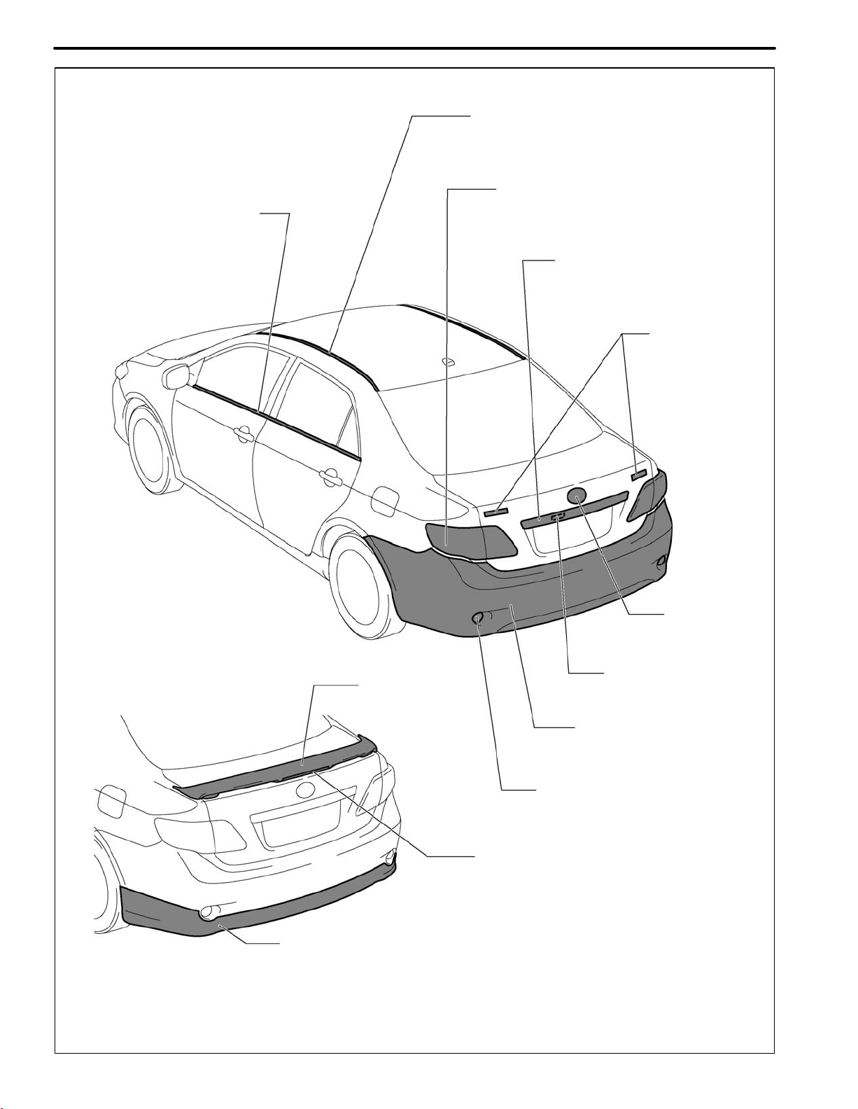
IN-12
Door Belt Moulding
(EPDM/PP)
INTRODUCTION
Roof Drip Side Finish Moulding
(TPE)
Rear Combination Light
(ASA/PMMA)
Luggage Compartment
Door Outside Garnish
(ABS)
Emblem
(ABS)
Rear Spoiler
(ABS)
Rear Under Spoiler
(TSOP)
Emblem
(ABS)
Licence Plate Light
(PA/ PC)
Rear Bumper Cover
(TSOP)
Reflex Refrector
(ABS/PMMA)
High Mount Stop Light
(ABS/PMMA)
/ Made up of 2 or more kinds of materials.
S Resin material differs with model.
B0709140120
Page 32

ABOUT THIS VEHICLE
1. STRUCTURAL OUTLINE
INTRODUCTION
IN-13
Adhesive Application Area
Laser Welding
. . .
Formed material application areas (refer to PC-8)
B0706260033
Page 33

IN-14
INTRODUCTION
. . .
980 MPa Ultra High stregth steel
. . .
590 MPa High stregth steel
. . .
440 MPa High stregth steel
. . .
370 MPa High stregth steel
. . .
340 MPa High stregth steel
B0710190003
Page 34
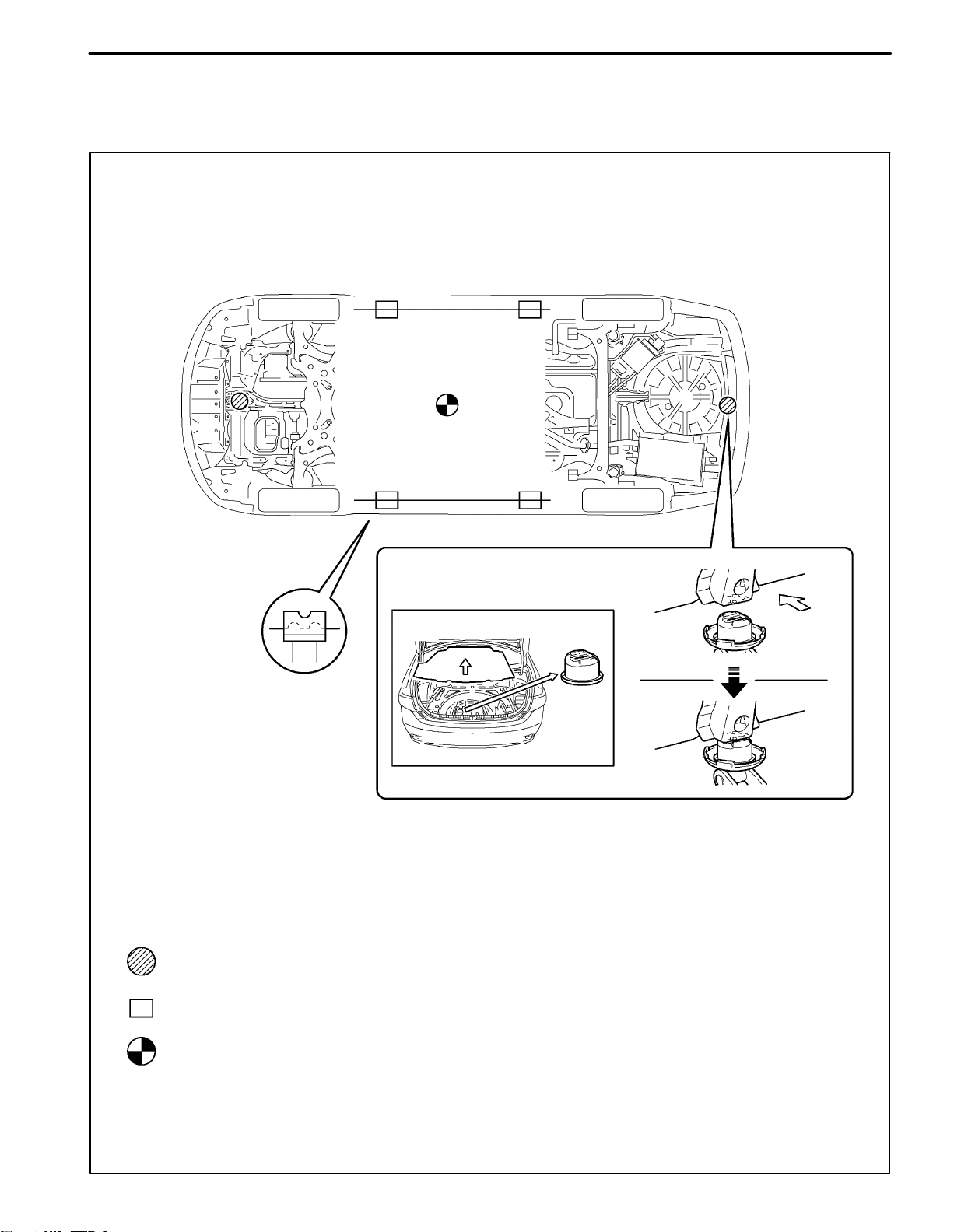
INTRODUCTION
2. NOTICE ABOUT VEHICLE CONDITION WHEN JACKING UP
VEHICLE
(a) NOTICE FOR USING JACK AND SAFETY STAND
IN-15
Remove the jack attachment from the the spare tire cover in the
trunk, then, align the concave portion with the rear jack position and
jack up the vehicle.
NOTICE: Set the jack attachment with the arrow facing towards the
front of the vehicle.
: JACK POSITION
: SUPPORT POSITION, PANTOGRAPH JACK POSITION
: VEHICLE CENTER OF GRVITY (unloaded condition)
Front of
vehicle
B0709140118A
Page 35

IN-16
INTRODUCTION
(b) NOTICE FOR USING SWING ARM TYPE LIFT
Center of Lift
Rubber Attachment
: VEHICLE CENTER OF GRAVITY (unloaded condition)
B0701260007
Page 36

INTRODUCTION
(c) NOTICE FOR USING PLATE TYPE LIFT
IN-17
Attachment Dimensions
85 mm (3.35 in.)
100 mm
(3.94 in.)
Right and left set position
Front and rear set position
200 mm (7.87 in.)
Attachment
70 mm (2.76 in.)
S Place the vehicle over the center of the lift.
S Align the cushion ends of the plate with the
attachment lower ends (A and C).
S Align the attachment upper end (B) with the
rocker flange front side notch.
B0701260008
Page 37

IN-18
3. DAMAGE DIAGNOSIS
INTRODUCTION
Confirmation Point
Head-on Collision:
Front Bumper
Reinforcement
Side Collision:
Collision Direction
Front Body Pillar
Upper Reinforcement
Front Side Member
Collision Force Absorption Direction
Rocker Panel Reinforcement
Roof Reinforcement
Floor Cross Member
Center Pillar Reinforcement
B0706260035
Page 38

4. COMPONENTS
(a) Front bumper
FRONT BUMPER
SIDE SUPPORT RH
INTRODUCTION
IN-19
FRONT BUMPER
ENERGY ABSORBER
36 (367,27)
FRONT BUMPER REINFORCEMENT
SUB-ASSEMBLY
FRONT BUMPER
RADIATOR GRILLE
PROTECTOR
SIDE SUPPORT LH
FRONT BUMPER ASSEMBLY
CAUTION:
The bolts must be tightened to the torque specification, as they are related to vehicle safety during a collision.
N.m (kgf.cm, ft..lbf)
: Specified torque
B0710120001B
Page 39

IN-20
(b) Side Mudguard
INTRODUCTION
for Sport Package:
NO. 1 MOULDING TAPE
Non-reusable part
SIDE MUDGUARD
ROCKER PANEL REAR
MOULDING RETAINER
ROCKER PANEL FRONT
MOULDING RETAINER
NO. 2 MOULDING TAPE
SIDE MUDGUARD
B192955E01
Page 40

(c) Rear bumper
REAR BUMPER SIDE
SUPPORT LH
REAR BUMPER ARM
LH
36 (367, 27)
INTRODUCTION
REAR BUMPER SIDE
SUPPORT RH
REAR BUMPER ARM
RH
36 (367, 27)
IN-21
NO. 2 REAR BUMPER
SIDE SUPPORT RH
REAR UPPER BUMPER
RETAINER RH
NO. 1 REAR BUMPER
REINFORCEMENT
NO. 2 REAR BUMPER
SIDE SUPPORT LH
REAR UPPER BUMPER
RETAINER LH
w/ Rear Fender Mudguard:
36 (367, 27)
REAR BUMPER
ASSMBLY
REAR QUARTER
PANEL MUDGUARD LH
REAR BUMPER
ENERGY ABSORBER
REAR QUARTER
PANEL MUDGUARD RH
CAUTION:
The bolts must be tightened to the torque specification, as they are related to vehicle safety during a collision.
N.m (kgf.cm, ft..lbf)
: Specified torque
B0710120002
Page 41

IN-22
(d) Door
FRONT DOOR INNER
GLASS WEATHERSTRIP
INTRODUCTION
FRONT DOOR INSIDE
HANDLE BEZEL
FRONT DOOR TRIM
BOARD SUB-ASSEMBLY
FRONT DOOR INSIDE
HANDLE SUB-ASSEMBLY
w/o Power Window:
FRONT ARMREST UPPER
BASE PANEL
FRONT DOOR REGULATOR
INSIDE HANDLE PLATE
SNAP RING
FRONT DOOR WINDOW
REGULATOR HANDLE ASSEMBLY
w/ Power Window:
FRONT ARMREST
UPPER BASE PANEL
B0707100004A
Page 42

REAR DOOR INNER
GLASS WEATHERSTRIP
INTRODUCTION
IN-23
REAR DOOR INSIDE
HANDLE BEZEL
w/o Power Window:
REAR DOOR ARMREST
UPPER BASE PANEL
PLATE
REAR DOOR INSIDE
HANDLE SUB-ASSEMBLY
REAR DOOR TRIM
BOARD SUB-ASSEMBLY
w/ Power Window:
REAR DOOR ARMREST
UPPER BASE PANEL
SNAP RING
REAR DOOR WINDOW
REGULATOR HANDLE
ASSEMBLY
B0707100005A
Page 43

IN-24
INTRODUCTION
w/ Rear Spoiler:
REAR SPOILER
ASSEMBLY
LIGGAGE COMPARTMENT
DOOR COVER
B0707100006
Page 44
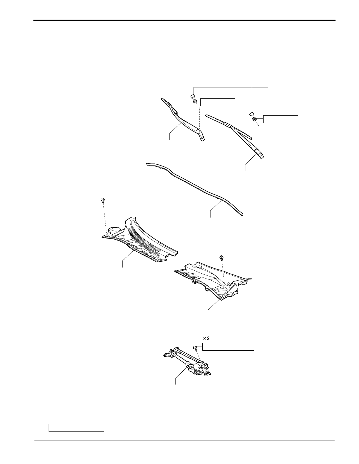
(e) Cowl Top Ventilator Louver
FRONT WIPER ARM AND
BLADE ASEMBLY RH
INTRODUCTION
IN-25
FRONT WIPER ARM
HEAD CAP
26 (265, 19)
26 (265, 19)
FRONT WIPER ARM AND
BLADE ASEMBLY LH
CENTER NO. 1 COWL TOP VENTILATOR LOUVER
COWL TOP VENTILATOR LOUVER LH
WINDSHIELD WIPER MOTOR AND LINK ASSEMBLY
HOOD TO COWL TOP SEAL
5.5 (56, 49 in.*lbf)
CAUTION:
The bolts must be tightened to the torque specification, as they are related to vehicle safety during a collision.
N.m (kgf.cm, ft..lbf)
: Specified torque
B0707100007
Page 45
IN-26
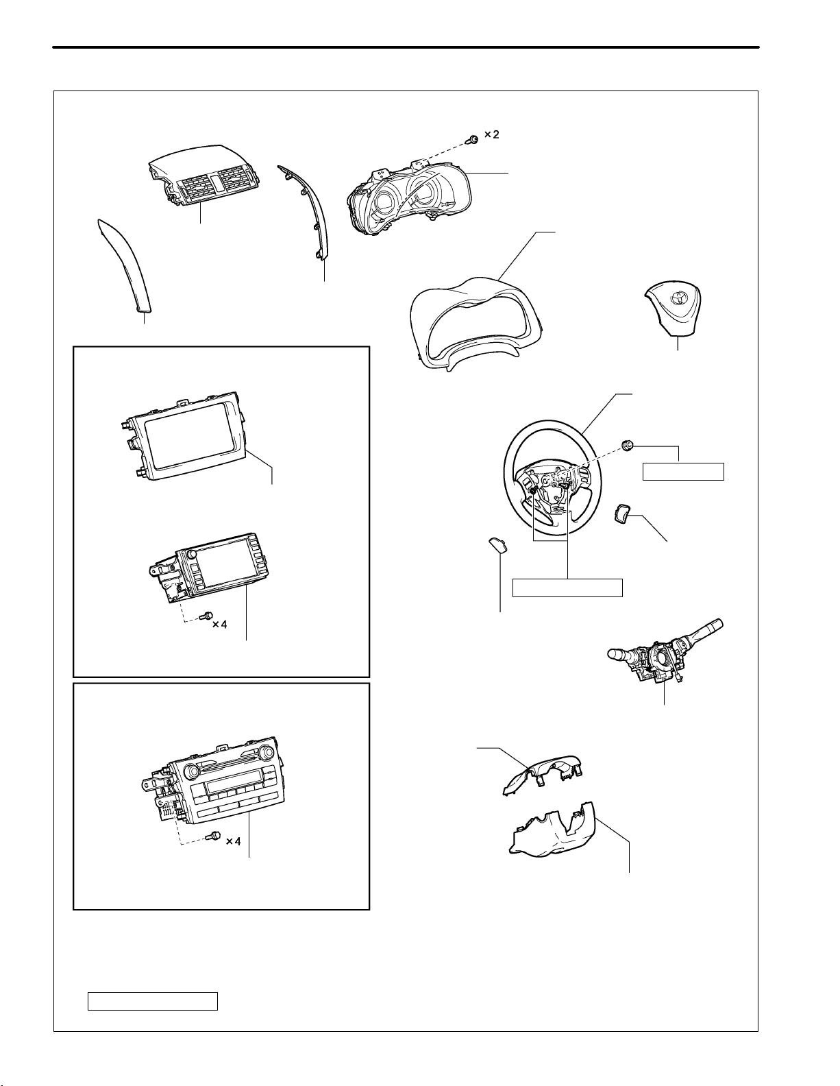
(f) Instrument panel
INTRODUCTION
COMBINATION METER ASSEMBLY
CENTER INSTRUMENT PANEL
REGISTER ASSEMBLY
INSTRUMENT PANEL FINISH
PANEL END RH
INSTRUMENT PANEL FINISH PANEL END LH
w/ Navigation System:
CENTER INSTRUMENT CLUSTER
FINISH PANEL SUB-ASSEMBLY
INSTRUMENT CLUSTER
FINISH PANEL ASSEMBLY
STEERING PAD
STEERING WHEEL
ASSEMBLY
50 (510, 37)
LOWER NO.2 STEERING
WHEEL COVER
8.8 (90, 78 in..ibf)
LOWER NO.3 STEERING WHEEL COVER
NAVIGATION RECEIVER WITH BRACKET
w/o Navigation System:
TURN SIGNAL SWITCH ASSEMBLY WITH
SPIRAL CABLE SUB-ASSEMBLY
UPPER STEERING
COLUMN COVER
RADIO RECEIVER WITH BRACKET
CAUTION:
The bolts must be tightened to the torque specification, as they are related to vehicle safety during a collision.
N.m (kgf.cm, ft..lbf)
: Specified torque
LOWER STEERING COLUMN COVER
B0710150022
Page 46

INTRODUCTION
w/ Curtain Shield Airbag:
IN-27
w/ Curtain Shield Airbag:
SIDE INSTRUMENT
PANEL LH
FRONT PILLAR
GARNISH CLIP
FRONT PILLAR
GARNISH CLIP
FRONT PILLAR GARNISH RH
FRONT PILLAR GARNISH LH
SIDE INSTRUMENT
PANEL RH
20 (204, 15)
UPPER INSTRUMENT
PANEL SUB-ASSEMBLY
NO. 2 INSTRUMENT PANEL
NO. 1 INSTRUMENT PANEL
REGISTER ASSEMBLY
REGISTER ASSEMBLY
LOWER INSTRUMENT PANEL
FINISH PANEL LH
LOWER INSTRUMENT PANEL
NO. 1 INSTRUMENT PANEL
BOX DOOR SUB-ASSEMBLY
FINISH PANEL RH
LOWER INSTRUMENT PANEL FINISH PANEL ASSEMBLY
GLOVE COMPARTMENT
DOOR ASSEMBLY
CAUTION:
The bolts must be tightened to the torque specification, as they are related to vehicle safety during a collision.
N.m (kgf.cm, ft..lbf)
: Specified torque
Non-reusable part
B0710150023
Page 47

IN-28
INTRODUCTION
INSTRUMENT PANEL
BOX ASSEMBLY
FRONT NO. 2 CONSOLE
BOX INSERT
for Automatic Transaxle:
SHIFT LEVER KNOB
SUB-ASSEMBLY
CENTER NO. 1 INSTRUMENT
CLUSTER FINISH PANEL
ASSEMBLY
for Manual Transaxle:
SHIFT LEVER KNOB
SUB-ASSEMBLY
CENTER NO. 1 INSTRUMENT
CLUSTER FINISH PANEL ASSEMBLY
FRONT NO. 1 CONSOLE BOX INSERT
for Automatic Transaxle:
CONSOLE BOX ASSEMBLY
CONSOLE BOX
CARPET
for Manual Transaxle:
CONSOLE BOX ASSEMBLY
UPPER CONSOLE PANEL
SUB-ASSEMBLY
B0710150026
Page 48

LOWER INSTRUMENT PANEL
SUB-ASSEMBLY
COWL SIDE TRIM
BOARD LH
FRONT DOOR
SCUFF PLATE LH
w/ Smart Key System:
INTRODUCTION
IN-29
COWL SIDE TRIM
BOARD RH
FRONT DOOR
SCUFF PLATE RH
NO. 1 SWITCH HOLE BASE
w/o Smart Key System:
NO. 1 SWITCH HOLE BASE
for Manual Air Conditioning System:
AIR CONDITIONING
CONTROL ASSEMBLY
LOWER INSTRUMENT PANEL
FINISH PANEL SUB-ASSEMBLY
w/ Instrument Panel Under Cover:
NO. 2 INSTRUMENT PANEL
UNDER COVER SUB-ASSEMBLY
NO. 1 INSTRUMENT PANEL
UNDER COVER SUB-ASSEMBLY
for Automatic Air Conditioning System:
INSTRUMENT PANEL
HOLE COVER
AIR CONDITIONING
PANEL ASSEMBLY
CAUTION:
The bolts must be tightened to the torque specification, as they are related to vehicle safety during a collision.
N.m (kgf.cm, ft..lbf)
: Specified torque
B0710150027
Page 49
IN-30
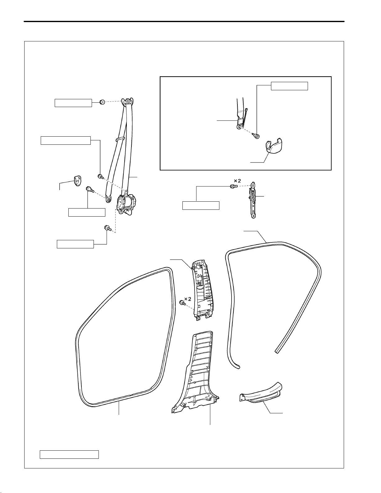
(g) Interior trim
INTRODUCTION
41 (420, 30)
5.0 (51, 44 in..ibf)
LAP BELT OUTER
ANCHOR COVER
41 (420, 30)
41 (420, 30)
UPPER CENTER PILLAR GARNISH
for Front Passenger Side:
FRONT SEAT
OUTER BELT
ASSEMBLY RH
FRONT SEAT OUTER
BELT ASSEMBLY
41 (420, 30)
REAR DOOR OPENING
TRIM WEATHERSTRIP
41 (420, 30)
FRONT SEAT BELT
ANCHOR BASE
LAP BELT OUTER
ANCHOR COVER
FRONT SHOULDER
BELT ANCHOR
ADJUSTER ASSEMBLY
REAR DOOR
FRONT DOOR OPENING
TRIM WEATHERSTRIP
CAUTION:
The bolts must be tightened to the torque specification, as they are related to vehicle safety during a collision.
N.m (kgf.cm, ft..lbf)
: Specified torque
LOWER CENTER
PILLAR GARNISH
SCUFF PLATE
B0710120003
Page 50
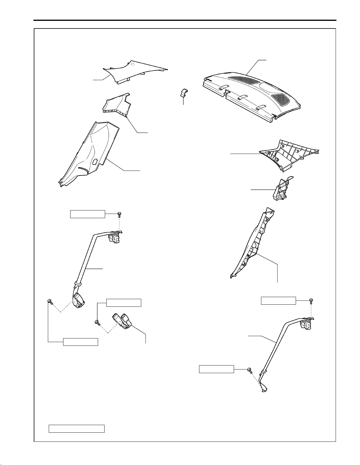
ROOF SIDE INNER
GARNISH ASSEMBLY RH
INTRODUCTION
PACKAGE TRAY TRIM
BELT HOLE COVER
ROOF SIDE INNER
GARNISH BOARD RH
ROOF SIDE INNER
GARNISH ASSEMBLY LH
REAR SEAT SIDE GARNISH RH
IN-31
PACKAGE TRAY TRIM
PANEL ASSEMBLY
41 (420, 30)
41 (420, 30)
REAR SEAT INNER WITH
CENTER BELT ASEMBLY RH
41 (420, 30)
REAR SEAT OUTER BELT ASSEMBLY
REAR SEAT INNER WITH
CENTER BELT ASEMBLY LH
ROOF SIDE INNER
GARNISH BOARD LH
REAR SEAT SIDE GARNISH LH
41 (420, 30)
41 (420, 30)
CAUTION:
The bolts must be tightened to the torque specification, as they are related to vehicle safety during a collision.
N.m (kgf.cm, ft..lbf)
: Specified torque
B0710120006
Page 51

IN-32
INTRODUCTION
(h) Seat
for Manual Seat:
FRONT SEAT HEADREST
ASSEMBLY
INNER SEAT
TRACK COVER
OUTER SEAT TRACK
COVER
FRONT SEAT ASSEMBLY
for Power Seat:
FRONT SEAT HEADREST ASSEMBLY
37 (377, 27)
37 (377, 27)
INNER SEAT
TRACK COVER
OUTER SEAT TRACK
COVER
FRONT SEAT ASSEMBLY
CAUTION:
The bolts must be tightened to the torque specification, as they are related to vehicle safety during a collision.
N.m (kgf.cm, ft..lbf)
: Specified torque
B0707100014A
Page 52

INTRODUCTION
IN-33
REAR SEAT HEADREST
ASSEMBLY RH
REAR SEAT CENTER HEADREST
ASSEMBLY
REAR SEATBACK
ASSEMBLY RH
REAR SEAT HEADREST
ASSEMBLY LH
18 (184, 13)
REAR SEATBACK
ASSEMBLY LH
18 (184, 13)
REAR SEAT CUSHION
ASSEMBLY
CAUTION:
The bolts must be tightened to the torque specification, as they are related to vehicle safety during a collision.
N.m (kgf.cm, ft..lbf)
: Specified torque
B0710120007
Page 53
IN-34
INTRODUCTION
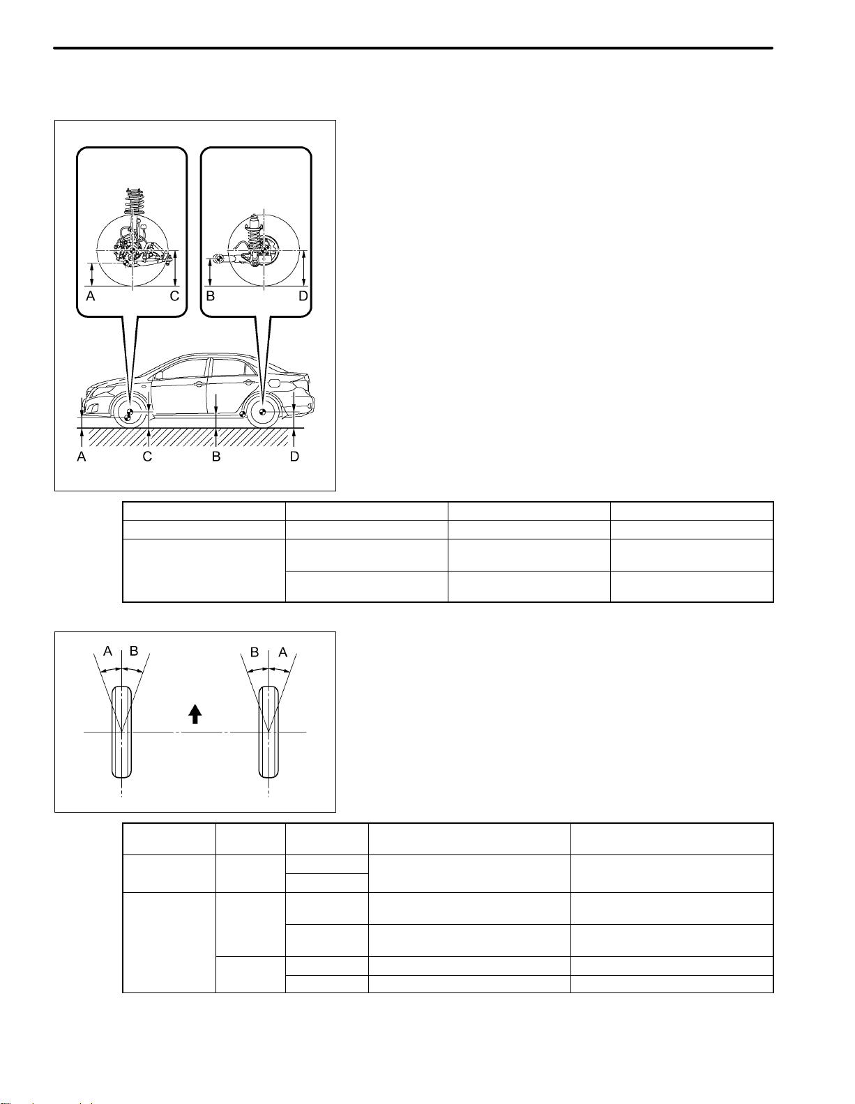
5. WHEEL ALIGNMENT STANDARD
(a) FRONT WHEEL ALIGNMENT
(1) Vehicle Height (Unloaded Vehicle)
NOTICE:
S Before inspecting the wheel alignment, adjust
S Be sure to perform measurement on a level
S If it is necessary to go under the vehicle for
Measuring points:
A: No. 1 lower suspension arm bushing set bolt
B: Rear axle beam set bolt ground clearance
C: Front wheel center ground clearance
D: Rear wheel center ground clearance
the vehicle height to the specified value.
surface.
measurement, confirm that the parking brake
is applied and the vehicle is secured with
chocks.
ground clearance
C178672E02
– Engine Front C – A Rear D – B
for TMC Made 2ZR-FE 92 mm (3.62 in.) 45 mm (1.77 in.)
except TMC Made
2ZR-FE
2AZ-FE
92 mm (3.62 in.)
80 mm (3.15 in.)*
96 mm (3.78 in.)
81 mm (3.19 in.)*
45 mm (1.77 in.)
32 mm (1.26 in.)*
51 mm (2.01 in.)
36 mm (1.42 in.)*
*for vehicle height for Mexico, add 15 mm (0.591 in.)
(2) Wheel Angle (Unloaded Vehicle)
Front
A: Inside
B: Outside
C132439E01
– Engine Tire Size Inside Wheel
for TMC Made 2ZR-FE
except TMC
Made
2ZR-FE
2AZ-FE
195/65R15
205/55R16
195/65R15
205/55R16
205/55R16* 37_19’ +/-2_ (37.32_ +/-2_)* 32_18’ (32.30_)*
215/45R17 36_59’ +/-2_ (36.98_ +/-2_) 32_01’ (32.02_)
38_13’ +/-2_ (38.22_ +/-2_) 32_50’ (32.83_)
38_13’ +/-2_ (38.22_ +/-2_)
38_29’ +/-2_ (38.48_ +/-2_)*
38_13’ +/-2_ (38.22_ +/-2_)
38_31’ +/-2_ (38.52_ +/-2_)*
Outside Wheel
Reference
32_50’ (32.83_)
33_04’ (33.07_)*
32_50’ (32.83_)
33_04’ (33.07_)*
*for vehicle height for Mexico, add 15 mm (0.591 in.)
If the angles are not as specified, check and adjust the
right and left rack end lengths.
Page 54

INTRODUCTION
(3) Camber (Unloaded Vehicle)
IN-35
Alignment
Tester
Gauge
C132440E07
– Engine Tire Size Camber Inclination Right-Left Difference
for TMC Made 2ZR-FE
2ZR-FE
except TMC
Made
2AZ-FE
195/65R15
205/55R16
195/65R15
205/55R16
205/55R16* -0_27’ (-0.62_)*
215/45R17 -0_37’ (-0.62_)
-0_35’ (-0.58_)
-0_34’ (-0.57_)
-0_26’ (-0.43_)*
-0_35’ (-0.58_)
-0_26’ (-0.43_)*
45’ (0.75_) or less
* for vehicle height for Mexico, add 15 mm (0.591 in.)
(4) Caster (Unloaded Vehicle)
– Engine Tire Size Camber Inclination Right-Left Difference
for TMC Made 2ZR-FE
2ZR-FE
except TMC
Made
2AZ-FE
195/65R15 2_50’ +/-45’ (2.83_ +/-0.75_)
205/55R16 2_51’ +/-45’ (2.85_ +/-0.75_)
195/65R15
205/55R16
205/55R16* 2_45’ +/-45’ (2.75_ +/-0.75_)*
215/45R17 2_55’ +/-45’ (2.92_ +/-0.75_)
2_50’ +/-45’ (2.83_ +/-0.75_)
2_40’ +/-45’ (2.67_ +/-0.75_)*
2_50’ +/-45’ (2.83_ +/-0.75_)
2_41’ +/-45’ (2.68_ +/-0.75_)*
45’ (0.75_) or less
* for vehicle height for Mexico, add 15 mm (0.591 in.)
(5) Steering Axis Inclination (Unloaded Vehicle)
except TMC Made:
– Engine Tire Size Steering Axis Inclination
for TMC Made 2ZR-FE
2ZR-FE
except TMC
Made
2AZ-FE
195/65R15
205/55R16
195/65R15
205/55R16
205/55R16* 12_16’ (12.27_)*
215/45R17 12_37’ (12.62_)
12_32’ (12.53_)
12_32’ (12.53_)
12_13’ (12.22_)*
* for vehicle height for Mexico, add 15 mm (0.591 in.)
Page 55

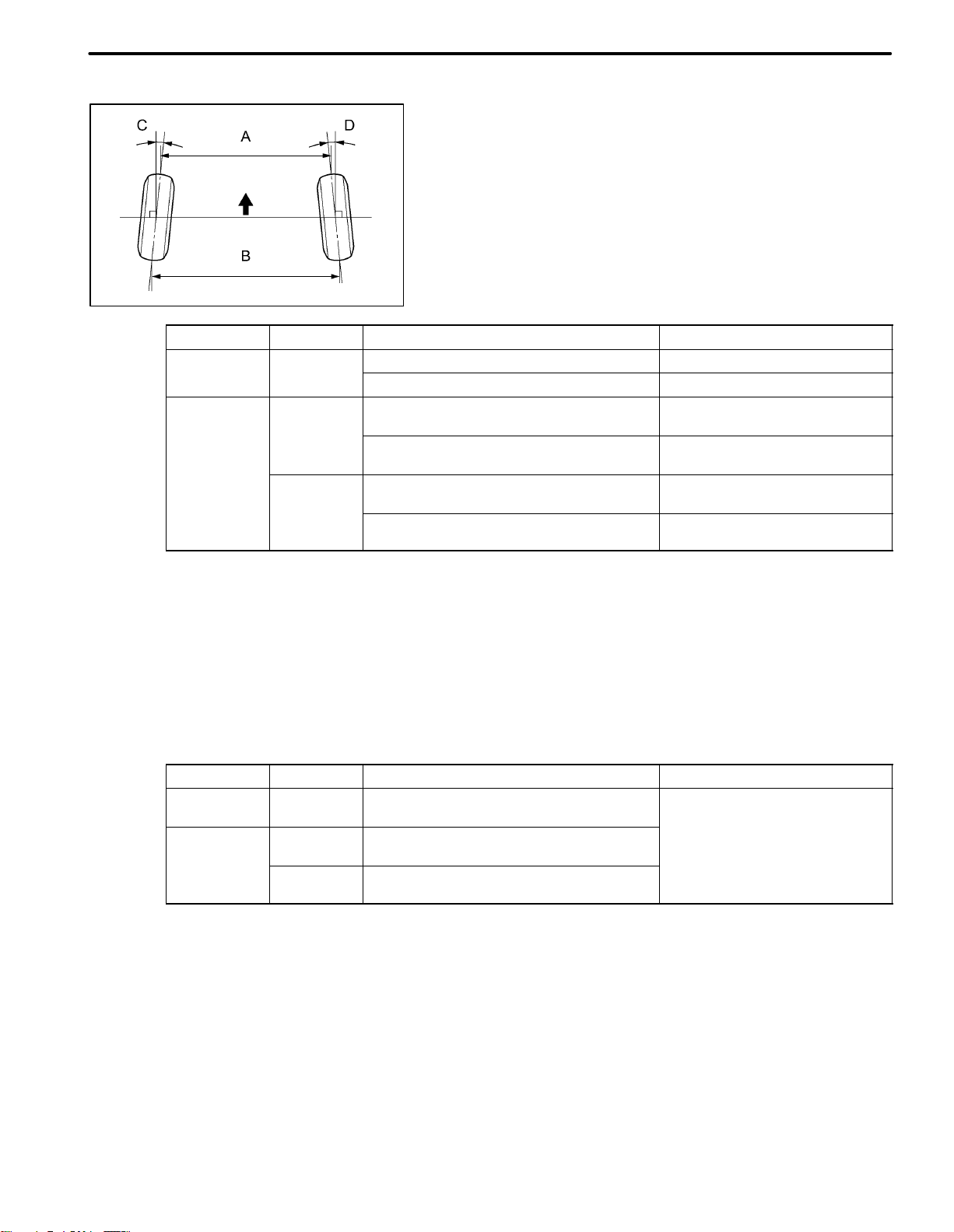
IN-36
INTRODUCTION
Tread Center
Mark
Front
Dimension A
Dimension B
C125225E04
Front
C162810E01
(6) Toe-in
HINT:
S Measure “B - A” only when “C + D” cannot be
measured.
S If toe-in is not within the specified range, adjust it
at the rack ends.
Specified Condition
C + D: 0_00’ +/-0_12’ (0_ +/-0.2_)
B - A: 0 +/-2.0 mm (0 +/-0.08 in.)
Page 56
(b) REAR WHEEL ALIGNMENT
Front
C132438E08
– Grade Specified Condition Right-Left Difference
for TMC Made except XRS
except XRS
except TMC
Made
for XRS
C + D: 0_16’ +/-0_15’ (0.27_ +/-0.25_) 45’ (0.75_) or less
B - A: 2.5 +/- 2.5 mm (0.098 +/-0.098 in.) –
C + D: 0_16’ +/-0_15’ (0.27_ +/-0.25_)
C + D: 0_16’ +/-0_15’ (0.27_ +/-0.25_)*
B - A: 2.6 +/-2.5 mm (0.102 +/-0.098 in.)
B - A: 2.0 +/-2.5 mm (0.0787 +/-0.098 in.)*
C + D: 0_16’ +/-0_15’ (0.27_ +/-0.25_)
C + D: 0_16’ +/-0_15’ (0.27_ +/-0.25_)*
B - A: 3.1 +/-2.5 mm (0.102 +/-0.098 in.)
B - A: 2.2 +/-2.5 mm (0.0866 +/-0.098 in.)*
INTRODUCTION
(6) Toe-in (Unloaded Vehicle)
S Measure “B - A” only when “C + D” cannot be
measured.
IN-37
45’ (0.75_) or less
–
45’ (0.75_) or less
–
* for vehicle height for Mexico, add 15 mm (0.591
in.) If the toe-in is not within the specified range,
inspect the suspension parts and replace them if
necessary.
(2) Camber (Unloaded Vehicle)
HINT:
Camber is not adjustable. If the measurement is not
within the specified range, inspect the suspension
parts for damage and/or wear, and replace them if
necessary.
– Grade Specified Condition Right-Left Difference
for TMC Made except XRS
except TMC
Made
except XRS
for XRS
-1_28’ +/-30’ (-1.47_ +/-0.50_)
30’ (0.50_) or less
-1_27’ +/-30’ (-1.45_ +/-0.50_)
30’ (0.50_) or less
-1_28’ +/-30’ (-1.47_ +/-0.50_)
30’ (0.50_) or less
30’ (0.50_) or less
Page 57

IN-38
INTRODUCTION
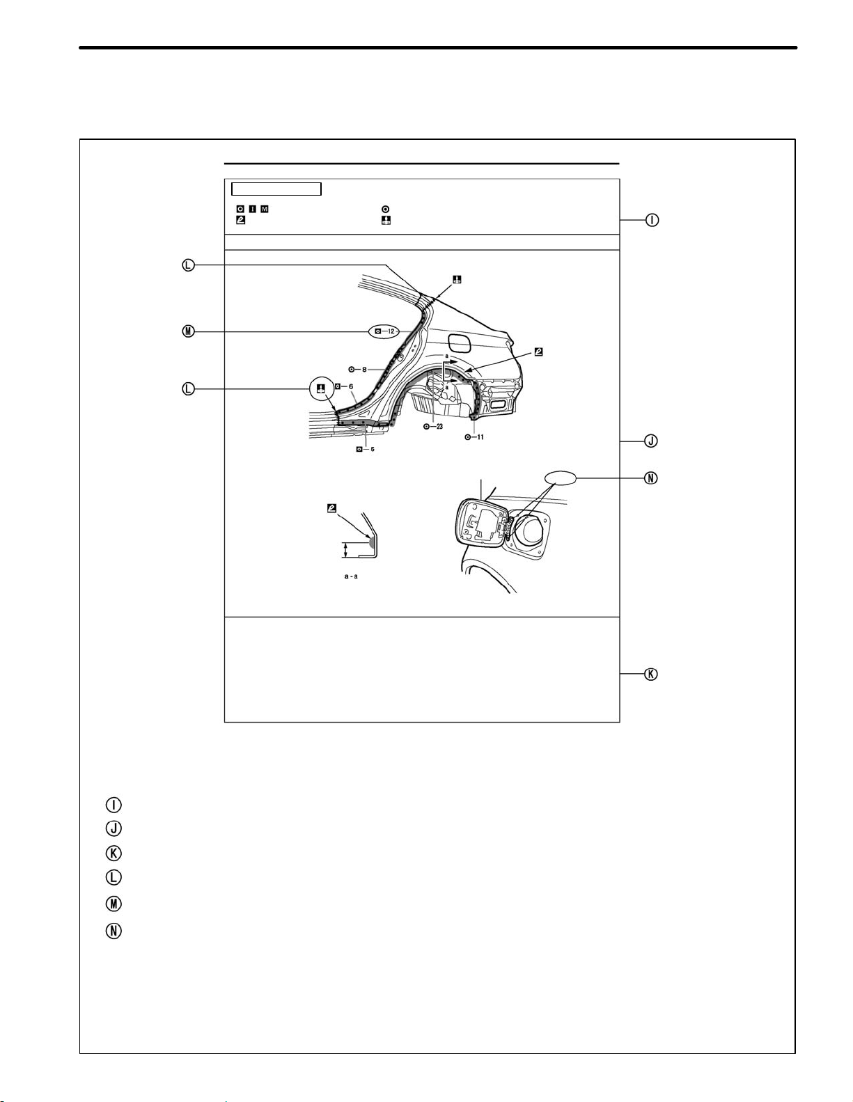
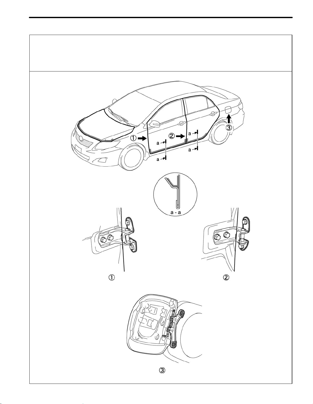
HOW TO USE THIS MANUAL
1. BODY PANEL REPLACEMENT IN THIS MANUAL
REMOVAL
BODY PANEL REPLACEMENT
QUARTER PANEL (CUT)
@ With the body lower back panel removed.
Symbol meaning
: Remove Weld Points
: Cut and Join Location
: Cut Location for Supply Parts
Fuel Filler Opening Lid
BP-34
150 (5.91)
REMOVAL POINT
1 Remove the Fuel Filler Opening Lid at the same time.
REPLACEMENT PART
QUARTER PANEL (CUT)
Replacement method
(ASSY) ...Assembly replacement
(CUT) ...Major cutting (less than 1 /2 of part used)
(CUT-H) ...Half cutting (about 1/ 2 of part used)
(CUT-P) ...Partial cutting (most of part used)
Replacement part
PART LOCATION
REMOVAL AND INSTALLATION CONDITIONS
SYMBOL MEANING
REMOVAL DIAGRAM
REMOVAL GUIDE
40
(1.57)
150 (5.91)
mm (in.)
WELDING EXPLANATION (See page IN-46)
SYMBOLS (See page IN-44)
B0608210134
Page 58
INTRODUCTION
IN-39
BP-38
Symbol meaning
: Mig Plug Weld
: Body Sealer
INSTALLATION
BODY PANEL REPLACEMENT
: Spot Weld
: Butt Weld
Fuel Filler Opening Lid
5
(0.20)
Rivets
INSTALLATION POINT
1 Before temporarily installing the new parts, apply body sealer to the wheel arch.
HINT:
1) Apply body sealer evenly about 5 mm (0.20 in.) from the flange, avoiding any oozing.
2) Apply sealer evenly, about 3 − 4 mm (0.12 − 0.16 in.) in diameter.
2 Temporarily install the new parts and measure each part of the new parts in accordance with
the body dimension diagram. (See the body dimension diagram)
3 After welding, apply body sealer and undercoating to the corresponding parts.
SYMBOLS
INSTALLATION DIAGRAM
INSTALLATION GUIDE
SYMBOLS (See page IN-44)
INSTALLATION OF WELD POINTS (See page IN-46)
PART NAME
mm (in.)
B0608210135
Page 59

2. SYMBOLS
INTRODUCTIONIN-40
REPAIR AREA
INDICATOR SYMBOLS
CUT
BRAZE
REPAIR METHOD
INDICATOR SYMBOLS
CUT AND JOIN
LOCATION
(Saw Cut)
CUT AND JOIN
LOCATION
(Cut Location for
Supply Parts)
CUT LOCATION
CUT WITH DISC
SANDER ETC.
BRAZING OR
ARC BRAZING
FOR REMOVAL
ILLUSTRATION
BRAZE
WELD
POINTS
WELDING
SEALER
BRAZE
SPOT WELD OR
PLUG WELD
(refer to
“ILLUSTRATION
OF WELD POINT
SYMBOLS”)
BUTT WELD
FILLET WELD
BODY SEALER
B0608210136
Page 60

INTRODUCTION
IN-41
REPAIR AREA
INDICATOR SYMBOLS
ASSEMBLY
MARK
BODY
SEALER
REPAIR METHOD
INDICATOR SYMBOLS
STANDARD HOLE
FOR INSTALLATION
FLAT FINISHING
NO FLAT FINISHING
ILLUSTRATION
B0608210137
Page 61

IN-42
INTRODUCTION
3. ILLUSTRATION OF WELD POINT SYMBOLS
REMOVAL INSTALLATION
Weld points
Position of panels that are removed
SYMBOLS
MEANING ILLUSTRATION
Remove Weld
Points
Position of Panel
Being Replaced is
on Outside
Position of Panel
Being Replaced is
in Center
Weld points
Welding method and panel position
SYMBOLS
MEANING
Spot Welding
Plug Welding
ILLUSTRATION
Position of Panel
Being Replaced is
on Inside
Spot MIG Welding
B0608210138
Page 62

PAINT S COATING
PC-1
BODY PANEL SEALING AREAS
Be sure to apply body sealer to the body panel joints and door edges (tip of outer panel folded part), etc., to waterproof and rustproof them.
HINT:
1) Apply degreasing agent to a clean cloth and clean the sealer application areas.
2) After removing the applied spot sealer from the sealer application areas using thinner or equivalent, rustproof the areas by applying primer or equivalent. Then apply body sealer.
3) If sealer is unnecessarily applied to an area, apply degreasing agent to a clean cloth and clean off the
sealer immediately.
Flat Finishing No Flat Finishing
1. ENGINE COMPARTMENT
[LH]
B0709250158
Page 63

PC-2
2. INSIDE
PAINT S COATING
B0709260006
Page 64

3. OUTSIDE
PAINT S COATING
PC-3
B0709250159
Page 65

PC-4
PAINT S COATING
B0709250160
Page 66
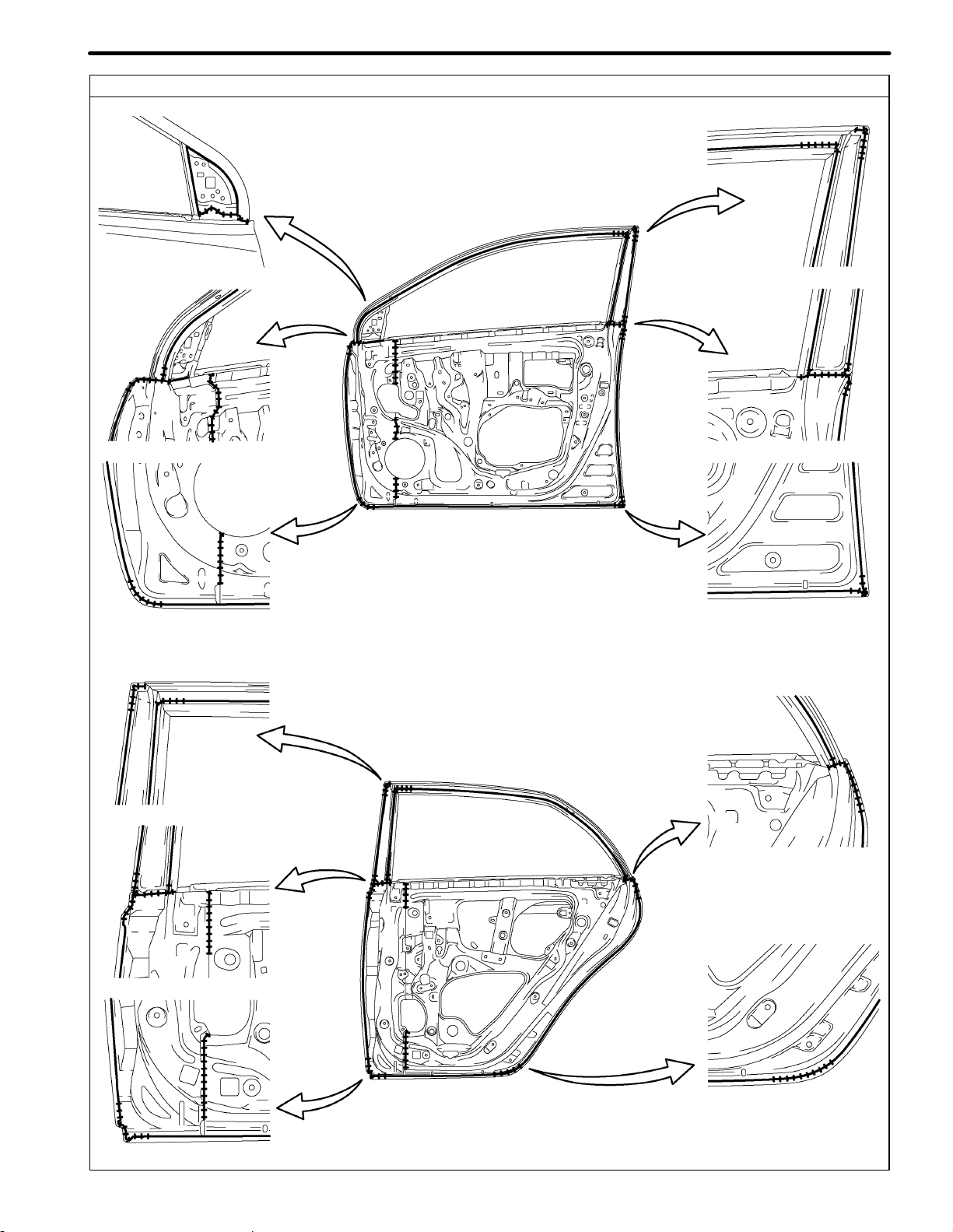
4. DOOR PARTS
PAINT S COATING
PC-5
B0709250161
Page 67

PC-6
PAINT S COATING
B0709250162
Page 68

PAINT S COATING
PC-7
BODY PANEL UNDERCOATING AREAS
Apply PASTAR UWE or PASTAR UC to the chassis, floor underside, sheet metal fitting weld points of the body, and
inside of the wheel house to prevent rust and noise, as well as protect the body from flying rocks.
HINT:
1) Work must be performed while wearing the appropriate protective gear and in a well-ventilated area.
2) Apply degreasing agent to a clean cloth and clean any dirt and oil from the application areas.
3) Cover the surrounding areas of the application areas with masking paper to avoid coating unnecessary
areas.
4) Do not coat high temperature areas, such as the tailpipe, or moving parts, such as the driveshaft.
5) Do not leave any gaps between the panel joints.
6) Apply sealer to the panel joints in advance.
HINT:
1) Parts coated using the PASTAR UWE should be left until dry to the touch in a 25_C environment for 60 to
75 minutes. Parts coated using PASTAR UC should be left until dry to the touch in a 25_C environment
for 15 to 30 minutes.
2) If using a PASTAR gun, one spray applies a 0.5 mm thick coating.
3) PASTAR UWE: Part number V9240-0025 PASTAR UC: Spray type :Part number V9240-0008
Aerosol type: Part number V9240-0021
Front
Rear
Rear
Front
B0710040023
REFERENCE
The undercoating should be applied according to the specifications for your country while referring to the notes
above.
Page 69

PC-8
PAINT S COATING
FOAMED MATERIAL APPLICATION AREAS
If an increase in temperature or other condition damages the foamed material when repairing or replacing the panel,
fill in the insufficient areas with urethane foam. The following illustration shows the areas for one side, but the
foamed material must be applied equally to both the left and right sides.
HINT:
1) Work must be performed while wearing the appropriate protective gear and in a will-ventilated area.
2) Apply tape or equivalent to any holes, nuts, etc., near the areas to be filled.
B0709250165
Page 70
PAINT S COATING
PC-9
BODY PANEL ANTI-RUST AGENT (WAX) APPLICATION AREAS
Apply RUSTOP W to the doors and hood edges (tips of outer panel folded parts) and undersides, areas around
hinges, etc.to prevent rust. Coat the undersides of the edges using a nozzle and air gun, and coat the areas around
the hinges using a brush.
HINT:
1) If RUSTOP is unnecessarily applied to an area, apply degreasing agent to a clean cloth and clean off the
RUSTOP immediately.
B0709250166A
Page 71

PAINT S COATINGPC-10
SILENCER SHEET INSTALLATION AREAS
Substitute silencer sheets for the laminate coat application areas.
Thicknee of Silencer Sheet mm (in.)
. . .
1.5 (0.06)
. . .
2.0 (0.08)
. . .
3.0 (0.12)
B0710040024
 Loading...