

Page 1
Page 1 of 7Central locking system (Avant), repairin
g
57-50
Central locking system (Ava nt),
repairing
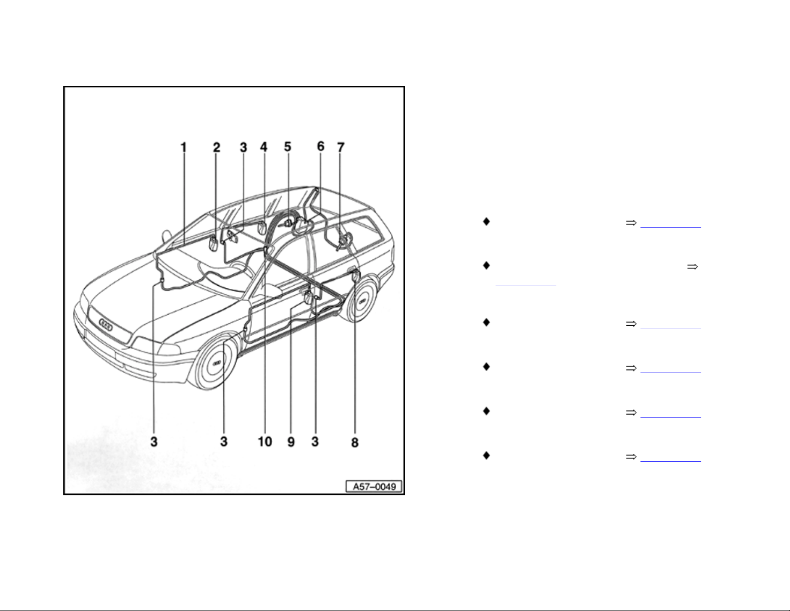
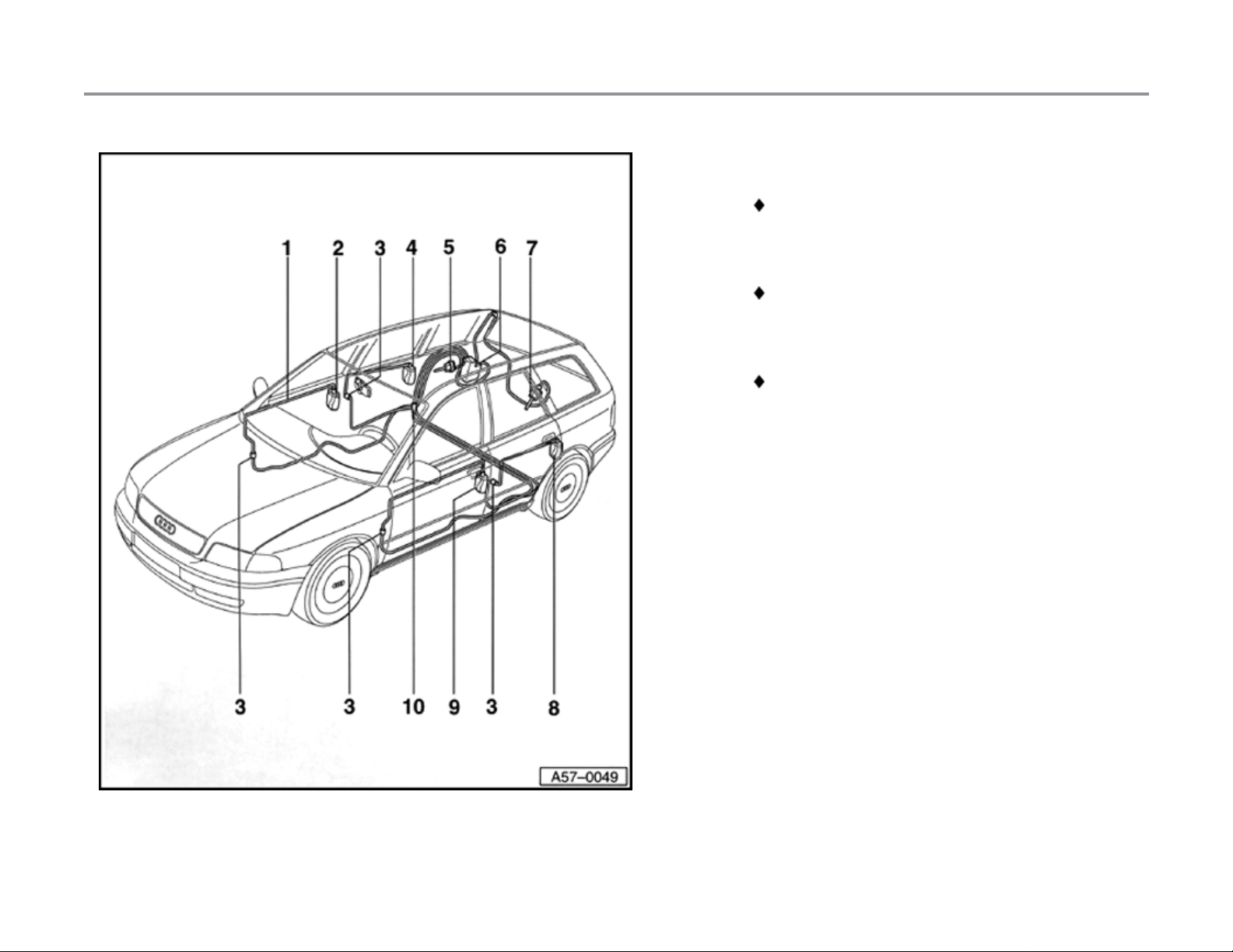
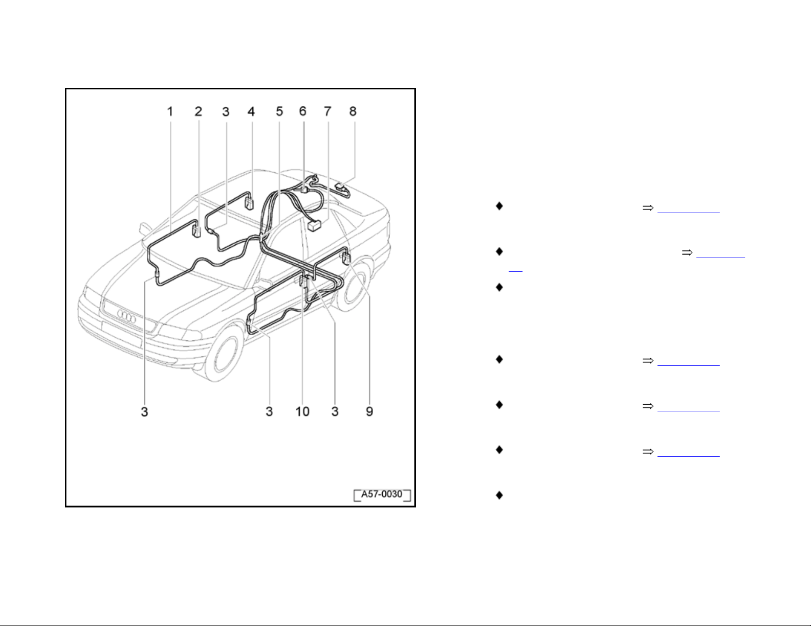
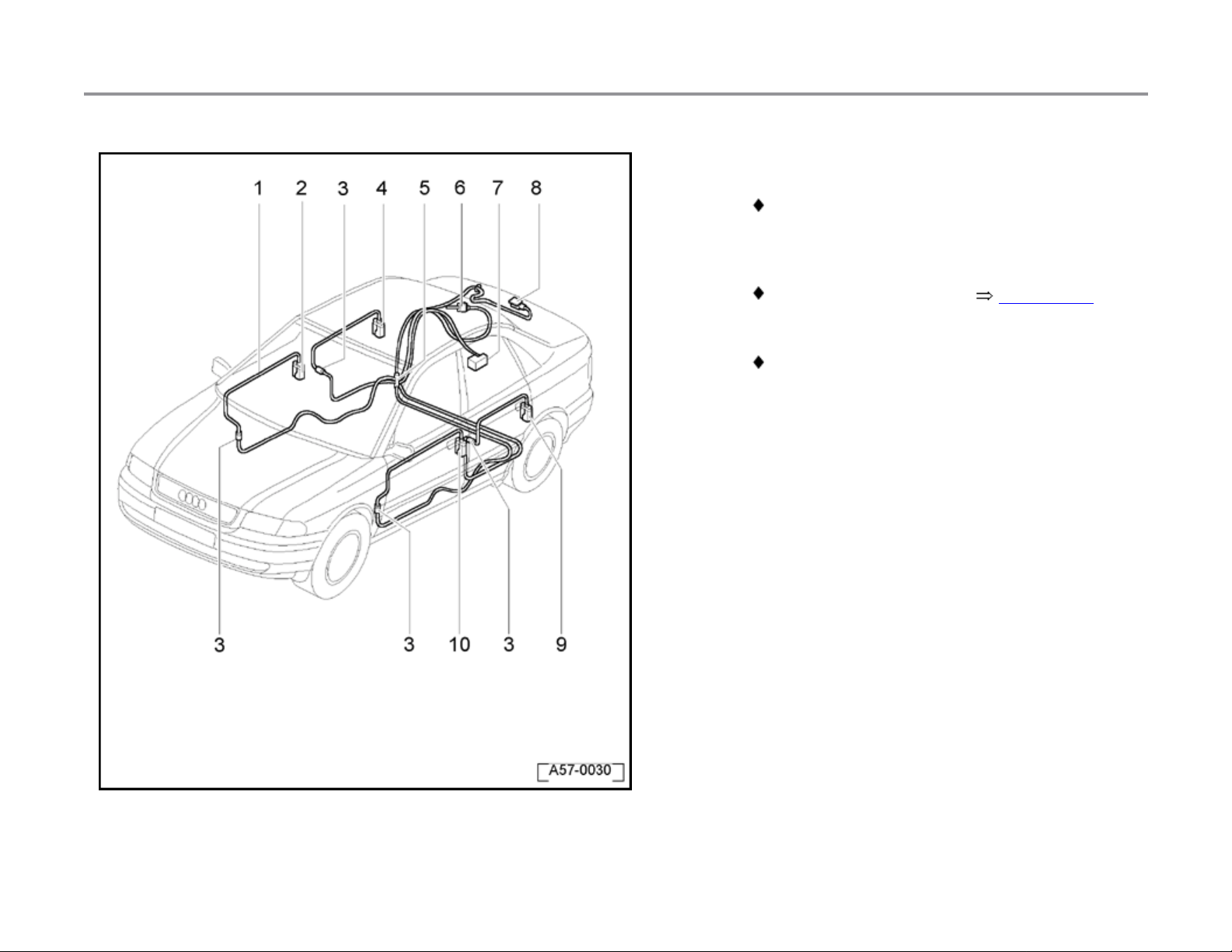
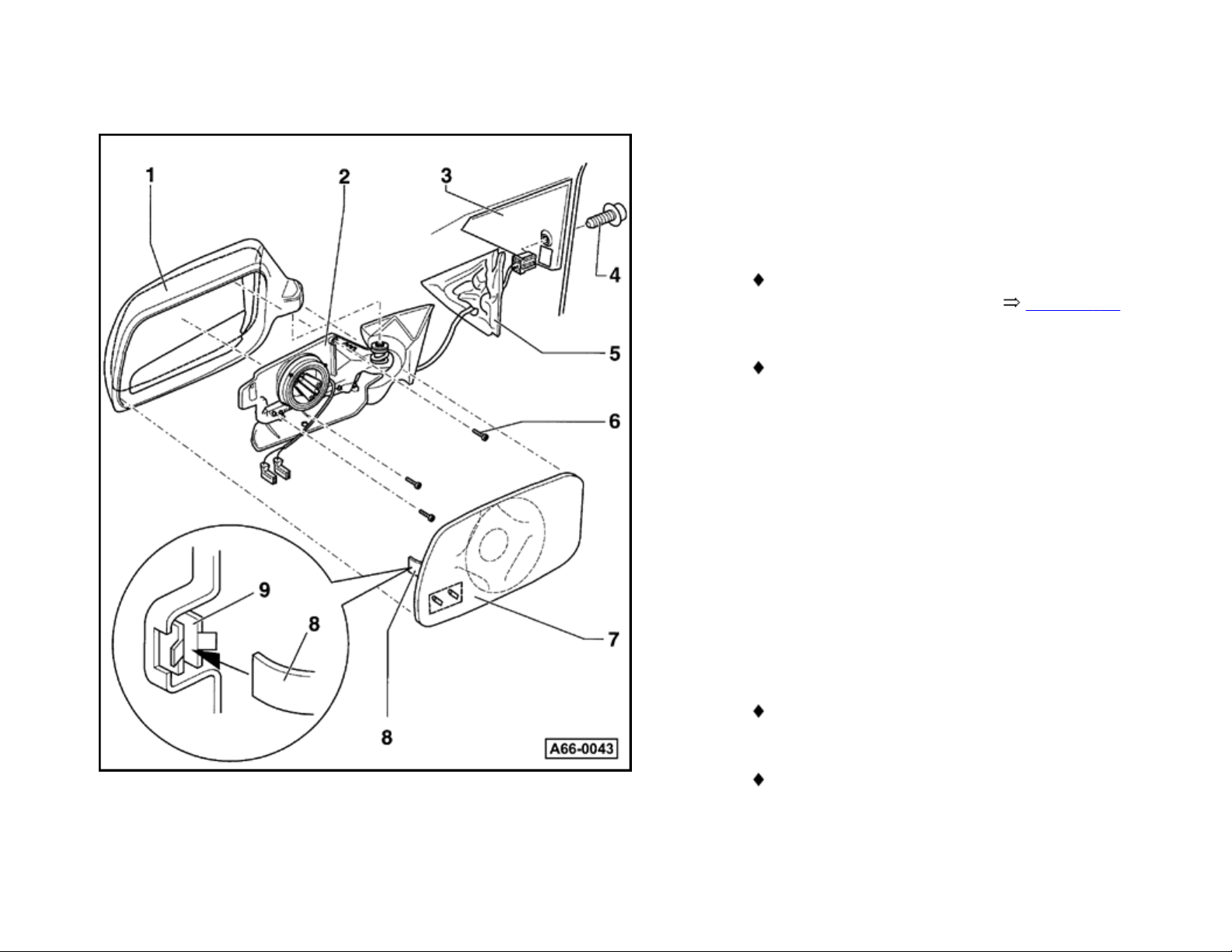
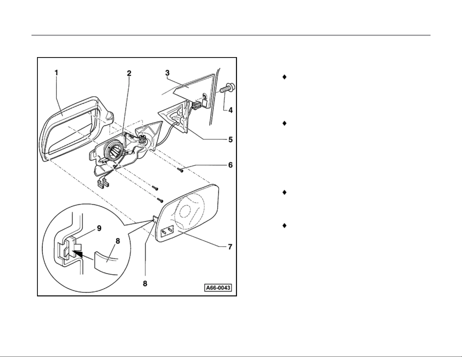
Assembly overview
1 - Pressure and vacuum lines
2 - Right-front door actuator valve
Removing and installing page 57-12
3 - Vacuum line connectors
Disconnect vacuum line connectors
page 57-42
4 - Right-rear door actuator valve
Removing and installing page 58-14
5 - Fuel filling flap lock actuator
Removing and installing page 57-52
6 - Central locking system pump
Removing and installing page 57-56
7 - Rear lid lock actuator
Removing and installing page 57-53
11/21/2002http://127.0.0.1:8080/audi/servlet/Display?action=Goto&type=repair&id=AUDI.B5.BD01.57.9
Page 2
Page 2 of 7Central locking system (Avant), repairin
g
57-51
8 - Left-rear door actuator valve
Removing and installing same as for right
door
9 - Left-front door lock actuator
Removing and installing same as for right
door
10 - Distribution box
Connected with all other vac uum lines,
excluding lines for rear lid
11/21/2002http://127.0.0.1:8080/audi/servlet/Display?action=Goto&type=repair&id=AUDI.B5.BD01.57.9
Page 3
Page 3 of 7Central locking system (Avant), repairin
g
57-52
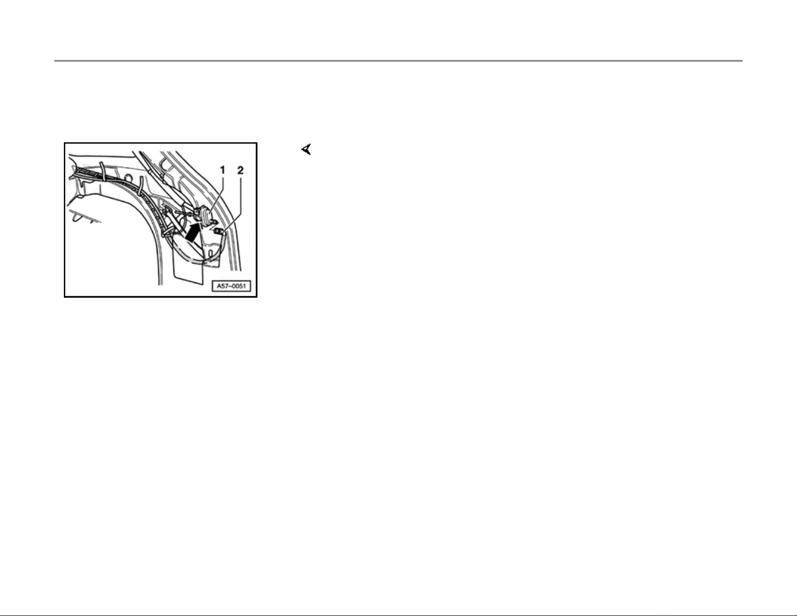
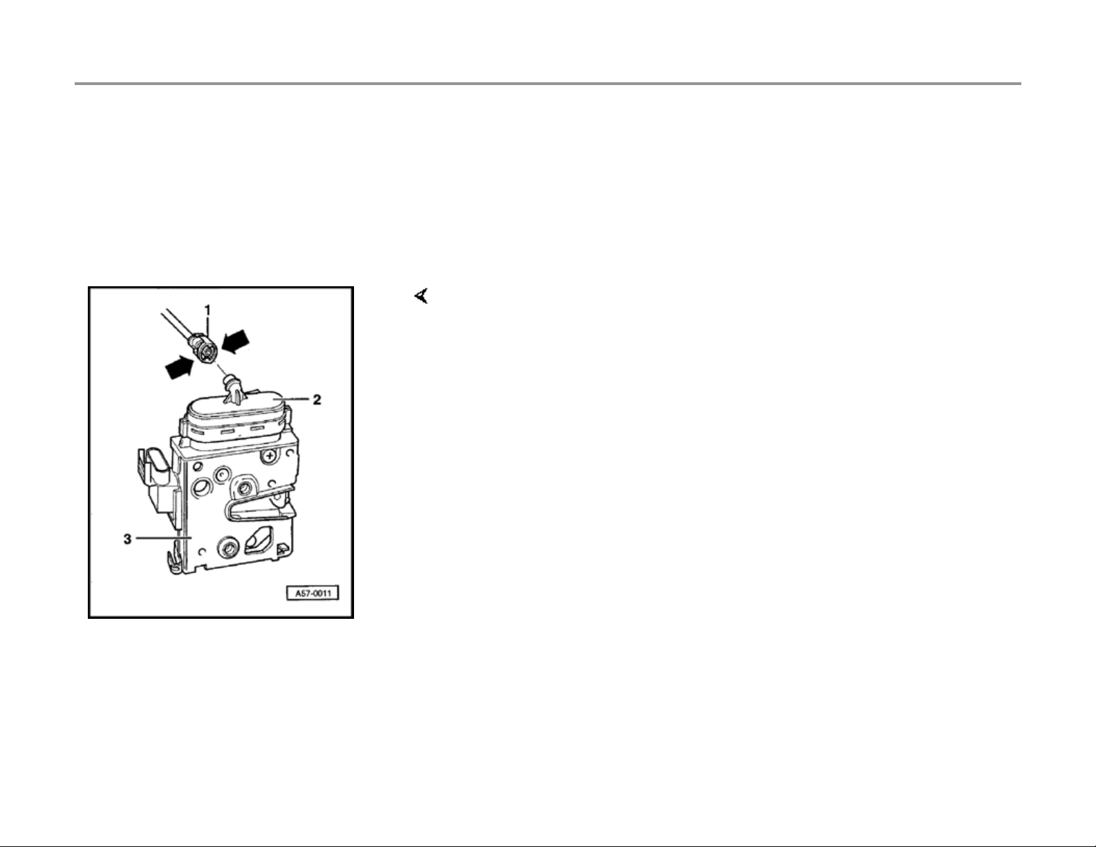
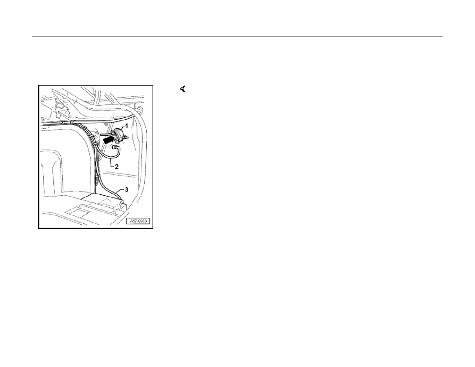
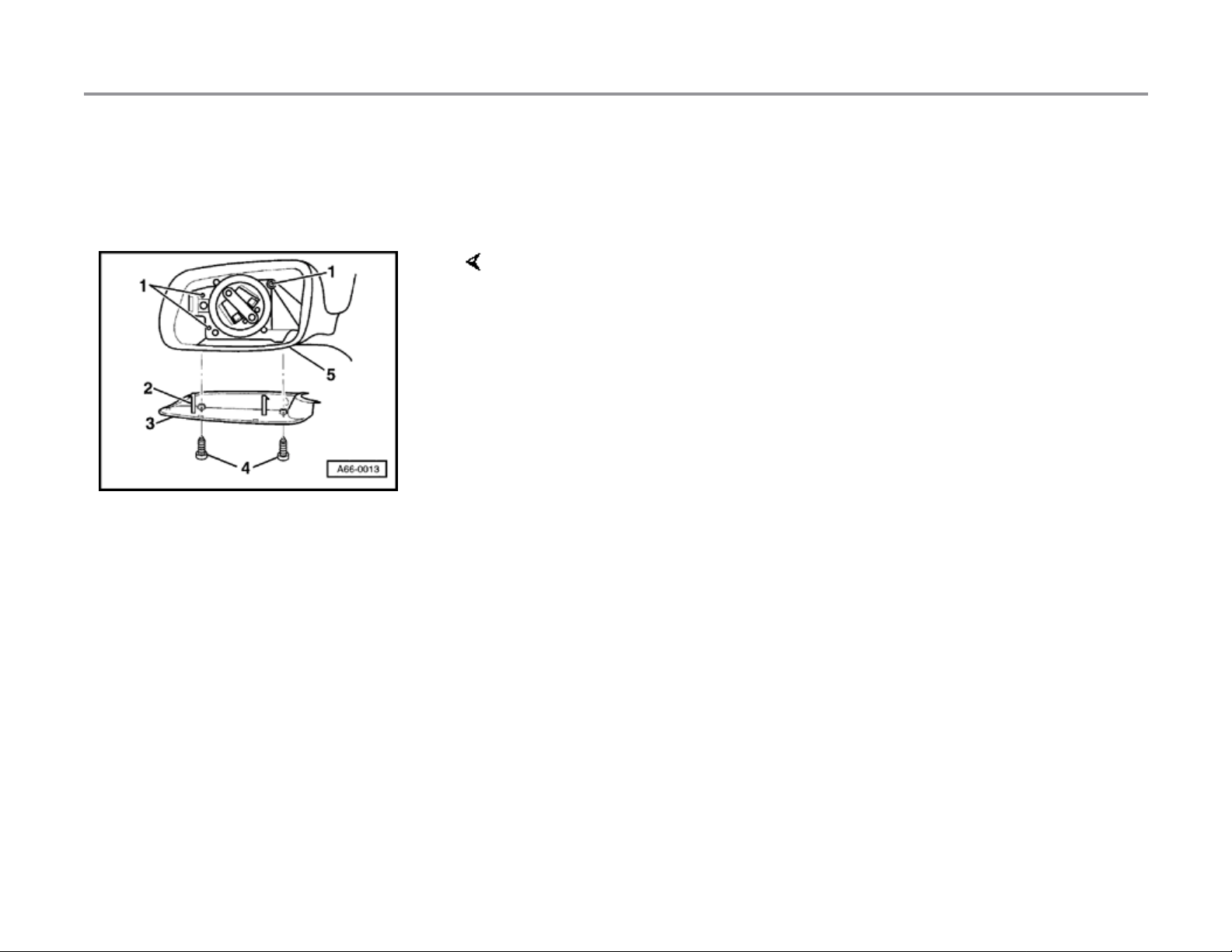
Fuel filling flap lock actuator, removing
and installing
- Disengage locking mechanism from angled plug and detach vacuum
line -2- from lock actuator -1-.
- To remove, press in locking lug (arrow) and pull lock actuator -1rearward and out.
- To install, push into case until snap indicates engagement.
11/21/2002http://127.0.0.1:8080/audi/servlet/Display?action=Goto&type=repair&id=AUDI.B5.BD01.57.9
Page 4
Page 4 of 7Central locking system (Avant), repairin
g
57-53
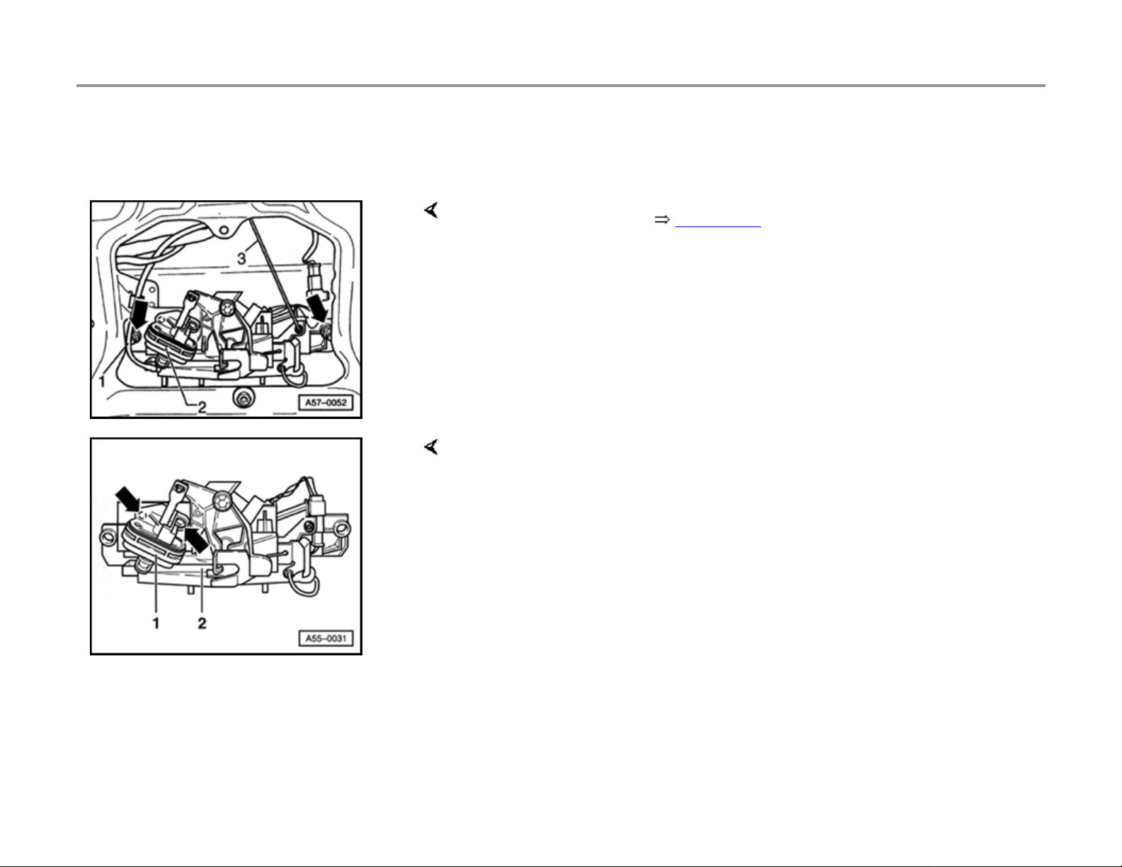
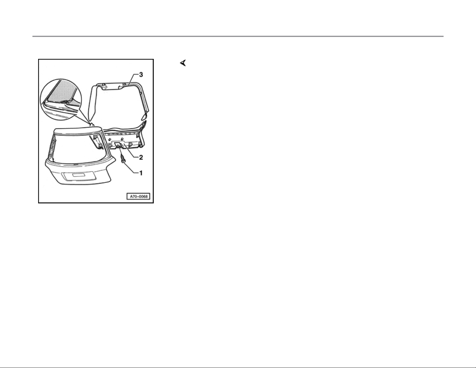
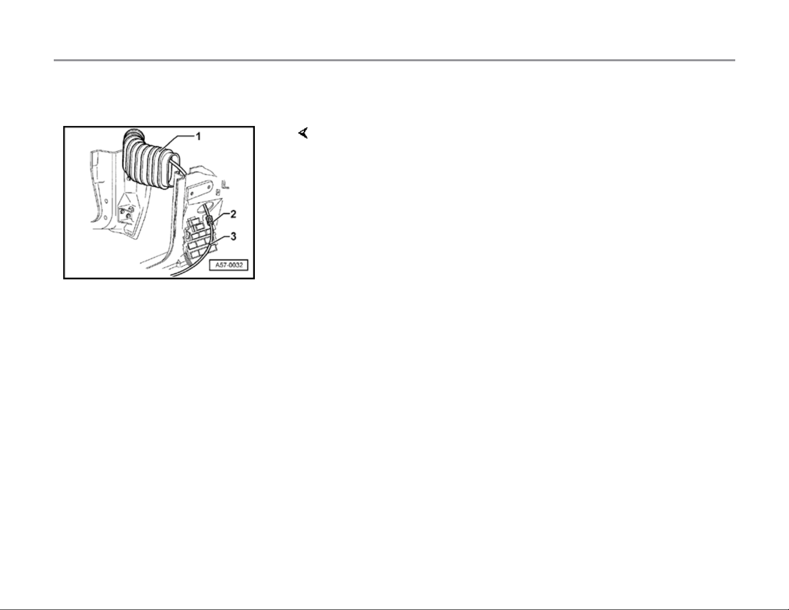
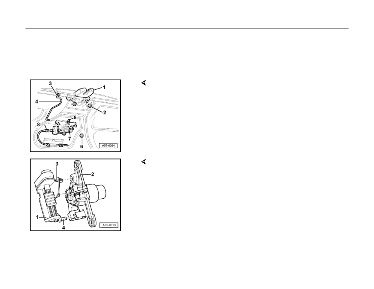
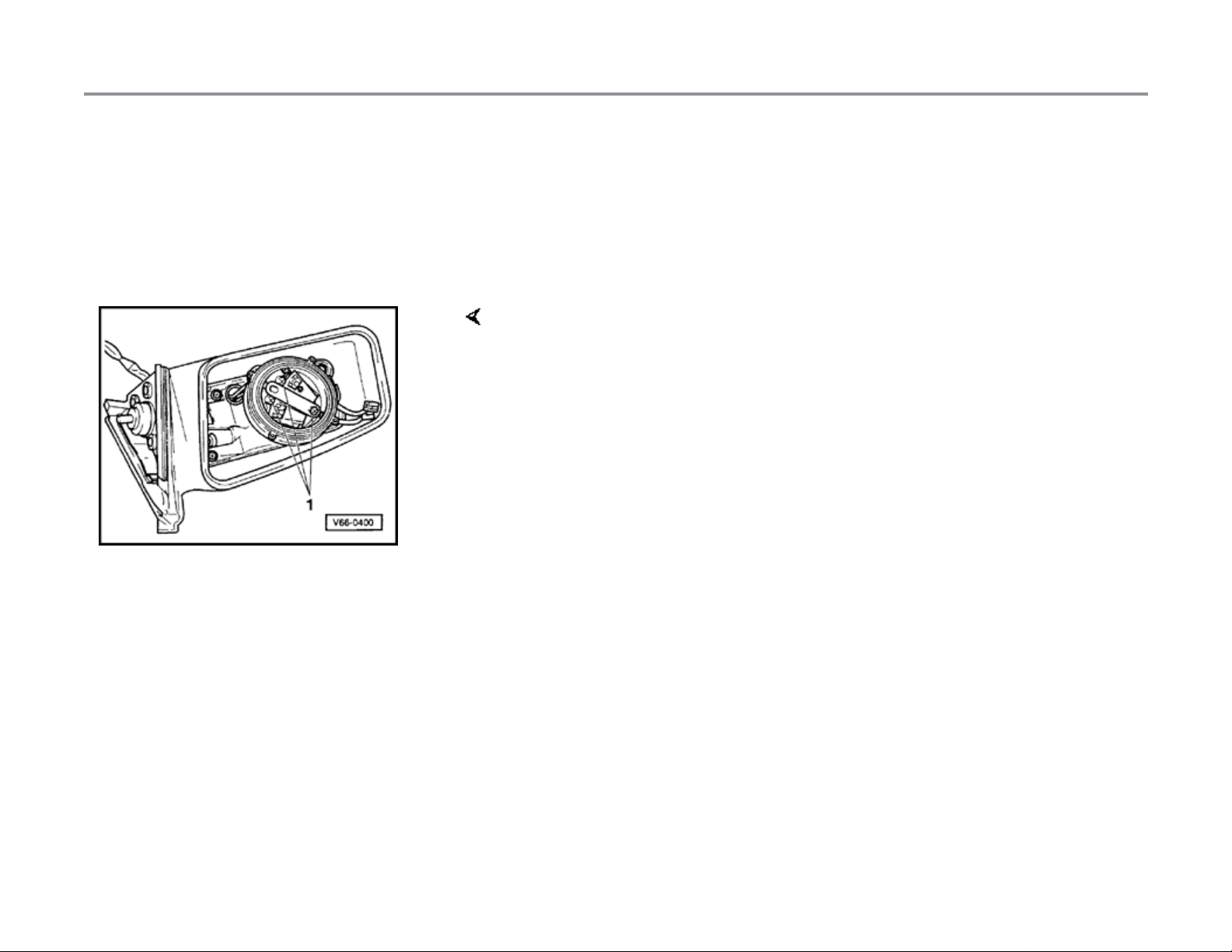
Rear lid lock actuator, removing and
installing
- Remove tailgate trim page 57-54 .
- Disengage lock system at plug for vacuum line -1- and remove from
lock actuator -2-.
- Press clamping pins (arrow) out and remove lock actuator -1- from lock
-2-.
- Clamping pins mu st be snapped back into expandi ng clips during
installation.
- Pry out using screwdriver if necessary.
Note:
Illustration shows component after removal.
11/21/2002http://127.0.0.1:8080/audi/servlet/Display?action=Goto&type=repair&id=AUDI.B5.BD01.57.9
Page 5
Page 5 of 7Central locking system (Avant), repairin
g
57-54
Fig. 1 Removing and installing tailgate trim
- Remove bolt -1-fro m han dl e well.
Torque: 1.5 Nm + 0.5 Nm (13 in. lb + 4 in. lb)
- Unclip lower rear hatch trim -2-.
- Unclip upper rear hatch trim -3-.
Note:
When installing the lower trim, guide bars must be inserted in upper trim.
11/21/2002http://127.0.0.1:8080/audi/servlet/Display?action=Goto&type=repair&id=AUDI.B5.BD01.57.9
Page 6
Page 6 of 7Central locking system (Avant), repairin
g
57-55
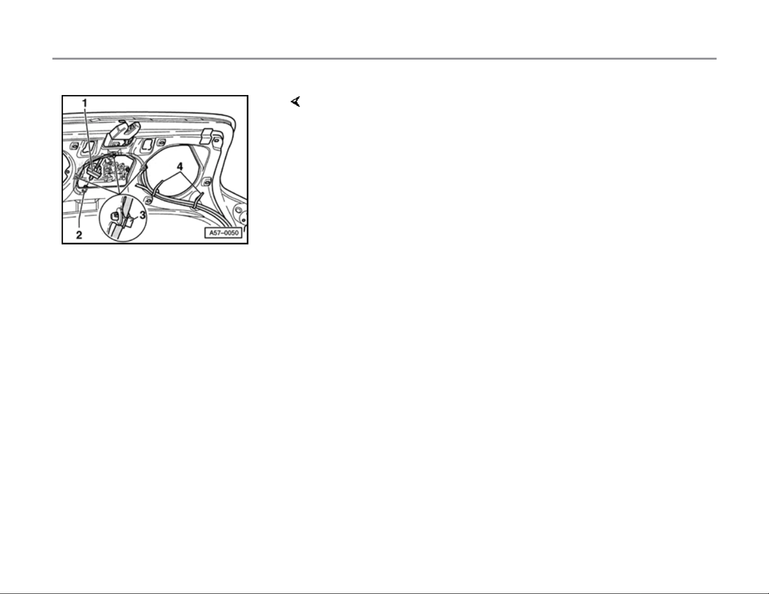
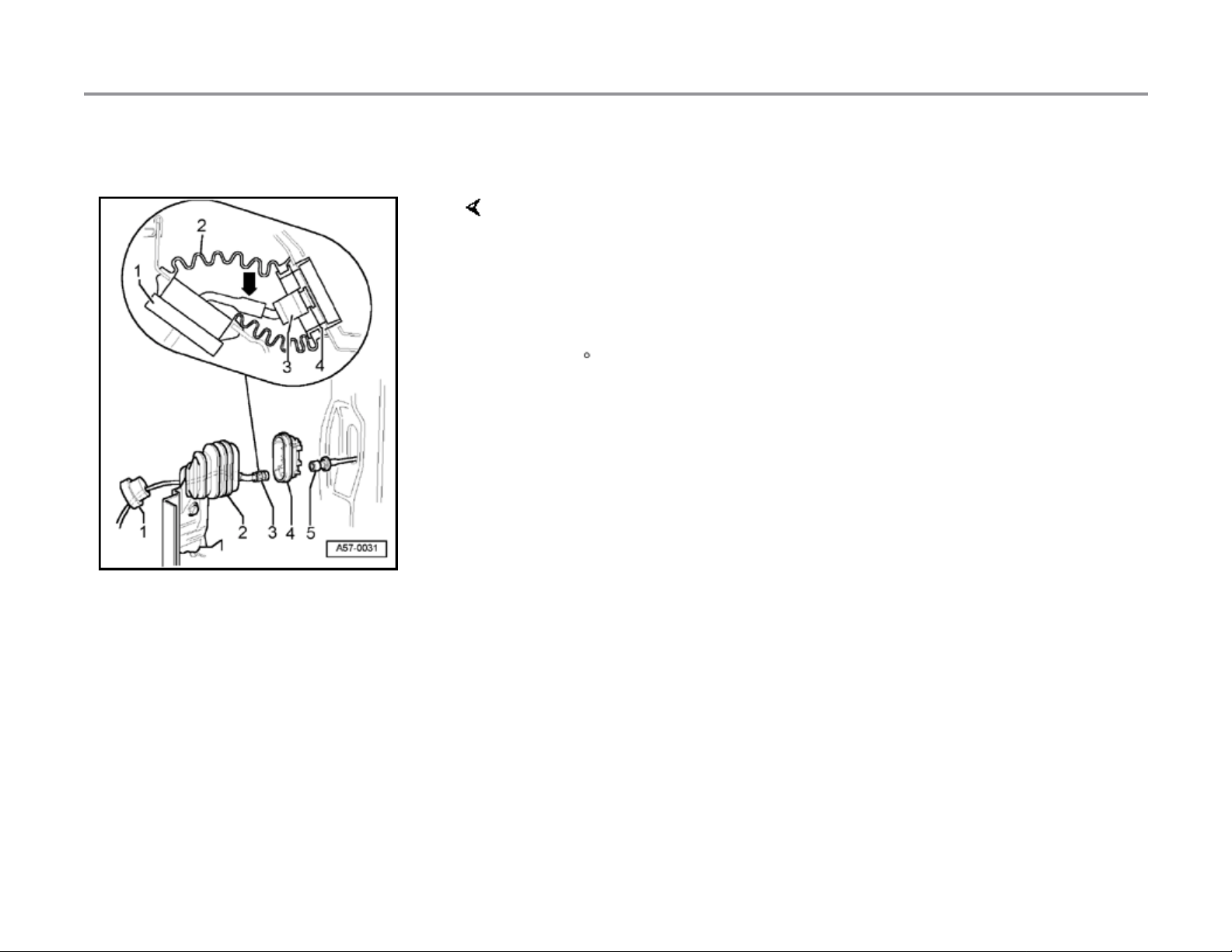
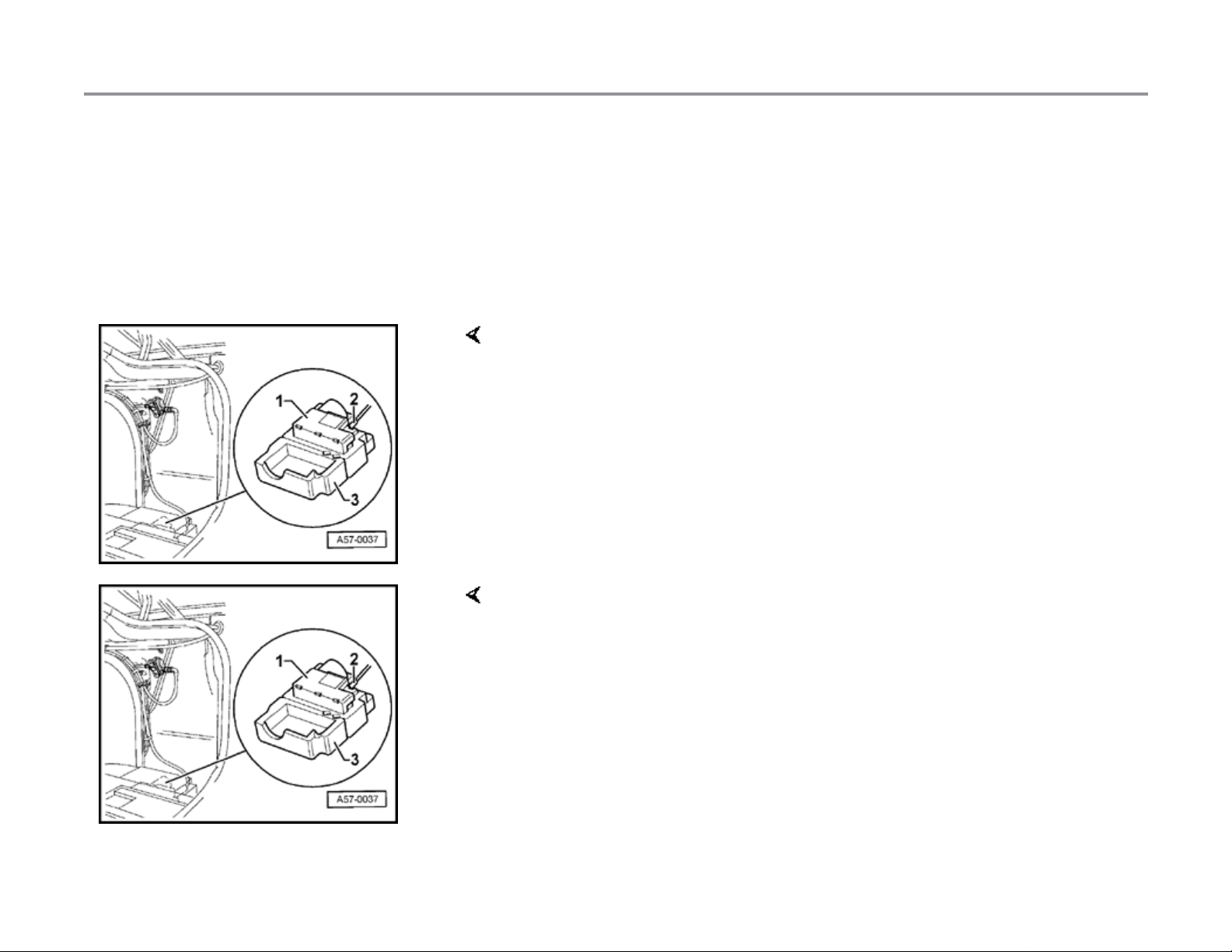
Fig. 2 Line routing
- Route pressure and vacuum lines through tie wraps -4- as shown in
diagram and snap into clips -3-.
- Snap harness connector -2- into lock actuator.
11/21/2002http://127.0.0.1:8080/audi/servlet/Display?action=Goto&type=repair&id=AUDI.B5.BD01.57.9
Page 7
Page 7 of 7Central locking system (Avant), repairin
g
57-56
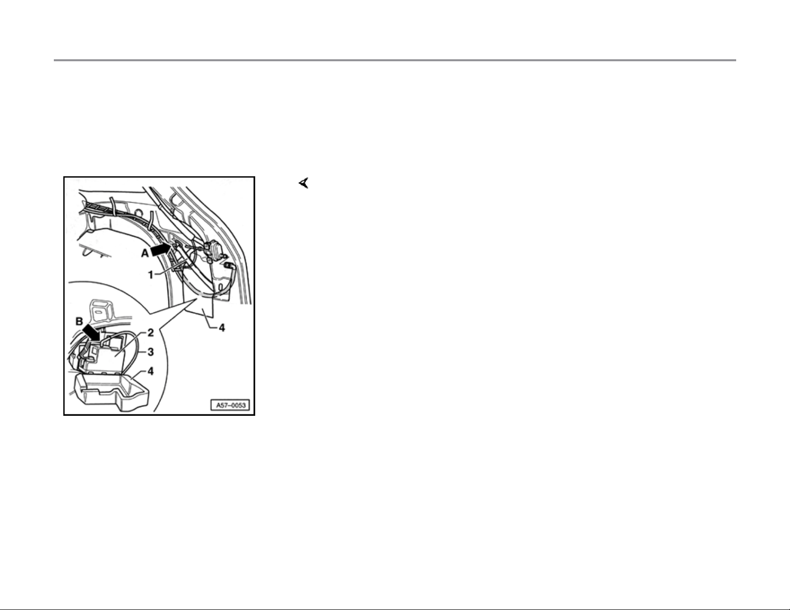
Central locking system pump, removing
and installing
- Remove cover on side trim panel.
- Unhook tension strap -1- at arrow -A-.
- Remove insulation -4- with pump for central locking system -2- from
side panel.
- Fold back insulation and remove pump.
- Disengage vacuum line connectors and detach angled plug (arrow B-).
CAUTION!
After disconnecting all three vacuum line connectors from the
central locking system pump, ensure that the middle 6-pin harness
connector (power supply) is always plugged in last.
11/21/2002http://127.0.0.1:8080/audi/servlet/Display?action=Goto&type=repair&id=AUDI.B5.BD01.57.9
Page 8
Page 1 of 11Central locking system
57-39
Central locking system
Assembly overview
1 - Vacuum line
2 - Right-front door lock actuator
Removing and installing page 57-12
3 - Vacuum line connectors
Disengage harness connectors page 57-
42
Additional vacuum line connectors are
located at bottom of A-pillar and in boot at
B-pillar
4 - Right-rear door lock actuator
Removing and installing page 58-14
5 - Fuel filler flap lock actuator
Removing and installing page 57-46
6 - Central locking system pump
Removing and installing page 57-49
7 - Distribution box
Connected with all other wires excluding
wire for rear lid
11/21/2002http://127.0.0.1:8080/audi/servlet/Display?action=Goto&type=repair&id=AUDI.B5.BD01.57.8
Page 9
Page 2 of 11Central locking system
57-40
8 - Left-front door lock actuator
Removing and installing same as for right
door
9 - Rear lid lock actuator
Removing and installing page 57-47
10 - Left-rear door lock actuator
Removing and installing same as for right
door
11/21/2002http://127.0.0.1:8080/audi/servlet/Display?action=Goto&type=repair&id=AUDI.B5.BD01.57.8
Page 10

Page 3 of 11Central locking system
57-41
Repairing central locking system
For additional information Electrical Wiring
Diagrams, Troubleshooting & Component
Locations binder.
Notes:
After the car has been parked for a lengthy time
and/or after replacing the central locking system
pump, the central locking system will not
function properly until prompted repeatedly.
When the system is operating correctly, all
locks will close within 2 seconds.
If the pump operates for longer than 5 seconds,
there is a leak in the system.
When there is a leak in the system, the pump
must not run for more than 30 seconds. The
pump's control unit must shut it off at this point.
All the lock actuators are equipped with special
vacuum line connectors that must lock when
plugged in.
11/21/2002http://127.0.0.1:8080/audi/servlet/Display?action=Goto&type=repair&id=AUDI.B5.BD01.57.8
Page 11
Page 4 of 11Central locking system
57-42
Vacuum line connectors, disengaging
Note:
Do not simply pull on the lock actuators to
disconnect; the locking mechani sm in stall ed on
the harness connector must first be disengaged.
- To disengage lock, squeeze harness connector on locking mechanism
at arrows.
- Disconnect harness connector.
11/21/2002http://127.0.0.1:8080/audi/servlet/Display?action=Goto&type=repair&id=AUDI.B5.BD01.57.8
Page 12

Page 5 of 11Central locking system
57-43
Damaged vacuum line, repairing
- Remove damaged area using knife.
- Cut connecting line e.g. ET-Nr 533 862 225 to
proper length and push onto vacuum line.
11/21/2002http://127.0.0.1:8080/audi/servlet/Display?action=Goto&type=repair&id=AUDI.B5.BD01.57.8
Page 13
Page 6 of 11Central locking system
57-44
A-pillar vacuum line connector
- After removing lower A-pillar cover, vacuum line connector -2becomes accessible at bottom of A-pillar.
1 - Boot
3 - Line to distribution box
11/21/2002http://127.0.0.1:8080/audi/servlet/Display?action=Goto&type=repair&id=AUDI.B5.BD01.57.8
Page 14
Page 7 of 11Central locking system
57-45
B-pillar vacuum line connector
- Assemble seal -1- with cable slot at bottom.
- After removing boot -2-, vacuum line connector -3- can be removed by
disengaging locking mechanism from line -5-.
Note:
The 45 plug (arrow) must point toward front of vehicle.
11/21/2002http://127.0.0.1:8080/audi/servlet/Display?action=Goto&type=repair&id=AUDI.B5.BD01.57.8
Page 15
Page 8 of 11Central locking system
57-46
Lock actuator for fuel filling flap,
removing and installing
- Disengage locking mechanism from angled plug and detach vacuum
line -2-.
- To remove, press in locking lug arrow and pull lock actuator -1rearward and out.
3 - Vacuum line to the pump for central locking system
11/21/2002http://127.0.0.1:8080/audi/servlet/Display?action=Goto&type=repair&id=AUDI.B5.BD01.57.8
Page 16
Page 9 of 11Central locking system
57-47
Rear lid lock actuator, removing and
installing
Removing
- Separate harness connector and detach vacuum line.
- Disengage operating rod -4- from clip -3-.
- Remove hex nuts -6- and remove lock actuator -7- from rear lid lock.
- Push out retaining pin -3- (2x) remove expanding clip.
- Push clip -4- back and disconnect.
- Remove lock actuator -1- from rear lid lock.
11/21/2002http://127.0.0.1:8080/audi/servlet/Display?action=Goto&type=repair&id=AUDI.B5.BD01.57.8
Page 17
Page 10 of 11Central locking system
57-48
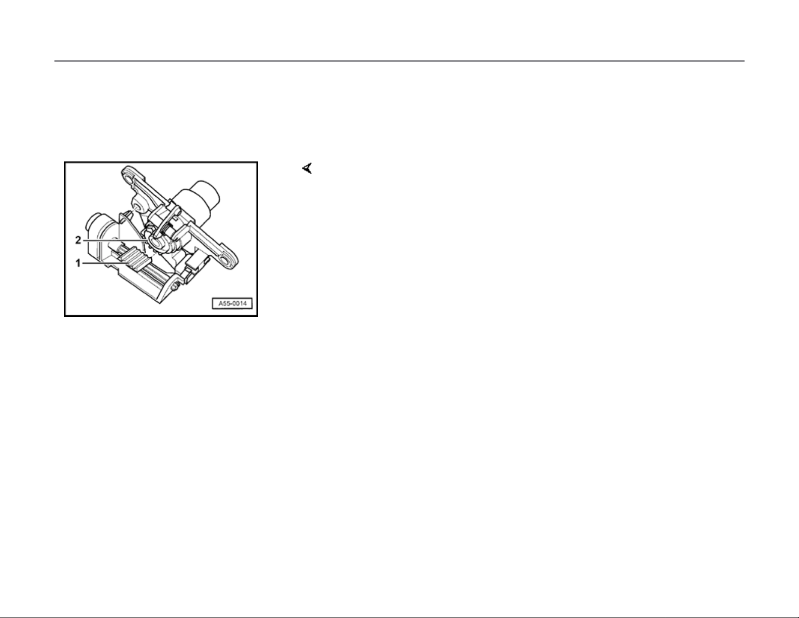
Installing
- Set lock cylinders in "open" position.
- Push ridged plate -1- to left. The first ridge of the plate -1- must snap
into the first groove on the grooved segment -2- .
11/21/2002http://127.0.0.1:8080/audi/servlet/Display?action=Goto&type=repair&id=AUDI.B5.BD01.57.8
Page 18
Page 11 of 11Central locking system
57-49
The pump for the central locking system is
Central locking system pump, removing
and installing
located in the right-rear of the luggage
compartment under the luggage compartment
trim.
- Fold back luggage compartment trim and remove insulation -3- with
pump for central locking system -1-.
- Disengage connecting line -2-.
- Open insulation, disengage electrical harness connectors and remove
connector -2- for vacuum line.
CAUTION!
After disconnecting all three connectors from the central locking
system pump, ensure that the middle 6-pin connector (for power
supply) is always plugged in last.
11/21/2002http://127.0.0.1:8080/audi/servlet/Display?action=Goto&type=repair&id=AUDI.B5.BD01.57.8
Page 19
Page 1 of 4Door mirrors
66-14
Door mirrors
Door mirrors, removing and installing
1 - Mirror housing
Can be removed from door without
removing mirror comp letely page 66-16
2 - Mirror adjustor
Before removing, remove mirror from door
- To remove, pry off mirror glass,
disconnect harness connectors for mirror
Note:
On vehicles with seat memory, door trim must be
removed before removing mirror adjustor.
3 - Door component carrier
heating, remove phillips head screws -6and take mirror adjustor -1- out of mirror
housing.
4 - Socket head screw
12 Nm (9 ft lb)
5 - Seal
Check for correct fit during installation.
11/20/2002http://127.0.0.1:8080/audi/servlet/Display?action=Goto&type=repair&id=AUDI.B5.BD01.66.8
Page 20
Page 2 of 4Door mirrors
66-15
6 - Phillips head screw
1 Nm (9 in. lb)
7 - Mirror glass
- To remove, use s pecial tool 80-200
(assembly lever).
Use fabric reinforced adhesive tape at top
and bottom to protect mirror housing from
paint damage
- Pry mirror out at bottom first, then top.
- To install, first insert mirror lens into
guide stud and friction finger in friction
spring, then press on.
Apply pressu re only to center of lens;
always wear protective gloves
8 - Friction finger
Friction finger -8- must be pushed into
friction spring -9- whe n in serting mirror
glass in housing
9 - Friction spring
11/20/2002http://127.0.0.1:8080/audi/servlet/Display?action=Goto&type=repair&id=AUDI.B5.BD01.66.8
Page 21
Page 3 of 4Door mirrors
66-16
Door mirror housing, replacing
- Remove mirror glass.
- Remove screws -4- (2x).
- Press back retainers -2- and take off cover -3- downward.
- Remove screws -1- at mirror adjusting unit (3x).
- Lift up housing -5- and remove.
11/20/2002http://127.0.0.1:8080/audi/servlet/Display?action=Goto&type=repair&id=AUDI.B5.BD01.66.8
Page 22
Page 4 of 4Door mirrors
66-17
Power mirror adjuster, replacing
- Disconnect battery.
- Remove mirror glass.
- Remove screws -1- (3x)
Tightening torque: 1 Nm (9 in. lb)
- For mirror adjusting units with harness connectors, these should be
removed before disassembl y.
Note:
For mirror adjusting units with soldered wires, these should be separated
individually directly at the housing.
- Install wiring into connector housing enclosed with replacement unit.
Note:
Transfer wire routing from old power mirror adjuster using correct wiring
diagram.
11/20/2002http://127.0.0.1:8080/audi/servlet/Display?action=Goto&type=repair&id=AUDI.B5.BD01.66.8
Page 23
Page 1 of 8Rear bumper (Avant
)
63-16
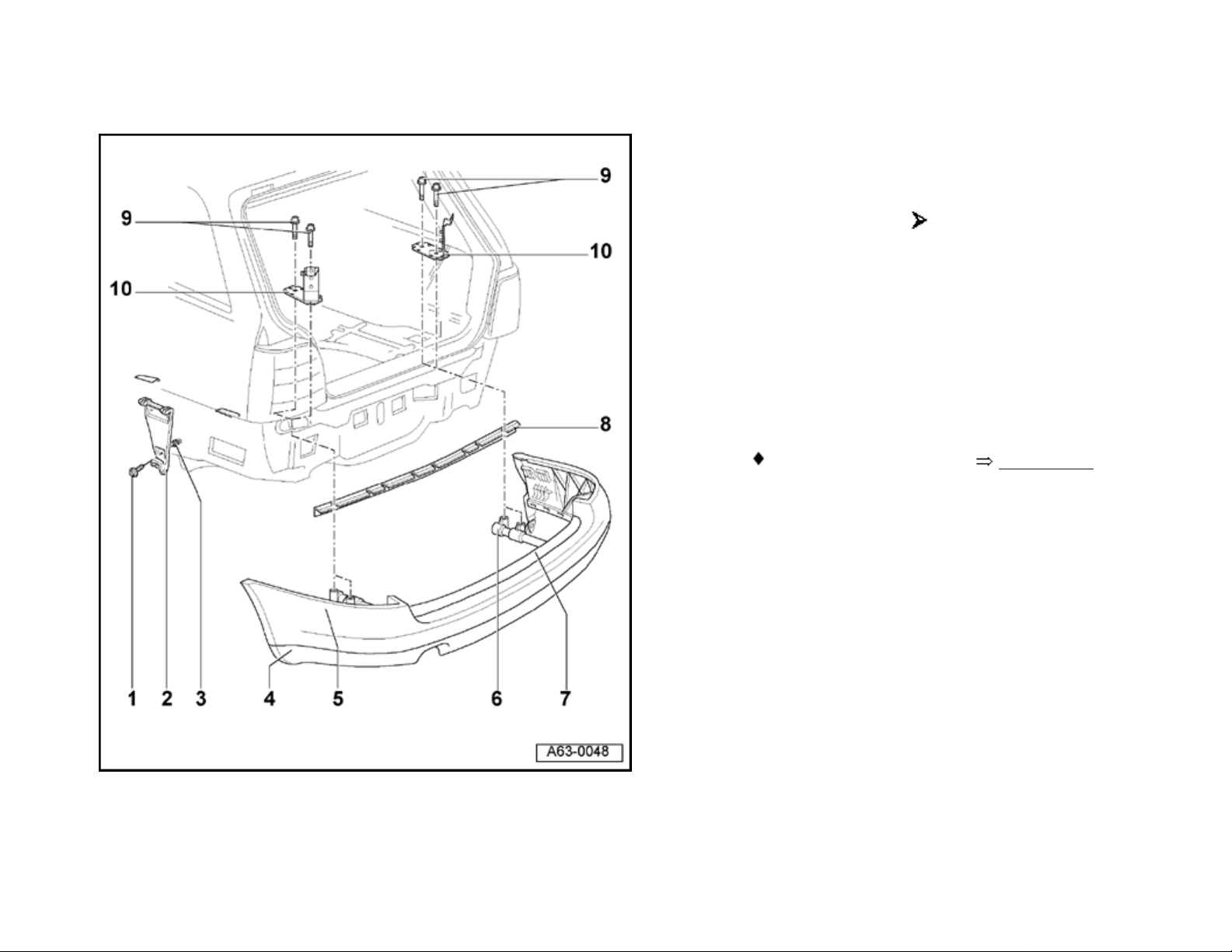
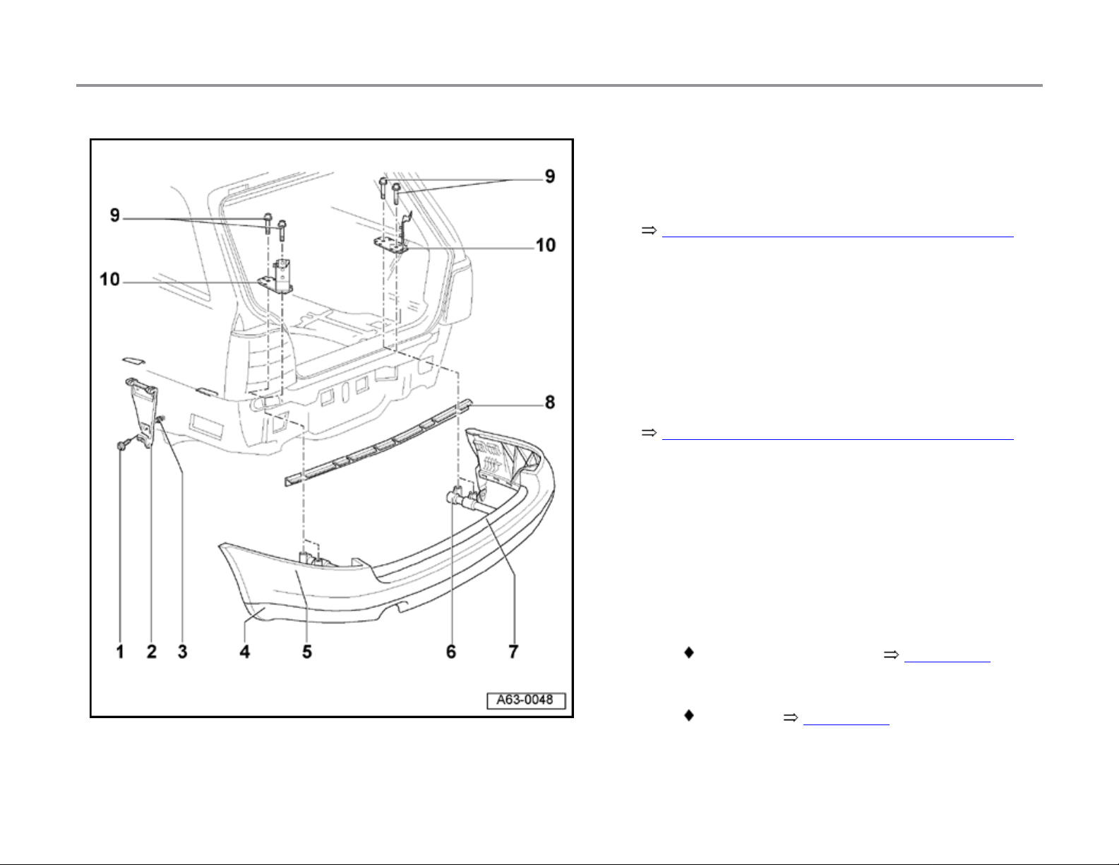
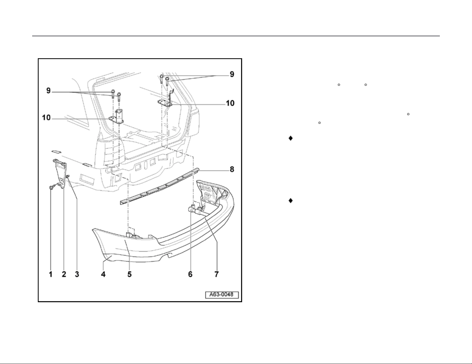
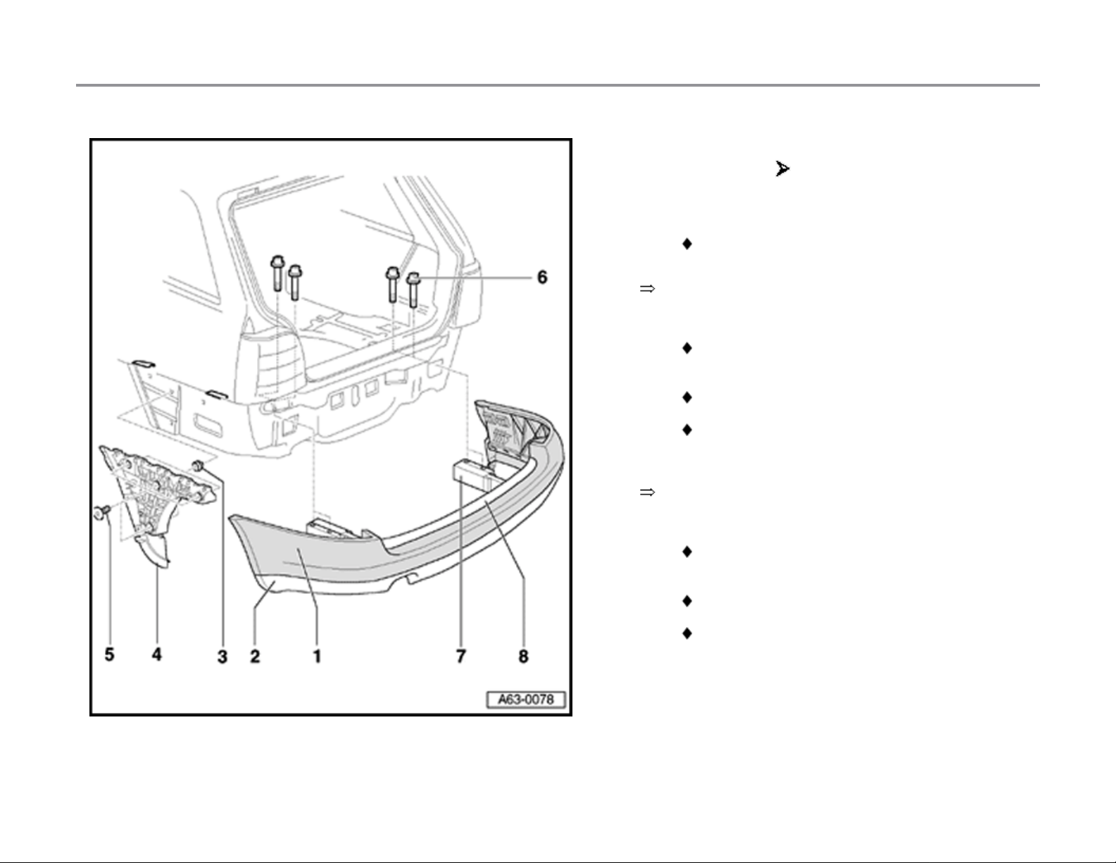
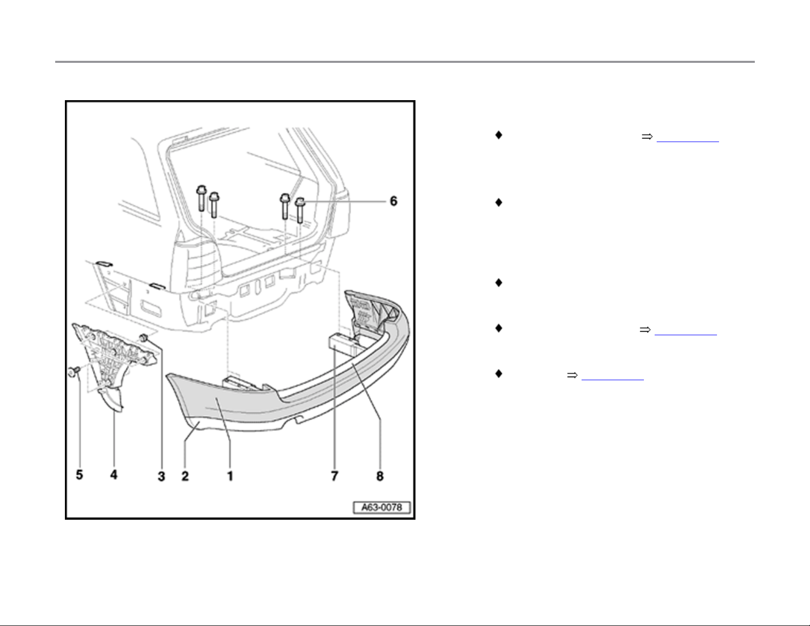
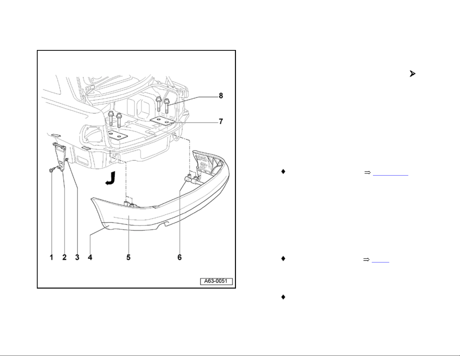
Rear bumper (Avant)
Rear bumper, removing, installing and
assembly overview ( VIN 8D XA 200 000)
1 - Metal bolt
2 - Bracket
3 - Clip
4 - Spoiler
- To remove, remove metal bolts -1- and
take off bracket.
Removing and installing page 63-10
11/20/2002http://127.0.0.1:8080/audi/servlet/Display?action=Goto&type=repair&id=AUDI.B5.BD01.63.4
Page 24
Page 2 of 8Rear bumper (Avant
)
63-17
5 - Bumper
- Before removing, remove rear panel trim.
Repair Manual, Body-Interior, Repair Group 70
- Remove tailgate seal in area of loading
edge/side pan els.
- Fold luggage compartment cover
forward.
- Remove tie-downs left an d right at side
trim and unclip rear side trim.
Repair Manual, Body-Interior, Repair Group 70
- Carefully pull side trim at left and right
towards vehicle interior.
- Remove combination bolts -9-.
- Unclip bumper from bracket -2- in
direction of arrow and pull off towards
rear.
6 - Bracket
Removing from bumper page 63-19
7 - Cover strip
Removing page 63-19
11/20/2002http://127.0.0.1:8080/audi/servlet/Display?action=Goto&type=repair&id=AUDI.B5.BD01.63.4
Page 25
Page 3 of 8Rear bumper (Avant
)
63-18
8 - Support
9 - Combination bolt
10 - Console
- To remove, heat body with heat gun to
approx. 40 C (104 F) and pull off
support.
- To attach, heat body in adhesion area
with hot air injector to approx. 40 C
(104 F).
Adhesion surface must be free of dust and
grease
- Pull off protective foil and press on
support using special tool 3356
(application roller).
23 Nm (17 ft lb)
11/20/2002http://127.0.0.1:8080/audi/servlet/Display?action=Goto&type=repair&id=AUDI.B5.BD01.63.4
Page 26
Page 4 of 8Rear bumper (Avant
)
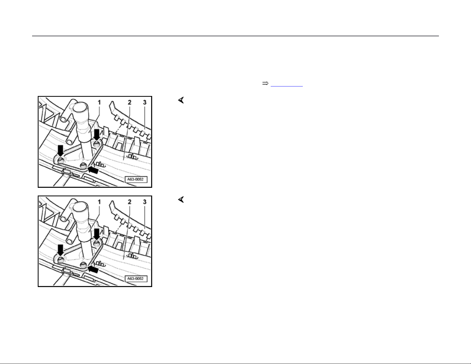
63-19
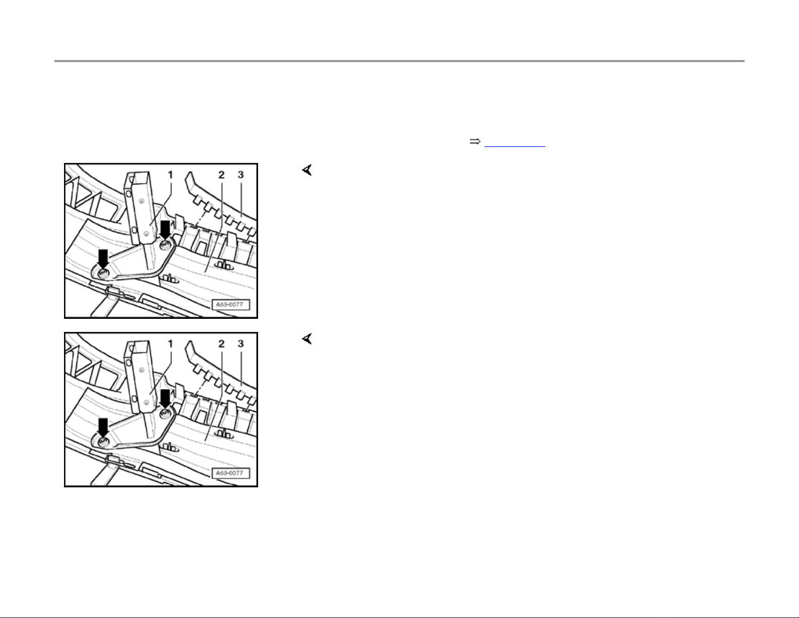
Bumper cover strip, removing
- Remove bumper page 63-1 .
- Release locking mechanism and unclip cover strip -3- from bumper -2-.
Removing bracket from bumper
- Remove bolts (arrows) and take bracket -1- out of bumper -2-.
Tightening torque: 23 Nm (17 ft lb)
11/20/2002http://127.0.0.1:8080/audi/servlet/Display?action=Goto&type=repair&id=AUDI.B5.BD01.63.4
Page 27
Page 5 of 8Rear bumper (Avant
)
63-20
Rear bumper, removing and installing (VIN
8D XA 200 001 )
1 - Bumper
Before removing, remove rear panel trim.
Repair Manual, Body-Exterior, Repair Group 70,
trim pieces.
Remove rear lid seal around loading edge
and sides.
Fold luggage compartment cover forward.
Remove tie-downs left and right at side trim
and unclip rear side trim.
Repair Manual, Body-Exterior, Repair Group 70,
trim pieces.
Carefully pull side trim at left and right
toward vehicle interior.
Remove screw w/washer assembly -6-.
Unclip bumper from bracket -4- and
remove toward rear.
11/20/2002http://127.0.0.1:8080/audi/servlet/Display?action=Goto&type=repair&id=AUDI.B5.BD01.63.4
Page 28
Page 6 of 8Rear bumper (Avant
)
63-21
2 - Spoiler
Removing and installing page 63-10 .
3 - Clip
4 - Bracket
To remove, remove metal bo lts -5- and
remove bracket -2-.
5 - Metal bolt
6 - Screw w/washer assembly
23 Nm
7 - Bracket
Removing from bumper page 63-22 .
8 - Cover strip
Removing page 63-22 .
11/20/2002http://127.0.0.1:8080/audi/servlet/Display?action=Goto&type=repair&id=AUDI.B5.BD01.63.4
Page 29
Page 7 of 8Rear bumper (Avant
)
63-22
Bumper cover strip, removing
- Remove rear bumper page 63-20 .
- Release locking mechanism and unclip cover strip -3- from bumper -2-.
- for removing impact absorber.
Fig. 1 Removing bracket from bumper
- Remove bolts (arrows) and take bracket -1- out of bumper -2-.
- Installation tightening torque 23 Nm.
11/20/2002http://127.0.0.1:8080/audi/servlet/Display?action=Goto&type=repair&id=AUDI.B5.BD01.63.4
Page 30
Page 8 of 8Rear bumper (Avant
)
63-23
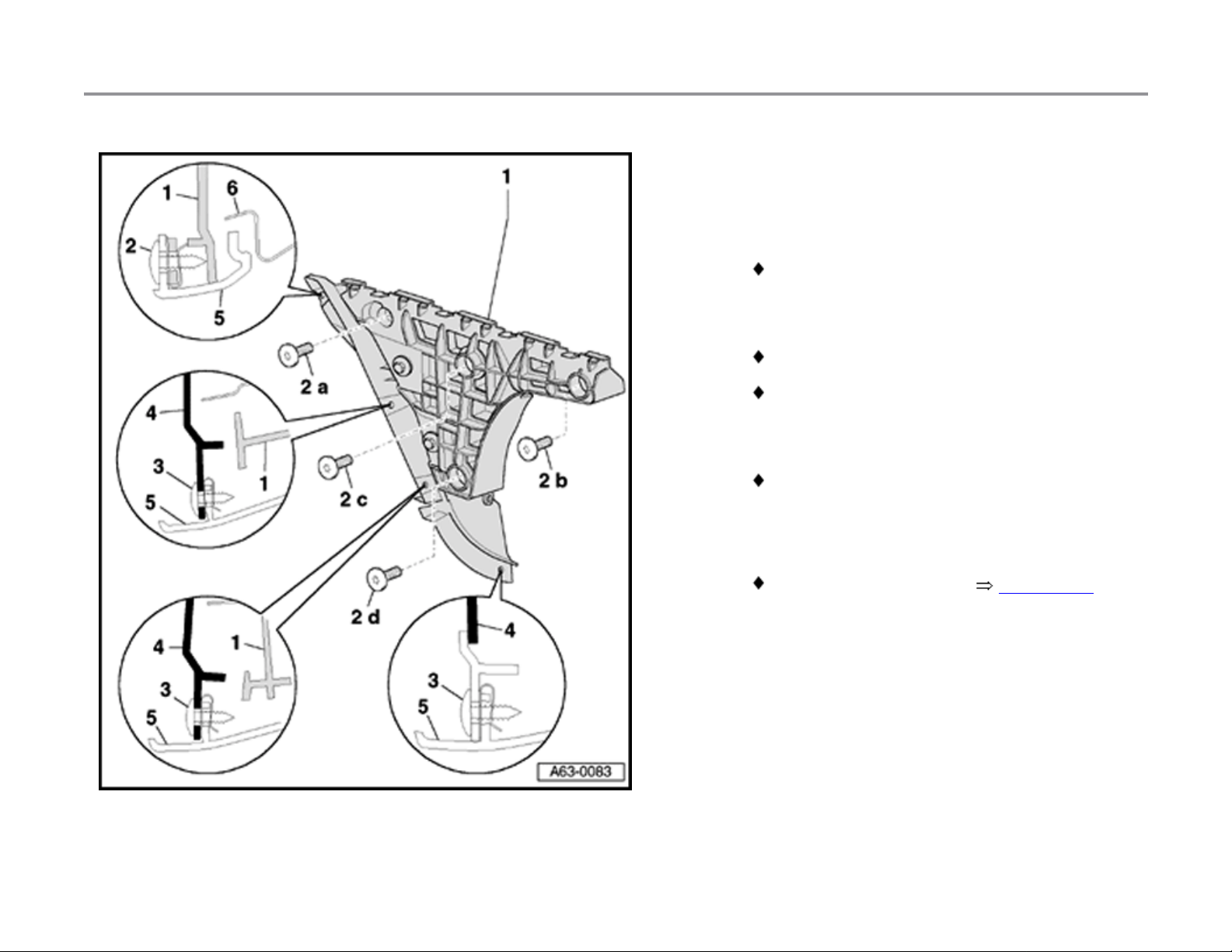
Bracket for rear bumper, removing and
installing
1 - Bracket for rear bumper
The bracket has two parts. The front half
can be shifted to adjust the length.
2 - Combination bolts
1.5 Nm.
Tighten bolts in sequence -a-, -b-, -c- then -
d-.
3 - Metal bolt
1.5 Nm.
4 - Wheelhousing liner, rear
5 - Rear bumper
Removing and installing page 63-20 .
11/20/2002http://127.0.0.1:8080/audi/servlet/Display?action=Goto&type=repair&id=AUDI.B5.BD01.63.4
Page 31
Page 1 of 5Rear bumper (Sedan
)
63-11
Rear bumper (Sedan)
Rear bumper, removing and installing (
VIN 8D XA 200 000)
1 - Metal bolt
2 - Bracket
3 - Clip
4 - Spoiler
5 - Bumper
6 - Impact absorber
- To remove, remove metal bolts -1- and
take off bracket.
Removing and installing page 63-10
- To remove, unscrew combination bolts 8-.
- Unclip bumper from bracket -2- in
direction of arrow and pull off towards
rear.
Removing from bumper Fig. 1
7 - Strengthening plate
8 - Combination bolt
23 Nm (17 ft lb)
11/20/2002http://127.0.0.1:8080/audi/servlet/Display?action=Goto&type=repair&id=AUDI.B5.BD01.63.3
Page 32

Page 2 of 5Rear bumper (Sedan
)
63-12
Fig. 1 Removing impact absorber from bumper
- Remove bolts (arrows) and take impact absorber -1- out of bumper -2-.
- When installing, tighten to 23 Nm (17 ft lb).
11/20/2002http://127.0.0.1:8080/audi/servlet/Display?action=Goto&type=repair&id=AUDI.B5.BD01.63.3
Page 33

Page 3 of 5Rear bumper (Sedan
)
63-13
Rear bumper, removing and installing (VIN
8D XA 200 001 )
1 - Bumper
To remove, remove combinat ion bolts -6-.
For S4 models, an additional bolt must be
installed at the wheelh ousi n g liner Fig.
1 .
Unclip bumper from bracket -4- and
remove toward rear.
2 - Spoiler
Removing and installing page 63-10 .
3 - Metal bolt
1.5 Nm.
4 - Bracket for rear bumper
The bracket has two parts. The front half
can be shifted to adjust the length.
11/20/2002http://127.0.0.1:8080/audi/servlet/Display?action=Goto&type=repair&id=AUDI.B5.BD01.63.3
Page 34

Page 4 of 5Rear bumper (Sedan
)
63-14
5 - Clip
To install, press into fender.
6 - Combination bolt
23 Nm
7 - Impact absorber
Removing from bumper Fig. 2 .
11/20/2002http://127.0.0.1:8080/audi/servlet/Display?action=Goto&type=repair&id=AUDI.B5.BD01.63.3
Page 35

Page 5 of 5Rear bumper (Sedan
)
63-15
Fig. 1 Additional mount for S4
- Remove bolt -2 from wheelhousing liner before disassembling bumper
-1-.
- Clip -4- is clipped onto wheelhousing liner -3-.
Fig. 2 Removing impact absorber from bumper
- Remove bolts (arrows) and take impact absorber -1- out of bumper -2-.
- When installing, tighten to 23 Nm.
11/20/2002http://127.0.0.1:8080/audi/servlet/Display?action=Goto&type=repair&id=AUDI.B5.BD01.63.3
Page 36

Page 1 of 14Rear lid ([micro] m.y. 1999 VIN 8D XA 200 000
)
55-12
Rear lid ( m.y. 1999 VIN 8D XA
200 000)
Rear lid and rear lid lock, removing,
installing and adjusting
1 - Stop buffer (2x)
Adjusting:
- Loosen bolt -11- and detach stop buffer.
- Carefully open rear lid -3-.
- Tighten bolt -11- finger-tight (it must still
be possible to move stop buffer).
- Carefully close rear lid until lid is flush
with rear side panels.
- Pull stop buffer -1- out two catches (1
mm preload) and tighten bolt -2- to 6 Nm
0.5 Nm (53 in. lb 4 in. lb).
11/20/2002http://127.0.0.1:8080/audi/servlet/Display?action=Goto&type=repair&id=AUDI.B5.BD01.55.2
Page 37

Page 2 of 14Rear lid ([micro] m.y. 1999 VIN 8D XA 200 000
)
55-13
2 - Rear lid
Removing:
- Remove warning triangle and holder
page 55-21 .
- Remove rear li d lining.
- Disconnect and unclip electrical wiring
harness connectors.
- Unclip vacu um line for cen tral locking
system.
Second person is needed to remove lid
- Remove nuts for rear lid hinges page
55-16 .
Installing:
- Install in reverse order of removal.
Adjusting:
- Use rear lid hinges to center and adjust
height of rear lid page 55-17 .
- Adjust stop buffers -1-.
- Adjust striker plate -5-.
3 - Rear lid lock
- Center lid according to panel gap
dimensions page 55-20 .
- Unclip operating rod -9-.
11/20/2002http://127.0.0.1:8080/audi/servlet/Display?action=Goto&type=repair&id=AUDI.B5.BD01.55.2
Page 38

- Unscrew nuts -8-.
)
Page 3 of 14Rear lid ([micro] m.y. 1999 VIN 8D XA 200 000
11/20/2002http://127.0.0.1:8080/audi/servlet/Display?action=Goto&type=repair&id=AUDI.B5.BD01.55.2
Page 39

Page 4 of 14Rear lid ([micro] m.y. 1999 VIN 8D XA 200 000
)
55-14
4 - Locking cylinder
- Remove warning triangle and holder
page 55-21 .
- Remove rear li d lining.
- Disconnect vacuum line for central
locking system.
- Disconnect harness connectors.
- Unclip operating rod -9-.
- Remove bolts -7-.
5 - Striker plate
- Unscrew nuts -6-.
Adjusting:
- Tighten nuts -6- finger-tight (it must still
be possible to move striker plate).
- Carefully close rear lid until lid is flush
with rear side panels.
- Carefully open lid and tighten nuts -6-.
6 - Hex nut
8 Nm (71 in. lb)
7 - Hex nut
8 Nm (71 in. lb)
8 - Hex nut
11/20/2002http://127.0.0.1:8080/audi/servlet/Display?action=Goto&type=repair&id=AUDI.B5.BD01.55.2
Page 40

6 Nm (53 in. lb)
)
Page 5 of 14Rear lid ([micro] m.y. 1999 VIN 8D XA 200 000
9 - Operating rod
11/20/2002http://127.0.0.1:8080/audi/servlet/Display?action=Goto&type=repair&id=AUDI.B5.BD01.55.2
Page 41

Page 6 of 14Rear lid ([micro] m.y. 1999 VIN 8D XA 200 000
)
55-15
10 - Retaining clip
11 - Hex bolt
6 Nm (53 in. lb)
11/20/2002http://127.0.0.1:8080/audi/servlet/Display?action=Goto&type=repair&id=AUDI.B5.BD01.55.2
Page 42
Page 7 of 14Rear lid ([micro] m.y. 1999 VIN 8D XA 200 000
)
55-16
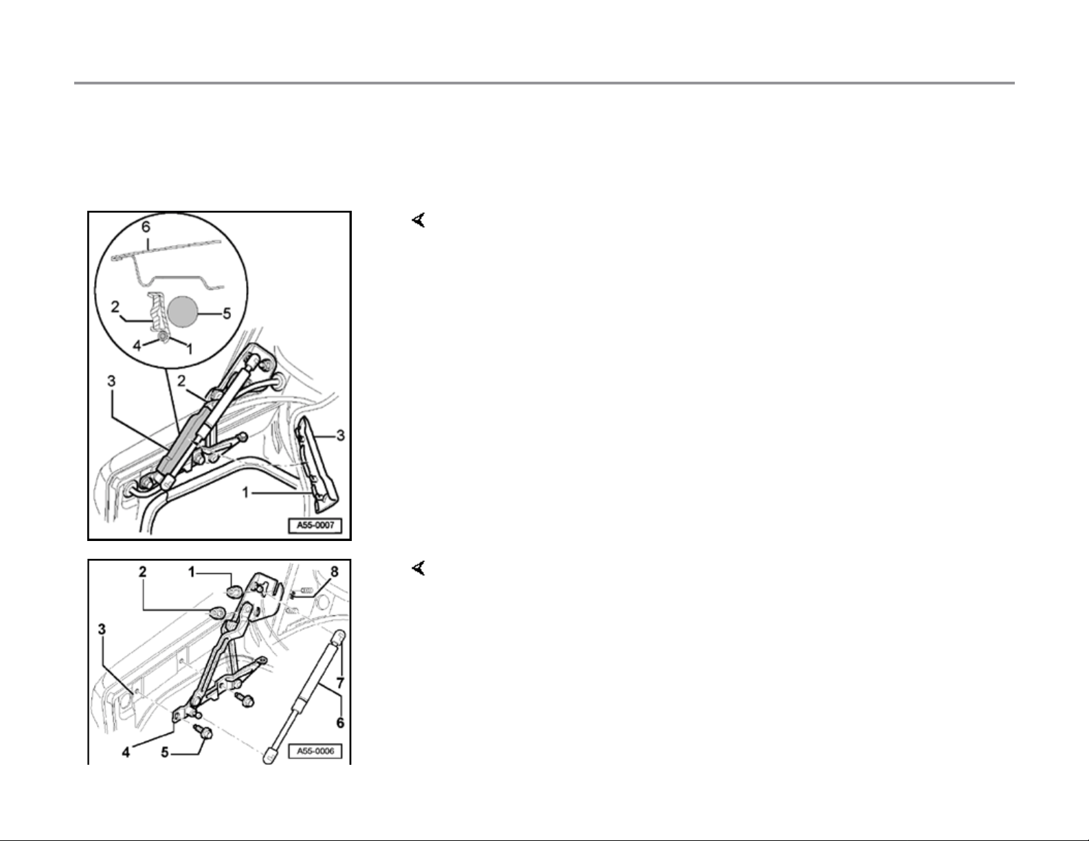
Rear lid hinge, removing and installing
Rear lid hinge cover
- Insert wiring and tubing for central locking system -4- into lower recess
of cable guide at cover -1-.
- From below, attach cover -3- for rear lid hinge between gas-filled strut 5- and hinge lever, and clip onto hinge lever -2- at top so it engages
audibly.
Removing and installing rear lid hinge
- Loosen nuts -1- at top on left and right.
Tightening torque: 21 Nm (15 ft lb)
- Remove nuts -2- at bottom on left and right.
Tightening torque: 21 Nm (15 ft lb)
- Prop up or se cure lid in open position.
11/20/2002http://127.0.0.1:8080/audi/servlet/Display?action=Goto&type=repair&id=AUDI.B5.BD01.55.2
Page 43

Page 8 of 14Rear lid ([micro] m.y. 1999 VIN 8D XA 200 000
)
55-17
- Remove bolts -5- (2x).
Tightening torque: 21 Nm (15 ft lb)
- Lift lid slightly and remove hinge -4-.
Note:
For easier adjustment of the rear lid hinge, use graduations -3- and -8marked on the hinge and the rear lid.
Removing and installing gas-filled strut
- Using screwdriver, push back retaining springs -7- slightly at both ends
of gas-filled strut and clip or unclip gas-filled strut as desired.
Note:
When removing or installing the gas-filled strut, push back the opened
rear lid slightly beyond its normal position, being careful not to damage
components.
Installing
- Clip in gas-filled strut at bottom first, then at top.
- Install with tube end of strut at rear lid.
11/20/2002http://127.0.0.1:8080/audi/servlet/Display?action=Goto&type=repair&id=AUDI.B5.BD01.55.2
Page 44
Page 9 of 14Rear lid ([micro] m.y. 1999 VIN 8D XA 200 000
)
55-18
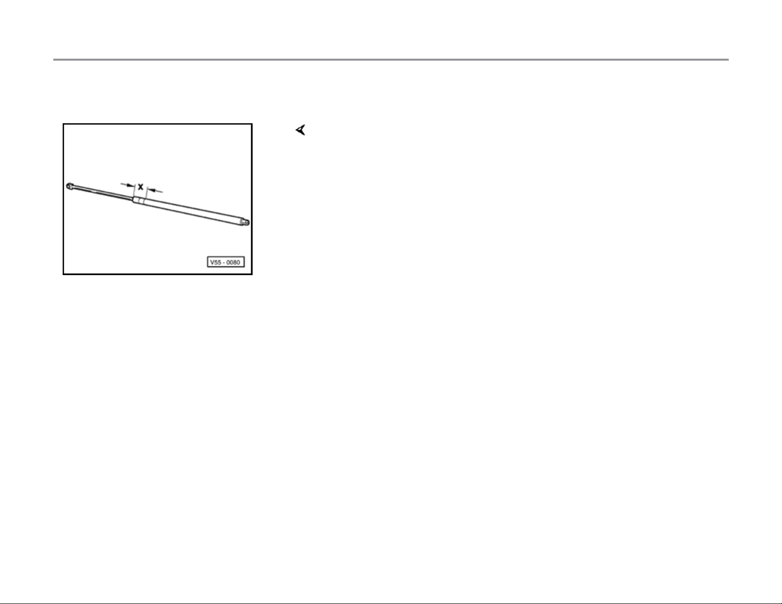
Releasing gas from strut
- Clamp gas-filled strut in vice area -x-.
Dimension -x- = 50 mm (2 in.)
- Using saw, cut into cylindrical part of strut at point within first third of
cylinder's length (measured from piston rod end of cylinder).
WARNING!
Clamp only in the area shown; otherwise there is a risk of an
accident!
Note:
Always wear eye protection when performing this procedure. Cover the
sawing area with a clean rag to contain any esc aping fluid.
11/20/2002http://127.0.0.1:8080/audi/servlet/Display?action=Goto&type=repair&id=AUDI.B5.BD01.55.2
Page 45

Page 10 of 14Rear lid ([micro] m.y. 1999 VIN 8D XA 200 000
)
55-19
Rear lid seal, installing
The butt joint -A- of the rear lid seal must be aligned with the ball socket of
left hinge.
11/20/2002http://127.0.0.1:8080/audi/servlet/Display?action=Goto&type=repair&id=AUDI.B5.BD01.55.2
Page 46

Page 11 of 14Rear lid ([micro] m.y. 1999 VIN 8D XA 200 000
)
55-20
Removing and installing handle mechanism
for rear lid
- Remove bolts -1- (2x).
Tightening torque: 2.5 Nm (22 in. lb)
- Attachment point -A-; remove nuts (2x) for lock cy linder on inside of lid.
Tightening torque: 6 Nm (53 in. lb)
- Pull handle mechanism -3- out enough that harness connectors for
both license plate lights can be disconnected.
- Remove handle mechanism.
- Install nuts -2- (2x) using special tool VAG1618A.
Panel gap dimensions
-a- 3.0 mm
11/20/2002http://127.0.0.1:8080/audi/servlet/Display?action=Goto&type=repair&id=AUDI.B5.BD01.55.2
Page 47

Page 12 of 14Rear lid ([micro] m.y. 1999 VIN 8D XA 200 000
)
55-21
Removing and installing holder for warning
triangle
- Remove warning triangle.
- Remove bolts -2- (2x).
Tightening torque: 2 Nm
1 - Holder
3 - Expanding clips (2x)
11/20/2002http://127.0.0.1:8080/audi/servlet/Display?action=Goto&type=repair&id=AUDI.B5.BD01.55.2
Page 48

Page 13 of 14Rear lid ([micro] m.y. 1999 VIN 8D XA 200 000
)
55-22
Rear lid lock actuator, removing and
installing
Removing
- Remove lock cylinder page 55-14 .
- Push out retaining pins -3- (2x).
- Push tab -4- back and disconnect.
- Remove rear lid lock a c tuator -1-.
Installing
- Set lock cylinders in "open" position.
- Slide ridged plate -1- to left.
First ridge on plate -1- must snap into first groove on grooved segment
-2-.
11/20/2002http://127.0.0.1:8080/audi/servlet/Display?action=Goto&type=repair&id=AUDI.B5.BD01.55.2
Page 49

Page 14 of 14Rear lid ([micro] m.y. 1999 VIN 8D XA 200 000
)
55-23
Rear lid microswitch, removing
- Remove lock cylinder page 55-14 .
- Disengage microswitch -1- in direction of arrow and carefully push out
using screwdriver.
Notes:
The lock cylinder cannot be adjusted for compatibility with other locks
using standard tools.
In order to maintain single key capability, the lock cylinder must be
ordered according to the lock number.
11/20/2002http://127.0.0.1:8080/audi/servlet/Display?action=Goto&type=repair&id=AUDI.B5.BD01.55.2
Page 50

Page 1 of 8Rear lid (m.y. 1999 VIN 8D XA 200 001 [micro]
)
55-24
Rear lid (m.y. 1999 VIN 8D XA
200 001 )
Grip piece, removing and installi ng
1 - Hex bolt
8 Nm
2 - Hex nut
8 Nm
3 - Tailgate
4 - Seal
11/20/2002http://127.0.0.1:8080/audi/servlet/Display?action=Goto&type=repair&id=AUDI.B5.BD01.55.3
Page 51

Page 2 of 8Rear lid (m.y. 1999 VIN 8D XA 200 001 [micro]
)
55-25
5 - Grip piece
Removing:
- Before removal , remove tailgate trim.
Repair Manual, Body-Interior, Repair Group 70
- Disconnect electrical harness connector
for license plate lights and switch for rear
lid release.
- Remove hex bolts -1- and hex nuts -3-.
Locking system is removed from rear lid via
interior of luggage compartment
- Pull grip piece out of rear lid.
Installing:
- First tighten both hex nuts -2- to 8 Nm.
- Then secure locking system using hex
bolts -1- and tighten bolts to 8 Nm.
- Re-connect electrical connection.
11/20/2002http://127.0.0.1:8080/audi/servlet/Display?action=Goto&type=repair&id=AUDI.B5.BD01.55.3
Page 52

Page 3 of 8Rear lid (m.y. 1999 VIN 8D XA 200 001 [micro]
)
55-26
Rear lid microswitch, removing and
installing
1 - Grip piece
2 - License plate lights
3 - Sealing washer
4 - Rear lid microswitch
- Disconnect electrical connectors.
- Remove grip piece.
5 - Seal
- Release locking mechanism (arrow) and
remove microswitch.
Adhesion surface must be free of dust and
grease
Self adhesive; remove protective foil before
application and press seal on in center
11/20/2002http://127.0.0.1:8080/audi/servlet/Display?action=Goto&type=repair&id=AUDI.B5.BD01.55.3
Page 53

Page 4 of 8Rear lid (m.y. 1999 VIN 8D XA 200 001 [micro]
)
55-27
Tailgate lock, removing and installing
1 - Rear lid lock actuator
Before removing, first disengage operating
rod -2- from rear lid lock Fig. 6
- Disconnect electrical harness connector.
- Remove Torx bo lts -8-.
2 - Operating rod
Disengage and engage in rear lid lock
Fig. 6
3 - Tailgate lock
Removing:
- Disengage ope ra ti ng ro d -2- and
connecting rode -5- from rear lid lock.
- Disconnect electrical harness connector.
- Remove hex nuts -4- and take out rear
lid lock.
11/20/2002http://127.0.0.1:8080/audi/servlet/Display?action=Goto&type=repair&id=AUDI.B5.BD01.55.3
Page 54

Page 5 of 8Rear lid (m.y. 1999 VIN 8D XA 200 001 [micro]
)
55-28
4 - Hex nut
8 Nm
5 - Operating rod
Unclip and clip in rear lid lock Fig. 6
6 - Hex nut
8 Nm
7 - Lock mechanism
Removing page 55-30
8 - Torx screw
2.5 Nm
11/20/2002http://127.0.0.1:8080/audi/servlet/Display?action=Goto&type=repair&id=AUDI.B5.BD01.55.3
Page 55

Page 6 of 8Rear lid (m.y. 1999 VIN 8D XA 200 001 [micro]
)
55-29
Fig. 6 Disengaging and engaging operating and connecting rods
- Swing hinge arm -6- in direction of arrow -A- and pull out connecting
rod -4-.
- Swing hinge arm -3- in direction of arrow -B- and pull out connecting
rod -5-.
- To remove rear lid lock -1- remove hex bolts -2-.
11/20/2002http://127.0.0.1:8080/audi/servlet/Display?action=Goto&type=repair&id=AUDI.B5.BD01.55.3
Page 56

Page 7 of 8Rear lid (m.y. 1999 VIN 8D XA 200 001 [micro]
)
55-30
Tailgate lock system, removing and
installing
- Remove tailgate trim.
- Disengage connecting rod to rear lid lock.
- Disconnect harness connectors -3- from microswitch and -4- from
locking system.
- Remove hex bolts -2- and locking system -1- from rear lid.
11/20/2002http://127.0.0.1:8080/audi/servlet/Display?action=Goto&type=repair&id=AUDI.B5.BD01.55.3
Page 57

Page 8 of 8Rear lid (m.y. 1999 VIN 8D XA 200 001 [micro]
)
55-31
Tailgate gap, dimensions
Letter Actual gap dimension (mm) Parrallelism (mm)
A 4.7 + 1.5
B 2.9 + 1 1
C 3.3 + 1
D 4.9 + 1 1
E 3.5 + 1 0.5
F 2.5 + 0.5 0.5
G 1.5 + 0.5 0.2
H
I
J
K
2.5 0.1
3.3 0.1
3.3 0.2
3.0 0.4
11/20/2002http://127.0.0.1:8080/audi/servlet/Display?action=Goto&type=repair&id=AUDI.B5.BD01.55.3
Page 58

Page 1 of 1Rear wheelhousing liner, removing and installin
g
66-32
Rear wheelhousing liner,
removing and ins t alling
1 - Rear wheelhousing liner (Front Wheel
Drive vehicles)
Rear wheel removed.
2 - Rear wheelhousing liner (Quattro)
3 - Phillips-head screw
4 - Clip
- Remove Phillips-head screws -3- at top
(5x) and bottom (4x).
- Remove wheelhousing liner from si de
panel above suspension strut mount.
Removing and installing same as for Front
Wheel Drive.
2.5 Nm
11/20/2002http://127.0.0.1:8080/audi/servlet/Display?action=Goto&type=repair&id=AUDI.B5.BD01.66.15
Page 59

Page 1 of 6Rocker panel cover, removing and installing (S4
)
66-22
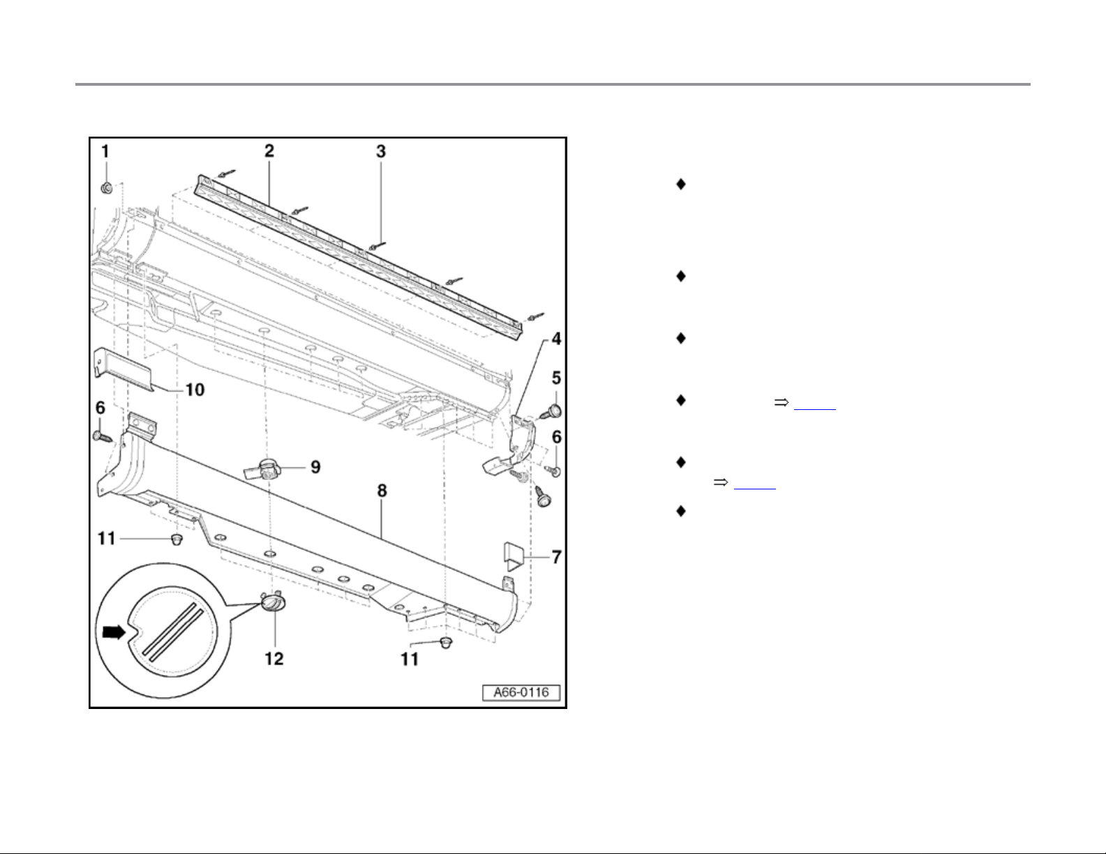
Rocker panel cover, removing
and installing (S4)
1 - Hex nut
1 Nm
2 - Retaining strip
Adhesive surfaces must be free of dust and
grease before pressing on retaining strip.
Self-adhesive, remove protective foil just
prior to assembly.
- Use hot air gun to warm retaining strip to
approx. 40 C (max 50 C) before
assembly.
- Center retaining strip using one hollow
rivet at the front and one at the rear.
- Press complete surface of retaining strip
securely into adhesive areas at sill.
- Rivet retaining strip to sill, starting at
front and moving toward rear.
11/20/2002http://127.0.0.1:8080/audi/servlet/Display?action=Goto&type=repair&id=AUDI.B5.BD01.66.11
Page 60
Page 2 of 6Rocker panel cover, removing and installing (S4
)
66-23
3 - Hollow rivet
5x.
4 - Bracket
5 - Collar screw
1.5 Nm.
6 - Phillips-head screw
1.5 Nm.
7 - Rear trim piece
Removing Fig. 2 .
8 - Rocker panel cover for sill
Before removing, remove rear trim piece 7- Fig. 2 .
Remove front end piece -10-.
- Remove Phillip s-head screws -6- at front
and rear.
- Disengage twist locks -12- and remove.
- Remove cap nu ts -11-.
11/20/2002http://127.0.0.1:8080/audi/servlet/Display?action=Goto&type=repair&id=AUDI.B5.BD01.66.11
Page 61

Page 3 of 6Rocker panel cover, removing and installing (S4
)
66-24
- Remove bolts for securing wheelhousing liner
near hex nut s -1-.
- Press wheelhousing liner to side and remove
hex nuts -1-.
- Bolts for securing the EVAP canister must also
be removed on right-hand side.
- Pull rocker arm cover slightly forward out of
bracket -4- and remove from sill.
9 - Mount for twist lock
Tab on mount must face vehicle interior.
11/20/2002http://127.0.0.1:8080/audi/servlet/Display?action=Goto&type=repair&id=AUDI.B5.BD01.66.11
Page 62

Page 4 of 6Rocker panel cover, removing and installing (S4
)
66-25
10 - Front end piece
Removing Fig. 1 .
11 - Cap nut
1.5 Nm.
12 - Twist lock
Notch (arrow) must face front of vehicle.
11/20/2002http://127.0.0.1:8080/audi/servlet/Display?action=Goto&type=repair&id=AUDI.B5.BD01.66.11
Page 63

Page 5 of 6Rocker panel cover, removing and installing (S4
)
66-26
Fig. 1 Removing and installing front end piece
- Remove front wheel.
- Drill rivet heads off hollow rivets -3- an knock rivet shaft through.
- Remove wheelhousing liner bolts around front end piece.
- Press wheelhousing liner to side and remove hex nut -2-.
- Remove front end piece -1- from fender toward side.
11/20/2002http://127.0.0.1:8080/audi/servlet/Display?action=Goto&type=repair&id=AUDI.B5.BD01.66.11
Page 64

Page 6 of 6Rocker panel cover, removing and installing (S4
)
66-27
Fig. 2 Removing and installing rear trim piece
- Drill rivet head off hollow rivet -2- an knock rivet shaft through.
- Push pin through expanding clip and remove expanding clip from trim
piece.
- Pin is required when reinstalling expanding clip.
- Pull trim piece up and out of bracket first and then remove.
- For further removal of rocker panel cover, remove Phillips-head screws
(arrows).
11/20/2002http://127.0.0.1:8080/audi/servlet/Display?action=Goto&type=repair&id=AUDI.B5.BD01.66.11
Page 65

Page 1 of 1Spoiler, removing and installin
g
63-10
Spoiler, removing and installing
1 - Bumper
Remove before detaching spoiler
2 - Spoiler
3 - Expanding clip
- To remove, take out expanding clips -3on both sides.
- Unclip retaining tabs (arrow) from spoiler
and remove spoiler from bumper.
- To remove, pull pins out and pry out
expanding clips.
11/20/2002http://127.0.0.1:8080/audi/servlet/Display?action=Goto&type=repair&id=AUDI.B5.BD01.63.2
Page 66

Page 1 of 18Tailgate (Avant), ([micro] m.y. 1999 VIN 8D XA 200 000
)
55-32
Tailgate (Avant), ( m.y. 1999
VIN 8D XA 200 000)
Repair Manual, Body-Interior, Repair Group
Tailgate, removing and installing
- Remove tailgate trim.
70
- Disconnect or remove harness connectors and
hoses (i.e. for central locking and rear window
washer system).
- Prop up and secure tailgate in open positio n.
- Using screwdriver, lift retaining spring -3- as shown and remove gasfilled strut -1- from upp er ball stud -2-.
Note:
Following complete removal of gas-filled strut, check for correct
positioning during installation.
Sound insulation components must be installed on the body side.
- To install, press gas-filled strut onto ball studs so that it engages in
position.
11/20/2002http://127.0.0.1:8080/audi/servlet/Display?action=Goto&type=repair&id=AUDI.B5.BD01.55.4
Page 67

Ball stud tightening torque: 15 Nm -1 Nm
)
Page 2 of 18Tailgate (Avant), ([micro] m.y. 1999 VIN 8D XA 200 000
11/20/2002http://127.0.0.1:8080/audi/servlet/Display?action=Goto&type=repair&id=AUDI.B5.BD01.55.4
Page 68

Page 3 of 18Tailgate (Avant), ([micro] m.y. 1999 VIN 8D XA 200 000
)
55-33
- Remove hex bolt -1 - (2x) from tailgate -6-.
Tightening torque: 21 Nm (15 ft lb)
11/20/2002http://127.0.0.1:8080/audi/servlet/Display?action=Goto&type=repair&id=AUDI.B5.BD01.55.4
Page 69

Page 4 of 18Tailgate (Avant), ([micro] m.y. 1999 VIN 8D XA 200 000
)
55-34
Tailgate, adjusting
Note:
Before installing a new tailgate the gas-filled
struts must be installed.
- Loosely attach striker -1- with nuts -2-.
- Loosely attach lower stop -1- (on trim of rear hatch) using hex bolt -2-.
11/20/2002http://127.0.0.1:8080/audi/servlet/Display?action=Goto&type=repair&id=AUDI.B5.BD01.55.4
Page 70

Page 5 of 18Tailgate (Avant), ([micro] m.y. 1999 VIN 8D XA 200 000
)
55-35
- Screw upper stop -2- in fully.
- Close rear hatch to appropriate position (flush).
Rear lock and striker must engage.
- Open rear hatch and tighten mounting nut for striker to 8 Nm (71 in. lb).
- Install clay onto upper stop.
- Close and open tailgate.
- Determine thickness of clay and adjust stop accordingly.
- Unscrew stop another 1.5 to 2 rotations.
Note:
Two (2) rotations represent a preload of 2.5 mm and a vertical shift of 0.8
mm at point -C- page 55-41 .
- Check shutting comfort and gap dimensions.
11/20/2002http://127.0.0.1:8080/audi/servlet/Display?action=Goto&type=repair&id=AUDI.B5.BD01.55.4
Page 71

Page 6 of 18Tailgate (Avant), ([micro] m.y. 1999 VIN 8D XA 200 000
)
55-36
- Screw stop -1- into lock nut.
Tightening torque: 21 Nm (15 ft lb)
- Push cover on stop up toward tailgate surface (arrow).
2 - Protective cap
- Loosen hex bolt -2- and pull lower stop -1- out slightly.
- Tighten hex bolt -2- slightly and close rear hatch.
- Using sensor gauge, set stop -1- from inside at 1 mm clearance to
tailgate trim.
11/20/2002http://127.0.0.1:8080/audi/servlet/Display?action=Goto&type=repair&id=AUDI.B5.BD01.55.4
Page 72

Page 7 of 18Tailgate (Avant), ([micro] m.y. 1999 VIN 8D XA 200 000
)
55-37
CAUTION!
Stop buffers must not make contact with rear
lid trim when rear lid is closed.
- Open hatch and tighten hex bolt -2- for stop to 8 Nm (71 in. lb).
- Check gap dimensions page 55-41 .
Removing and installing gas-filled strut
- Lift retaining spring on gas-filled st rut -1- and remove strut from ball
stud.
- To install, press gas-filled strut onto ball stud.
11/20/2002http://127.0.0.1:8080/audi/servlet/Display?action=Goto&type=repair&id=AUDI.B5.BD01.55.4
Page 73

Page 8 of 18Tailgate (Avant), ([micro] m.y. 1999 VIN 8D XA 200 000
)
55-38
Removing and installing ball stud
- Unscrew ball stud -1- and remove with seal.
- For installation, tighten to 14 Nm (10 ft lb).
11/20/2002http://127.0.0.1:8080/audi/servlet/Display?action=Goto&type=repair&id=AUDI.B5.BD01.55.4
Page 74

Page 9 of 18Tailgate (Avant), ([micro] m.y. 1999 VIN 8D XA 200 000
)
55-39
Rear lid hinge, removing and installing
- Remove screws -2- and cover -1- for hinge.
- To install, first center cover -1- in notches (arrow) in roof flange and
then tighten screws -2- to 2.5 Nm (22 in. lb).
- Remove rear ro of mo lding trim.
Repair Manual, Body-Interior, Repair Group 70
- Remove hex bolt -5 -.
- Remove hex bolt -1 -.
- Replace seal -3- during installation.
- Tighten hex bolt and bolt to 21 Nm (15 ft lb).
11/20/2002http://127.0.0.1:8080/audi/servlet/Display?action=Goto&type=repair&id=AUDI.B5.BD01.55.4
Page 75

Page 10 of 18Tailgate (Avant), ([micro] m.y. 1999 VIN 8D XA 200 000
)
55-40
Tailgate seal, removing and installing
- Open tailgate and remove seal.
- When installing, vulcanized butt joint (arrows) must be placed on body
side at height of ball stud.
- Press seal -1- onto body as shown.
11/20/2002http://127.0.0.1:8080/audi/servlet/Display?action=Goto&type=repair&id=AUDI.B5.BD01.55.4
Page 76
Page 11 of 18Tailgate (Avant), ([micro] m.y. 1999 VIN 8D XA 200 000
)
55-41
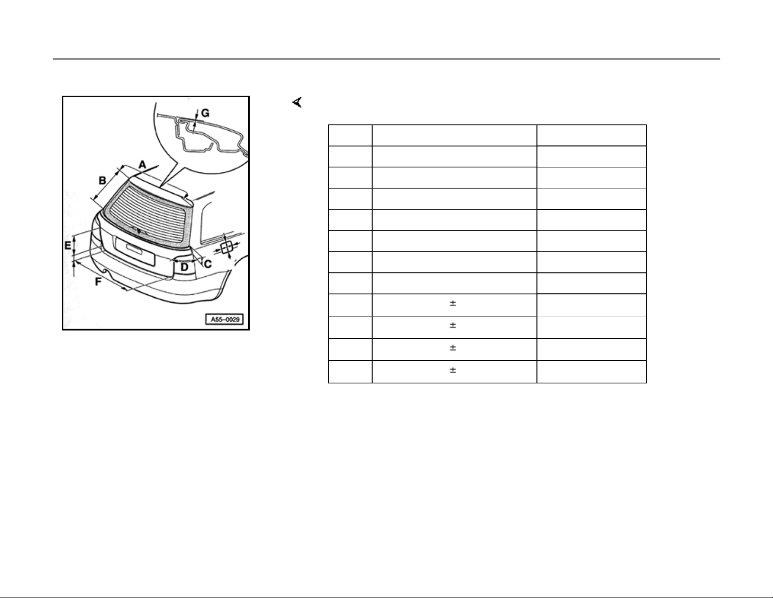
Gap dimensions, tailgate
Letter Actual gap dimension (mm) Parrallelism (mm)
-A- 4.0 +1 0.5
-B- 5.0 +1 1
-C- 4.0 +1 0.5
-D- 3.4 +1 0.5
-E- 3.4 +1 0.5
-F- 5.0+1
-G- 1.0
-H-
-I-
-J-
-K-
2.5 0.1
3.3 0.1
3.3 0.2
3.0 0.4
11/20/2002http://127.0.0.1:8080/audi/servlet/Display?action=Goto&type=repair&id=AUDI.B5.BD01.55.4
Page 77

Page 12 of 18Tailgate (Avant), ([micro] m.y. 1999 VIN 8D XA 200 000
)
55-42
Tailgate lock, removing and installing
1 - Tailgate lock
- To remove, swing out hinge arm -3- from
operating rod -4- and unho ok operati ng
rod from tailgate lock.
- Remove hex bolts -2- and tailgate lock.
2 - Hex nut
8 Nm (71 in. lb)
3 - Hinge arm
Must be swung over operating rod -4-
4 - Operating rod
5 - Hex nut
- To remove, first disengage fr om lock
system -6-.
8 Nm (71 in. lb)
6 - Lock system
Removing page 55-43
7 - Tailgate lock actuator
Removing page 55-44
11/20/2002http://127.0.0.1:8080/audi/servlet/Display?action=Goto&type=repair&id=AUDI.B5.BD01.55.4
Page 78

Page 13 of 18Tailgate (Avant), ([micro] m.y. 1999 VIN 8D XA 200 000
)
55-43
Tailgate lock system, removing and
installing
- Remove tailgate trim.
Repair Manual, Body-Interior, Repair Group 70
- Disengage lock system at plug for vacuum line -1- and remove from
lock actuator -2-.
- Unclip operating rod -3-.
- Disengage locating hooks on release handle and remove page 55-
47 .
- Remove hex bolts (arrow) and remove lock system from tailgate.
Hex bolt tightening torque: 8 Nm (71 in. lb)
11/20/2002http://127.0.0.1:8080/audi/servlet/Display?action=Goto&type=repair&id=AUDI.B5.BD01.55.4
Page 79

Page 14 of 18Tailgate (Avant), ([micro] m.y. 1999 VIN 8D XA 200 000
)
55-44
Lock actuator, removing and installing
- Push out clamping pins (arrow) and remove lock actuator -1- from lock
-2-.
- Clamping pins must be snapped into expanding clips again during
installation.
- Pry out using screwdriver if necessary.
Note:
Illustration shows component after removal.
11/20/2002http://127.0.0.1:8080/audi/servlet/Display?action=Goto&type=repair&id=AUDI.B5.BD01.55.4
Page 80

Page 15 of 18Tailgate (Avant), ([micro] m.y. 1999 VIN 8D XA 200 000
)
55-45
Grip piece, removing and installi ng
1 - Hex nut
8 Nm (71 in. lb)
2 - Bracket
Note:
- To remove, remove hex bolts -1- and
bolts -3-.
Part was discontinued shortly foll owi ng ser ies
launch.
3 - Hex bolt
8 Nm (71 in. lb)
4 - Tailgate
Removing and installing page 55-32
5 - Lock mechanism
- To remove, remove hex bolts -1-.
- Disengage locating hooks on release
handle ( Fig. 1 ) and remove.
- Remove lock mechanism.
11/20/2002http://127.0.0.1:8080/audi/servlet/Display?action=Goto&type=repair&id=AUDI.B5.BD01.55.4
Page 81

Page 16 of 18Tailgate (Avant), ([micro] m.y. 1999 VIN 8D XA 200 000
)
55-46
6 - Grip piece
- Before removal , remove tailgate trim.
Repair Manual, Body-Interior, Repair Group 70
- To remove, remove hex nuts -1- and
bolts -3-.
- Pull grip piece slightly out of tailgate and
disconnect harness connectors for
license plate l i ghts.
- To install, insert grip piece into tailgate
holes.
- Thread bracket -2- at lock mechanism
and attach to grip piece using external
securing screws.
11/20/2002http://127.0.0.1:8080/audi/servlet/Display?action=Goto&type=repair&id=AUDI.B5.BD01.55.4
Page 82

Page 17 of 18Tailgate (Avant), ([micro] m.y. 1999 VIN 8D XA 200 000
)
55-47
Fig. 1 Removing and installing lock unit
- Using screwdriver, press in and disengage securing hooks (arrow) on
inside of tailgate.
- Pull release handle -1- down and out of lock system -2- under grip
piece.
11/20/2002http://127.0.0.1:8080/audi/servlet/Display?action=Goto&type=repair&id=AUDI.B5.BD01.55.4
Page 83

Page 18 of 18Tailgate (Avant), ([micro] m.y. 1999 VIN 8D XA 200 000
)
55-48
Tailgate striker, removing and installing
- Before removing striker, ma rk its position using
soft pencil.
- To remove, unscrew hex nuts -2- and remove striker -1-.
- Position new striker according to markings and tighten hex nuts fingertight.
- Close tailgate until lock engages and tailgate is in flush position.
- Open tailgate and tighten hex nuts to 8 Nm (71 in. lb).
- Check for flushness and shutting comfort; adjust if necessary.
11/20/2002http://127.0.0.1:8080/audi/servlet/Display?action=Goto&type=repair&id=AUDI.B5.BD01.55.4
Page 84

Page 1 of 7Tailgate (Avant) (m.y. 1999 VIN 8D XA 200 001 [micro]
)
55-49
Tailgate (Avant) (m.y. 1999 VIN
8D XA 200 001 )
Grip piece, removing and installi ng
1 - Hex bolt
8 Nm
2 - Hex nut
8 Nm
3 - Tailgate
4 - Seal
11/20/2002http://127.0.0.1:8080/audi/servlet/Display?action=Goto&type=repair&id=AUDI.B5.BD01.55.5
Page 85

Page 2 of 7Tailgate (Avant) (m.y. 1999 VIN 8D XA 200 001 [micro]
)
55-50
5 - Grip piece
Removing:
- Before removing, remove tailgate trim.
Repair Manual, Body-Interior, Repair Group 70
- Disconnect electrical harness connector
for license plate lights and switch for rear
lid release.
- Remove hex bolts -1- and hex nuts -3-.
- Locking system is removed via interior of
luggage compartment.
- Pull grip piece out of rear lid.
Installing:
- Install grip piece on rear lid via rear lid
bore holes.
- First tighten both hex nuts -2- to 8 Nm.
6 - Microswitch for rear lid release
- Then secure locking system using hex
bolts -1- and tighten bolts to 8 Nm.
Removing page 55-26
11/20/2002http://127.0.0.1:8080/audi/servlet/Display?action=Goto&type=repair&id=AUDI.B5.BD01.55.5
Page 86

Page 3 of 7Tailgate (Avant) (m.y. 1999 VIN 8D XA 200 001 [micro]
)
55-51
Tailgate lock, removing and installing
1 - Lock actuator for rear lid
Before removing, first disengage operating
rod -2- from rear lid lock Fig. 1
Remove Torx bolts -9- and take out
actuator
2 - Operating rod
Unclip and clip in rear lid lock Fig. 1
3 - Cap
To remove, unclip from rear lid lock and
remove page 55-54 .
4 - Tailgate lock
Removing:
- Disengage ope ra ti ng ro d -2- and
connecting rod -6- from rear lid lock.
- Remove hex nuts -4- and take out rear
lid lock.
Locking system is removed from rear lid via
interior of luggage compartment.
- Pull grip piece out of rear lid.
11/20/2002http://127.0.0.1:8080/audi/servlet/Display?action=Goto&type=repair&id=AUDI.B5.BD01.55.5
Page 87

Page 4 of 7Tailgate (Avant) (m.y. 1999 VIN 8D XA 200 001 [micro]
)
55-52
Installing:
- First tighten both hex nuts -2- to 8 Nm.
5 - Hex nut
- Then secure locking system using hex
bolts -1- and tighten bolts to 8 Nm.
8 Nm
6 - Operating rod
Unclip and clip in rear lid lock Fig. 1
7 - Hex nut
8 Nm
8 - Lock mechanism
Removing page 55-55
9 - Torx screw
2.5 Nm
11/20/2002http://127.0.0.1:8080/audi/servlet/Display?action=Goto&type=repair&id=AUDI.B5.BD01.55.5
Page 88

Page 5 of 7Tailgate (Avant) (m.y. 1999 VIN 8D XA 200 001 [micro]
)
55-53
Fig. 1 Disengaging and engaging operating and connecting rods
- Swing hinge arm -6- in direction of arrow -A- and pull out connecting
rod -4-.
- Swing hinge arm -3- in direction of arrow -B- and pull out connecting
rod -5-.
- To remove rear lid lock -1- remove hex nuts -2-.
11/20/2002http://127.0.0.1:8080/audi/servlet/Display?action=Goto&type=repair&id=AUDI.B5.BD01.55.5
Page 89

Page 6 of 7Tailgate (Avant) (m.y. 1999 VIN 8D XA 200 001 [micro]
)
55-54
Fig. 2 Removing cover for rear lid lock
Note:
Part is shown in removed condition for the sake of illustration.
- Tailgate trim must b e removed before removing cover.
- To remove, disengage locking mechanisms (arrows) using a
screwdriver and pull off cover.
Fig. 3 Installing cover for rear lid lock
-
Tilt cover 90 in direction of arrow -A-.
- Slide cover -1- onto rear lid lick -2- until retaining tabs (arrows -C-)
engage completely in bore holes (arrows -B-) on both sides.
- Perform a function test for proper closure of rear lid.
11/20/2002http://127.0.0.1:8080/audi/servlet/Display?action=Goto&type=repair&id=AUDI.B5.BD01.55.5
Page 90

Page 7 of 7Tailgate (Avant) (m.y. 1999 VIN 8D XA 200 001 [micro]
)
55-55
Tailgate lock system, removing and
installing
- Remove tailgate trim.
- Disengage connecting rod to rear lid lock.
- Disconnect harness connectors -3- from microswitch and -4- from
locking system.
- Remove hex bolts -2- and locking system -1- from rear lid.
11/20/2002http://127.0.0.1:8080/audi/servlet/Display?action=Goto&type=repair&id=AUDI.B5.BD01.55.5
Page 91

Page 1 of 1Front wheelhousing liner, removing and installin
g
66-31
Front wheelhousing liner,
removing and ins t alling
1 - Front wheelhousing liner
Front wheel removed.
2 - Phillips-head screws
3 - Fender
- To remove, remove bolts -2- (10x) and
remove wheelhousing liner below fender.
- When installing, press plastic tabs
(dotted line in illustration) in direction of
arrow into the holes on fender and then
install Phillips-head screws.
2.5 Nm
11/20/2002http://127.0.0.1:8080/audi/servlet/Display?action=Goto&type=repair&id=AUDI.B5.BD01.66.14
Page 92

Page 1 of 9Front bumpe
r
63-1
Front bumper
Front bumper, removing, installing and
assembly overview ( VIN 8D XA 200 000)
1 - Combination bolt
23 Nm (17 ft lb)
2 - Hex bolt
45 Nm (33 ft lb)
Impact absorber is secured on right
longmember with 4 hex bolts
3 - Impact absorber
4 - Bracket
- To remove, remove hex bolts and pull
Removing and installing Fig. 2
impact absorber out front.
11/20/2002http://127.0.0.1:8080/audi/servlet/Display?action=Goto&type=repair&id=AUDI.B5.BD01.63.1
Page 93

Page 2 of 9Front bumpe
r
63-2
5 - Bumper
-
To remove, remove Torx screws at
wheel housing liner.
- Remove air inlet grill at bumper.
- Remove combination bolts -1-.
- When installing, tighten to 23 Nm (17 ft
lb).
- Unclip bumper from bracket -4- in
direction of arrow and pull off towards
front.
6 - Spoiler
Removing and installing page 63-10
7 -
Torx screw
1 Nm (9 in. lb)
11/20/2002http://127.0.0.1:8080/audi/servlet/Display?action=Goto&type=repair&id=AUDI.B5.BD01.63.1
Page 94

Page 3 of 9Front bumpe
r
63-3
Fig. 1 Bumper height adjustment
- Bumper -4- height is adjusted by shifting threaded sleeve -3- in impact
absorber -2-.
- Tighten combination bolt -1- to 23 Nm (17 ft lb).
Fig. 2 Bumper bracket
- To remove, remove bolts -3- and take off bracket -2 -.
- To assemble, press in clip -1-.
11/20/2002http://127.0.0.1:8080/audi/servlet/Display?action=Goto&type=repair&id=AUDI.B5.BD01.63.1
Page 95

Page 4 of 9Front bumpe
r
63-4
Fig. 3 Installing license plate holder
Note:
Use license plate holder as a drill hole template.
- Open hood.
- Cover area in center of bumper and license plate holder with adhesive
tape -4- as shown.
- Mark middle of bumper -3- and license plate holder -2- (arrows) on
adhesive tape using fine felt tip pen.
- Slide license plate holder in one continuous motion from bottom to top
of bumper in centered position.
- Mark holes on bump er.
- Using drill (8 mm - 10 mm), drill holes centered around marks through
bumper cover.
- Secure license plate holder -2- on bumper -3- using bolts -1-.
11/20/2002http://127.0.0.1:8080/audi/servlet/Display?action=Goto&type=repair&id=AUDI.B5.BD01.63.1
Page 96

Page 5 of 9Front bumpe
r
63-5
Front bumper, removing and installing
(VIN 8D XA 200 001 )
1 - Bolt w/washer assembly
23 Nm
2 - Impact absorber
To remove, remove hex bolts and pull
impact absorber out front.
3 - Hex bolt.
45 Nm
Impact absorber is secured on right
longmember with 4 hex bolts.
4 - Bumper
To remove, remove Torx screws at whe el
housing liner.
Remove air inlet grill at bumper.
Remove bolt w/washer assembly -1-.
When installing, tighten to 23 Nm.
Unclip bumper from bracket -9- and
remove toward front.
11/20/2002http://127.0.0.1:8080/audi/servlet/Display?action=Goto&type=repair&id=AUDI.B5.BD01.63.1
Page 97

Page 6 of 9Front bumpe
r
63-6
5 - Air inlet grill, right
6 - Air inlet grill, left
7 - Clip
8 - Combination bolt
9 - Bracket
10 - Spoiler
Removing and installing page 63-7 .
Removing and installing same as for air
inlet grill, right.
To install, press into fender.
1.5 Nm.
Tighten bolts at top rear, top front, and at
bottom in specified sequence when
installing bracket.
Removing and installing page 63-8 .
Removing and installing page 63-10 .
11/20/2002http://127.0.0.1:8080/audi/servlet/Display?action=Goto&type=repair&id=AUDI.B5.BD01.63.1
Page 98

Page 7 of 9Front bumpe
r
63-7
Fig. 1 Removing and installing air inlet grill
- Disengage retaining tabs at top and bottom using screwdriver (arrow).
- Remove inner end of air inlet g rill first.
11/20/2002http://127.0.0.1:8080/audi/servlet/Display?action=Goto&type=repair&id=AUDI.B5.BD01.63.1
Page 99

Page 8 of 9Front bumpe
r
63-8
Bracket for front bumper, removing and
installing
1 - Bracket for front bumper
The bracket has two parts. The rear half
can be shifted to adjust the length.
2 - Combination bolts
1.5 Nm
Tighten bolts in sequence: -a-, -b- then -c-.
3 - Bumper
Removing and installing page 63-5 .
4 - Fender
5 - Metal bolt
1.5 Nm.
6 - Wheelhousing liner
11/20/2002http://127.0.0.1:8080/audi/servlet/Display?action=Goto&type=repair&id=AUDI.B5.BD01.63.1
Page 100

Page 9 of 9Front bumpe
r
63-9
Fig. 1 Front bumper height adjustment
- Bumper -1- height is adjusted by shifting the threaded sleeve -2- in the
impact absorber -3-.
- Tighten combination bolt to 23 N m when installing bumper.
- Bolt -4- is for securing the impact absorber to the lock carrier, e.g. for
service position.
- Tightening torque 4 Nm
11/20/2002http://127.0.0.1:8080/audi/servlet/Display?action=Goto&type=repair&id=AUDI.B5.BD01.63.1
 Loading...