

Page 1

AT&T
MERLIN
®
Identifier
Installation & Administration
Page 2

Copyright © 1993
All Rights Reserved
Printed in U.S.A.
518-601-100
Issue 1
June 1993
Notice
Every effort was made to ensure that the information in this book was
complete and accurate at the time of printing. However, information is subject
to change.
Federal Communications Commission (FCC)
Interference Notice
This equipment has been tested and found to comply with the limits of a
Class A digital device, pursuant to Part 15 of FCC rules. These limits are
designed to provide reasonable protection against harmful interference when
the equipment is operated in a commercial environment. This equipment
generates, uses, and can radiate radio frequency energy and, if not installed
and used in accordance with the instruction manual, may cause harmful
interference to radio communications. Operation of this equipment in a
residential area is likely to cause harmful interference in which case the user
will be required to correct the interference at his or her own expense.
FCC Requirements
1.
The Federal Communications Commission (FCC) has established Rules
which permit this system to be directly connected to the telephone
network. Connection to the telephone network shall be through a
standard network interface jack USOC RJ11C. These USOCs must be
ordered from your Telephone Company. This equipment should not be
used on party lines or coin lines.
2.
If this system is malfunctioning, it may also be causing harm to the
telephone network; this system should be disconnected until the
source of the problem can be determined and until repair has been
made. If this is not done, the telephone company may temporarily
disconnect service.
3.
The telephone company may make changes in its technical operations and
procedures; if such changes affect the compatibility or use of this
system, the telephone company is required to give adequate notice of
the changes. You will be advised of your right to file a complaint with
the FCC.
Page 3

■
■
■
4. Before connecting this system, you must inform the local telephone
company of the following:
The telephone numbers you will be using with this equipment.
The appropriate registration number and ringer equivalence
number (REN) which can be found on the back or bottom of the
control unit. [The ringer equivalence number (REN) is used to
determine how many devices can be connected to your
telephone line. In most areas, the sum of the RENs of all devices
on any one line should not exceed five (5.0). If too many
devices are attached, they may not ring properly.]
When this equipment is permanently disconnected from the line(s).
Port ID
REN/SOC
FIC
USOC
MERLIN
0.0B/9.0Y
02LS2
RJ11C
Identifier
Always connected in parallel with
MERLIN Phone System
5. Repairs to this equipment can be made only by the manufacturers, their
authorized agents, or by others who may be authorized by the FCC. [In
the event repairs are needed on this equipment, please contact the
AT&T National Service Assistance Center (NSAC) at 1 800 628-2888 or
your authorized AT&T dealer.]
Canadian Department of Communications (DOC)
Interference Information
This digital apparatus does not exceed the Class A limits for radio noise
emissions set out in the radio interference regulations of the Canadian
Department of Communications.
Le Présent Appareil Numérique n’émet pas de bruits radioélectriques
dépassant les limites applicables aux appareils numériques de la class A
prescrites dans le Règlement sur le brouillage radioélectrique édicté par le
ministère des Communications du Canada.
Page 4

Security
As a customer of new telecommunications equipment, you should be aware of
the significant and growing problem of theft of long distance services by third
parties, known commonly as “toll fraud.” It is particularly important that you
understand and take appropriate steps to deal with this crime because under
applicable tariffs, you will be responsible for payment of associated toll
charges. AT&T can not be responsible for such charges and will not make any
allowance or give any credit resulting from toll fraud.
Toll fraud can occur despite the preventative efforts of network providers and
equipment manufacturers. Toll fraud is a potential risk for every customer with
telecommunications equipment having one or more of the following features: (1)
remote access, (2) automated attendant, (3) voice mail, (4) remote
administration and maintenance, and (5) call forwarding (remote). This is not a
product or design defect, but a risk associated with equipment having one or
more of the features described above. If your new telecommunications
equipment possesses any of these features, please consult the relevant portion
of your documentation for further details and specific procedures to reduce the
risk of toll fraud or contact your AT&T dealer for further details.
Trademarks
MERLIN and MERLIN LEGEND are registered trademarks of AT&T.
MERLIN II, MERLIN PLUS, MLX, Partner Plus, and Spirit are trademarks of AT&T.
Microsoft is a registered trademark of Microsoft Corporation.
PROCOMM PLUS and Datastorm are registered trademarks of Datastorm
Technologies, Inc.
Windows is a trademark of Microsoft Corporation.
Warranty
AT&T provides a limited warranty to this product. Refer to the “Limited Use
Software License Agreement” card provided with this package.
Ordering Information
The order number for this book is 518-601-100. To order additional books, call
1 800 432-6600 in the U.S. and 1 800 255-1242 in Canada.
Support Telephone Numbers
AT&T provides a toll-free customer helpline 24 hours a day. In the U.S., call the
AT&T Helpline at 1 800 628-2888 or your AT&T Authorized Dealer if you need
assistance when installing, programming, or using your system.
Page 5

Important Safety Information
1.
2.
3.
4.
Never install telephone wiring during a lightning storm.
Never install telephone jacks in wet locations unless the jack is
specifically designed for wet locations.
Never touch uninsulated telephone wires or terminals unless the
telephone has been disconnected at the network interface.
Use caution when installing or modifying telephone lines.
Page 6

Contents
■
■
■
■
■
■
■
■
■
1
Introduction
1
MERLIN Identifier Components and Features
2
Supported Telephone Equipment
5
MERLIN Identifier Database
5
System Administration Overview
7
2
Installing the MERLIN Identifier
System
STEP 1:
Verify MERLIN Identifier Components
Required MERLIN Identifier Components
Optional Equipment
STEP 2:
STEP 3:
STEP 4:
STEP 5:
STEP 6:
Mount the MERLIN Identifier
Control Unit
Wire the MERLIN Identifier Control Unit
Mount the MERLIN Identifier
Display Units
Wire the MERLIN Identifier
Display Units
Connecting Administrative Components
Set Up MERLIN Identifier Parameters
Notes on Entering Data
STEP 7:
Entering the Administration Password
Changing the Administration Password
Setting Up the Telephone Lines
Setting Up the Printer Serial Port
9
10
10
11
11
13
15
17
19
27
27
28
29
30
30
iii
Page 7

Contents
■
■
■
3
Administering the MERLIN
Identifier Database
MERLIN Identifier Database Description
Caller Names
Telephone Numbers
Advantages of Using the Wild-Card Character
Setting Up and Maintaining the Database
Maintaining the Database Directly
Maintaining the Database Using File Transfers
Changing the Administration Mode
33
33
34
34
35
36
37
40
43
4
Troubleshooting
45
A
Technical Reference
49
B
Parts Reference
55
C
MERLIN MLX Telephone Wiring
59
iv
Page 8

Introduction
1
MERLIN® Identifier is a MERLIN telephone system adjunct that
lets businesses use Caller ID* service to support business
operations. If your regional telephone company provides Caller ID
service, your business can use the MERLIN Identifier system to
do the following:
■
■
■
Display the telephone number of an incoming call if the
call was made from a local exchange with Caller ID
service within your LATA (Local Area Telephone Access)
Display the caller’s name if the incoming call’s telephone
number matches a telephone number and name in the
MERLIN Identifier database, or it can display the name
and number if both are provided by the telephone
company
Beep to ensure that the caller receives attention if the
incoming call’s telephone number has been designated
as a “priority” call in the MERLIN Identifier database
*
Caller ID is a Custom Local Area Signalling Service (CLASS) offered by
regional telephone companies for selected calling areas or exchanges.
Contact your telephone company to find out the telephone exchanges
providing Caller ID in your LATA calling area.
1
Page 9

Introduction
Review information for the last 18 calls on each of four
telephone lines to ensure that callers have received
timely service
If the MERLIN Identifier system is used with a purchased
Windows™-based contact management software application, or
your own custom database management software running on a
personal computer (PC), you can use the MERLIN Identifier
system to do the following as well:
■
■
■
■
■
Set up a business-specific profile (database) of additional
caller information that displays automatically when a
call’s telephone number matches a telephone number
already in the profile
Add notes or memos to the profile as the call progresses
Transfer caller names and telephone numbers between
the MERLIN Identifier database and the PC database
profile
Maintain a call history log of incoming calls, both
answered and unanswered
MERLIN Identifier
Components and Features
The MERLIN Identifier system consists of a Control Unit, individual
Display units, an Administrative Keyboard, and an Administrative
Display unit. Optionally, the MERLIN Identifier system can
connect to a personal computer (PC) for administrative or
database management functions and to a serial printer to output
Caller ID information. Refer to Figure 1 as you read about the
MERLIN Identifier component descriptions that follow.
2
MERLIN Identifier Components and Features
Page 10
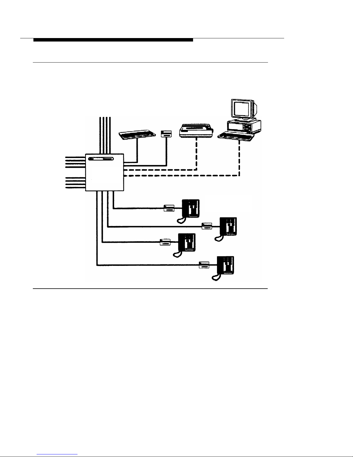
Introduction
Admin Admin
Admin
Keyboard
Display
Printer
PC
Central Office
Lines
To MERLIN
Controller
Line Jacks
MERLIN
Identifier
Control Unit
From MERLIN
Controller
MERLIN Identifier
Station Jacks
Display and
MERLIN Telephones
Figure 1.
MERLIN Identifier Components
MERLIN Identifier Control Unit
provides Caller ID functions,
administrative functions, and the MERLIN Identifier database. For
each incoming call, the MERLIN Identifier system sends the
following information to the MERLIN Identifier Displays: the last
two digits of the line number on which the call was received, the
time and date of the call as recorded at the Central Office, and if
the caller’s exchange provides Caller ID service, the caller’s
telephone number as well.
MERLIN Identifier Components and Features
3
Page 11

Introduction
If the telephone number matches a record in the MERLIN
Identifier database that has a name associated with it, the
MERLIN Identifier system also sends the caller’s name to the
MERLIN Identifier Displays. If the Central Office sends the caller’s
name with the telephone number and there is no matching name
in the database, the name supplied by the Central Office is sent
to the MERLIN Identifier Displays.
MERLIN Identifier Displays
display the information sent to
them from the MERLIN Identifier Control Unit—both Caller ID
information as it is received and MERLIN Identifier database
information that corresponds to the caller’s telephone number. If
the caller’s MERLIN Identifier database record has a “priority
flag,” the MERLIN Identifier Display can be set to beep to call
attention to it. The MERLIN Identifier Display can also be set to
beep at every call, or never to beep at all. Users can scroll
through the information displayed for the last 18 callers on each of
up to four Central Office lines.
See the MERLIN Identifier User’s Quick Reference for more
information on MERLIN Identifier Displays.
MERLIN Identifier Administrative Display and Keyboard
are
used by the system administrator to set up the MERLIN Identifier
system and maintain the MERLIN Identifier database. MERLIN
Identifier command menus, messages, and prompts are
displayed on the Administrative Display. Single character
administrative commands are entered on the Administrative
Keyboard and simultaneously displayed on the Administrative
Display.
Administrative PC
is a customer-provided PC that can be used
in place of the standard Administrative Display and keyboard to
provide additional administrative features such as expanded
menus and prompts, and data transfers between the MERLIN
Identifier database and database software running on the PC.
4
MERLIN Identifier Components and Features
Page 12

Introduction
NOTE:
The Administrative PC requires asynchronous communications
software to communicate with the MERLIN Identifier Control Unit.
Serial Printer
provides a printed copy of Caller ID information,
such as line number, caller’s telephone number, caller name from
MERLIN Identifier database, and day and time of call, as it is
received by the the MERLIN Identifier Control Unit. This printed
copy can be used as a source of data for the MERLIN Identifier
database. If desired, you can connect a PC instead of the printer
to capture the Caller ID output for use in your own custom PC
applications.
Supported Telephone Equipment
The MERLIN Identifier system supports all past and present
MERLIN telephone systems and stations.
MERLIN Identifier Database
The MERLIN Identifier Control Unit lets you create and maintain a
database of approximately 2500 caller records consisting of a
10-digit telephone number and a 16-character name. If many of
the caller names are less than 16 characters, even more caller
records can be maintained.
The system administrator is responsible for creating and
maintaining the MERLIN Identifier database. Using either the
Administrative Display and Keyboard, or optionally, an
Administrative PC, the system administrator enters the telephone
numbers and names of callers into the MERLIN Identifier
database as they should appear on the MERLIN Identifier
Displays.
MERLIN Identifier Components and Features
5
Page 13

Introduction
Database Integrity
The following features ensure the integrity of the caller information
in the MERLIN Identifier database:
■
■
■
■
Password entry is required before access to
administrative database functions is permitted
Access to administrative functions “times-out” after 120
seconds of keyboard inactivity—password entry is
required before the administrative functions can be
accessed again
Record locking during edit prevents the “half-edited”
database records from displaying at the MERLIN
Identifier Display—the original, unedited record displays
instead
Capacitor power backup retains data for a minimum of
72 hours following power loss
Database Transfers
The system administrator can transfer caller information between
the MERLIN Identifier database and a database management
system running on the Administrative PC. Both database upload
and download transfers are supported using asynchronous
communications software, such as PROCOMM PLUS® or
Windows Terminal*, and either XMODEM or text file transfer
protocols.
*
Although other asynchronous communications software may work, only
PROCOMM PLUS 2.01 and Windows 3.1 Terminal are recommended for
use with MERLIN Identifier.
6
MERLIN Identifier Components and Features
Page 14

Introduction
System Administration Overview
The MERLIN Identifier system administrator is initially responsible
for the planning, set up, and installation of the MERLIN Identifier
system. This requires the following efforts:
Ordering Caller ID service for the lines to be monitored by
■
■
■
■
■
■
the MERLIN Identifier system
Determining the location and requirements for the MERLIN
Identifier equipment
Identifying the MERLIN phones that require MERLIN
Identifier Displays (each requires an AC outlet nearby)
Determining whether to administer MERLIN Identifier from
a PC or a MERLIN Identifier Display and keyboard
Setting up MERLIN Identifier database maintenance
procedures and source data documents
Setting up and maintaining a PC database management
system, if one is used
Once the MERLIN Identifier system has been installed, the system
administrator is responsible for maintaining the MERLIN Identifier
database and training MERLIN Identifier users.
System Administration Overview
7
Page 15

Introduction
8
System Administration Overview
Page 16

Installing the MERLIN
Identifier System
2
Installing the MERLlN® Identifier system consists of the following
installation steps:
Step 1.
Step 2.
Step 3.
Step 4.
Step 5.
Step 6.
Step 7.
Verifying that you have the necessary MERLIN Identifier
components
Mounting the MERLIN Identifier Control Unit
Wiring the MERLIN Identifier Control Unit
Mounting the MERLIN Identifier Displays
Wiring the MERLIN Identifier Displays
Connecting the Administrative components
Setting up MERLIN Identifier parameters
9
Page 17

Installing the MERLIN Identifier System
STEP 1:
Verify MERLIN
Identifier Components
Make sure that you have the following before you install the
MERLIN identifier system:
■
■
■
■
■
■
Caller ID service on the Central Office lines to be
monitored by the MERLIN Identifier system
MERLIN Identifier components for your planned
installation
AC power outlets for each MERLIN Identifier Display, the
MERLIN Identifier Control Unit, and any optional
equipment
Required MERLIN
Identifier Components
Your AT&T MERLIN Identifier system shipment should contain the
components you ordered. Verify your shipment against the
individual MERLIN Identifier parts list options found in Appendix B.
At a minimum, your order should contain the following:
MERLIN Identifier Control Unit and cover, 9 volt 1 ampere
power transformer, modular cords with RJ45 plugs,
modular cords with RJ11 plugs, and mounting screws
For keyboard administration, a keyboard, keyboard
adapter cable, two keyboard mounting brackets,
MERLIN Identifier Display, display wall mounting, 9 volt
200 milliampere power transformer, a modular cord with
RJ45 plugs, and mounting screws
For PC administration, a modular cord with RJ45 plugs
and RJ45-to-DB9 and RJ45-to-DB25 adapters
10
STEP 1:
Verify MERLIN Identifier Components
Page 18

Installing the MERLIN Identifier System
■
One or more MERLIN Identifier Displays, each with a
9 volt 200 milliampere power transformer, a modular
cord with RJ45 plugs, a modular cord with RJ11 plugs,
and a phone mounting bracket or a display wall
mounting and mounting screws
Optional Equipment
If you ordered it, your shipment may also include a serial printer,
two modular cords with RJ45 plugs, an RJ45-to-DB9 adapter, and
an RJ45-to-DB25 adapter.
STEP 2:
Mount the MERLIN
Identifier Control Unit
The MERLIN Identifier Control Unit should be mounted near the
MERLIN Controller—placed on a desk, on a shelf, or mounted on
a plywood sheet attached to the wall studs. If you place the
MERLIN Identifier Control Unit on a desk or shelf, make sure that
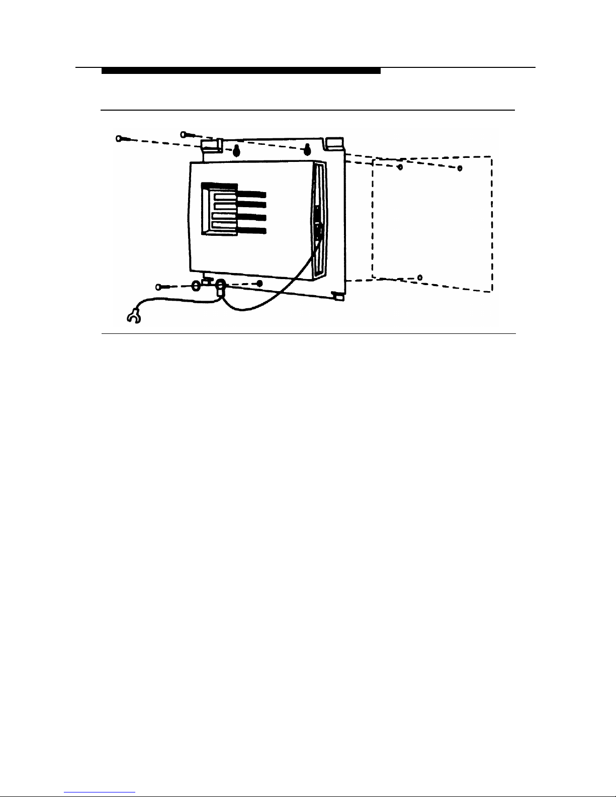
you have adequate space to work. If you mount the MERLIN
Identifier Control Unit on the wall, refer to Figure 2 as you follow
the instructions below:
1.
Position the MERLIN Identifier Control Unit on the plywood
surface near the MERLIN Controller and an AC power
outlet, and mark points on the plywood surface for the pilot
holes.
WARNING:
Do not use the supplied mounting screws if you are
mounting the MERLIN Identifier Control directly to the wall
and not to plywood. Instead, use wall fasteners, such as
screws with expansive wall anchors or Molly bolts, to
ensure permanent and secure mounting.
STEP 2:
Mount the MERLIN Identifier Control Unit
11
Page 19
Installing the MERLIN Identifier System
Figure 2.
Mounting the MERLIN Identifier Control Unit
2.
3.
4.
5.
■
■
Remove the MERLIN Identifier Control Unit and drill pilot
holes in the mounting surface for the #6 x 1/2-inch selftapping screws (supplied) or for the wall fasteners you
have selected.
Do one of the following:
If you are mounting to plywood, align the mounting
holes in the MERLIN Identifier Control Unit base with
the pilot holes and drive #6 x 1/2-inch screws
through the top two mounting holes.
If you are mounting directly to the wall, first install the
wall fasteners, then align the mounting holes in the
MERLIN Identifier Control Unit base with the pilot
holes and drive the screws or bolts through the top
two mounting holes.
Drive a screw or bolt through the lockwasher, grounding wire
eyelet terminal, and bottom mounting hole.
Attach the grounding wire spade terminal to an approved
ground.
12
STEP 2:
Mount the MERLIN Identifier Control Unit
Page 20
Installing the MERLIN Identifier System
STEP 3:
Wire the MERLIN
Identifier Control Unit
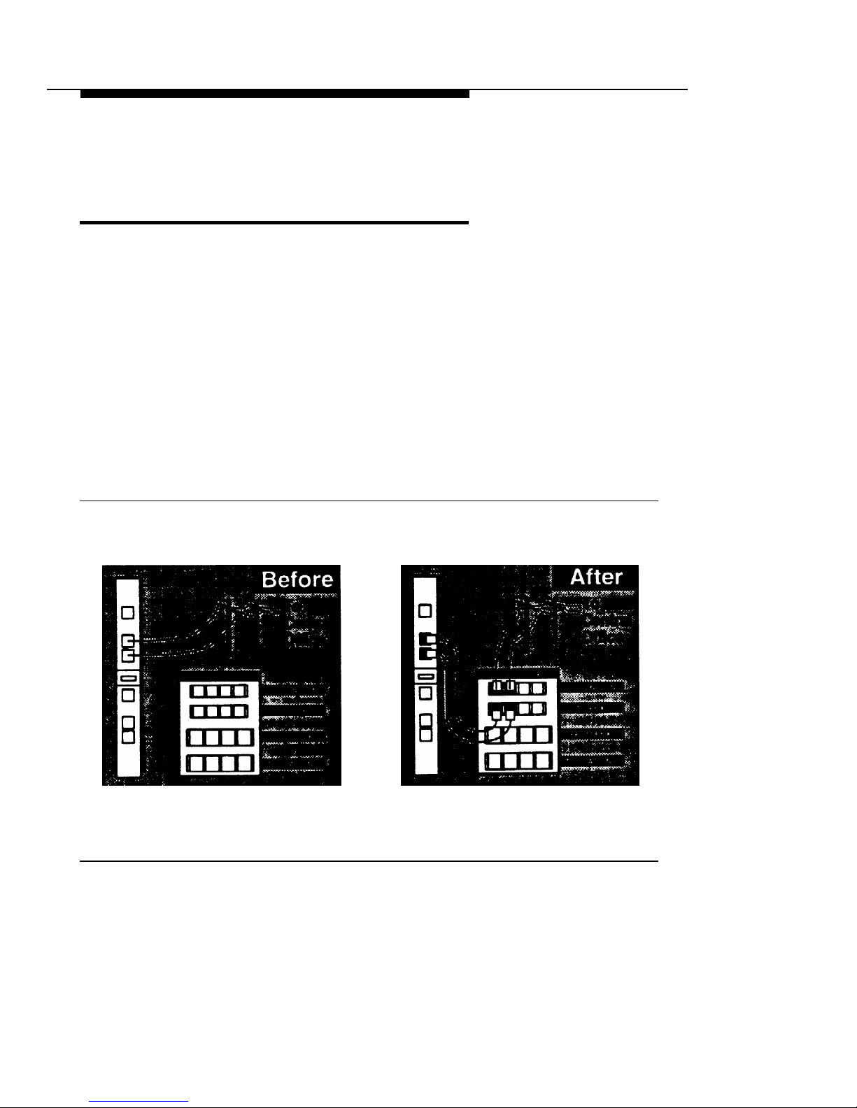
Refer to Figures 3 and 4 as you follow the instructions below to
wire the MERLIN Identifier Control Unit:
1.
Disconnect the Central office line cords from the MERLIN
Controller jacks labeled “LINES” and plug them into the
corresponding MERLIN Identifier Control Unit jacks labeled
“C.O. LINES IN” (see Figure 3).
NOTE:
If it has not already been done, you should label all lines
going in and coming out of the MERLIN Controller.
Figure 3.
Rerouting the Central Office Lines
STEP 3:
Wire the MERLIN Identifier Control Unit
13
Page 21
Installing the MERLIN Identifier System
2.
3.
4.
Using the modular cords with RJ11 plugs, bridge each
Central Office line to the MERLIN Controller by plugging
one end into the MERLIN Identifier Control Unit jacks
labeled “TO PBX” and the other end into the MERLIN
Controller jacks labeled “LINES” (see Figure 3).
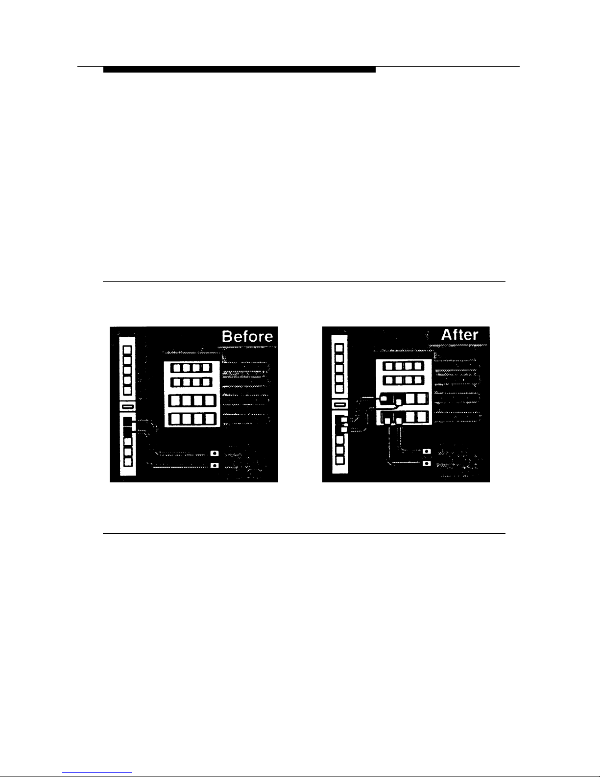
Disconnect the station line cords from the MERLIN
Controller jacks labeled “STATlONS” and plug them into
the corresponding MERLIN Identifier Control Unit jacks
labeled “TO STATIONS” (see Figure 4).
Figure 4.
Rerouting the Station Lines
Using the modular cords with RJ45 plugs, bridge each
station line to the MERLIN Controller by plugging one end
into the MERLIN Identifier Control Unit jacks labeled
“FROM PBX” and the other end into the MERLIN Controller
jacks labeled “STATIONS” (see Figure 4).
14
STEP 3:
Wire the MERLIN Identifier Control Unit
Page 22

Installing the MERLIN Identifier System
STEP 4:
Mount the MERLIN
Identifier Display Units
MERLIN Identifier Display units can be mounted directly on a wall
or to the MERLIN telephone. Refer to Figure 5 as you follow the
instructions to mount the MERLIN Identifier Display units.
Figure 5.
Mounting the MERLIN Identifier Display Units
STEP 4:
Mount the MERLIN Identifier Display Units
15
Page 23

Installing the MERLIN Identifier System
Wall Mounting
To mount the MERLIN Identifier Display unit to the wall, follow the
instructions below:
1.
2.
3.
4.
Position the wall mounting bracket on the wall near the
MERLIN telephone and an AC power outlet, and mark
points for the pilot holes.
Remove the wall mounting bracket, drill pilot holes, and
install the plastic screw anchors.
Reposition the wall mounting bracket over screw anchors
and drive the #6 x 1/2-inch self-tapping screws through the
mounting holes and into the anchors.
Align the slots on the back of the MERLIN Identifer Display
with the three prongs on the wall mounting bracket, and
snap the MERLIN Identifier Display into place.
Telephone Mounting
To mount the MERLIN Identifier Display unit to a MERLIN
telephone, follow the manufacturer’s instructions included with the
telephone mounting bracket.
16
STEP 4:
Mount the MERLIN Identifier Display Units
Page 24

Installing the MERLIN Identifier System
STEP 5:
Wire the MERLIN
Identifier Display Units
Refer to Figure 6 as you follow the instructions to connect the
MERLIN Identifier Display unit to the MERLIN telephone and to
a PC.
Figure 6.
Wiring the MERLIN Identifier Display Units
STEP 5:
Wire the MERLIN Identifier Display Units
17
Page 25

Installing the MERLIN Identifier System
Connecting the Display to a
MERLIN Telephone
Follow the instructions below to wire MERLIN Identifier Display
units to MERLIN telephones:
Remove the station cord from the back of the MERLIN
telephone and plug it into the MERLIN Identifier Display
jack labeled “LINE.”
1.
2.
3.
1.
Plug one end of the 18 inch, modular cord with RJ45 plugs
into the MERLIN Identifier Display jack labeled “TEL” and
the other end into the jack on the back of the MERLIN
telephone.
Plug the 9 volt 200 milliampere transformer power cord into
the MERLIN Identifier Display port labeled “9V-DC” and the
transformer into an AC power outlet.
The MERLIN Identifier Display should display the following
to show that it is powered on:
MERLIN IDENTIFIER
Connecting the Display to a PC
A PC running a purchased, Windows™-based contact
management software application or asynchronous
communications software can be used to capture Caller ID
information from a MERLIN Identifier Display. The MERLIN
Identifier Displays come with a modular cord and an RJ11-to-DB9
adapter. If your PC’s serial port requires a DB25 connection, you
must purchase a DB9-to-DB25 adapter.
To connect a PC to a MERLIN Identifier Display, refer to Figure 6
and follow the steps below:
Unplug the the MERLIN Identifier Display power cord and
switch off the PC.
18
STEP 5:
Wire the MERLIN Identifier Display Units
Page 26

Installing the MERLIN Identifier System
2.
3.
4.
5.
■
■
Connect one end of the modular cord into the MERLIN
Identifier Display jack labeled “RS232” and the other end to
the jack in the RJ11-to-DB9 adapter.
Connect the DB9 adapter to the PC’s serial port, either
COM1 or COM2.
Start the PC and either the contact management software
application or the asynchronous communications software.
If you use the contact management software
application, follow the manufacturer’s instructions to
set up and operate the software.
If you use your own communications software, set up
the PC’s communications software as a direct
connection with the parameters as given under
“Connecting the Administrative PC” in “STEP 6,” and
start the communications program capture feature.
Reconnect the MERLIN Identifier Display power cord.
STEP 6:
Connecting
Administrative Components
You can administer the MERLIN Identifier system from either an
Administrative Display using a PC Keyboard or from an
Administrative PC running asynchronous communications
software. Refer to Figure 7 as you follow the instructions to
connect your administrative components.
WARNING:
To prevent damage to the MERLIN Identifier Control Unit and
equipment you connect to it, remove their power cords before
connecting them.
STEP 6:
Connecting Administrative Components
19
Page 27

Installing the MERLIN Identifier System
Figure 7.
Connecting Administrative Components
Connecting the Administrative
Keyboard and Display
To connect the Administrative Keyboard and Display to the
MERLIN Identifier Control Unit:
1.2.Plug the Administrative Keyboard cord to the MERLIN
Identifier Control Unit port labeled “Keyboard.” Use the
supplied adapter cable if your keyboard cord ends with a
5-pin DIN connector.
If no shelf or desk space is available for the Administrative
Keyboard, mount the keyboard wall mounting brackets on
the wall near the MERLIN Identifier Control Unit using the
#6 x 1/2-inch self-tapping screws (supplied) and plastic
wall anchors.
20
STEP 6:
Connecting Administrative Components
Page 28

Installing the MERLIN Identifier System
3.
4.
5.
6.
7.
8.
Follow the instructions under “STEP 4” to mount the MERLIN
Identifier Display to be used as the Administrative Display.
Plug one end of the modular cord into the Administration
Display jack labeled “LINE” and the other end into the
MERLIN Identifier Control Unit jack labeled “Admin
Display.”
Slide the Administrative Mode switch to the “Keybd/Display”
position.
Plug the transformer power cord into the MERLIN Identifier
Administration Display port labeled “9V-DC” and the
transformer into an AC power outlet.
The MERLIN Identifier Control Unit power LED should light
and the
ENTER PASSWORD
prompt should display on the
Administrative Display screen.
Switch on the power to the MERLIN Identifier Control Unit.
Install the MERLIN Identifier Control Unit cover by sliding it
into position from the top.
Connecting the Administrative PC
The Administrative PC can be situated in the same room as the
MERLIN Identifier Control Unit or located in another room. If you
want to locate the Administrative PC in another room, you will
need to install a jack near the MERLIN Identifier Control Unit and
another jack near the Administrative PC, and run an inside wire
between the two jacks before using the procedure that follows.
To connect an Administrative PC to the MERLIN Identifier Control
Unit:
1.
labeled “RS232 Admin.”
Connect the RJ45-to-DB9 adapter labeled “Serial Port
Controller” to the MERLIN Identifier Control Unit port
STEP 6:
Connecting Administrative Components
21
Page 29

Installing the MERLIN Identifier System
2.
3.
4.
5.
Connect one of the following RJ45 adapters to the
Administrative PC’s serial port:
■
■
■
■
For a 9-pin COM port, connect the RJ45-to-DB9
adapter labeled “Serial Port PC.”
For a 25-pin COM port, connect the RJ45-to-DB25
adapter labeled “Serial Port PC.”
Do one of the following:
If the Administrative PC is in the same room as the
MERLIN Identifier Control Unit, connect a modular
cord with RJ45 plugs directly between the “Serial
Port Controller” adapter and the “Serial Port PC”
adapter.
If the Administrative PC is in a separate room,
connect a modular cord with RJ45 plugs directly
between the “Serial Port Controller” adapter on the
MERLIN Identifier Control Unit and its designated
wall jack. Then connect a modular cord with RJ45
plugs directly between the “Serial Port PC” adapter
on the Administrative PC’s serial port and its
designated wall jack.
Slide the MERLIN Identifier Control Unit Administrative Mode
switch to the “RS232 Admin” position.
Start the Administrative PC and the communications
software.
22
STEP 6:
Connecting Administrative Components
Page 30

Installing the MERLIN Identifier System
6.
7.
8.
Set up the Administrative PC’s communications software as
a direct connection with the following parameters:
Port: COM1 or COM2 to match physical connection
Speed: 1200 bps
Data length: 8 bits
Stop Bits: 1 bit
Parity: none
Duplex: full
Plug the 9 volt 1 ampere transformer power cord into the
MERLIN Identifier Control Unit port labeled “9V-DC” and
the transformer into an AC power outlet.
The MERLIN Identifier Control Unit power LED should light
and the
ENTER PASSWORD
prompt should display on the
Administrative PC screen.
Install the MERLIN Identifier Control Unit cover by sliding
into position from the top.
Connecting a Serial Printer
Depending on your MERLIN Identifier system requirements, you
may also want to connect a serial printer to the MERLIN Identifier
Control Unit to collect Caller ID information.
The serial printer can be situated in the same room as the
MERLIN Identifier Control Unit, or located in another room. If you
want to locate the serial printer in another room, you will need to
install a jack near the MERLIN Identifier Control Unit and another
jack near the serial printer, and run an inside wire between the
two jacks before using the procedure that follows.
To connect the serial printer to the MERLIN Identifier Control Unit,
refer to Figure 7 and follow the steps below:
1.
Unplug the the MERLIN Identifier Control Unit power cord
and the printer’s or PC’s power cord.
STEP 6:
Connecting Administrative Components
23
Page 31

Installing the MERLIN Identifier System
2.
3.
4.
5.
6.
Connect the RJ45-to-DB9 adapter labeled “Printer Port
Controller For use with Printer only” to the MERLIN Identifier
Control Unit port labeled “Serial Printer.”
Connect the RJ45-to-DB25 adapter labeled “Serial Printer”
to the printer’s serial port.
Do one of the following:
■
■
If the serial printer is in the same room as the MERLIN
Identifier Control Unit, connect a modular cord with
RJ45 plugs directly between the “Printer Port
Controller For use with Printer only” adapter and the
“Serial Printer” adapter.
If the serial printer is in a separate room, connect a
modular cord with RJ45 plugs directly between the
“Printer Port Controller For use with Printer only”
adapter on the MERLIN Identifier Control Unit and its
designated wall jack. Then connect a modular cord
with RJ45 plugs directly between the “Serial Printer”
adapter on the serial printer and its designated wall
jack.
Connect the power cord to the printer or PC and an AC
power outlet.
Reconnect the MERLIN Identifier Control Unit power cord.
Be sure to follow the instructions in “Setting Up the Printer Serial
Port” in “STEP 7” to set up the correct line termination required by
the serial printer.
24
STEP 6:
Connecting Administrative Components
Page 32

Installing the MERLIN Identifier System
Connecting a PC
Instead of the Printer
A PC running asynchronous communications software can be
used instead of a serial printer to capture Caller ID information
from the MERLIN Identifier Control Unit. If you are using an
Administrative PC, the same PC can be used if it has a free serial
port or you install a switch box.
The PC can be situated in the same room as the MERLIN
Identifier Control Unit or located in another room. If you want to
locate the PC in another room, you will need to install a jack near
the MERLIN Identifier Control Unit and another jack near the PC,
and run an inside wire between the two jacks before using the
procedure that follows.
To connect a PC to the MERLIN Identifier Control Unit, follow the
steps below:
1.
2.
3.
Unplug the the MERLIN Identifier Control Unit power cord
and switch off the PC.
Connect the RJ45-to-DB9 adapter labeled “Printer Port
Controller Serial Port Only” to the MERLIN Identifier Control
Unit port labeled “Serial Printer.”
Connect one of the following adapters to the PC’s serial port:
■
■
For a 9-pin COM port, connect the RJ45-to-DB9
adapter labeled “Serial Port PC.”
For a 25-pin COM port, connect the RJ45-to-DB25
adapter labeled “Serial Port PC.”
STEP 6:
Connecting Administrative Components
25
Page 33

Installing the MERLIN Identifier System
4.
5.
6.
7.
8.
Do one of the following:
■
■
If the PC is in the same room as the MERLIN Identifier
Control Unit, connect a modular cord with RJ45
plugs directly between the “Printer Port Controller
Serial Port Only” adapter and the “Serial Port PC”
adapter.
If the PC is in a separate room, connect a modular
cord with RJ45 plugs directly between the “Printer
Port Controller Serial Port Only” adapter on the
MERLIN Identifier Control Unit and its designated
wall jack. Then connect a modular cord with RJ45
plugs directly between the “Serial Port PC” adapter
on the PC’s serial port and its designated wall jack.
Reconnect the PC’s power cord and start the PC and the
communications software.
Set up the PC’S communications software using the
parameters as given under “Connecting the Administrative
PC” in “STEP 6.”
Start the communications program capture feature.
Reconnect the MERLIN Identifier Control Unit power cord.
26
STEP 6:
Connecting Administrative Components
Page 34

Installing the MERLIN Identifier System
STEP 7:
Set Up MERLIN
Identifier Parameters
■
■
■
■
■
■
■
■
■
After the MERLIN Identifier system has been installed, the
following initial system parameters must be set up:
Changing the default administration password
Setting up the telephone lines
Setting up the serial port
Notes on Entering Data
The MERLIN Identifier system simplifies the entry of commands
and database information in the following ways:
Displaying upper-case for all letters, whether you type
them in upper- or lower-case
Employing mnemonic commands that are entered by
typing a single character
Supporting type-over edit mode only (<Insert> key not
supported)
Supporting the <Backspace> and <Tab> keys to position
the cursor
(Administrative PC Only) Supporting a Beginner mode
where prompts and menus are displayed, and an
Advanced mode where menus are displayed only upon
request
(Administrative PC Only) Displaying a menu of commands
when you enter ? or H (for Help)
STEP 7:
Set Up MERLIN Identifier Parameters
27
Page 35

Installing the MERLIN Identifier System
Entering the Administration Password
You can access the MERLIN Identifier system administration and
database functions only by entering the administration password.
The password is
IDENTIFIER
until you change it.
■
To enter the administration password, type the password
and press <Enter>.
To prevent others from viewing the password, the MERLIN
Identifier system does not display the password as you
type it.
After you enter the password, the MERLIN Identifier system
displays the menu as shown in Figure 8.
Administrative Display Screen
New Edt Srch Del
F+.-$RZQ
Administrative PC Screen
Merlin Identifier version v1.24
Main command menu:
H(elp) or ?
- print main command menu (this menu)
M(ode)
------ switch between Advanced and beginner modes
N(ew)
------- add an entry to the database
S(earch)
---- find the next entry containing a pattern
R(e-search)
- search again with the same pattern
F(irst)
----- move to first name/number in database
+ or = ------
move to next name/number
. (period)
-- show currant name/number
- (minus)
--- move to previous name/number
E(dit)
------ edit currant name/number
D(elete)
---- delete current name/number
P(rint)
----- print entire database on screen
T(ransfer)
-- send or receive name/number pairs
Z ----------- set system parameters
Q(uit) ------ leave administration mode
<Esc>
------- general process interruption key
$ ----------- display numbe of database entries
Figure 8. MERLIN Identifier Administration Menu
28
STEP 7:
Set Up MERLIN Identifier Parameters
Page 36

Installing the MERLIN Identifier System
See Appendix A for a complete list of the MERLIN Identifier
system administration and database commands.
NOTE:
Be sure to log off by entering Q (for
Quit)
on the Administrative
Keyboard or pressing <Esc> at the Administrative PC until the
ENTER PASSWORD
prompt displays. The MERLIN Identifier
Control Unit also logs you off automatically if there is no keyboard
activity for 120 seconds.
Changing the Administration Password
The administration password prevents unauthorized users from
accessing MERLIN Identifier system administration and database
functions. The password can be any combination of 1–12
alphabetic or numeric characters. For security reasons, you
should use at least 6 characters for the password and change the
password periodically.
To change the administration password, follow the instructions
below:
1.
2.
3.
4.
5.
6.
7.
Enter the current password.
Enter Z to access the System Parameter menu.
Enter P (for
Password).
Enter the current password when prompted.
Enter the new password when prompted. (It does not
display.)
Enter the new password again when prompted to confirm
that you entered it correctly. (It does not display.)
Press <Esc> to exit the System Parameter menu.
STEP 7:
Set Up MERLIN Identifier Parameters
29
Page 37

Installing the MERLIN Identifier System
Setting Up the Telephone Lines
The MERLIN Identifier system lets you attach MERLIN Identifier
Displays to up to four Central Office telephone lines. The MERLIN
Identifier Display shows the last two digits of the telephone line
numbers you set up.
To assign telephone numbers, follow the instructions below:
1.
2.
3.
4.
5.
6.
■
■
1.
2.
Enter the Administration password.
Enter
Z
to access the System Parameter menu.
Enter the number, 1–4, of the telephone line you want to set.
Enter the last four digits of the telephone line number.
You must enter all four digits even though only the last two
digits show on the MERLIN Identifier Displays.
Repeat Steps 3 and 4 for each line number to be monitored
by a MERLIN Identifier Display.
Press <Esc> to exit the System Parameter menu.
Setting Up the Printer Serial Port
Serial printers require one of the following line terminations:
Carriage return (<CR>)
Carriage return plus a line feed (<CR><LF>)
To set up the MERLIN Identifier Control Unit printer port, follow the
instructions below:
Verify the line termination required by the printer.
Enter the Administration password.
30
STEP 7:
Set Up MERLIN Identifier Parameters
Page 38

Installing the MERLIN Identifier System
3.
4.
5.
Enter Z to access the System Parameter menu.
The current printer status is displayed, either
<CR> only
or
<CR><LF>.
Type C to toggle the line termination between a carriage
return (<CR>) and a carriage return plus a line feed
(<CR> <LF>).
Press <Esc> to exit the System Parameter menu.
STEP 7:
Set Up MERLIN Identifier Parameters
31
Page 39

Installing the MERLIN Identifier System
32
STEP 7:
Set Up MERLIN Identifier Parameters
Page 40

Administering the
MERLIN Identifier
Database
3
MERLIN Identifier
Database Description
The MERLlN® Identifier database stores records in the following
format:
PAAAAAAAAAAAAAAAANNNNNNNNNN
where:
P
is a Priority flag.
AAAAAAAAAAAAAAAA
is the 1-to-16 character caller
name.
NNNNNNNNNN
is the caller’s 10-digit telephone number.
The MERLIN Identifier database can store approximately 2500
records. Because the MERLIN Identifier database stores caller
records using variable record-length format, more memory is
available to store additional records when caller names are less
than the 16 characters allotted. For example, if 900 records use
13-character names instead of all 16 characters, an additional
100 database records with 16-character names could be stored.
MERLIN Identifier Database Description
33
Page 41

Administering the MERLIN Identifier Database
Caller Names
All upper-case alphabetic characters and punctuation marks can
be used for caller names. The MERLIN Identifier system stores
database records in alphabetical order by caller name. To
facilitate recognition of names on the MERLIN Identifier Displays,
always record caller names in the same format—such as last
name first. For example, enter SUE WALLACE and BERT
WASHINGTON into the database as
WALLACE, SUE
and
WASHINGTON, BERT,
or
SUE WALLACE
and
BERT
WASHINGTON,
but not
WALLACE, SUE
and
BERT
WASHINGTON.
Telephone Numbers
Telephone numbers are stored in the database using standard
area code, exchange, and number format. All 10 digits of the
telephone number must be used.
Depending on your data collection and call tracking needs, you
may not want to differentiate calls based on all digits of telephone
numbers. The MERLIN Identifier system lets you substitute the
question mark (“?”) as a wild-card character in place of individual
digits in the telephone number.
34
MERLIN Identifier Database Description
Page 42

Administering the MERLIN Identifier Database
Advantages of Using the
Wild-Card Character
Using one or more wild-card characters offers the following
advantages in storing telephone numbers in the database and
displaying Caller ID information:
■
■
■
■
Each wild-card character used in a telephone number
replaces 10 individual digits (0 through 9)—thus a single
wild-card character has the potential to reduce the
database by 9 records, two wild-card characters have
the potential to reduce the database by 99 records, and
so on
Selected ranges of telephone numbers could be assigned
to a single record
All telephone numbers within a calling exchange could be
represented by just a single database record
All telephone numbers within an area code could be
represented by just a single database record
The following examples show how the wild-card character can be
used to address business needs.
Example 1:
A local delivery service in the 901 area code has
been monitoring its telephone calls and finds that a significant
number of calls involved telephone numbers 555-4100 to
555-4199. A further check reveals that a single company uses all
100 of those telephone numbers. To use a single database record
to represent all 100 of the company’s telephone numbers, a caller
record with telephone number
901-555-41??
and the
company’s name has been set up in the MERLIN Identifier
database. Now any time a telephone order is placed from
telephone numbers 555-4100 to 555-4199, the delivery service
knows to send the delivery person to the same company.
MERLIN Identifier Database Description
35
Page 43

Administering the MERLIN Identifier Database
Example 2:
The delivery service in “Example 1” only delivers
within a five mile radius. The manager has identified four
surrounding telephone exchanges outside the radius likely to
place an order, but to which deliveries would not be made: 332,
125, 976, and 212. To immediately identify those exchanges to
employees, the following telephone numbers were added to the
MERLIN Identifier database with the name
NO DELIVERY:
901-332-????, 901-125-????, 901-976-????,
and
901-212-????.
Now whenever a delivery request comes in
from those exchanges, the employee politely explains that the
location is outside the delivery range.
Setting Up and
Maintaining the Database
The MERLIN Identifier database enables you to match the names
of frequent callers to their telephone numbers. This database can
be set up in the following ways:
■
■
Using the Administrative Keyboard and Display or
Administrative PC to enter individual caller records
directly into the database from the following sources:
Your files or paper records
Caller ID information output from the serial printer
attached to the MERLIN Identifier Control Unit
Transferring data from computer-based applications:
—
—
—
—
—
Database files
Mailing list files
Plain ASCII text files
36
Setting Up and Maintaining the Database
Page 44

Administering the MERLIN Identifier Database
Maintaining the Database Directly
The following MERLIN Identifier database functions can be
performed from Administrative Keyboard and Display or the
Administrative PC:
■
■
■
■
Adding a new record
Searching for a specific record to display, edit, or delete
Editing an existing record
Deleting an existing record
Adding Database Records
To add a record to the MERLIN Identifier database, follow the
instructions below:
1.
2.
3.
4.
5.
Enter the administration password.
Enter N (for
New).
The MERLIN Identifier system displays the following
characters to prompt the correct entry of the caller record:
----------------
1-to-16 chararcter caller name
-
000-000-0000
Priority flag (default is no priority)
and 10-digit caller telephone
number
Type over the dashes with the name of the caller.
(Priority Callers (Only) Move the cursor to the minus sign (-)
and press the Plus (+) key to identify a priority caller.
Type over the
000-000-0000
with the telephone
number. The MERLIN Identifier ignores dashes and spaces
between the area code, exchange, and line number fields.
Type all 10 digits, including the area code.
Setting Up and Maintaining the Database
37
Page 45

Administering the MERLIN Identifier Database
6.
7.
Press <Enter> to save the record.
If a record with the identical telephone number already
exists, enter
Y
to confirm its replacement.
Repeat Steps 2 through 6 to add more records.
Selecting Database Records
Use the following commands to select a MERLIN Identifier
database caller record for displaying or subsequent
administration tasks:
Command
MERLIN Identifier System Response
F
(First)
Select the first caller record in the database
+
(Plus)
Scroll to the next caller record in the database
. (Period)
Display the currently selected caller record
- (Minus)
Scroll to the previous caller record
$
Display the number of records in the database
The MERLIN identifier database contains the following lines to tell
you when the beginning or end of the database has been reached:
BEGINNING OF DATABASE
END OF DATABASE
38
Setting Up and Maintaining the Database
Page 46

Administering the MERLIN Identifier Database
Searching for Specific
Database Records
To search for a record containing a specific string of characters in
the caller name, follow the instructions below:
1.
2.
3.
Enter the administration password.
Enter S (for
Search).
NOTE:
The search starts from the current record. If you want to
search the entire database, enter F (for
First)
before
entering the Search command.
Enter the string of characters to search for.
The MERLIN Identifier system displays a record with a caller
name containing the search string entered.
Repeating the Last Search
Searches may not always display the caller record you want.
To repeat the search using the same string of characters defined
in the last search:
■
Enter R (for Re-search).
The MERLIN Identifier system displays the next record
with a caller name containing the search string entered.
Setting Up and Maintaining the Database
39
Page 47

Administering the MERLIN Identifier Database
Editing Database Records
To edit the current record after selecting or displaying it, follow the
instructions below:
1.
2.
3.
1.
2.
Enter E (for
Edit).
Move the cursor to the information to be changed and type
the changes.
Press <Enter> to save the record.
If the record already exists, enter Y to confirm its
replacement.
Deleting a Database Record
To delete the current database record after selecting or
displaying it, follow the instructions below:
Enter D (for
Delete).
You are prompted to confirm the deletion.
Enter one of the following:
Y
to delete the record
N
to cancel the deletion
Maintaining the Database Using
File Transfers
■
■
The MERLIN Identifier Transfer command lets you download
MERLIN Identifier database records for use in other applications
or to make a backup copy of the database. The Transfer
command also lets you maintain caller names and telephone
numbers in a PC application and upload the records to the
MERLIN Identifier database.
40
Setting Up and Maintaining the Database
Page 48

Administering the MERLIN Identifier Database
There are no restrictions on downloading MERLIN Identifier
database records to the Administrative PC. However, the
following restrictions apply when uploading records to the
MERLIN Identifier database:
■
■
■
■
■
■
■
Record format must not exceed the following record format
or the record will be discarded by MERLIN Identifier:
PAAAAAAAAAAAAAAAANNNNNNNNNN
where:
P
is “+” to indicate a Priority record.
AAAAAAAAAAAAAAAA
is the 1-to-16 character
caller name.
NNNNNNNNNN
is the caller’s 10-digit telephone number.
Only the first 16 characters of the name are accepted—
any others are discarded
Records must be delimited by a carriage return <CR>; no
field delimiters can be used
First line of the upload file must contain the uppercase
words
BEGINNING OF DATABASE
Last line of the upload file must contain the uppercase
words
END OF DATABASE
File upload is destructive—new records are added and
records with matching phone numbers are overwritten
If more records are uploaded than will fit in the database,
the extra records are discarded and the MERLIN
Identifier system displays the last record that was
successfully uploaded
Setting Up and Maintaining the Database
41
Page 49

Administering the MERLIN Identifier Database
Downloading Database Records
To download records from the MERLIN Identifier database to the
Administrative PC, follow the instructions below:
1.
2.
3.
4.
5.
6.
1.
2.
Start the communications software on the Administrative PC.
Enter the administration password.
Enter
T
(for
Transfer).
Enter one of the following:
■
■
X
to download using the XMODEM protocol
T
to download as standard ASCII text characters
Enter R (for Receive).
Initiate the download file transfer option for the
Administrative PC communications program and specify a
target filename of your own choosing.
Uploading Records
CAUTION:
When uploading a large database during a heavy incoming call
period, some Caller ID data may be missed. It is recommended
that such transfers be made during evening hours or other light
call traffic periods.
It is recommended that you sort the records on your
Administrative PC before you upload them to the MERLIN
Identifier database.
To upload records from the Administrative PC to the MERLIN
Identifier database, follow the instructions below:
Start the communications software on the Administrative PC.
Enter the Administration password.
42
Setting Up and Maintaining the Database
Page 50

Administering the MERLIN Identifier Database
3.
4.
5.
6.
1.
2.
Enter T (for
Transfer).
Enter one of the following:
X
to upload using the XMODEM protocol
■
■
T
to upload as standard ASCII text characters
Enter S (for Send).
Initiate the upload file transfer option for the Administrative
PC communications program.
Changing the
Administration Mode
If you are using the Administrative PC, you can speed up
administration tasks by changing the mode from Beginner (factory
default setting) to Advanced. In Advanced mode, the MERLIN
Identifier system does not display extended prompts or the
command menu unless you type
?
or H for Help.
To toggle the Administration Mode between Beginner and
Advanced, follow the instructions below:
Enter the Administration password.
Enter M (for Mode).
Changing the Administration Mode
43
Page 51

Administering the MERLIN Identifier Database
44
Changing the Administration Mode
Page 52

Troubleshooting
4
If you encounter a problem with MERLlN® Identifier, be sure to
look for possible causes in this chapter before calling the AT&T
Helpline or your AT&T Authorized Dealer.
Common problems
■
■
Many common problems involve loose, physical
connections and loss of power. Be sure to check all
connections, switches, and outlets before calling for help.
If you do not get caller telephone numbers on the MERLIN
Identifier Display units, do the following:
—
—
—
Contact your local telephone company and verify
that you have Caller ID service to the Central Office
lines you want to monitor.
Verify that you have the correct Central Office lines
and station lines connected to the MERLIN Identifier
Control Unit.
Change your automated attendant setting to
answer after 2 or 3 rings (Caller ID information is
transmitted between the first and second ring).
Troubleshooting
45
Page 53

Troubleshooting
Power LED does not light on MERLIN Identifier Control Unit
■
■
■
■
■
■
■
■
Make sure you are using the 9 volt 1 ampere power
transformer and not the 9 volt 200 milliampere power
transformer supplied with the MERLIN Identifier Display
units.
Make sure that the power cord is firmly seated in the
9V-DC port on the MERLIN Identifier Display unit.
MERLIN Identifier Display unit does not appear to have power
Make sure that the power cord is firmly seated in the
9V-DC port on the MERLIN Identifier Display unit.
Check for power at the AC outlet.
MERLIN Identifier Control Unit appears to be locked up
(does not receive calls and/or cannot be administered)
Reset MERLIN Identifier Control Unit by moving
Administrative Mode switch to opposite position and
back again.
Serial printer is not printing
Verify that you are using the correct adapters and the
modular cords.
Verify that you have the correct line termination, either
<CR> or <CR><LF>.
If using inside wiring to connect the printer to the MERLIN
Identifier Control Unit, verify that the correct inside wires
and jacks are being used.
46
Troubleshooting
Page 54

Troubleshooting
Administrative PC does not communicate with the MERLIN
Identifier Control Unit
■
■
■
■
■
■
■
■
■
Verify that the Administrative Mode switch is in the
“RS232 Admin” position.
Verify that you are using the correct adapters and
modular cords.
If using inside wiring to connect the PC to the MERLIN
Identifier Control Unit, verify that the correct inside wires
and jacks are being used.
Verify that you are using the correct PC serial port.
Verify your communication settings for the PC.
PC software does not communicate with the Display unit
Verify that you are using the correct adapters and
modular cords.
Verify that you are using the correct PC serial port.
Verify your communication settings for the PC.
Verify your software installation.
Troubleshooting
47
Page 55

Troubleshooting
48
Troubleshooting
Page 56

Technical Reference
A
MERLIN Identifier System
Record Formats
The MERLlN® Identifier system record formats use the fields that
follow:
P
is either
“-” for a non-Priority
record or “+” for a Priority record
AAAAAAAAAAAAAAAA
the caller name
NNNNNNNNNN
the caller telephone number
LLLL or LL
the four- or two-digit line number
MM/DD
the date of call (month/day)
HH:MM
the time of call (hour:minute)
T A for AM or P for PM
MERLIN Identifier Database Record Format
PAAAAAAAAAAAAAAAANNNNNNNNNN
Serial Printer Output Record Format
LLLL NNN-NNN-NNNN AAAAAAAAAAAAAAAA
MM/DD HH:MM T <CR
or CRLF option>
MERLIN Identifier Display Output Record Format
LL NNNNNNNNNN AAAAAAAAAAAAAAAA MM/DD HH:MMT <CR>
MERLIN Identifier System Record Formats
49
Page 57

Technical Reference
Serial Cable Pin Configurations
The following tables list the pin assignments for the RS232
adapters included with MERLIN Identifier system components.
Adapters are identified by their labels.
NOTE:
All modular cords supplied with the MERLIN Identifier system
components are polarized—other similar-looking modular cords
may not be compatible with the adapter pin configurations.
Serial Port Controller (RJ45-to-DB9)
RJ45 Female
DB9 Male
Red
Pin 2
Yellow
Pin 3
Green
Pin 5
Black
Pin 7
Serial Port PC (RJ45-to-DB9)
RJ45 Female
DB9 Female
Red
Pin 2
Yellow
Green
Black
Pin 3
Pin 5
Pin 7
50
Serial Cable Pin Configurations
Page 58

Technical Reference
Serial Port PC (RJ45-to-DB25)
RJ45 Female
DB25 Female
Red
Pin 5
Yellow Pin 4
Green
Pin 3
Black
Pin 2
Printer Port Controller—For Use with
Printer Only (RJ45-to-DB9)
RJ45 Female
DB9 Female
Red
Pin 8
Yellow Pin 3
Green
Pin 5
Serial Printer (RJ45-to-DB25)
RJ45 Female
DB25 Male
Red
Pin 20
Yellow
Pin 3
Green
Pin 7
N/C
Pins 4, 5, 6, 8
Printer Port Controller (Serial Port Only) (RJ45-to-DB9)
RJ45 Female
DB9 Female
Red
Pin 3
Yellow
Pin 7
Green
Pin 5
Serial Cable Pin Configurations
51
Page 59

Technical Reference
MERLIN Identifier
Command Reference
The following tables define the MERLIN Identifier system
administration commands and indicate whether a command is
only available for administering the MERLIN Identifier system by
the Administrative PC.
Main Menu Commands
Command
Admin.
Description
PC Only
D
(Delete)
No
Deletes the current database record.
E
(Edit)
No
Displays the current database record
for editing.
F
(First)
No
Displays the first record in the database.
H
(Help)
or
?
Yes
Displays the commands available for
the current menu.
M (Mode) Yes
Switches between Beginner and
Advanced system administration
modes.
N (New)
No
Prompts for the entry of a new caller
name.
P
(Print)
Yes
Displays the contents of the MERLIN
Identifier database on the screen.
Q
(Quit)
or
No
Exits the Main menu.
<Esc>
R
(Re-search)
No
Repeats the search using the same
string of characters.
52
MERLIN Identifier Command Reference
Page 60

Technical Reference
Command
Admin.
Description
PC Only
S
(Search)
No Finds the next database record
containing a specified string of
characters.
T
(Transfer)
Yes
Displays the database Transfer Menu.
See “Transfer Subcommands.”
Z
(System
No
Displays the System Parameter Menu.
Parameter)
See “System Parameter
Subcommands.”
+ (plus)
No
Displays the next database record.
-
(minus)
No
Displays the previous database record.
. (period)
No
Displays the current database record.
$ (dollar sign)
No
Displays the number of database
records.
System Parameter Subcommands
Command
Admin.
Description
PC Only
C
(Carriage)
No Switches the serial printer port line
termination between a carriage return
<CR> and carriage return and a
linefeed <CR><LF>.
H
(Help)
Yes
Displays the commands available for
the current menu.
P
(Password)
No
Changes the database password.
D
(Display)
No
Displays all four line numbers.
1
(Line
1)
No
Sets the first line number.
2
(Line
2)
No
Sets the second line number.
MERLIN Identifier Command Reference
53
Page 61

Technical Reference
Command Admin. Description
PC Only
3 (Line 3)
No
Sets the third line number.
4 (Line 4)
No
Sets the fourth line number.
<Esc>
No
Exits System Parameter Menu.
Transfer Subcommands
Command
Admin. Description
PC Only
M (Help)
Yes
Displays the commands available for
the current menu.
R
(Receive)
Yes
Initiates a file download to the MERLIN
Identifier database.
S (Send)
Yes Initiates a file upload from the MERLIN
Identifier database.
T
(Text)
Yes
Specifies a plain ASCII text file transfer.
X
(XMODEM)
Yes Specifies an XMODEM file transfer.
<Esc>
No Exits Transfer Menu.
54
MERLIN Identifier Command Reference
Page 62

Parts Reference
B
The following tables show the parts included with each MERLIN
®
Identifier system component package.
Controller Assembly with Administrative Display and Keyboard
PE Code 6128 KBD COM Code 406 891 556
Parts Name
Quantity
Controller
1 (with mounting plate)
#6 x 1/2" Self-Tapping Screws
3 (for mounting Controller)
Cable phone 8-conductor x 7'
4 (Controller to MERLIN)
Cable phone 4-conductor x 7'
4 (Controller to MERLIN CO lines)
Power Adapter 9V 2.5mm plug
1 (9 Volt 1 Amp plug—Black)
Controller Cable Cover
1
Keyboard 101
1
Keyboard Mounting Brackets
2
Keyboard Cord Adapter
1
Cable phone 8-conductor x 7'
1 (Controller to Admin. Display)
#6 x 1/2" Self-Tapping Screws
6 (for mounting keyboard)
Display Assembly
1 (with wall mounting)
Documentation
3
Parts Reference
55
Page 63

Parts Reference
Controller Assembly with PC Administration
PE Code 6128 PCA COM Code 406 891 564
Parts Name
Quantity
Controller
1 (with mounting plate)
#6 x 1/2" Self-Tapping Screws
3 (for mounting Controller)
Cable phone 8-conductor x 7'
4 (Controller to MERLIN)
Cable phone 4-conductor x 7'
6 (Controller to MERLIN CO
lines) and RS232 connections
Power Adapter 9V 2.5mm plug
1 (9 Volt 1 Amp plug—Black)
Controller Cable Cover
1
Adapter (Serial Port @ Controller)
1
Adapter (Serial Port @ PC DB25)
1
Adapter (Serial Port @ PC DB9)
1
Documentation
2
Display Assembly with Mounting Bracket
PE Code 6128 DIS COM Code 406 891 572
Parts Name
Quantity
Display Unit
1
Power Adapter
1 (9 Volt 200ma plug—Black)
Cable phone 8-conductor x 18"
1 (Display to phone)
Cable phone 4-conductor x 7'
1 (RS232 port to PC)
Adapter (DB9 to 4-conductor
1 (Converter DB9 port to phone
phone)
connector)
Mounting Bracket
1
#6 x 1/2" Self-Tapping Screws
2
and wall anchors
Documentation
1
56
Parts Reference
Page 64

Parts Reference
Display Assembly with Phone Mounting
PE Code 6128 BKT COM Code 406 891 598
Parts Name
Quantity
Mounting Bracket with knob
1
Velcro
1
Database Management Software
PE Code 6128 SFW COM Code 406 891 721
Parts Name
Quantity
Software
1
Documentation
1
Printer Option
PE Code 4200 572 COM Code 406 716 464
Parts Name
Quantity
AT&T Model 572
1
Call Accounting Terminal (CAT)
Printer
Power cord
1
Cable DB9
1
Documentation
1
Parts Reference
57
Page 65

Parts Reference
Parts Ordered Individually
Parts Name
COM Code
Adapter (@ Controller DB9)
406 960 955
For RS232 only
Adapter Kit, PC Administration
406 960 930
Adapter Kit, Printer
406 960 948
Bracket, Display Phone Mount
406 891 937
Cable, Serial Port RS232
406 891 903
Controller to PC
Controller with Mounting Panel
406 891 648
Display
406 891 663
Fixture, Display Wall Mount
406 891 929
Keyboard 101
406 891 655
Manual, MERLIN Identifier
406 891 713
Installation and Administration
MERLIN Identifier User’s Quick
406 891 705
Reference for Display
Software, Database Management
406 891 721
58
Parts Reference
Page 66

MERLIN MLX
Telephone Wiring
C
When the MERLIN® Identifier is used with a MERLIN LEGEND
®
system having MLX™ sets, a pair of installer-wired 104A
termination outlets is required for each MLX set to be connected
to a MERLIN Identifier Display unit.
Figure 9 shows the location of the 104A termination outlets with
respect to the other MERLIN Identifier system components.
Figure 10 shows the internal “strapping” required for the 104A
termination outlets.
Controller
MERLIN MLX
End
Set
104A
Display
To
MERLIN Identifier
End
MERLIN LEGEND
104A
Control Unit
1 2
Controller
MLX Station Module
1 2
MERLIN Identifier
Display
Inside Wiring
Figure 9.
MERLIN Identifier Cabling for MERLIN LEGEND
MLX Sets
MERLIN MLX Telephone Wiring
59
Page 67

MERLIN MLX Telephone Wiring
Outlet
Position
Jack 1
Numbers
Outlet
Position
Numbers
Jack 2
To MERLIN LEGEND
Station Jack
(Controller End)
or
MLX Set
(Display End)
To MERLIN Identifier
Control Unit
(Controller End)
or
MERLIN Identifier
Display
(Display End)
Installer Wiring
(“Strapping”)
Figure 10.
104A Termination Outlet Strappings to Connect
MERLIN LEGEND MLX Sets to MERLIN Identifier
60
MERLIN MLX Telephone Wiring
Page 68

AT&T 518-601-100
Graphics © AT&T 1988
 Loading...