

Page 1
Garage Door Controller Installation Instructions
Product Description
The Garage Door Controller (GDC) is designed to work with your existing
garage door opener. The GDC will give you remote access to open and
close your garage door when used with Digital Life Service. A garage door
opener connected to the GDC can be remotely activated using the Digital
Life Web interface or via mobile devices that communicate with the system.
The GDC connects to the garage door opener’s pushbutton terminals and
communicates with the Digital Life Control Panel (DLC) using 915 MHz
radio signals. A wireless garage door sensor mounts on the garage door
and reports the door’s position to the GDC. When the GDC receives a
command from the DLC, the GDC will open or close the garage door.
Anytime the garage door opener is activated remotely via the Digital Life
System, a warning indicator fl ashes and a beeper sounds for fi ve seconds
before the door begins to move.
If, due to an obstruction or other cause, the door does not completely
open or close when it is activated remotely, the GDC will pause for 30
seconds. After the delay, a second remote activation can be attempted.
If the door does not complete its motion on the second attempt, the GDC
will lock-out and suspend operation. The GDC will report the lock-out
condition to the DLC.
Once the garage door is operated by a garage door remote or locally by
pushing the opener’s wall station button, the DLC will be reset to allow
remote access.
The GDC is powered by a plug-in power supply. The garage door sensor
is powered by a 2032 lithium battery. If the garage door sensor battery is
low, or the case has been opened, it will be reported to the DLC by the
GDC.
A discovery button and status light are provided on the GDC for adding or
removing the device with the DLC.
Four screws and anchors are provided for mounting the GDC. An
adjustable GDC mounting bracket with hardware is supplied for installing
the unit onto the door opener’s hanging hardware. The wireless garage
door sensor mounts with the two screws supplied.
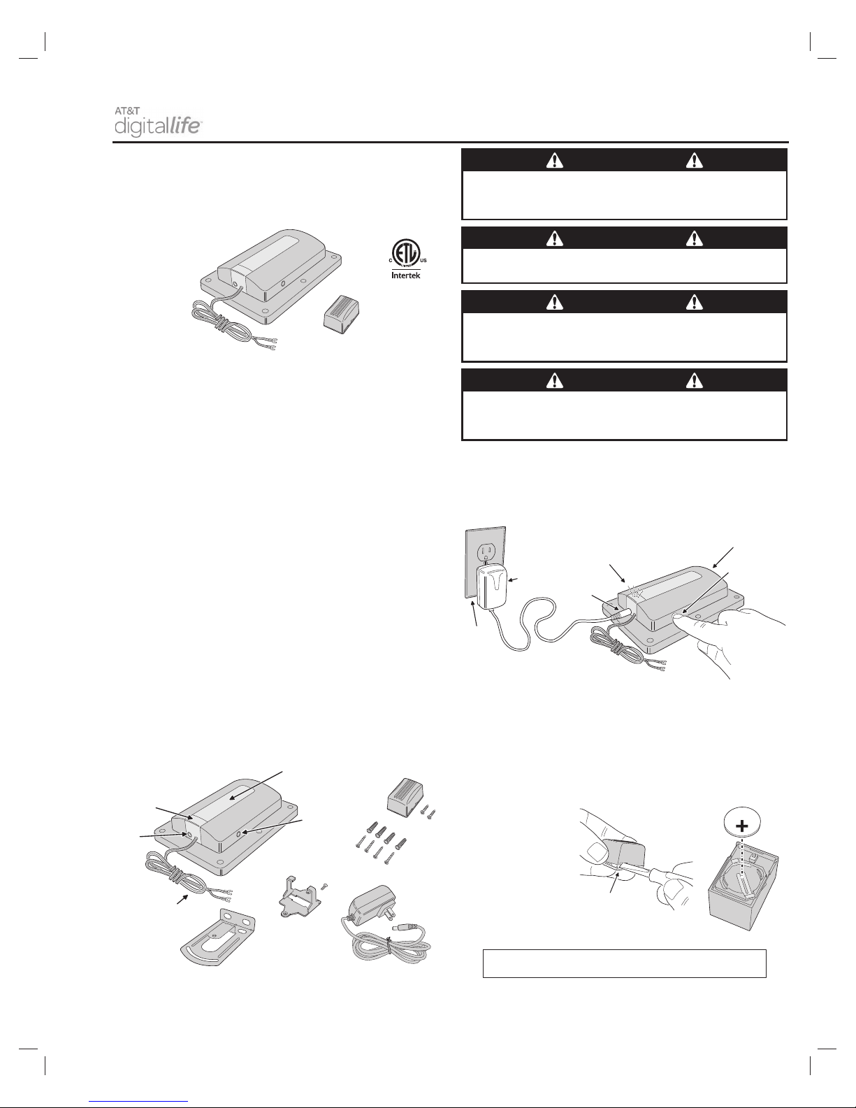
Discovering and Registering the GDC
1. Place the Digital Life Control Panel into Discovery Mode.
2. Plug the GDC power supply into a 115 VAC outlet.
3. Put the GDC into discovery mode by pressing the Discovery Button.
4. Confi rm that the GDC has been discovered.
Garage Door Sensor Battery
To activate the garage door sensor, remove the battery protection pull
strip.
When the system indicates the garage door sensor battery is low, open
the garage door sensor case as shown and replace the old 2032 battery
with a new one. Install the battery, plus side up.
PRINTER’S INSTRUCTIONS:
INSTR,INSTL,SW-ATT-GDC - LINEAR P/N: 235667 X14 - INK: BLACK - MATERIAL: 20 LB. MEAD BOND - SIZE: 11.000” X 8.500” - SCALE: 1-1 - FOLDING: 2-FOLD ALTERNATE - SIDE 1 OF 2
GARAGE DOOR
CONTROLLER (GDC)
POWER
INPUT
JACK
WARNING
LIGHT
DISCOVERY
BUTTON
OPENER
PUSHBUTTON
WIRES
MOUNTING SCREWS
AND ANCHORS
POWER
SUPPLY
GARAGE DOOR
SENSOR
STATUS
INDICATOR
ADJUSTABLE
MOUNTING
BRACKET
POWER
SUPPLY
RETAINING
BRACKET
Figure 1. Garage Door Controller and Garage Door Sensor
Figure 2. Product Features
Figure 3. Discovering the GDC
Figure 4. Garage Door Sensor Battery
WARNING
This operator system is equipped with an unattended
operation feature. This door could move unexpectedly.
NO ONE SHOULD CROSS THE PATH OF A MOVING DOOR!
WARNING
This system can be installed on sectional type (roll up)
doors only (per UL-325).
WARNING
GDC is to be installed only on garage door openers
manufactured after 1992 (models with an operational safety
beam entrapment protection system, per UL-325).
WARNING
The GDC must be mounted in the garage, in sight of the
garage door, where the visual and audible movement warning
indicators can be clearly seen and heard.
WALL
OUTLET
POWER
SUPPLY
POWER
INPUT
JACK
DISCOVERY
BUTTON
GARAGE DOOR
CONTROLLER
(GDC)
STATUS INDICATOR
✴
BLINKS SLOWLY WHILE IN DISCOVERY MODE
✴
LIGHTS FOR 15 SECONDS FOR DISCOVERY SUCCESS
✴ FLASHES FOR 15 SECONDS IF DISCOVERY FAILS
CR2032
PLUS
SIDE
UP !!!
WHEN THE BATTERY IS LOW
REPLACE THE BATTERY WITH
A TYPE CR2032 COIN CELL
TO OPEN THE CASE, TWIST
A SMALL SCREWDRIVER
IN THE CASE SLOT
SLOT
NOTICE TO USERS IN CALIFORNIA - CR COIN CELL LITHIUM BATTERY INFORMATION:
THIS PRODUCT CONTAINS A CR COIN CELL LITHIUM BATTERY WHICH CONTAINS
PERCHLORATE MATERIAL - SPECIAL HANDLING MAY APPLY - SEE
www.dtsc.ca.gov/hazardouswaste/perchlorate
KEEP AWAY FROM SMALL CHILDREN. IF BATTERY IS SWALLOWED, PROMPTLY SEE A DOCTOR.
DO NOT TRY TO RECHARGE THIS BATTERY. DISPOSAL OF USED BATTERIES MUST BE MADE IN
ACCORDANCE WITH THE WASTE RECOVERY AND RECYCLING REGULATIONS IN YOUR AREA.
GARAGE
DOOR
SENSOR
Page 2
Garage Door Controller Installation Instructions
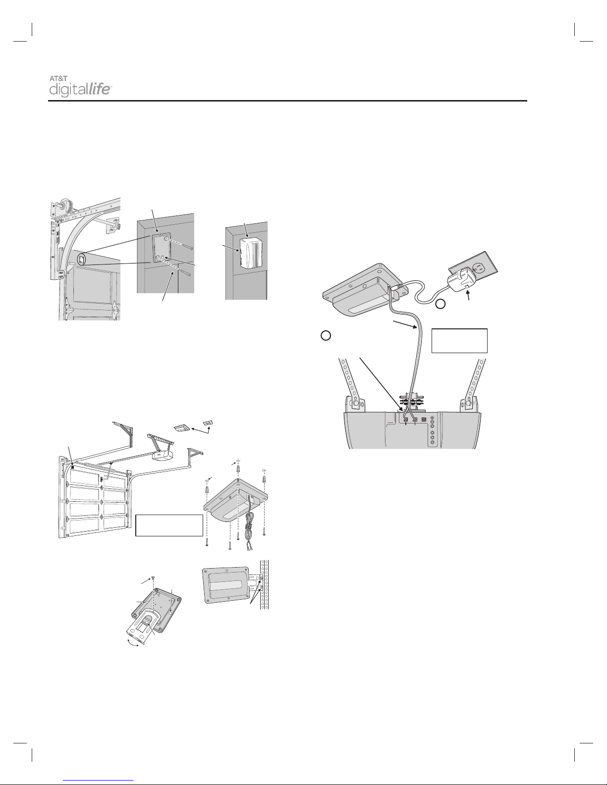
Garage Door Sensor Installation
The garage door sensor installs on the top panel of the garage door.
1. Use the garage door sensor mounting plate as a guide to mark the
mounting holes.
2. Drill two 1/16” pilot holes if necessary.
3. Attach the mounting plate with the two screws provided. Be sure the
post on the mounting plate is on the bottom.
4. Snap the garage door sensor onto the mounting plate. Be sure the
arrow on the side of the garage door sensor case is up.
GDC Installation
The GDC typically mounts on the ceiling near the garage door opener and
power outlet. Alternately, the GDC can be mounted to other structures
with the adjustable mounting bracket supplied (shown in Figure 2).
✓ NOTE: The GDC’s warning lamp must be visible in all door positions.
Use the four screws and anchors to mount the GDC. -OR- Use the
adjustable mounting bracket to mount the GDC.
GDC Connections
The GDC connects to the opener’s pushbutton terminals.
✓ NOTE: Do not disconnect any wires currently connected to the garage
door opener.
1. Connect the GDC wires to the pushbutton terminals on the garage
door opener. Either wire can connect to either terminal.
2. Remove the power outlet wall plate’s center screw (or one end screw
on the decorator style wall plate). Align the power supply retaining
bracket with the wall plate so one of the holes in the bracket aligns
with a screw hole in the wall plate (be sure the clamps of the bracket
are centered over one plug and the other plug is clear). Attach the
bracket and wall plate to the outlet using the fl at head machine screw
provided with the bracket.
3. Plug the power supply into the 115 VAC power outlet by snapping it
into the retaining bracket.
Specifi cations—GDC
• Model: SW-ATT-GDC
• Compatible panels: DLC-100 Digital Life Control Panel
• Operating Temperature: -31° to 158° F (-35° to 70° C)
• Operating Rel. Humidity: 5 to 95%, non-condensing
• Garage Door Sensor Operating Frequency: 433.92 MHz
• GDC Operating Frequency: 915 MHz
FCC Compliance Statement
This equipment has been tested and found to comply with the limits for Class B Digital Device, pursuant
to Part 15 of the FCC Rules. These limits are designed to provide reasonable protection against harmful
interference in a residential installation. This equipment generates and can radiate radio frequency energy
and, if not installed and used in accordance with the instructions, may cause harmful interference to radio
communications. However, there is no guarantee that interference will not occur in a particular installation.
If this equipment does cause harmful interference to radio or television reception, which can be determined
by turning the equipment off and on, the user is encouraged to try to correct the interference by one or more
of the following measures.
• Reorient or relocate the receiving antenna
• Increase the separation between the equipment and receiver
• Connect the equipment into an outlet on a circuit different from that to which the receiver is connected
• Consult the dealer or an experienced radio/TV technician for help.
• Any changes or modifi cations not expressly approved by the party responsible for compliance could
void the user’s authority to operate the equipment.
• Les changements ou modifi cations non approuvés expressément par la partie responsable de la
conformité pourrait annuler l’autorité de l’utilisateur à faire fonctionner l’équipement.
This device complies with FCC Rules and Regulations as Part 15 devices as well as Industry Canada license
exempt RSS Rules and Regulations. Operation is subject to the following two (2) conditions: This device may
not cause harmful interference. This device must accept any interference received, including interference
that may cause undesired operation.
Le présent appareil est conforme aux CNR d’Industrie Canada applicables aux appareils radio exempts
de licence. Ľexploitation est autorisée aux deux conditions suivantes: (1) ľappareil ne doit pas produire
de brouillage, et (2) ľutilisateur de ľappareil doit accepter tout brouillage radioélectrique subi, même si
le brouillage est susceptible ďen compromettre le fonctionnement.
Z-Wave is a registered trademark of Sigma Designs Inc. and/or its subsidiaries.
Copyright © 2014 Linear LLC 235667 X14
PRINTER’S INSTRUCTIONS:
INSTR,INSTL,SW-ATT-GDC - LINEAR P/N: 235667 X14 - INK: BLACK - MATERIAL: 20 LB. MEAD BOND - SIZE: 11.000” X 8.500” - SCALE: 1-1 - FOLDING: 2-FOLD ALTERNATE - SIDE 2 OF 2
ATTACH MOUNTING PLATE
TO TOP PANEL OF THE DOOR
USE THE MOUNTING SCREWS SUPPLIED
(DRILL 1/16" PILOT HOLES IF REQUIRED)
POST ON
BOTTOM
"UP"
INDICATOR
SNAP SENSOR ONTO
THE MOUNTING PLATE
WITH THE ARROW ON
THE SIDE POINTING UP
Figure 5. Garage Door Sensor Installation
Figure 6. GDC Installation
Figure 7. GDC Connections
THE GDC TYPICALLY
MOUNTS ON THE CEILING
NEAR THE OPENER AND
THE POWER OUTLET
GARAGE DOOR SENSOR
MOUNTED ON THE TOP
PANEL OF THE DOOR
THE GDC'S WARNING
LAMP MUST BE VISIBLE IN
ALL DOOR POSITIONS
3/16" HOLES
FOR ANCHORS
USE THE FOUR SCREWS
AND ANCHORS TO MOUNT
THE GDC ABOVE THE OPENER
THE GDC CAN ALSO BE ATTACHED TO THE OPENER'S
HARDWARE USING THE ADJUSTABLE MOUNTING BRACKET
THE OPTIONAL ADJUSTABLE
MOUNTING BRACKET FITS
3 WAYS ON THE GDC
THE BRACKET SNAPS ONTO
INDENTS ON EITHER SIDE OR
ON THE END OF THE GDC
SECURE
BRACKET
WITH SCREW
INDENT
INDENT
USE THE BOLTS AND NUTS
SUPPLIED TO ATTACH THE BRACKET
TO A SECURE STRUCTURE
INDENT
BE SURE THE GDC IS CLEAR
OF ALL MOVING PARTS OF
THE GARAGE DOOR
PUSHBUTTON
COMMON
GARAGE
DOOR
OPENER
PUSHBUTTON
WIRES FROM
THE GDC
CONNECT THE GDC WIRES
TO THE
PUSHBUTTON
AND
COMMON
TERMINALS
ON THE GARAGE DOOR OPENER
DO NOT DISCONNECT
ANY WIRES CURRENTLY
CONNECTED TO THE
GARAGE DOOR OPENER !!!
1
ATTACH THE RETAINING
BRACKET TO THE 115 VAC
OUTLET AND SNAP IN THE
POWER SUPPLY
BE SURE WIRES ARE
CLEAR OF ALL MOVING
PARTS OF THE GARAGE
DOOR AND OPENER
2
TERMINAL
LOCATIONS
VARY PER
MODEL
EITHER WIRE
CAN CONNECT
TO EITHER
TERMINAL
 Loading...