

Page 1

DEFINITY
®
Enterprise Communications Server
Release 8.2
Installation and Test for Single-Carrier Cabinets
555-233-120
Comcode 108678699
Issue 1
April 2000
Page 2

Copyright 2000, Lucent Technologies
All Rights Reserved
Printed in U.S.A.
Notice
Every effort was made to ensure that the informa tion in thi s book was
complete and accurate at the time of printing. However, information is
subject to change.
Canadian Department of Communications (DOC)
Interference Information
This digital apparatus does no t exceed the Class A limits for radio
noise emissions set out in the radi o int er f erence regulations of the
Canadian Department of Com m unications.
Your Responsibility for Your System’s Security
Toll fraud is the unauthorized use of your tel ec ommunications system
by an unauthorized party, for example, persons other than your com-
pany’s employees, agents, subcontractors, or persons working on your
company’ s beh alf. Not e t hat t her e ma y be a ris k of toll f rau d ass oci at ed
with your telecommunications system and, if toll fraud occurs, it can
result in substantial additional charges for your telecommunications
services.
You and your system manager are responsible for the security of your
system, such as programming and confi guring your equipment to prevent unauthorized use. The system manager is also responsibl e for
reading all installation, instruc tion, and system administration doc uments provided with this pro duct in order to fully understand th e fe atures that can introduce risk of toll fraud and the steps that can be taken
to reduce that risk. Lucent Technologies does not warrant that this
product is immune fro m or will prevent unauthorized use of common-carrier telecommun ic ation services or facili ti es accessed through
or connected to it. Lucent Technologies will not be responsible for any
charges that result from such unauthorized use.
Lucent Technologies Fraud I n tervention
If you suspect that you are being victimized by toll fraud and you need
technical support or assistan ce , c al l Technical Service Cen ter Toll
Fraud Intervention Hotline at 1 800 643-2353 or contac t your local
Lucent repr esentative .
Federal Communica tions Commissi on S ta tement
Part 15: Class A Statement. This equipment has been tested and
found to comply with the limits for a Class A digital device, pursua nt
to Part 15 of the FCC Rules. These limits are design ed to provide reasonable protection against harmful interference when the equipment is
operated in a commercial environment. This equipment generates,
uses, and can radiate radio-frequency energy and, if not installed and
used in accordance with the instructions, may cause harmful interference to radio communications. Operation of this equipment in a residential area is likely to cause harmful interference, in which case the
user will be required to correct th e in te rfe re nce at his own expense.
Le Présent Appareil Nom
dépassant les limites applicables aux appareils numériques de la class
A préscrites dans le reglement sur le brouillage radioélectrique édicté
par le ministére des Communications du Canada.
Trademarks
See the preface of this docum e nt.
Ordering Information
Call: Lucent Technologies BCS Publications Center
Voice 1 800 457-1235 International Voice 317 322-6416
Fax 1 800 457-1764 International Fax 317 322-6699
Write: Lucent Technologies BCS Publications Center
2855 N. Franklin Road
Indianapolis, IN 46219
Order: Document No. 555-233-120
Comcode 10867869 9
1, April 2000
For additional documents, refer to the section in “About This Document” entitled “Related Resources.”
Y ou can be placed on a standing order list for this and other documents
you may need. Standing order will enable you to automatically receive
updated versions of individu al documents or document sets, billed to
account information that you provide. For more information on standing orders, or to be put on a list to receive future issues of this document, contact the Lucent Technologies Publications Ce nt er.
European Union Declaration of Conformity
The “CE” mark affixed to the DEFIN ITY® equipment described in
this book indicates that the e quipment conforms to the foll ow i ng European Union (EU) Directives:
• Electromagne tic Compatibility (89/336/EEC)
• Low Voltage (73/23/EEC)
• Telecommunications Terminal Equi p ment (TTE) i-CTR3 BRI
and i-CTR4 PRI
For more information on standards compliance, contact your local distributor.
érique n’é
met pas de bruits radioélectriques
Part 68: Network Registration Number. This equipment is registered
with the FCC in accordan ce with Part 68 of the FCC Rules. It is identified by FCC registration number AS593M-13283-MF-E.
Part 68: Answer-Supervision Signaling. Allowing this equipment to
be operated in a manner that does not provide proper answ e r-supervi sion signaling is in violation of Part 68 Rule s. This e qui pm e nt retu rns
answer-supervision signals to the public switched netw ork whe n:
• Answered b y the called station
• Answered by the attendant
• Routed to a recorded announcement that can be administered by
the CPE user
This equipment returns answer-supervision signals on all DID calls
forwarded back to the publi c swi tched telephone network. Permissible
exceptions are:
• A call is unanswered
• A busy tone is received
• A reorder tone is received
Comments
To comment on this document, re turn the comment ca rd at the front of
the document.
Acknowledgment
This document was prepared by Product Documentation Development,
Lucent Technologies, Denver, CO.
Page 3

DEFINITY Enterprise Communication Server Release 8.2
Installation and Test for Single-Carrier Cabinets
555-233-120
Contents
Contents
Contents iii
About This Book ix
■ Related Documents x
■ How to Order Documentation x
■ How to Comment on This Document xi
■ Trademarks xi
■ Standards Compliance xii
■ LASER Product xiii
■ Electromagnetic Compatibility Standards xiii
■ Security Issues xiv
■ Where to Call for Technical Support xv
■ Antistatic Protection xv
April 2000
iii
Issue 1
■ Remove/Install Circuit Packs xvi
■ Federal Communications Commission Statement xvi
1 Install and Connect the Cabinets 1-1
■ Check Circuit Packs 1-1
■ Check Customer’s Order 1-1
■ How to Correct Shipping Errors 1-2
■ Unpack and Inspect 1-2
■ Install Single-Carrier Cabinets 1-2
■ Approved Grounds 1-5
■ Connect Cabinet Grounds 1-6
■ Connect AC Power 1-13
■ Connect DC Power 1-14
■ Connect Battery Cabinet 1-18
■ Connect Optional Battery Leads 1-19
■ Connect AC Power to Stratum 3 Clock Cabinet 1-20
■ Connect DC Power and Ground to
Stratum 3 Clock Cabinet 1-20
■ Connect Time Division Multiplexing Bus Cables 1-21
■ Verify Port Cabinet Address Plugs 1-26
■ Install Re ar Panels 1-27
Page 4

DEFINITY Enterprise Communication Server Release 8.2
Installation and Test for Single-Carrier Cabinets
555-233-120
Contents
■ Install Ground Plates 1-28
■ Connect System Cables 1-31
■ Install Earthquake Protection 1-37
2 Install Telecommunications Cabling 2-1
■ Equipment Room Hardware 2-1
■ Main Distribution Frame 2-4
■ Installation Requirements 2-5
■ Install Equipment and Cables 2-7
■ Install Sneak Fuse Panels 2-8
■ Install Coupled Bonding Conductor 2-11
■ Label the Main Distribution Frame 2-13
3 Accessing and Activating the System 3-1
■ Access the System 3-2
■ Activate the System 3-13
Issue 1
April 2000
iv
■ Screens and Commands 3-16
■ Administer the System 3-17
■ Administer the Circuit Packs 3-26
■ Set System Maintenance Parameters 3-29
■ Administer Attendant Consol e 3-30
■ Save Translations 3-30
■ Installation Completion 3-32
■ DEFINITY AUDIX System Power Procedures 3-33
4 Test the System 4-1
■ Check System Status for Each Cabinet 4-2
■ Check Circuit Pack Configuration 4-4
■ Test Time Division Multiplexing Bus
in Processor Port Network 4-5
■ Test Tone-Clock Boards 4-6
■ Test Expansion Interface Circuit Packs 4-7
■ Test Time Division Multiplexing Bus
for Each Expansion Port Network 4-8
■ Test Tone-Clock for Each Expansion Port Network 4-9
■ Test Tone-Clock Interchange for Each
Expansion Port Network 4-9
■ Test Expansion Interface Exchange for
Each Expansion Port Network 4-10
Page 5

DEFINITY Enterprise Communication Server Release 8.2
Installation and Test for Single-Carrier Cabinets
555-233-120
Contents
■ Check Circuit Pack Configuration 4-11
■ Save Translations, if Required 4-11
■ Next Steps 4-12
5 Install and Wire Telephones and
Other Equipment 5-1
■ Voice and Data Terminals 5-1
■ Telephone Connection Example 5-1
■ Analog Station or 2-Wire Digital Station Example 5-4
■ Analog Tie Trunk Example 5-5
■ Digital Tie Trunk Example 5-6
■ DS1 Tie Trunk Example 5-7
■ Auxiliary Connector Outputs 5-9
■ Three-Pair and Four-Pair Modularity 5-11
■ Adjunct Power Connections 5-15
■ Attendant Console 5-17
April 2000
v
Issue 1
■ Install 26B1 Selector Console 5-18
■ Connect External Alarm Indicators 5-18
■ Install Remote Network Interface 5-19
■ Install Off-Premises Station Wiring 5-21
■ Install Off-Premises or Out-of-Building Stations 5-22
■ Install Emergency Transfer Units and
Associated Telepho nes 5-28
■ Install External Ringing 5-37
■ Install Queue Warning Indicator 5-37
■ Install Adjuncts and Peripherals 5-37
■ Install the 1145B Power Supply 5-38
■ 1151A1 and 1151A2 Power Supplies 5-47
■ CAMA/E911 Installation 5-5 0
■ Install the BRI Terminating Resistor 5-58
■ Install Multi-point Adapters 5-62
■ Connect Stratum 3 Clock 5-65
■ DEFINITY Wireless Business System 5-71
■ Cellular Business Sy st em 5-71
■ Forum PCM 5-71
■ Connect Modem to Telephone Network 5-72
■ Add Circuit Packs 5-75
Page 6

DEFINITY Enterprise Communication Server Release 8.2
Installation and Test for Single-Carrier Cabinets
555-233-120
Contents
■ List of Circuit Packs 5-76
■ Add DCS Interface 5-81
■ Add ISDN — PRI 5-85
■ Add Packet Bus Support to R8si 5-87
■ Add CallVisor ASAI 5-93
■ Add ISDN—BRI 5-95
■ Add IP Interface Assembly 5-96
■ Installing an Integrated Channel
Service Unit (ICSU) Module 5-129
■ Installing a 3150/3170 Channel Service Unit 5-133
■ Connector and Cable Diagrams (Pinout Charts) 5-135
6 Test Telephones and Other Equipment 6-1
■ Make Test Calls 6-2
■ Test 302C Attendant Console 6-2
Issue 1
April 2000
vi
■ Test External Ringing 6-3
■ Test Queue Warning Indicator 6-3
■ Test Integrated Announcement 6-3
■ Test Music-on-Hold 6-4
■ Test Emergency Transfer 6-4
■ Test Remote Access Interface 6-4
■ Test Basic Rate Interface 6-5
■ Test C-LAN Board 6-5
A Option Switch Settings A-1
■ Data Module Option Switch Settings A-1
■ 7400D Data Module Option Settings A-3
■ Add Pooled Modem A-5
■ Printer Option Settings A-8
■ Call Detail Recording Option Settings A-11
■ AUDIX Interface Option Settings A-11
■ TN760D Tie Trunk Circuit Pack Option Settings A-12
■ TN464/2464 Option Settings A-15
Page 7

DEFINITY Enterprise Communication Server Release 8.2
Installation and Test for Single-Carrier Cabinets
555-233-120
Contents
B Connecting and Handling Fiber Optic Cables B-1
■ LASER Product B-1
■ Optical Cross-Connect Hardware B-2
■ Labels for Fiber Optic Cables B-8
■ Cleaning Fiber Optic Cables B-8
C Connector and Cable Diagrams C-1
D Access Security Gateway D-1
■ Using the ASG Mobile D-2
E UPS Installation for SCC EPN
A-Carrier Cabinet E-1
■ Parts List E-2
■ Connect the UPS E-2
■ Wire the 700A8 Plug E-3
■ Make the Remaining Connections E-4
■ Administer the EDA E-8
Issue 1
April 2000
vii
■ Load Test and Verify Alarms E-9
GL Glossary and Abbreviations GL-1
IN Index IN-1
Page 8

DEFINITY Enterprise Communication Server Release 8.2
Installation and Test for Single-Carrier Cabinets
Contents
555-233-120
April 2000
viii
Issue 1
Page 9

DEFINITY Enterprise Communication Server Release 8.2
Installation and Test for Single-Carrier Cabinets
About This Book
555-233-120
About This Book
Issue 1
April 2000
ix
This document provides procedures and information for installing and initially
testing the DEFINITY
®
Release 8.2si and Release 8.2si with memory system
configurations. This document also provides information on power and
peripheral equipment that connects directly to a system.
This document covers information related to DEFINITY ECS Release 8.2. For
details about changes for Release 8.2, refer to
DEFINITY Enterprise
Communications Server Release 8.2, Change Description.
The following conventions describe the systems referred to in this document.
■ The word
system
, is a general term encompassing Release 8.2 and
includes references to the DEFINITY Enterprise Communications Server.
■ DEFINITY Systems are called: Release 8; Re lease 8si + memory; and
Release 8si.
■ All occurrences of Release 8si, and Release 8si + memory are called
Release 8si unless a specific configuration is required to differentiate
between product offerings.
■ Information in this document is applicable for Release 5 through Release
8, unless otherwise specified.
■ DEFINITY Enterprise Communications Server is abbreviated DEFINITY
ECS.
■ All physical dimensions in this book are in English (foot pound second)
(FP S) followed by metric (centimeter grams second) (CGS) in parenthesis.
Wire gauge measurements are in AWG followed by the diameter in
millimeters in parenthesis.
Page 10

DEFINITY Enterprise Communication Server Release 8.2
Installation and Test for Single-Carrier Cabinets
About This Book
555-233-120
Related Documents
The following documents are useful for system-related information:
■
DEFINIT Y E nterprise Communications Server Release 8 Administration for
Network Connectivity
■
DEFINITY Enterprise Communications Server Release 8 System
Description
■
DEFINITY Enterprise Communications Server Release 8 Maintenance for
R8r
■
DEFINITY Enterprise Communications Server Release 8 Maintenance for
R8si
■
AT&T Network and Data Connectivity Reference
■
BCS Product s Secur it y Handbook
■
DE FINITY Wireless Business System Users Guide
■
DEFINITY Wireless Business System Installation and Test Guide
Issue 1
April 2000
xRelated Documents
■
DEFINITY Wireless Business Systems System Interface
■
DEFINITY Enterprise Communications Server Release 8 Installation and
Test for Multicarrier Cabinets
■
DEFINITY Enterprise Communications Server Release 8 Administrator’s
Guide
■
DEFINITY Enterprise Communications Server Release 8 Upgrades and
Additions for R8si
■
DEFINITY Enterprise Communications Server Release 8 Upgrades and
Additions for R8r
■
DEFINITY Enterprise Communications Server Release 8 Installation for
Adjuncts and Peripherals
How to Order Documentation
In addition to this book, other description, installation and test, maintenance, and
administration documents are available. A complete list of DEFINITY documents
can be found in the
This document and any other DEFINITY documentation can be ordered directly
from the Lucent Technologies Business Communications System Publications
Fulfillment Center at 1-317-322-6791 or toll free at 1-800-457-1235.
Business Communications System Publications Catalog
.
Page 11

DEFINITY Enterprise Communication Server Release 8.2
Installation and Test for Single-Carrier Cabinets
555-233-120
About This Book
How to Comment on This Document
Lucent Technologies welcomes your feedback. Please fill out the reader
comment card found at the front of this manual and return it. Your comments are
of great value and help improve our documentation.
If the reader comment card is missing, FA X your comments to 1-303-538-1741 or
to your Lucent Technologies representative, and mention this document’s name
and number,
and Test for Single-Carrier Cabinets
DEFINITY Enterprise Communication Server Release 8 Installation
.
Trademarks
This document contains references to the following Lucent Technologies
trad em arke d prod ucts:
■ ACCUNET
■ AUDIX
■ Callmaster
■ CallVisor
■ CONVERSANT
■ DEFINITY
■ FORUM
■ MEGACOM
■ SYSTIMAX
■ TRANSTALK
®
®
®
®
®
®
™
®
®
™
Issue 1
April 2000
xiHow to Comment on This Document
The following products are trademarked by their appropriate vendor:
■ Audichron
■ LINX
■ Music Mate
■ PagePac
®
is a registered trademark of Audichron Company.
™
is a trademark of Illinois Tool Works, Inc.
®
is a registered trademark of Harris Corporation.
®
is a registered trademark of Harris Corporation, Dracon
Division.
■ PORTA
■ Shockwatch
■ Styrofoam
■ Tiltwatch
■ Zone Mate
™
Systems is a trademark of PORTA Systems Corporation.
®
is a registered trademark of Media Recovery, Incorporated.
®
is a registered trademark of Styrofoam Corporation.
®
is a registered trademark of Media Recovery, Incorporated.
®
is a registered trademark of Harris Corporation.
Page 12

DEFINITY Enterprise Communication Server Release 8.2
Installation and Test for Single-Carrier Cabinets
555-233-120
About This Book
Standards Compliance
The equipment presented in this document complies with the following standards
(as ap propriate):
■ ITU-T (Formerly CCITT)
■ ECMA
■ ETSI
■ IPNS
■ DPNSS
■ National ISDN-1
■ National ISDN-2
■ ISO-9000
■ ANSI
■ FCC Part 15
Issue 1
April 2000
xiiStandards Compliance
■ EN55022
■ EN50081
■ EN50082
■ CISPR22
■ Australia AS3548 (AS/NZ3548)
■ Australia AS3260
■ IEC 825
■ IEC 950
■ UL 1459
■ UL 1950
■ CSA C222 Number 225
■ TS001
Page 13

DEFINITY Enterprise Communication Server Release 8.2
Installation and Test for Single-Carrier Cabinets
About This Book
555-233-120
LASER Product
The DEFINITY ECS may contain a Class 1 LASER device if single-mode fiber
optic cable is connected to a remote Expansion Port Network (EPN). The LASER
device operates within the following parameters:
Maximum Power Output: -5 dBm
Wavelength: 1310 nm
Mode Field Diameter: 8.8 microns
CLASS 1 LASER PRODUCT
IEC 825 1993
!
CAUTION:
Use of controls or adjustments or performance of procedures other than
those specified herein may result in hazardous radiation exposure.
Contact your Lucent Technologies representative for more information.
Issue 1
April 2000
xiiiLASER Product
Electromagnetic Compatibility Standards
This product complies with and conforms to the following EMC standards (as
appropriate):
■ Limits and Methods of Measurements of Radio Interference
Characteristics of Information Technology Equipment, EN55022
(CISPR22), 1993
■ EN50082-1, E uropean Generic Immunity Standard
■ FCC Parts 15 and 68
■ Australia AS3548
NOTE:
The system conforms to Class A (industrial) equipment. Voice
terminals meet Class B requirements.
■ Electrostatic Discharge (ESD) IEC 1000-4-2
■ Radiated radio frequency field IEC 1000-4-3
■ Electrical Fast Transient IEC 1000-4-4
■ Lightning effects IEC 1000-4-5
■ Conducted radio frequency IEC 1000-4-6
■ Mains frequency magnetic field IEC 1000-4-8
■ Low frequency mains disturbance IEC 1000-4-11
Page 14

DEFINITY Enterprise Communication Server Release 8.2
Installation and Test for Single-Carrier Cabinets
About This Book
555-233-120
European Union Standards
Lucent Technologies Business Communications Systems declares that the
DEFINITY equipment specified in this document bearing the “CE” mark conforms
to the European Union Electromagnetic Compatibility Directives.
The “CE” (Conformité Europeénne) mark indicates conformance to the European
Union Electromagnetic Compatibility Directive (89/336/EEC) Low Voltage
Directive (73/23/EEC) and Telecommunication Terminal Equipment (TTE).
Directive (91/263/EEC) and with i-CTR3 Basic Rate Interface (BRI) and i-CTR4
Primary Rate Interface (PRI) as applicable.
The “CE” mark is applied to the following Release 8 products:
■ Global AC powered Multi-Carrier Cabinet (MCC)
■ DC powered Multi-Carrier Cabinet (MCC) with 25 Hz ring generator
■ AC powered Single-Carrier Cabinet (SCC) with 25 Hz ring generator
■ AC powered Compact Single-Carrier Cabinet (CSCC) with 25 Hz ring
generator
Issue 1
April 2000
xivSecurity Issues
■ Enhanced DC Power System
Security Issues
To ensure the customer of the greatest security possible, Lucent Technologies
offers services that can reduce toll fraud liabilities. Contact your Lucent
Technologies representative for more security information.
Login security is an attribute of the DEFINITY Enterprise Communications Server
(ECS) software. Advise customers that their existing passwords expire 24 hours
after the upgrade. Also explain that the new passwords must conform to strict
requirements.
Page 15

DEFINITY Enterprise Communication Server Release 8.2
Installation and Test for Single-Carrier Cabinets
About This Book
555-233-120
Where to Call for Technical Support
Use the following telephone numbers for the region in which the system is being
installed:
Issue 1
April 2000
xvWhere to Call for Technical Support
Tel ep ho ne N um be r
DEFINITY Helpline (feature administration and system
applications)
Luc ent Tec hnologies Toll Fraud Intervention 1-800-643-2353
Lucent Technologies National Customer Care Center 1-800-242-2121
Lucent Technologies Corporate Security 1-800-822-9009
Streamlined Implementation (for missing equipment) 1-800-772-5409
USA/Canada Technical Service Center 1-800-248-1234
ITAC 1-303-804-3777
Luc ent Tec hnol ogies Center s of Excelle nce
Asia/Pacific Regional Support Center 65-872-8686
Western Europe/Middle East/South Africa 44-1252-77-4800
Central/Eastern Europe 361-345-4334
Central/Latin America Caribbean 1-303-804-3778
Australia 61-2-9352-9090
North America (INADS Database Administra tio n) 1-800-248-1111
1-800-225-7585
Antistatic Protection
!
CAUTION:
When handling circuit packs or any components of a DEF INITY System,
always wear an authorized wrist ground strap. Connect the strap to an
approved ground such as an unpainted metal surface on the DEFINITY
System.
Page 16

DEFINITY Enterprise Communication Server Release 8.2
Installation and Test for Single-Carrier Cabinets
About This Book
555-233-120
Remove/Install Circuit Packs
!
CAUTION:
The control circuit packs with white labels cannot be removed or installed
when the power is on. The port circuit packs with gray labels (older version
circuit packs had purple labels) can be removed or installed w hen the
power is on.
Federal Communications Commission Statement
Part 68: Statement
Part 68: Answer-Supervision S ignaling. Allowing this equipment to be operated in
a manner that does not provide proper answer-supervision signaling is in
violation of Part 68 rules. This equipment returns answer-supervision signals to
the public switched network when:
Issue 1
April 2000
xviRemove/Install Circuit Packs
■ Answered by the called station
■ Answered by the attendant
■ Routed to a recorded announcement that can be administered by the CPE
user
This equipment returns answer-supervision signals on all DID calls forwarded
back to the public switched telephone network. Permissible exceptions are:
■ A call is unanswered
■ A busy tone is received
■ A reorder tone is received
Lucent Technologies attests that this registered equipment is capable of
providing users access to interstate providers of operator services through the
use of access codes. Modification of this equipment by call aggregators to block
access dialing codes is a violation of the Telephone Operator Consumers Act of
1990.
This equipment complies with Part 68 of the FCC Rules. On the rear of this
equipment is a label that contains, among other information, the FCC registration
number and ringer equivalence number (REN) for this equipment. If requested,
this information must be provided to the telephone company.
Page 17

DEFINITY Enterprise Communication Server Release 8.2
Installation and Test for Single-Carrier Cabinets
About This Book
555-233-120
The REN is used to determine the quantity of devices which may be connected
to the telephone line. Excessive RE Ns on the telephone line may result in devices
not ringing in response to an incoming call. In most, but not all areas, the sum of
RENs should not exceed 5.0. To be certain of the number of devices that may be
connected to a line, as determined by the total RENs, contact the local telephone
company.
NOTE:
REN is not required for some types of analog or digital facilities.
Means of Connection
Connection of this equipment to the telephone network is shown in the following
table.
Issue 1
April 2000
xviiFederal Communications Commission Statement
Manufacturer’s Port
Identifier FIC Code
SOC/REN/
A.S. Code Network Jacks
Off/On Premises Station OL13C 9.0F RJ2GX,
RJ21X, RJ11C
DID Trunk 02RV2-T 0.0B RJ2GX, RJ21X
CO Trunk 02GS2 0.3A RJ21X
CO Trunk 02LS2 0.3A RJ21X
Tie Trunk TL31M 9.0F RJ2GX
1.544 Digital Interface 04DU9-B,C 6.0P RJ48C, RJ48M
1.544 Digital Interface 04DU9-BN,KN 6.0P RJ48C, RJ48M
120A2 Channel Service Unit 04DU9-DN 6.0P RJ48C
®
If the terminal equipment (DEFINITY
System) causes harm to the telephone
network, the telephone company will notify you in advance that temporary
discontinuance of service may be required. But if advance notice is not practical,
the telephone company will notify the customer as soon as possible. Also, you
will be advised of your right to file a complaint with the FCC if you believe it is
necessary.
The telephone company may make changes in its facilities, equipment,
operations or procedures that could affect the operation of the equipment. If this
happens, the telephone company will provide advance notice in order for you to
make necessary modifications to maintain uninterrupted service.
If trouble is experienced with this equipment, for repair or warranty information,
please contact the Technical Service Center at 1-800-248-1234. If the equipment
is causing harm to the telephone network, the telephone company may request
that you disconnect the equipment until the problem is resolved.
Page 18

DEFINITY Enterprise Communication Server Release 8.2
Installation and Test for Single-Carrier Cabinets
About This Book
555-233-120
It is recommended that repairs be performed by Lucent Technologies certified
technicians.
The equipment cannot be used on public coin phone service provided by the
telephone company. Connection to party line service is subject to state tariffs.
Contact the state public utility commission, public service commission or
corporation commission for information.
This equipment, if it uses a telephone receiver, is hearing aid compatible.
Issue 1
April 2000
xviiiFederal Communications Commission Statement
Page 19

DEFINITY Enterprise Communication Server Release 8.2
Installation and Test for Single-Carrier Cabinets
Install and Connect the Cabinets
1
555-233-120
Install and Connect the Cabinets
This chapter describes how to install the Release 8si Single-Carrier Cabinets.
Issue 1
April 2000
1-1Check Circuit Packs
1
Multicarrier Cabinet installation procedures are provided in
Communications Server Release 8 Installation and Test for Multicarrier Cabinets
Floor plans and equipment layouts for typical system installations are provided in
DEFINITY Enterprise Communications Server Release 8 System Description
Check Circuit Packs
Ensure all circuit packs are fully inserted into the proper slots according to the
Customer Service Document (CSD). Report any discrepancies in circuit pack
type or quantity to your Lucent Technologies representative. For detailed circuit
pack descriptions, r efer to
8 System Description
Release 8si systems contain a RISC-based TN790B Processor circuit pack.
.
Check Customer’s Order
Check the customer’s order and the shipping packing lists to confirm all
equipment is present. If any equipment is missing, report the information to your
Lucent Technologies representative. Check the system adjuncts for damage and
report all damage according to local shipping instructions.
DEFINITY Enterprise
.
.
DEFINITY Enterprise Communications Server Release
Page 20

DEFINITY Enterprise Communication Server Release 8.2
Installation and Test for Single-Carrier Cabinets
Install and Connect the Cabinets
1
555-233-120
How to Correct Shipping Errors
Defective equipment and over-shipped equipment must be red-tagged and
returned per the nearest Material Stocking Location (MSL) instructions.
Short-shipped reports must also be directed to the nearest Material Stocking
Location (MSL). Contact the appropriate location for specific instructions. For
Str eamlined Implementation in the United States, call 1-800-772-5409.
Unpack and Inspect
1. Unpack the cabinets from the shipping material and inspect for damage.
Report any shipping damage accordin g to local shipping instructions.
2. Open and remove the front door and rear panels from the cabinet.
3. Verify the label near the circuit breaker on the power supply toward the
rear of each cabinet corresponds to the local voltage type.
Issue 1
April 2000
1-2How to Correct Shipping Errors
!
DANGER:
If the label is different than the voltage type at the site, notify your
Lucent Technologies representative immediately for a replacement
power supply. Do
incorrect power supply to a power source.
not
Install Single-Carrier Cabinets
This section describes how to position and stack the cabinets for all reliability
configurations.
!
CAUTION:
Lifting the cabinet may require two people, as it may weigh as much as 130
pounds (60 kilograms). Use caution to avoid injury.
Before beginning the cabinet installation, check the location of the AC/DC power
receptacle. The receptacle must be on a separately fused circuit
by a wall switch. It must be located within 10 feet (3 meters) of the cabinet, and
should be located outside the Main Distribution Frame (MDF) area.
, under any circumstances, connect an
not
controlled
Page 21

DEFINITY Enterprise Communication Server Release 8.2
Installation and Test for Single-Carrier Cabinets
Install and Connect the Cabinets
1
Refer to the serial numbers and lettered designation strips in the Customer
Service Document (CSD) when stacking the cabinets. If earthquake protection is
required, skip to ‘‘Install Earthquake Protection’’
finished.
!
CAUTION:
555-233-120
System grounding must comply with the general rules for grounding
contained in Article 250 of the National Electrical Code (NEC), National Fire
Pr otection Agency (NFPA) 70, or the applicable electric code in the country
containing the equipment.
Position Cabinets (Standard Reliability)
One Cabinet Stack (Processor Port Network)
Issue 1
April 2000
1-3Install Single-Carrier Cabinets
. Return to this section when
Perform this step first for
1. Place Control Cabinet A (J58890L) on the floor in the position determined
when the room layout was planned.
2. Set Port Cabinet B (J58890H) on top of Control Cabinet A.
3. Set Port Cabinet C (J58890H) on top of Port Cabinet B.
4. Set Port Cabinet D (J58890H) on top of Port Cabinet C.
5. If additional cabinet stacks are being installed, continue to the next
section. If not, proceed to ‘‘Approved Grounds’’ on page 1-5
all
standard reliability cabinet installations.
Two Cabinet Stacks (Expansion Port Network)
1. Place the Expansion Control Cabinet (J58890N) on the floor next to
Control Cabinet A. See previous instru ctions.
2. Set Port Cabinet B (J58890H) on top of the Expansion Control Cabinet.
3. Set Port Cabinet C (J58890H) on top of Port Cabinet B.
4. Set Port Cabinet D (J58890H) on top of Port Cabinet C.
5. If three cabinet stacks are being installed, continue to the next section. If
not, proceed to ‘‘Approved Grounds’’ on page 1-5
Three Cabinet Stacks (Expansion Port Network)
.
.
1. Place the second Expansion Control Cabinet (J58890N) on the floor next
to the first Expansion Control Cabinet. See previous instructions.
2. Set Port Cabinet B (J58890H) on top of the Expansion Control Cabinet.
3. Set Port Cabinet C (J58890H) on top of Port Cabinet B.
4. Set Port Cabinet D (J58890H) on top of Port Cabinet C.
5. Proceed to ‘‘Approved Grounds’’ on page 1-5
.
Page 22

DEFINITY Enterprise Communication Server Release 8.2
Installation and Test for Single-Carrier Cabinets
Install and Connect the Cabinets
1
555-233-120
Position Cabinets (High or Critical Reliability)
One Cabinet Stack (Processor Port Network)
Issue 1
April 2000
1-4Install Single-Carrier Cabinets
Perform this step first for
all
high or critical reliability cabinet installations.
1. Place Control Cabinet A (J58890L) on the floor in the position determined
when the room layout was planned.
2. Set Duplicate Control Cabinet B (J58890M) on top of Control Cabinet A.
3. Set Port Cabinet C (J58890H) on top of Duplicate Control Cabinet B.
4. Set Port Cabinet D (J58890H) on top of Port Cabinet C.
5. If additional cabinet stacks are being installed, continue to the next
section. If not, skip to ‘‘Approved Grounds’’
Two Cabinet Stacks (Expansion Port Network)
1. Place the Expansion Control Cabinet (J58890N) on the floor next to
Control Cabinet A See previous instructions.
2. Set Port Cabinet B (J58890H) on top of the Expansion Control Cabinet.
3. Set Port Cabinet C (J58890H) on top of Port Cabinet B.
4. Set Port Cabinet D (J58890H) on top of Port Cabinet C.
5. If additional cabinet stacks are being installed, continue to the next
section. If not, skip to ‘‘Approved Grounds’’
Three Cabinet Stacks (Expansion Port Network)
.
.
1. Place the second Expansion Control Cabinet (J58890N) on the floor next
to the first Expansion Control Cabinet. See previous instructions.
2. Set Port Cabinet B (J58890H) on top of the second Expansion Control
Cabinet.
3. Set Port Cabinet C (J58890H) on top of Port Cabinet B.
4. Set Port Cabinet D (J58890H) on top of Port Cabinet C.
5. Proceed to ‘‘Approved Grounds’’
.
Page 23

DEFINITY Enterprise Communication Server Release 8.2
Installation and Test for Single-Carrier Cabinets
Install and Connect the Cabinets
1
555-233-120
Approved Grounds
An approved ground is the closest acceptable medium for grounding the
building entrance protector, entrance cable shield, or single-point ground of
electronic telephony equipment. If more than one type of approved ground is
available on the premises, the grounds must be bonded together as required in
Section 250-81 of the National Electrical Code.
Issue 1
April 2000
1-5Approved Grounds
Grounded Building Steel
— The metal frame of the building where it is
effectively grounded by one of the following grounds: acceptable metallic water
pipe, concrete encased ground, or a ground ring.
Acceptable Water Pipe
— A metal underground water pipe, at least 1/2-inch
(1.27 cm) in diameter, in direct contact with the earth for at least 10 feet (3 m).
The pipe must be electrically continuous (or made electrically continuous by
bonding around insulated joints, plastic pipe, or plastic water meters) to the point
where the protector ground wire is connected. A metallic underground water
pipe must be supplemented by the metal frame of the building, a concrete
encased ground, or a ground ring. If these grounds are not available, the water
pipe ground can be supplemented by one of the following types of grounds:
■ Other local metal underground systems or structures — Loc al
underground structures such as tanks and piping systems
■ Rod and pipe electrodes — A 5/8-inch (1.58 cm) (solid rod) or 3/4-inch
(1.9 cm) (conduit or pipe) electrode driven to a minimum depth of 8 feet
(2.43 m).
■ Plate electrodes — Must have a minimum of 2 square feet (0.185 square
m) of metallic surface exposed to the exterior soil
Concrete Encased Ground
— An electrode encased by at least 2 inches (5.08
cm) of concrete and located within and near the bottom of a concrete foundation
or footing in direct contact with the earth. The electrode must be at least 20 feet
(6.1 m) of one or more steel reinforcing bars or rods 1/2-inch (1.27 cm) in
diameter, or at least 20 feet (6.1 m) of bare, solid copper, 4 AWG (5.189 mm
2
)
wire.
Ground Ring
— A buried ground that encircles a building or structure at a depth
of at least 2.5 feet (0.76 m) below the earth’s surface. The ground ring must be at
least 20 feet (6.1 m) of 2 AWG (6.543 mm
2
), bare, copper wire.
Page 24

DEFINITY Enterprise Communication Server Release 8.2
Installation and Test for Single-Carrier Cabinets
Install and Connect the Cabinets
1
555-233-120
APPROVED FLOOR GROUNDS
Approved floor grounds are those grounds on each floor of a high-rise building
suitable for connection to the ground terminal in the riser closet and to the
cabinet equipment single-point ground terminal. Approved floor grounds may
include the following:
■ Building steel
■ The grounding conductor for the secondary side of the power transformer
feeding the floor
■ Metallic water pipes
■ Power feed metallic conduit supplying panel boards on the floor
■ A grounding point specifically provided in the building for the purpose
!
WARNING:
If the approved ground or approved floor ground can only be
accessed inside a dedicated power equipment room, then
connections to this ground should be made by a licensed electrician.
Issue 1
April 2000
1-6Connect Cabinet Grounds
Connect Cabinet Grounds
To connect the cabinet grounds on the J58890R DC Power Cabinet and the
Single-Carrier Cabinets, perform the following steps. To connect the cabinet
grounds on AC-powered cabinets, skip to ‘‘Grounding AC-Powered Cabinets
Only’’ on page 1-11.
DC-Powered Cabinets Only
!
CAUTION:
System grounding shall comply with the general rules for grounding
contained in Article 250 of the National Electrical Code (NEC), National Fire
Protection Agency (NFPA) 70, or the applicable code at the installation site.
NOTE:
Before connecting the cabinets to the approved ground, determine the
best method of grounding. Also, locate the approved ground as close to
the cabinets as possible.
NOTE:
The ground plates and cabinet clips are installed later in this chapter.
Page 25

DEFINITY Enterprise Communication Server Release 8.2
Installation and Test for Single-Carrier Cabinets
Install and Connect the Cabinets
1
555-233-120
Connect DC Power Cabinet Ground
Issue 1
April 2000
1-7Connect Cabinet Grounds
3
2
1
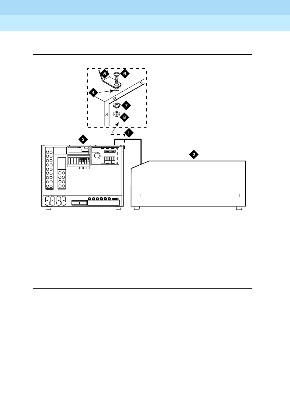
dc_rect1 RBP 051396
Figure Notes
1. DC Power Cabinet
2. To Approved Ground
3. 1 AWG (#70) (7 mm
4. Ground Discharge Bar
Figure 1-1. DC Power Cabinet Grounding
1. At the DC Power Cabinet, connect a 1 AWG (#70) (7 mm
the GROUND DISCHARGE bar. Se e Figure 1-1
.
4
2
) Wire
2
) ground wire to
2. Route the ground wire out of the cabinet and terminate it on the approved
ground.
!
CAUTION:
The approved ground must be connected using the correct gauge
wire, terminated with a listed clamp, and identified with a grounding
tag (FORM 15657NR, or equivalent).
Page 26
DEFINITY Enterprise Communication Server Release 8.2
Installation and Test for Single-Carrier Cabinets
Install and Connect the Cabinets
1
555-233-120
Connect DC Battery Cabinet Frame Ground
1
3
Issue 1
April 2000
1-8Connect Cabinet Grounds
2
dc_rect6 RBP 052996
Figure Notes
1. 6 AWG (#40) (4mm
2. DC Battery Cabinet
3. DC Power Cabinet
4. Grounding Hole in Top of Cabinets
2
) Wire
5. Terminal Lug (Part of D-18181895)
6. Pan Head Slotted Screw
7. Star Washer
8. Hex Nut
Figure 1-2. Frame Ground Wiring Between Power Cabinets
2
1. Cut a length of 6 AWG (#40) (4 mm
) wire long enough to reach between
the DC Power Cabinet and the DC Battery Cabinet. See Figure 1-2
2. Crimp a terminal lug on the each end of the wire. The terminal lugs are
furnished as part of D-181895, kit of parts.
3. At the DC Battery Cabinet, attach the 6 AWG (#40) (4 mm
2
) wire to the
frame ground mounting hole using a pan head slotted screw, star washer,
and hex nut. Tighten the screw securely.
4. Route the opposite end of the wire to the DC Power Cabinet.
5. Attach the 6 AW G (#40) (4 mm
2
) wire to the mounting hole in the top of the
cabinet. Use a pan head slotted screw, star washer, and hex nut. Tighten
the screw securely.
.
Page 27

DEFINITY Enterprise Communication Server Release 8.2
Installation and Test for Single-Carrier Cabinets
Install and Connect the Cabinets
1
555-233-120
Connect DC Power Distribution Unit Ground
j58890r1 RBP 042296
Figure Notes
Issue 1
April 2000
1-9Connect Cabinet Grounds
1. DC Power Cabinet
2. DC Power Distribution Unit
3. Ground Discharge Bar
4. 6 AWG (#40) (4 mm
2
) Wire
5. GRD Connector Terminal on DC
Power Distribution Unit
6. To Additional DC Power Di stribution
Units (If Required)
Figure 1-3. DC Power Distribution Unit Ground
2
1. Measure and cut a length of 6 AW G (#40) (4 mm
) wire long enough to
reach between the GROUND DISCHARGE bar in the DC Power Cabinet
and the GRD connector on the DC Distribution Unit. See Figure 1-3
2. At the DC Power Cabinet, connect the 6 AWG (#40) (4 mm
2
) wire to the
GROUND DISCHARGE bar.
3. Route the opposite end of the wire to the DC Power Distribution Unit and
connect the wire to the GRD connector.
4. Repeat Steps 2 and 3 for each remaining DC Power Distribution Unit.
.
Page 28

DEFINITY Enterprise Communication Server Release 8.2
Installation and Test for Single-Carrier Cabinets
Install and Connect the Cabinets
1
555-233-120
Connect Single-Carrier Cabinet Ground
On On
Off
Issue 1
April 2000
1-10Connect Cabinet Grounds
Off
5
6
1
2
1
4
On On
Off
Off
3
Figure Notes
1. 6 AWG (#40) (4 mm
2. Control Cabinet (Cabinet A)
3. Single-Point Ground Block
2
) Wire
4. To Additional Control Cabinets in Same
Room
5. DC Power Cabinet
6. Ground Discharge Bar
Figure 1-4. Single-Carrier Cabinet Ground
2
1. Cut a length of 6 AWG (#40) (4 mm
) wire long enough to reach between
the GROUND DISCHARGE bar on the DC Power Cabinet and the
single-point ground block on the Control Cabinet (bottom cabinet in Figure
1-4).
dc_rect4 RBP 032896
2. At the DC Power Cabinet, connect the wire to the GROUND DISCHARGE
bar.
3. Route the wire to Control Cabinet and connect to the single-point ground
block.
4. Repeat for each Control Cabinet in the system room (duplicated Control
Cabinet and Expansion Control Cabinet).
Page 29

DEFINITY Enterprise Communication Server Release 8.2
Installation and Test for Single-Carrier Cabinets
Install and Connect the Cabinets
1
555-233-120
Grounding AC-Powered Cabinets Only
!
CAUTION:
System grounding shall comply with the general rules for grounding
contained in Article 250 of the National Electrical Code (NEC), National Fire
Pr otection Agency (NFPA) 70, or the applicable code at the installation site.
NOTE:
Before connecting the cabinets to the approved ground, determine the
best method of grounding. See ‘‘Approved Grounds’’ on page 1-5
locate the approved ground as close to the cabinets as possible.
NOTE:
The ground plates and cabinet clips are installed later in this chapter.
Issue 1
April 2000
1-11Connect Cabinet Grounds
. Also,
1. Measure and cut a length of 6 AW G (#40) (4 mm
2
) wire long enough to
reach between the cabinet stack single-point ground block and the
approved ground. See Figure 1-5
2. At the lower left rear of the Control Cabinet (Cabinet A), connect the
6 AWG (#40) (4 mm
2
) ground wire to the cabinet stack single-point ground
.
block.
3. Run the ground wire to the approved ground and attach securely.
4. Repeat Steps 1-3 for each Expansion Control Cabinet.
NOTE:
If the Expansion Control Cabinet is remotely located from Cabinet A
(in a separate room or building), run the 6 AWG (#40) (4 mm
2
)
cabinet ground wire to an approved protective ground.
5. At Cabinet A, connect a 10 AWG (#25) (2.5 mm
ground block. The 10 AWG (#25) (2.5 mm
2
) wire to the single-point
2
) wire must be long enough to
reach the telecommunications cables at the rear of the system cabinets,
follow these cables to the Main Distribution Frame (MDF), and to terminate
at the Coupled Bonding Conductor (CBC).
The Coupled Bonding Conductor (CBC) wires are installed and terminated in
Chapter 2, ‘‘Install Telecommunications Cabling’’
.
Page 30

DEFINITY Enterprise Communication Server Release 8.2
bCJL030896
Installation and Test for Single-Carrier Cabinets
Install and Connect the Cabinets
1
555-233-120
Single-Carrier Cabinet Ground
1
Issue 1
April 2000
1-12Connect Cabinet Grounds
2
3
4
7
On
OffOnOff
5
8
Figure Notes
1. Cabinet Stack 1 Control Cabinet A
2. Circuit Breaker
3. AC Power Receptacle
4. Cabinet Stack Single-Point Ground
Block
5. 8-Foot (2.5 Meters) Power Cord
6
r781851
6. National Electrical Manufacturers
Association (NEMA) 5-15 or 5-20
Receptacle or Equivalent
2
7. 6 AWG (#40) (4 mm
) Ground Wire
to Approved Ground
8. 10 AWG (#25) (2.5 mm
2
) Wire to
Coupled Bonding Conductor
Figure 1-5. Typical AC Power and Ground Layout — Rear
Page 31

DEFINITY Enterprise Communication Server Release 8.2
Installation and Test for Single-Carrier Cabinets
Install and Connect the Cabinets
1
555-233-120
Connect AC Power
Set the Ringer Frequency
The default ringer frequency setting on the 1217A power supply for North
America is 20 Hz and the international setting can be either 20 Hz or 25 Hz. To
set the ringer frequency on the 1217A power supply:
!
CAUTION:
When adding or replacing any hardware, be sure to ground yourself against
electrostatic discharge (ESD) by wearing a grounded wrist strap.
1. Power down AUDIX and any other circuit pack that might be running an
application.
2. Power down the cabinet.
3. Release both latches on the power supply and slide the unit out of the
cabinet.
Issue 1
April 2000
1-13Connect AC Power
4. Observe the ring frequency switch label on the side of the power supply
and locate the switch on the bottom.
5. Set the ring frequency select switch to the appropriate frequency setting.
6. Slide the power supply back into the slot and ensure that both latches
snap closed.
Connect the Power Cord into the Power Receptacle
1. Provide one receptacle per Single-Carrier Cabinet.
2. Verify the circuit breakers are OFF.
3. Plug the cabinet AC power cord into the AC power receptacle on the rear
of each cabinet.
4. Plug the opposite end of each AC power cord into the appropriate AC
power receptacle in the equipment room.
NOTE:
Loop the excess cord and tie wrap it to the back cover to prevent
accidental unplugging.
Page 32

DEFINITY Enterprise Communication Server Release 8.2
Installation and Test for Single-Carrier Cabinets
Install and Connect the Cabinets
1
555-233-120
Connect DC Power
The following procedures apply to both the Processor Port Networks (PPN) and
Expansion Port Networks (EPN).
DC Power Connections
A 30 foot (9 m) cable connects to each cabinet. A special connector on one end
of the cable is plugged into the cabinet power connector. The cable must be cut
to length and terminated inside the J58890R DC Power Cabinet.
Each rectifier assembly can supply up to 50 Amps of DC current. A minimum of
two rectifiers are installed in each DC Power Cabinet to supply a total of 100
Amps. A third rectifier assembly can be installed and is used as a backup (N+1).
Each Single-Carrier Cabinet can pull up to 18 Amps. Up to three DC Power
Cabinets can be stacked to supply power to Single-Carrier Cabinet stacks.
Issue 1
April 2000
1-14Connect DC Power
Figure 1-6
without a J58890CG DC Power Distribution Unit. The J58890CG is required if the
distance between the DC Power Cabinet(s) is greater than 30 feet (9 m). Figure
1-7 shows a typical power and ground layout for a DC-powered system
containing a DC power distribution unit.
shows a typical power and ground layout for a DC-powered system
Connect AC Power to DC Power Cabinet
1. Ensure the associated circuit breakers at the AC power panel are OFF.
2. Have an electrician connect AC power leads to the rectifiers using the
instructions provided with the rectifiers in the DC Power Cabinet. Each
rectifier should have its own branch circuit. Terminate leads on the AC
INPUT terminal block of each rectifier.
!
CAUTION:
Power is present in the cabinet even if the AC power cable is
unplugged. Turn off the main circuit breaker on the front of the
cabinet when procedures require ALL power to be removed from the
cabinet.
Page 33

DEFINITY Enterprise Communication Server Release 8.2
Installation and Test for Single-Carrier Cabinets
Install and Connect the Cabinets
1
555-233-120
DC Power Connections
Issue 1
April 2000
1-15Connect DC Power
Figure Notes
1. System Cabinet Stack
2. DC Power Cabinet
3. White Wires
4. Green Ground Wires and Black
Wires Connect to the -48 VDC
Return Bus
5. -48 VDC Bus
6. Connect White Wires to Circuit
Breakers
7. DC Power Cable (H600-436, G1) to
Power Connector on Each Cabinet. Cut
to Length and Crimp a Ring Terminal
Onto Each Wire
8. 30 Feet (9 m) Maximum
9. Route Cables Through Sliding Door
10. Circuit Breaker
11. Supplied #10-32 Screw, #10 S tar
Washer, and #10-32 Hex Nut
12. Inset Showing DC Power Connector
(Male)
Figure 1-6. Typical DC Power Connections
Page 34

DEFINITY Enterprise Communication Server Release 8.2
Installation and Test for Single-Carrier Cabinets
Install and Connect the Cabinets
1
555-233-120
DC Power Connections with DC Distribution Unit
A 10 foot (3 meter) power cord is equipped with the appropriate connectors. In
the configuration shown in Figure 1-7
Distribution Unit associated with it.
, each cabinet stack has a DC Power
Issue 1
April 2000
1-16Connect DC Power
Figure Notes
1. System Cabinet Stack
2. DC Power Cabinet
3. DC Power Distribution Unit (Position
to the Right of the Cabinet Stack)
4. White Wire (Connect to Circuit
Breaker). See Inset.
5. Green Ground Wire and Black Wire
Connect to the -48 VDC Return Bus
6. -48 VDC Bus
7. Inset
8. 12 Inches (30.5 cm) From Floor to
9. DC Power Cable to Power
Connector on Each Cabinet
10. DC Power Distribution Unit Power
Cord (Route to Rear of DC Power
Cabinet)
11. Route P ower Cord Through Sliding
Door
12. Circ uit Breaker
13. Supplied #10-32 Screw, #10 Star
Washer, and #10-32 Hex Nut
14. Inset Showing DC Power Connector
(Male)
DC Power Distribution Unit
Figure 1-7. Connections Using DC Power Distribution Unit
Page 35

DEFINITY Enterprise Communication Server Release 8.2
Installation and Test for Single-Carrier Cabinets
Install and Connect the Cabinets
1
555-233-120
Stacking DC Power Cabinets
Up to three DC P ower Cabinets can be stacked to supply power to Single-Carrier
Cabi net sta cks. See Figure 1-8
.
Issue 1
April 2000
1-17Connect DC Power
Figure Notes
1. DC Power Cabinet Stack
2. DC Power Cables Daisy Chained
Between DC Power Cabinets
3. Connect to -48 VDC Bus
4. Connect to -48 VDC Return Bus
5. Inset Applies to -48 VDC and -48
VDC Return Buses in All Three DC
Power Cabinets
Figure 1-8. DC Power Cabinet Stack — Rear
pwrdist4RBP 052896
Page 36

DEFINITY Enterprise Communication Server Release 8.2
Installation and Test for Single-Carrier Cabinets
Install and Connect the Cabinets
1
555-233-120
Connect Battery Cabinet
Figure 1-9 shows typical connections from the DC Battery Cabinet to the DC
Power Cabinet.
Issue 1
April 2000
1-18Connect Battery Cabinet
pwrdist5 RBP 052896
Figure Notes
1. DC Power Cabinet
2. Connect Red DC Power Cable to
-48 VDC Return Bus
3. Connect Black DC Power Cable to
4. Inset Applies to -48 VDC Buses an d
-48 VDC Return Buses
5. Battery Cabinet
6. DC Power Cables (Red and Black)
-48 VDC Bus
Figure 1-9. DC Battery to DC Power Cabinet Connections
!
CAUTION:
Power is present in the cabinet even if the AC power cable is unplugged.
Turn off the main circuit breaker on the front of the cabinet when procedures
require ALL power to be removed from the cabinet.
Page 37

DEFINITY Enterprise Communication Server Release 8.2
Installation and Test for Single-Carrier Cabinets
Install and Connect the Cabinets
1
555-233-120
Connect Optional Battery Leads
To prevent the internal batteries from discharging, the Control Cabinet is shipped
with the battery leads disconnected.
1
2
Issue 1
April 2000
1-19Connect Optional Battery Leads
3
4
4_3 LJK 031096
Figure Notes
1. Battery
2. Battery Lead Connector
3. Circuit Breakers (Located Between
Plates)
4. Cabinet Single-Point Ground Block
Figure 1-10. Control Cabinet Battery Location — Right Side
1. Set the circuit breakers OFF. See Figure 1-10
.
2. Connect the battery leads. The battery is near the top of the carrier toward
the front-right. The battery leads are located next to the battery and are
accessible from the front of the cabinet.
Page 38

DEFINITY Enterprise Communication Server Release 8.2
Installation and Test for Single-Carrier Cabinets
Install and Connect the Cabinets
1
555-233-120
Connect AC Power to Stratum 3 Clock Cabinet
The clock cabinet requires a 120 VAC, 15 Amp receptacle. The green wire
ground provided by the receptacle is sufficient. The clock cabinet does not
require a ground connection back to the single-point ground.
Check and Connect Commercial AC Power
Before powering up the system, check the AC power using a KS-20599 digital
voltmeter (DVM) (or equivalent).
1. Set the DVM to the 250 volt range.
2. Carefully measure the voltage between the hot and neutral side of the
receptacle. The neutral wire is white, the hot wire is black.
3. Verify the meter reads 106 to 128 V AC. If not, have a qualified electrician
correct the problem.
Issue 1
April 2000
1-20Connect AC Power to Stratum 3 Clock Cabinet
4. Measure the voltage between the neutral and ground side of the
receptacle. The ground wire is green.
5. Verify the meter reads 0 VAC. If not, have a qualified electrician correct the
problem.
6. Set all cabinet power modules OFF. Plug the AC power cable into the
receptacle.
Connect DC Power and Ground to Stratum 3 Clock Cabinet
The clock cabinet should be powered from the same DC power plant as the
DEFINITY System. The clock cabinet must be grounded to the DC power plant.
Connect Clock Cabinet Grounding
1. Measure and cut a 6 AWG (#40) (4 mm2) wire long enough to reach from
the clock cabinet to the ground discharge bar in the DC power plant.
2. Insert one end of the wire into the ground lug on the clock cabinet and
tighten the screw.
3. Attach the lug to the receptacle cover. Be sure the lug and cabinet ground
wires connect to separate screws on the receptacle cover.
4. Route the ground wire to the DC power plant and connect to DISCH GRD
in the cabinet.
Page 39

DEFINITY Enterprise Communication Server Release 8.2
Installation and Test for Single-Carrier Cabinets
Install and Connect the Cabinets
1
555-233-120
Connect Stratum 3 Clock DC Power
1. Set the clock cabinet circuit breaker at the DC power plant OFF.
2. At the clock cabinet, connect a 6 AWG (#40) (4 mm
-48V terminal on the terminal strip.
3. At the clock cabinet, connect a 6 AWG (#40) (4 mm
terminal on the terminal strip.
4. Route the wires out of the cabinet and to the DC power plant.
5. At the DC power plant, connect the -48V wire to the DC OUTPUT circuit
breaker.
6. At the DC power plant, connect the -48VRTN wire to the DISCH GRD bar.
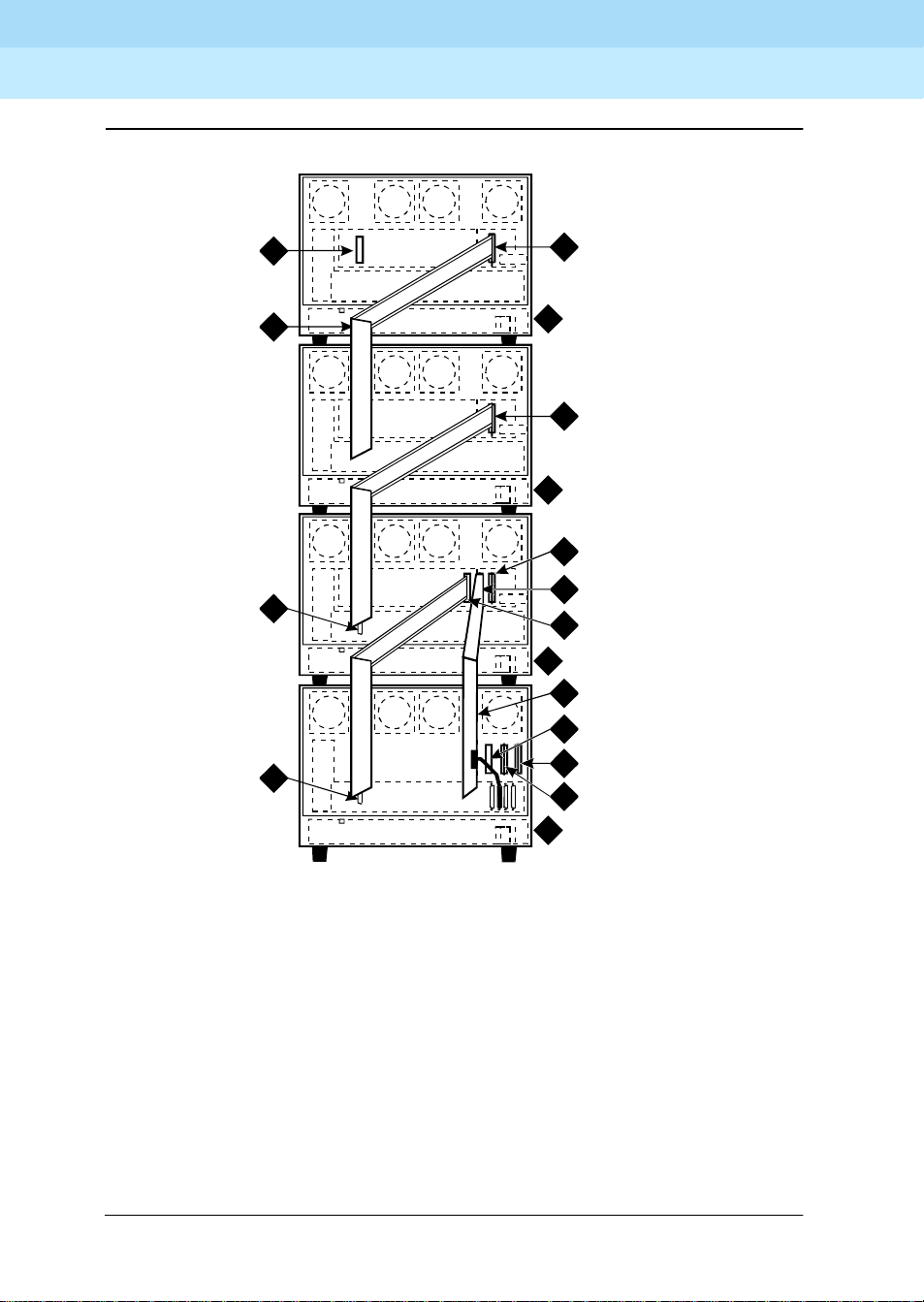
Connect Time Division Multiplexing Bus Cables
If the cabinet stack contains only one Single-Carrier Cabinet, skip this section
and proceed to ‘‘Verify Port Cabinet Address Plugs’’ on page 1-26
Issue 1
April 2000
2
) ground wire to the
2
) wire to the -48VRTN
.
1-21Connect Time Division Multiplexing Bus Cables
Locate the white fabric-covered Time Division Multiplexing (TDM) bus cable on
the rear of the cabinets.
Standard Reliability Processor Port Network
One cabinet stack:
1. Remove the Time Division Multiplexing (TDM) Bus Terminator (AHF110)
from Slot 18 of the Control Cabinet (Processor Port Network (PPN)) and
move it to Slot 17 on the top Port Cabinet. See Figure 1-11
2. Connect the supplied Time Division Multiplexing (TDM) Bus Cables
(WP-91716 L3) as shown in Figure 1-11
.
.
Page 40

DEFINITY Enterprise Communication Server Release 8.2
Installation and Test for Single-Carrier Cabinets
Install and Connect the Cabinets
1
555-233-120
High or Critical Reliability Processor Port Network
Two cabinet stacks:
1. Remove the Time Division Multiplexing (TDM) Bus Terminator from Slot 18
of Control Cabinet A (Pr ocessor Port Network (PP N)) and move it to Slot 18
of Control Cabinet B. See Figure 1-12
2. Connect the supplied Time Division Multiplexing (TDM) Bus Cables
(WP-91716 L3) from Cabinet A to Cabinet B as shown.
High or Critical Reliability Processor Port Network
Three cabinet stacks:
1. Remove the Time Division Multiplexing (TDM) Bus Terminator from Slot 18
of Control Cabinet A (Pr ocessor Port Network (PP N)) and move it to Slot 17
on the top port cabinet. See Figure 1-13
Issue 1
April 2000
1-22Connect Time Division Multiplexing Bus Cables
.
.
2. Connect the supplied TDM Bus Cables (WP-91716 L3) as shown.
Expansion Port Network (All Reliability Options)
1. Remove the TDM Bus Terminator from Slot 18 of Control Cabinet A (PPN)
and move it to Slot 17 on the top port cabinet. See Figure 1-12
2. Connect the supplied TDM Bus Cables (WP-91716 L3) as shown.
.
Page 41

DEFINITY Enterprise Communication Server Release 8.2
Installation and Test for Single-Carrier Cabinets
Install and Connect the Cabinets
1
555-233-120
Issue 1
April 2000
1-23Connect Time Division Multiplexing Bus Cables
1
3
3
3
7
2
4
2
4
2
4
6
5
tdm_cab2 CJ L 030696
Figure Notes
1. AHF110 TDM Bus Terminator (Slot
17)
2. TDM/Local Area Network
(TDM/LAN) Pinfield (Slot 00)
3. TDM Bus Cable WP-91716 L3
4. Port Cabinet (Standard Reliability)
5. Control Cabinet A Position
6. AHF110 TDM Bus Terminator (Slot
03)
7. Slot 18
Figure 1-11. Connections for Standard Reliability Systems
Page 42
DEFINITY Enterprise Communication Server Release 8.2
Installation and Test for Single-Carrier Cabinets
Install and Connect the Cabinets
1
555-233-120
Issue 1
April 2000
1-24Connect Time Division Multiplexing Bus Cables
1
3
7
7
2
4
2
4
9
10
2
11
8
6
9
10
5
tdm_cab3 CJL 053096
Figure Notes
1. AHF110 TDM Bus Terminator (Slot 17)
2. TDM/Local Area Network (TDM/LAN)
Pinfield (Slot 00)
3. TDM bus Cable (WP-91716 L3)
4. Port Cabinet
5. Control Cabinet A Position
6. AHF110 TDM Bus Terminator (Slot 01)
7. Slot 18
8. Inter-Cabinet Cables (ICC) A, B
and C (H600-248-G1)
9. Inter-Cabinet Cable (ICC) A
10. Inter-Cabinet Cable (ICC) B
11. Duplicated Control Cabinet B
Position
Figure 1-12. Connections for High or Critical Reliability Systems
Page 43

DEFINITY Enterprise Communication Server Release 8.2
Installation and Test for Single-Carrier Cabinets
Install and Connect the Cabinets
1
555-233-120
Issue 1
April 2000
1-25Connect Time Division Multiplexing Bus Cables
1
3
3
3
7
2
4
2
4
8
2
9
5
8
6
tdm_cab4 CJL 053096
Figure Notes
1. AHF110 TDM Bus Terminator (Slot
17)
2. TDM/Local Area Network
(TDM/LAN) Pinfield (Slot 00)
3. TDM bus Cable (WP-91716 L3)
4. Port Cabinet
5. Control Cabinet A Position
6. AHF110 TDM Bus Terminator (Slot
03)
7. Slot 18
8. Inter-Cabinet Cables (ICC) B and C
(H600-259-G1)
9. Duplicated Control Cabinet B
Position
Figure 1-13. Connections for High or Critical Reliability Systems
Page 44
DEFINITY Enterprise Communication Server Release 8.2
Installation and Test for Single-Carrier Cabinets
Install and Connect the Cabinets
1
555-233-120
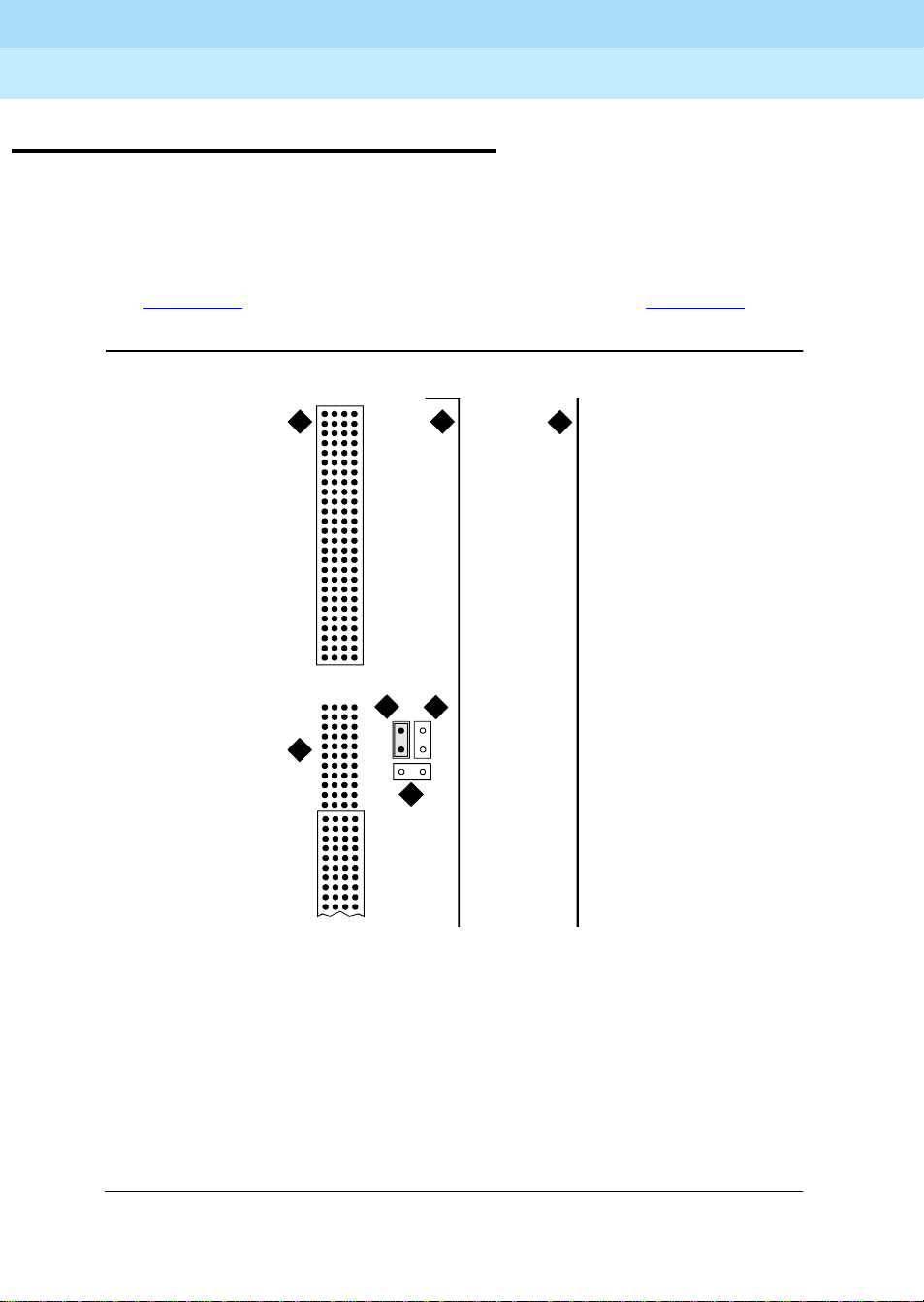
Verify Port Cabinet Address Plugs
The address plug is a jumper field on port cabi nets only. The address plug is
located on the far right hand side of the backplane, to the right of slot 00.
A group of six pins is labeled for the cabinet (carrier) jumper connections. V erify
the address plug for
See Figure 1-14
each
port carrier is in the correct location for that carrier.
. The factory default setting is “B” (Callout 2 in Figure 1-14).
Issue 1
April 2000
1-26Verify Port Cabinet Address Plugs
6
7
4
1
2
3
add_plug CJL 050906
5
Figure Notes
1. Address Plug (Shown Set to Carrier D)
2. Carrier B Jumper Location (Default)
3. Carrier C Ju mper Location
5. Right Edge of Cabinet
6. Backplane Slot 00
7. To Connector Panel
4. Right Edge of Backplane
Figure 1-14. Port Cabinet Address Plug Location — Cabinet Rear
Page 45
DEFINITY Enterprise Communication Server Release 8.2
Installation and Test for Single-Carrier Cabinets
Install and Connect the Cabinets
1
555-233-120
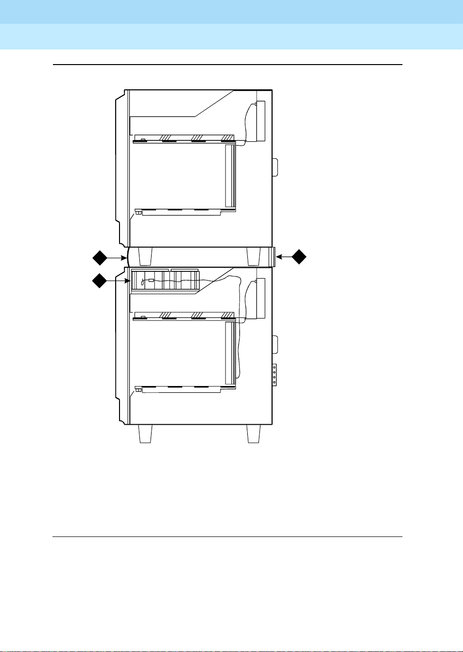
Install Rear Panels
Issue 1
April 2000
1-27Install Rear Panels
3
1
2
Figure Notes
1. Cabinet in A Position (No Ground Plate is
Installed on an Unstacked Cabinet)
2. Rear Ground Plate (Attached Between Stacked
Cabinets)
Figure 1-15. Rear Panel Screw Locations
4 4
grnd_plt CJL 030696
3. Cabinet in B Position
4. Screws to Loosen
1. Install the rear panels and loosely thread each screw. See Figure 1-15
2. For
unstacked
For a
cabinets, tighten the screws securely.
stack
of cabinets, allo w the screws labeled Callout 4 to r emain loose .
These screws are tightened when the ground plates are installed.
3. Be sure the Time Division Multiplexing (TDM) bus cables and the
Inter-Cabinet Cables (ICC) are not pinched by the panels. Also be sure
the cables are routed through the channels provided on the rear panels.
.
Page 46

DEFINITY Enterprise Communication Server Release 8.2
Installation and Test for Single-Carrier Cabinets
Install and Connect the Cabinets
1
555-233-120
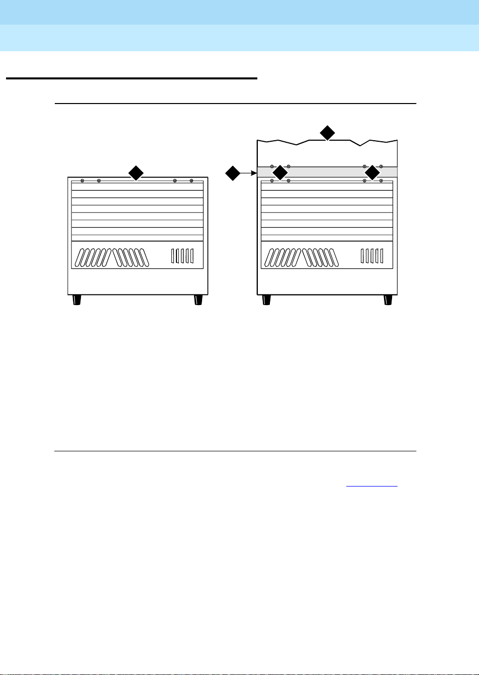
Install Ground Plates
Ground plates are installed between stacked cabinets, provide the ground
connection between cabinets, provide radio frequency (RF) radiation protection,
and help stabilize the cabinets.
Install Rear Ground Plates (Systems with Earthquake Protection)
1. Loosen the four screws at the bottom of the top cabinet and at the top of
the cabinet underneath the top cabinet. See Figure 1-15
2. Align the mounting holes in the rear ground plate over the bottom screws
in the top cabinet. See Figure 1-16
3. Align the mounting holes in the ground plate with the four holes at the top
of the cabinet below the top cabinet. Slide the mounting plate down to
seat on the screws.
4. Check all Time Division Multiplexing (TDM) bus cables and the Inter
Cabinet Cables (ICC) to be sure they are not pinched by the plates.
Issue 1
April 2000
1-28Install Ground Plates
.
.
5. Repeat Steps 1-3 until the rear ground plates are installed between all
stacked cabinets.
6. Do not tighten the screws yet.
Install Front Ground Plates (Systems with Radiation Shielding and Earthquake Protection)
Use the front ground plate instead of the cabinet clip to attach the cabinets to
each other. Use one front ground plate between two
1. At the front of the cabinets, align the holes in the top of the front ground
plate with the holes at the bottom of the upper cabinet, and insert the four
screws. Do not tighten the screws yet. See Figure 1-16
2. At the front of the cabinets, align the holes in the bottom of the front
ground plate with the holes at the top of the lower cabinet. Insert the four
supplied #12-24 x 1/2-inch (1.27 cm) thread-forming screws. Do not
tighten the screws yet.
3. Repeat Steps 1 and 2 until all stacked cabinets are fastened together.
4. Tighten all screws securely.
stacked
cabinets.
.
Page 47
DEFINITY Enterprise Communication Server Release 8.2
Installation and Test for Single-Carrier Cabinets
Install and Connect the Cabinets
1
555-233-120
Issue 1
April 2000
1-29Install Ground Plates
1
2
Figure Notes
1. Front Ground Plate or Cabinet Clip
2. Battery
3
grdpltec LJK 031096
3. Rear Ground Plate
Figure 1-16. Rear Ground Plate and Front Plate or Cabinet Clip — Side View
Page 48

DEFINITY Enterprise Communication Server Release 8.2
Installation and Test for Single-Carrier Cabinets
Install and Connect the Cabinets
1
555-233-120
Install Cabinet Clips (Systems without Earthquake Protection)
A cabinet clip is required between each pair of stacked cabinets.
At the front of the cabinets, install a cabinet clip between each pair of cabinets
by hooking the clip into the slot of the upper cabinet and snapping the straight
leg of the clip into the slot on the lower cabinet. See Figure 1-17
Issue 1
April 2000
1-30Install Ground Plates
.
Figure Notes
1. Control Cabinet
2. Port Cabinet or Duplicated Control Cabinet
3. Port Cabinet
Figure 1-17. Location of Cabinet Clips
4. Port Cabinet
5. Cabinet Clips
Page 49

DEFINITY Enterprise Communication Server Release 8.2
Installation and Test for Single-Carrier Cabinets
Install and Connect the Cabinets
1
555-233-120
Connect System Cables
Inter-Cabinet Cables (High or Critical Reliability)
1. Connect the cables for critical reliability Expansion Port Networks (EPNs)
as shown in Figure 1-12
2. Connect the cables for high or critical reliability Processor Port Networks
(PPNs) as shown in Figure 1-13
Table 1-1. Inter-Cabinet Cable Connections
Cabinet Carrier Connection Carrier Connection
Processor Port
Network (PPN)
Expansion Port
Network (EPN)
J58890L (ICC) B J58890M (ICC) B
J58890N (ICC) A J58890H (ICC) A
and in Table 1-1 below.
.
From Cabinet A To Cabinet B
(ICC) C (ICC) C
(ICC) B (ICC) B
Issue 1
April 2000
1-31Connect System Cables
Fiber Optic Cables
The fiber optic cables are connected to the Main Distribution Frame (MDF) in
Chapter 2, ‘‘Install Telecommunications Cabling’’
‘‘Connecting and Handling Fiber Optic Cables’’ for information about connecting
to optical cross-connect hardware and routing through lightguide equipment.
The DEFINITY ECS may contain a Class 1 LASER device if single-mode fiber
optic cable is connected to a remote Expansion Port Network (EPN). The LASER
device operates within the following parameters:
Maximum Power Output: -5 dBm
Wavelength: 1310 nm
Mode Field Diameter: 8.8 microns
CLASS 1 LASER PRODUCT
IEC 825 1993
!
CAUTION:
Use of controls or adjustments or performance of procedures other than
those specified herein may result in hazardous radiation exposure.
Contact your Lucent Technologies representative for more information.
. Refer to Appendix B,
Page 50

DEFINITY Enterprise Communication Server Release 8.2
Installation and Test for Single-Carrier Cabinets
Install and Connect the Cabinets
1
555-233-120
Fiber Optic Cable Connections
The Customer Service Document (CSD) provides an “Inter-Cabinet Cable
Running List.” Each row on the list represents a cable connection. Use the
running list to determine where to connect each fiber optic cable.
Multi-Mode Fiber Optic Connections
The following components are used in multi-mode fiber optic connections:
■ Expansion Interface (EI) circuit packs in port slots in cabinet carriers
■ Cables from each interface circuit pack to each port slot connector
■ The 9823A lightwave transceiver transmits up to 4,900 feet (1.5 km). The
9823B lightwave transceiver transmits up to 25,000 feet (7.6 km).
■ Multi-mode fiber optic cable consists of two separate 62.5 micron
diameter fiber optic cables or 50 micron diameter fiber optic cables.
Single-Mode Fiber Optic Connections
The following components are used in single-mode fiber optic connections:
Issue 1
April 2000
1-32Connect System Cables
■ Expansion Interface (EI) circuit packs in port slots in cabinet carriers
■ Cables from each interface circuit pack to each port slot connector
■ The 300A lightwave transceivers transmits light up to 115,000 feet (35
km). Fiber loss must be less than 17dB. Saturation may occur if distances
are short; attenuators may be required if the total loss on the fiber link is
less than 10dBm. An Optical Time Domain Reflectometer (OTDR) test is
recommended to determine specific fiber op t ic hardware requirements .
■ Single-mode fiber optic cable consists of two separate 8 to 10 micron core
cables.
NOTE:
5 and 10dB attenuators are available. Contact your Lucent
Technologies representative for more information.
Page 51

DEFINITY Enterprise Communication Server Release 8.2
Installation and Test for Single-Carrier Cabinets
Install and Connect the Cabinets
1
555-233-120
Recommended Cable Routing
1. Route the fiber op t ic cable up toward the top of the cabinet. The exces s
cable should be looped and draped from the B25A cable clamp on the
top ground plate in the stack. See Figure 1-18
2. Dress the cable by tie wrapping it to the outside of the B25A cable clamp.
!
CAUTION:
Do not route fiber optic cables and the B25A cables together.
4 4
2
Issue 1
April 2000
1-33Connect System Cables
.
1
4 4
4 4
5 5
Figure Notes
1.Supplied B25A Cables
2. Loop and Drape Excess Fiber
Optic Cable
3
3. Fiber Optic Cable Sheath
4. Port Cabinet
5. Control Cabinet
Figure 1-18. Single-Carrier Cabinet Fiber Routing
Page 52

DEFINITY Enterprise Communication Server Release 8.2
Installation and Test for Single-Carrier Cabinets
Install and Connect the Cabinets
1
555-233-120
Standard Reliability Fiber Connections
Connect and route the fiber optic cable as shown in the cable running list. See
Figure 1-19
18 17 1615 14 13 12 11 10 9 8 7 6 5 4 3 2 1 18 17 1615 14 13 12 11 10 9 8 7 6 5 4 3 2 1 18 17 16 15 14 13 12 1110 9 8 7 6 5 4 3 2 1
for a sample cable routing.
Issue 1
April 2000
1-34Connect System Cables
18 17 1615 14 13 12 11 10 9 8 7 6 5 4 3 2 1
18 17 1615 14 13 12 11 10 9 8 7 6 5 4 3 2 1
1615 14 13 12 11 10 9 8 7 6 5 4 3 2 1
Figure Notes
1. Control Cabinet
2. Port Cabinet
3. Expansion Control Cabinet
Terminal
18 17 1615 14 13 12 11 10 9 8 7 6 5 4 3 2 1 18 17 16 15 14 13 12 11 10 9 8 7 6 5 4 3 2 1
2
18 17 1615 14 13 12 11 10 9 8 7 6 5 4 3 2 1 18 17 16 15 14 13 12 11 10 9 8 7 6 5 4 3 2 1
3
18 17 1615 14 13 12 11 10 9 8 7 6 5 4 3 2 1 18 17 16 15 14 13 12 11 10 9 8 7 6 5 4 3 2 1
stndard LJK 032896
4. Cabinet Stack 1
5. Cabinet Stack 2
6. Cabinet Stack 3
Figure 1-19. Connections to Standard Reliability Systems
Page 53

DEFINITY Enterprise Communication Server Release 8.2
Installation and Test for Single-Carrier Cabinets
Install and Connect the Cabinets
1
555-233-120
High Reliability Fiber Connections
Connect and route the fiber optic cable as shown in the cable running list. See
Figure 1-20
18 17 16 15 14 13 12 1110 9 8 7 6 5 4 3 2 1 18 17 16 15 14 13 12 11 10 9 8 7 6 5 4 3 2 1 18 17 16 15 14 13 12 11 10 9 8 7 6 5 4 3 2 1
18 17 16 15 14 13 12 1110 9 8 7 6 5 4 3 2 1 18 17 16 15 14 13 12 11 10 9 8 7 6 5 4 3 2 1 18 17 16 15 14 13 12 11 10 9 8 7 6 5 4 3 2 1
for a sample cable routing.
Issue 1
April 2000
1-35Connect System Cables
1615 14 13 12 1110 9 8 7 6 5 4 3 2 1
1615 14 13 12 1110 9 8 7 6 5 4 3 2 1
Ter m ina l
Ter m ina l
18 17 16 15 14 13 12 1110 9 8 7 6 5 4 3 2 1 18 17 16 15 14 13 12 11 10 9 8 7 6 5 4 3 2 1
18 17 16 15 14 13 12 1110 9 8 7 6 5 4 3 2 1 18 17 16 15 14 13 12 11 10 9 8 7 6 5 4 3 2 1
Figure Notes
1. Control Cabinet
2. Duplicate Control Cabinet
3. Port Cabinet
5. Cabinet Stack 1
6. Cabinet Stack 2
7. Cabinet Stack 3
4. Expansion Control Cabinet
Figure 1-20. Connections to High Reliability Systems
high LJK 032896
Page 54

DEFINITY Enterprise Communication Server Release 8.2
6
Installation and Test for Single-Carrier Cabinets
Install and Connect the Cabinets
1
555-233-120
Critical Reliability Fiber Connections
Connect and route the fiber optic cable as shown in the cable running list. See
Figure 1-21
18 17 16 15 14 13 12 1110 9 8 7 6 5 4 3 2 1 18 17 16 15 14 13 12 11 10 9 8 7 6 5 4 3 2 1 18 17 16 15 14 13 12 11 10 9 8 7 6 5 4 3 2 1
18 17 16 15 14 13 12 1110 9 8 7 6 5 4 3 2 1 18 17 16 15 14 13 12 11 10 9 8 7 6 5 4 3 2 1 18 17 16 15 14 13 12 11 10 9 8 7 6 5 4 3 2 1
for a sample cable routing.
Issue 1
April 2000
1-36Connect System Cables
1615 14 13 12 1110 9 8 7 6 5 4 3 2 1
1615 14 13 12 1110 9 8 7 6 5 4 3 2 1
Ter m ina l
Ter m ina l
18 17 16 15 14 13 12 1110 9 8 7 6 5 4 3 2 1 18 17 16 15 14 13 12 11 10 9 8 7 6 5 4 3 2 1
18 17 16 15 14 13 12 1110 9 8 7 6 5 4 3 2 1 18 17 16 15 14 13 12 1110 9 8 7 6 5 4 3 2 1
Figure Notes
1. Control Cabinet
2. Duplicate Control Cabinet
3. Port Cabinet
5. Cabinet Stack 1
6. Cabinet Stack 2
7. Cabinet Stack 3
4. Expansion Control Cabinet
Figure 1-21. Connections to Critical Reliability Systems
critical LJK 03289
Page 55

DEFINITY Enterprise Communication Server Release 8.2
Installation and Test for Single-Carrier Cabinets
Install and Connect the Cabinets
1
555-233-120
Install Earthquake Protection
Earthquake protection only installs on Single-Carrier Cabinets.
Issue 1
April 2000
1-37Install Earthquake Protection
1
3
4
Figure Notes
1. #12-24x1/2-inch Thread Forming
Screw
2. Control Cabinet
3. Front Mounting Angle
2
5
6
7
r781854aCJL 030896
4. Hex Head Bolt
5. Nylon Insulating Washer
6. Concrete Floor
7. Concrete Floor Anchor
Figure 1-22. Front Mounting Angle Location
1. Position the Control Cabinet (J58890L) in the position it is to occupy when
the installation is complete. Be sure the cabinet is level.
2. Using a pencil or marker and using the Front Mounting Angle as a
template, mark the locations of the two floor mounting holes.
3. Move the cabinet out of the way and drill a hole 0.5-inch (1.3 cm) in
diameter and 1.5 inches (3.8 cm) deep at the locations marked in Step 2.
4. Insert a concrete floor anchor (STARR part number 3425) into each hole.
Page 56

DEFINITY Enterprise Communication Server Release 8.2
Installation and Test for Single-Carrier Cabinets
Install and Connect the Cabinets
1
555-233-120
5. Secure the Front Mounting Angle to the floor using the short hex head
bolts provided.
6. Move the cabinet back into place.
7. At the rear of the cabinet, remove the two hole plugs from the bottom of
the cabinet. See Figure 1-23
.
8. Insert a pencil or marker through the holes in the bottom of the cabinet
and mark the floor directly beneath each hole.
9. Move the cabinet out of the way and drill a hole 0.5-inch (1.27 cm) in
diameter and 1.5 inches (3.8 cm) deep at the locations marked in Step 8.
10. Insert a concrete floor anchor (STARR part number 3425) into each hole.
11. Move the cabinet back into place and align with the Front Mounting Angle.
12. Attach the cabinet to the Front Mounting Angle using the four supplied
#12-24 x 1/2-inch (1.27 cm) thread-forming screws. See Figure 1-22
Issue 1
April 2000
1-38Install Earthquake Protection
.
Page 57

DEFINITY Enterprise Communication Server Release 8.2
Installation and Test for Single-Carrier Cabinets
Install and Connect the Cabinets
1
1
On
OffOnOff
2
3
555-233-120
Issue 1
April 2000
1-39Install Earthquake Protection
4
5
8
7
6
r781851a CJL 030796
Figure Notes
1. Cabinet
2. Nylon Insulating Washer (2 Required)
3. Long Hex Head Bolt (2 Required)
4. Stiffener
5. Cabinet Foot
6. Floor Plugs (Remove)
7. Concrete Floor Anchor
8. Concrete Floor
Figure 1-23. Cabinet Earthquake Mounting — Rear View
13. Lay the supplied Stiffener on the bottom rear of the cabinet and align with
the holes in the bottom of the cabinet. See Figure 1-23
.
14. Slide a nylon washer onto each of the two supplied long hex head bolts.
15. Insert the bolts through the Stiffener and thread into the concrete floor
anchor. Tighten securely.
NOTE:
If critical reliability is installed, the Expansion Control Cabinet sets on
the floor, next to Control Cabinet A. Repeat the above procedures.
Page 58

DEFINITY Enterprise Communication Server Release 8.2
Installation and Test for Single-Carrier Cabinets
Install and Connect the Cabinets
1
555-233-120
Issue 1
April 2000
1-40Install Earthquake Protection
Page 59

DEFINITY Enterprise Communication Server Release 8.2
Installation and Test for Single-Carrier Cabinets
Install Telecommunications Cabling
2
555-233-120
Install Telecommunications Cabling
Equipment Room Hardware
Issue 1
April 2000
2-1Equipment Room Hardware
2
SYSTIMAX 110-type hardware is used for the Main Distribution Frame (MDF).
110-type hardware is available in two basic types: the 110A and 110P. T he 110A
requires less wall space than the 110P. The 110P includes horizontal and vertical
cable troughs for managing cross-connect cables. The system is connected to
the MDF with the supplied B25A male to female 25-pair cables. The cables are
provided in 10-foot (3 m) and 15-foot (4.5 m) lengths.
Refer to
Distribution Field Design
Figure 2-1
connecting system cabinets and satellite closets to the MDF. The figure shows
the cross-connections for one example station circuit.
DEFINITY Communications System Generic 1 and Generic 3 Main
for more information.
shows a detailed example of Single-Carrier Cabinet cables
Page 60
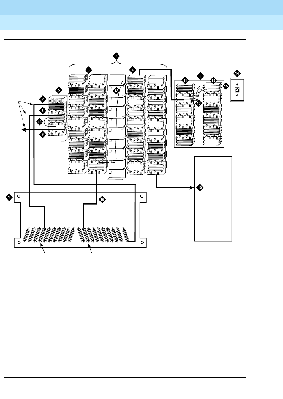
DEFINITY Enterprise Communication Server Release 8.2
Installation and Test for Single-Carrier Cabinets
Install Telecommunications Cabling
2
555-233-120
Issue 1
April 2000
2-2Equipment Room Hardware
25-Pair
Cable
Network
Intrface
YellowField
To
25-Pair
Cable
25-Pair
Cable
16171819 15 14 13 12 11 10 09 08 07 06 05 04 03 02 01 AUX
25-Pair
Cable
25-Pair
Cable
T runk Circuit Pack
Line Circuit Pack
Figure Notes
1. Rear of Port Cabinet
2. Main Distribution Frame (MDF)
3. Port Distribution Field (Purple Field)
4. Station Distribution Field (White Field)
5. Trunk/Auxiliary Field
6. Purple Field
7. Yellow Field
8. Green Field
Figure 2-1. Example MDF Connections
0016_0 RBP 052396
9. Satellite Closet
10. Auxiliary Cabinet (Yellow Field)
11. White Field
12. Blue Field
13. Cross-Connect Jumpers
14. 103A or Modular Wall Jack
15. 4-Pair Line Cord
16. To Line Circuit Pack
Page 61

DEFINITY Enterprise Communication Server Release 8.2
Installation and Test for Single-Carrier Cabinets
Install Telecommunications Cabling
2
555-233-120
Cross-Connect Fields
Each Main Distribution Frame (MDF) contains a trunk/auxiliary field and a
distribution field. The trunk/auxiliary field contains three cross-connect areas:
1.
The green field
Office (CO) and provides the terminals to cross-connect the leads to the
purple or yellow fields as required. A single row of the 110-type terminal
block can terminate twenty-four 1-pair, eight 3-pair, or twelve 2-pair
trunks.
2.
The purple field
WP-90929, List 1 or 3 concentrator cables. Also, 25-pair cables can be
used to terminate trunk circuits from the system with each trunk circuit
pack connecting to one 25-pair row of the 110-type terminal block. Each
terminal block row can terminate twenty-four 1-pair, eight 3-pair, or twelve
2-pair trunks.
3.
The yellow field
leads from the system, such as alarm monitors, emergency transfer relay
power, and attendant console power. This field is used for emergency
transfer wiring, paging equipment, music sources, and so forth.
terminates the network interface leads from the Central
terminates the trunk circuits from the system with
provides cross-connect terminals for all miscellaneous
Issue 1
April 2000
2-3Equipment Room Hardware
The distribution field contains four cross-connect areas:
1.
The purple field
(port field) terminates 25-pair cables from the system.
Each line circuit pack connects to one 25-pair row of the 110-type terminal
block. One 25-pair cable is required for each line circuit pack.
NOTE:
The 16-port analog line circuit pack requires an adapter cable to
connect from one connector on the system to two 25-pair connectors
on a terminal block. Two MET circuit packs require a concentrator
cable to connect from two connectors on the system to one 25-pair
connector on a terminal block.
2.
The yellow field
(auxiliary field) terminates all 25-pair cables from the
auxiliary cabinet and the Processor Interface. The yellow field is located in
the lower right-hand corner of the distribution field.
3.
The white field
(station field) terminates the station wiring. The white field
indicates 3-pair station circuits (eight circuits per 25-pair cable) routed
through a satellite closet.
4.
The blue field
(station field) also terminates station wiring. The blue field
indicates 3- and/or 4-pair station circuits (six or eight circuits, respectively,
per 25-pair cable). The fourth pair, of the 4-pair station circuit provides
adjunct power from the cross-connect field on an as-needed basis to
terminals within 250 feet (76 m) of the MDF.
Page 62

DEFINITY Enterprise Communication Server Release 8.2
Installation and Test for Single-Carrier Cabinets
Install Telecommunications Cabling
2
555-233-120
Main Distribution Frame
The Main Distribution Frame (MDF) is located directly behind the cabinet stack.
Figure 2-2
terminal blocks.
shows a typical Single-Carrier Cabinet installation using 110A-type
Issue 1
April 2000
2-4Main Distribution Frame
Figure Notes
1. System Cabinets (Stacked)
2. Z113A Cable Slack Manager
3. 25-Pair Cable to System Cabinet
5. Station Distribution Field
6. Port Distribution Field
7. Trunk/Auxiliary Field
4. Station Cables
Figure 2-2. Typical 110A-Type Terminal Blocks
r758534 C JL 042996
Page 63

DEFINITY Enterprise Communication Server Release 8.2
Installation and Test for Single-Carrier Cabinets
Install Telecommunications Cabling
2
555-233-120
Installation Requirements
Off-Premises Circuit Protection
Pr otection from hazardous voltages and currents is required for all off-premises
(out of building) trunks, lines, and terminal installations. Both over-voltage
protection (lightning, power induction, and so forth), and sneak current
protection are required. Sneak current protectors must be either UL listed/CSA
certified, or must comply with local safety standards.
Sneak current protectors must have a maximum rating of 350 mA, and a
minimum voltage rating of 600V, or as required by local regulations. The following
devices protect the system from over-voltages:
■ Analog trunks use the 507B sneak protector or equivalent. Over-voltage
protection is normally provided by the local telephone company.
■ Analog voice terminals use one of the following types of combined
over-voltage and sneak current protection, or equivalent:
Issue 1
April 2000
2-5Installation Requirements
— Carbon block with heat coil for UL code 4B1C
— Gas tube with heat coil for UL code 4B1E-W
— Solid state with heat coil for UL code 4C1S
■ DCP and ISDN-BRI terminals use the solid state 4C3S-75 with heat coil
protector, or equivalent
■ DS1/E1/T1 circuits require isolation from exposed facilities. This isolation
may be provided by a CSU (T1), LIU (E1), or other equipment that
provides equivalent protection
Sneak Fuse Panels and Emergency Transfer Units
Approximately eight inches (20 cm) of horizontal wall space is required for each
column of sneak fuse panels. Horizontal wall space must also be provided for
emergency transfer units.
Page 64

DEFINITY Enterprise Communication Server Release 8.2
Installation and Test for Single-Carrier Cabinets
Install Telecommunications Cabling
2
555-233-120
110-Type Hardware
The trunk/auxiliary field and the distribution field are mounted on the same wall.
Each 110P-type terminal block is 8.5 inches (21.6 cm) wide. V ertical patch cord
troughs are 5.31 inches (13.4 cm) wide and horizontal patch cord troughs are 23
inches (58.4 cm) wide.
Each 110A-type terminal block is 10.81 inches (27.4 cm) wide; however, no
horizontal patch cord troughs are used and the blocks are shorter than
110P-type terminal blocks. This allows the 110A-type terminal blocks to be
stacked. Therefore, the 110A-type hardware requires less space than the
110P-type hardware on a per-station basis.
Cable Slack Manager
A Cable Slack Manager is 32 inches (81.3 cm) wide. Slack managers are
commonly used in installations consisting of cabinet stacks. The quantity of slack
managers is determined by dividing the total length of the MDF in inches
(centimeters) by 32 (81.3). A partial number of 0.4 or less should be rounded
down, and a partial number of 0.5 or more should be rounded up (for example:
2.4 = 2 Cable Slack Managers and 2.5 = 3 Cable Slack Managers).
Issue 1
April 2000
2-6Installation Requirements
NOTE:
Cable clamps are required in installations with Cable Slack Managers. At
the rear of the cabinets, on each rear ground plate, install two cable clamps
using the screws provided. These clamps hold the 25-pair input/output or
MDF cables in place.
Page 65

DEFINITY Enterprise Communication Server Release 8.2
55 CJL031496
Installation and Test for Single-Carrier Cabinets
Install Telecommunications Cabling
2
555-233-120
Install Equipment and Cables
Install the Main Distribution Frame (MDF), the Cable Slack Manager, and the
sneak fuse panels. Route the cables from the rear of the cabinet stack to the MDF
via the Cable Slack Manager. See Figure 2-3
1
Issue 1
April 2000
2-7Install Equipment and Cables
.
2
Figure Notes
1. Top View of System Cabinets
2. Cable Clamps
3. Cable Ties (Optional)
4. Power Cord
5. Cable Slack Manager
3
4
5
r7581
6. Cable Slack Manager (Cover
Removed)
7. Main Distribution Frame (MDF)
8. Route Cables Along Path Shown
9. Port Cables
Figure 2-3. Cable Routing Through Cable Slack Manager
Page 66

DEFINITY Enterprise Communication Server Release 8.2
Installation and Test for Single-Carrier Cabinets
Install Telecommunications Cabling
2
555-233-120
Install Sneak Fuse Panels
Sneak current protection is required between the incoming RJ21X or R J2GX
network interface and the system for both trunk and off-premise circuit packs.
The Model 507B sneak current fuse panel, or equivalent, is recommended for
sneak current protection. See Figure 2-4
connectors, fuse removal tool, and fifty 220029 Sneak Fuses (and two spares).
Connector cables (B25A male to female) connect the network interface to the
sneak fuse panel. Also, 157B connecting blocks equipped with SCP -110
protectors can be used for sneak current protection.
Sneak Fuse Panel Ordering Information
Description Comcode
157B Connecting Block 403613003
SCP-110 Protector 406948976
507B Sneak Current Fuse Panel 107435091
220029 S neak Current F u se 407216316
. The panel contains two 25-pair
Issue 1
April 2000
2-8Install Sneak Fuse Panels
NOTE:
Sneak current protectors with a rating of 350 mA at 600 volts must be
Underwriter’s Laboratory (UL) listed for domestic installation and Canadian
Standards Association (CSA) certified for Canadian installation.
■ The 507B includes 52 sneak fuses and two cables and can be ordered
using PEC code 632 10.
■ The SCP-110 protectors are used with 110-type hardware and on the
507B Sneak Fuse Panel. The SCP-110 Protectors can be ordered
separately and installed on the 157B connecting block. Fifty protectors are
required per block.
Page 67

DEFINITY Enterprise Communication Server Release 8.2
sneakCJL032096
Installation and Test for Single-Carrier Cabinets
Install Telecommunications Cabling
2
555-233-120
Sneak
Current
Protector
507B
Issue 1
April 2000
2-9Install Sneak Fuse Panels
Figure Notes
1. Sneak Fuse Panel
2. 25-Pair Male Connector (In)
3. 25-Pair Female Connector (Out)
4. 220029 Fuses (Inside Panel). Use
Small Screwdriver to Pry Top Cover Off
Figure 2-4. Model 507B Sneak Fuse Panel
1. Locate the 507B near the network interface or the MDF.
2. Hold the panel against the mounting surface and mark the mounting
screw locations. Drill pilot holes at the marked locations and partially
install a locally obtained #12 x 3/4-inch screw into the two bottom
mounting slots.
3. Slide the sneak fuse panel onto the mounting screws and tighten the
screws securely.
4. Install a locally obtained #12 x 3/4-inch screw into the top two mounting
slots and tighten securely.
5. Repeat the procedure for each sneak fuse panel.
Page 68

DEFINITY Enterprise Communication Server Release 8.2
Installation and Test for Single-Carrier Cabinets
Install Telecommunications Cabling
2
555-233-120
Table 2-1 is a pinout of the cable wiring and associated fuse numbers.
Table 2-1. Sneak Fuse Connector Pinout
Issue 1
April 2000
2-10Install Sneak Fuse Panels
Connector Pin
Numbers
Pair/Fuse
Number
26/1 1
27/2 2
28/3 3
29/4 4
30/5 5
31/6 6
32/7 7
33/8 8
34/9 9
35/10 10
36/11 11
37/12 12
38/13 13
39/14 14
40/15 15
41/16 16
42/17 17
43/18 18
44/19 19
45/20 20
46/21 21
47/22 22
48/23 23
49/24 24
50/25 25
6. Secure the B25A cable to the panel with the captive screw on the
connector and a supplied cable tie.
Page 69

DEFINITY Enterprise Communication Server Release 8.2
Installation and Test for Single-Carrier Cabinets
Install Telecommunications Cabling
2
555-233-120
Install Coupled Bonding Conductor
The Coupled Bonding Conductor (CBC) connects to the single-point ground
block and runs adjacent to pairs in an associated telecommunications cable.
See Figure 2-5
pairs reduces potential differences in terminating equipment.
. The mutual coupling between the bonding conductor and the
Issue 1
April 2000
2-11Install Coupled Bonding Conductor
The conductor consists of a 10 AW G (#25) (2.5 mm
2
) wire tie-wrapped to the
inside wiring cable and terminated at the CBC terminal bar at the Main
Distribution Frame (MDF). A minimum of 12 inches (30.48 cm) spacing must be
maintained between the CBC and other power and ground leads.
The 10 AWG (#25) (2.5 mm
2
) wire must be long enough to reach the
telecommunications cables at the rear of the system cabinets, follow these
cables to the MDF, and to terminate at the CBC.
1. Cut a 10 AWG (#25) (2.5 mm
2
) wire long enough to reach from the
system’s single-point ground block or DC power cabinet Ground
Discharge Bar to the MDF CBC block.
2. Connect one end of the 10 AWG (#25) (2.5 mm
2
) wire to the single-point
ground block (or Ground Discharge Bar).
3. Route the wire next to the 25-pair cables connecting to the trunk/auxiliary
(purple) field.
4. Tie wrap the 10 AWG (#25) (2.5 mm
5. Connect the 10 AWG (#25) (2.5 mm
2
) wire to the 25-pair cables.
2
) wire to the MDF CBC ground block.
6. Repeat the above steps for each CBC ground wire installed.
Page 70

DEFINITY Enterprise Communication Server Release 8.2
Installation and Test for Single-Carrier Cabinets
Install Telecommunications Cabling
2
555-233-120
Issue 1
April 2000
2-12Install Coupled Bonding Conductor
Figure Notes
1. 25-Pair Tip & Ring Cables to Cab i nets
2. Coupled Bonding Conductor (CBC)
Terminal Block
3. Tie Wraps
4. Cable Shield or Six Spare Pairs
5. Ground on Carbon Block Protector or
Equivalent
6. Trunk Cable to Network Interface
7. 10 AWG (#25) (2.5 mm
2
) Wire
Figure 2-5. Coupled Bonding Conductor
cbc_gnd RBP 032896
8. To Network Cabinet s
9. Battery Plant Ground Discharge Bar for
Single-Point Ground
10. Cross-Connect Ground Block
11. Main Distribution Frame (MDF)
12. To Other Cross-Connect Ground Blocks
13. Ap proved Ground
14. Coupled Bonding Conductor (CBC)
Page 71

DEFINITY Enterprise Communication Server Release 8.2
Installation and Test for Single-Carrier Cabinets
Install Telecommunications Cabling
2
555-233-120
Label the Main Distribution Frame
Figure 2-6 shows the graphic symbols used on labels for the system,
cross-connections, information outlets, and cables. The labels are color-coded to
identify system wiring:
■ Green — To Central Office (CO)
■ Purple — To system ports
■ Yellow — To auxiliary equipment and miscellaneous system leads
■ Blue — To information outlets
■ White — From Main Distribution Frame to satellite locations (3-pair)
Issue 1
April 2000
2-13Label the Main Distribution Frame
r758422i LJK 050996
Figure Notes
1. Write Floor or Building Identification on
Label as Required
2. Cabinet
3. Carrier
4. Slot
5. Information Outlet
6. Site/Satellite Closet
7. Tie Circuit
8. Floor
9. Bu ilding
Figure 2-6. Label Graphic Symbols and Nomenclature
Each label identifies 2 rows on the terminal block. The upper half identifies the
row above it and the lower half identifies the row below it. The labels are inserted
into the clear plastic designation strips furnished with the terminal blocks. The
strip is snapped in place between the terminal block rows. Label code number
1220A (comcode 103970000) contains all of the required labels.
Page 72

DEFINITY Enterprise Communication Server Release 8.2
Installation and Test for Single-Carrier Cabinets
Install Telecommunications Cabling
2
555-233-120
Issue 1
April 2000
2-14Label the Main Distribution Frame
Page 73

DEFINITY Enterprise Communication Server Release 8.2
Installation and Test for Single-Carrier Cabinets
Accessing and Activating the System
3
555-233-120
Accessing and Activating the System
This chapter contains procedures for installing the management terminal and
bringing the system up to a “no red LEDs” state. This chapter details how to:
Issue 1
April 2000
3-1
3
■ Access the System
■ Activate the System
■ Power Up the System
■ Use Screens and Commands
■ Administer the System
■ Administer the Circuit Packs
■ Set System Maintenance Parameters
■ Administer Attendant Console
■ Save Translations
!
CAUTION:
To prevent unnecessary trouble tickets, do not enable the system
alarms (Alarm Origination feature) until all installation and
administration procedures are completed. This chapter describes
basic system start-up procedures only and is not intended to identify
all system alarms or error conditions.
Page 74

DEFINITY Enterprise Communication Server Release 8.2
Installation and Test for Single-Carrier Cabinets
Accessing and Activating the System
3
555-233-120
Access the System
To administer the DEFINITY ECS, you must be able to access the system. With
Release 7 and later, the DEFINITY ECS no longer requires a dedicated
management terminal, known as a system administration terminal, or SAT.
Personal computers and technician laptops equipped with DEFINITY Site
Administration (DSA) or DEF INIT Y Network Administration (DNA) software are the
primary support access for system initialization, aftermarket additions, and
ongoing maintenance. For information on DSA or DNA, go to
http://www.bcs.lucent.com/sales_market/definity. SAT is now an option.
The following sections describe
■ Installing and using DSA
■ Connecting a PC
Installing and using DSA
Issue 1
April 2000
3-2Access the System
To install DSA, your PC or laptop must meet the minimum requirements
descri bed in Tab le 3-1
:
NOTE:
For information on DNA, refer to
Release 2 Installation and Configuration
DEFINITY Network Administration
.
Table 3-1. Minimum requirements to run DSA
Operating systems:
MS Windows 95
MS Windows 98
MS Windows NT 4.0
MS Windows 2000
Processor/RAM:
486SL/66/16 MB
Pentium/32 MB
Pentium/64 MB
Pentium-class 300 MHz/64 MB
Graphics adapter SVGA with minimum screen resolution of 800 x
600
Floppy disk drive 3-1/2 in. 1 .44-MB f loppy disk drive
CD-ROM CD-ROM drive (required to install DSA from
CD)
Available hard disk space A minimum of 100-MB free hard disk space is
required. The requirement for disk space
depends on the size and number of
configuration data sets.
Continued on next page
Page 75

DEFINITY Enterprise Communication Server Release 8.2
Installation and Test for Single-Carrier Cabinets
Accessing and Activating the System
3
555-233-120
Table 3-1. Minimum requirements to run DSA — Continued
Printer port Standard PC or network printer port is required
for connecting to a printer to produce station
button labels.
Network adapter May be required for network access to AUDIX
and other network-connected systems.
Free serial ports One free serial port capable of 9600-bps
operation is required for a connection to each
serial device (ADU, modem, data module) or
direct connection to a DEFINITY ECS.
We recommend that PCs have at least a
16550A UART or 16550A UART simulator
(capable of 56 kbps DTE-speed connections).
USB and internal modems should emulate this
hardware.
A second serial port is required for
simultaneous connection to AUDIX through a
serial connection.
Issue 1
April 2000
3-3Access the System
Continued on next page
To install DSA on your computer, place the DSA CD in the CD-ROM drive and
follow the installation instructions. To start DSA or DNA, click on
Programs > DEFINITY Site Administration
.
Start >
DSA supports SAT emulation, which is directly equivalent to using the SAT (see
Figure 3-1
graphically enhanced DEFINITY interface (GEDI) (see Figure 3-2
). DSA also supports a whole range of other features, including the
) and Data
Import. For more information refer to the Help, Guided Tour, and Show Me
accessed from the DSA Help menu.
Page 76

DEFINITY Enterprise Communication Server Release 8.2
Installation and Test for Single-Carrier Cabinets
Accessing and Activating the System
3
555-233-120
Issue 1
April 2000
3-4Access the System
Figure 3-1. Typical DSA screen in SAT emulation mode
Figure 3-2. Typical DSA screen in GEDI mode
Page 77

DEFINITY Enterprise Communication Server Release 8.2
Installation and Test for Single-Carrier Cabinets
Accessing and Activating the System
3
555-233-120
Connecting a PC
You can connect your PC or laptop to the DEFINITY ECS R8si/R8csi/R8r either
directly (50 ft [15 m] or less) or remotely through a data module or a modem.
Connecting directly to the DEFINITY ECS
You can connect directly from the PC if it is 50 ft (15 m) or less from the
DEFINITY ECS.
Issue 1
April 2000
3-5Access the System
1. Connect the equipment as shown in Figure 3-3
. See Table 3-2 for the
connections by platform.
!
CAUTION:
For a DC-powered system, install an EIA 116A Isolator (comcode
106005242) in series between the cable and the TERM, DOT, or Terminal
Active connector.
1
3
2
cydfdr23 LJK 021800
4
Figure Notes
1. DEFINITY ECS (PPN on R8r)
2. 50-ft (15-m) M25A cable
3. 9-to-25 pin adapter if needed
4. Computer with DSA or DNA
(RS-232)
Figure 3-3. A typical direct connection
Table 3-2. PC connections by platform
Reliability R8r R8si R8csi
Standard Terminal Active TERM TERM
High/Critical —DOT—
Page 78

DEFINITY Enterprise Communication Server Release 8.2
Installation and Test for Single-Carrier Cabinets
Accessing and Activating the System
3
555-233-120
Connecting remotely to the DEFINITY ECS
To connect remotely to the system, you need one of the following pieces of
hardware:
■ Connecting through a data module
■ Connecting by analog modem to INADS port
Connecting through a data module
If more than 50 ft (15 m) from the DEF INITY ECS , you can connect the PC thr ough
a data module.
Issue 1
April 2000
3-6Access the System
1. Connect the equipment as shown in Figure 3-4
.
Page 79

DEFINITY Enterprise Communication Server Release 8.2
Installation and Test for Single-Carrier Cabinets
Accessing and Activating the System
3
555-233-120
Issue 1
April 2000
3-7Access the System
1
4
2
1
2
cydfdr08 KLC021500
3
4
3
Figure Notes
1. DEFINITY ECS
2. Digital line circuit pack
3. B25A 25-pair cable
4. Main distribution frame (MDF)
5. 103A or Lucent modular wall jack
6. 400B2 adapter
8
10
5
6
5
7
9
10
9
8
11
11
8.Data module power supply
9. 7-ft (2-m) D8W modular cord
10. Data module (8400B+ [top] or
7400B+ [bottom])
11. 50-ft (15-m) M25A cable (RS-232)
12. Computer with DSA or DNA
12
12
7. D6AP power cord (8400B+ only)
Figure 3-4. A typical remote connection using an 8400B (top) or 7400B
(bottom) data module
NOTE:
With a 7400A or 7400B+ data module, use a 4-wire digital line circuit pack.
With the 8400B+ data module, use a 2-wire digital line circuit pack.
In place of a 7400B+ data module, you can use a 7400A data module. If
you do, set the 7400A to DCE Mode.
2. Wire the digital line circuit pack to the wall jack as follows:
■ For a 7400B+, wire to the second and third pair of the wall jack.
■ For an 8400B+, wire to the first pair of the wall jack.
Page 80

DEFINITY Enterprise Communication Server Release 8.2
Installation and Test for Single-Carrier Cabinets
Accessing and Activating the System
3
555-233-120
Setting the Data Module to DCE Mode
1. Cycle the power to the data module. The unit performs a self test and
displays its operating mode.
2. Observe the display.
a. If the display reads DCE mode, proceed to the next section.
b. If the display reads DTE mode, complete the following steps:
1. Remove the power cord from the unit.
2. Remove the cover from the top rear of the unit.
3. Remove the mode select circuit board and turn it around.
4. Replace the cover.
5. Connect the power cord.The unit performs a self test.
NOTE:
The power LED must be steady on. If the power LED is blinking, the data
module is not communicating with the DEFINITY ECS. Check the wiring at
the MDF, wall jacks, and data module.
Issue 1
April 2000
3-8Access the System
Adding a Data Module to the Switch
1. Add t he data modul e to the switch by entering
add data-module next
or
2. In the
3. In the
Type:
field, type
Port:
field, type the location of the digital line circuit pack
.
pdm
and press
Enter.
connected to the data module (for example 01A1503).
4. If system access ports and hunt groups have not been set up, set them
up. Refer to
DEFINITY ECS Release 8 Administrator’s Guide
add data-module
.
number
Testing Hardware Connections
In the following table, find your data module and follow the instructions for testing
and troubleshooting it.
Page 81

DEFINITY Enterprise Communication Server Release 8.2
Installation and Test for Single-Carrier Cabinets
Accessing and Activating the System
3
.
555-233-120
Type o f
Data Module How to Test and Troubleshoot
8400B+ The red LED should be steady on. If the red and green LEDs
are blinking, the unit is not communicating with the DEFINITY
ECS. Check the wiring at the MDF, wall jack, and the 8400B+.
7400B+ The Power and TR LEDs should be steady on. If the Power
and Data LEDs are blinking, the unit is not communicating with
the DEFINITY ECS. Check the wiring at the MDF, wall jack,
and the 7400B+.
7400A Set the 7400A to DCE mode. The Power LED must be steady
on. The DTR, DSR, DCD, RTS, and CTS settings must be
highlighted in the display. If the Power LED is blinking, the
data module is not communicating with the DEFINITY ECS.
Check the wiring at the MDF, wall jack, and 7400A.
Setting the Data Module Operating Mode
Issue 1
April 2000
3-9Access the System
1. Connect an RS-232 cable from the DSA/DNA computer to the data
module. If you are using an 8400B+, connect the DSA/DNA computer to
the data module using the supplied adapter cable .
2. Using a terminal emulator, connect to the serial port to which the data
module is connected, and set the emulation to
3. Type AT at the prompt and press
Enter.The data module should return an
vt100
mode.
OK. If it does not, be sure that a standard RS-232 or EIA-232 cable is
connected (not a null modem cable).
4. Set the operating mode as described in th e fo llowing t able.
Type o f
Data Module How to set the operating mode
8400B+ Type
Enter. T ype
AT&F
and press
AT&WØ
an d pr ess Enter to save the operating
Enter. Type
ATS24=1
and press
mode into non-volatile RAM.
7400A
7400B+
AT&F
Type
Enter to save the operating mode into non-volatile RAM.
and press
Enter. Type
AT&WØ
and press
5. Disconnect the terminal from the data module and reconnect the data
module to the system cabling.
Page 82

DEFINITY Enterprise Communication Server Release 8.2
Installation and Test for Single-Carrier Cabinets
Accessing and Activating the System
3
555-233-120
Setting the 7400B+ Options
1. Set the DIP switches for the 7400B+ using Table 3-3. The DIP switches are
located inside the unit. To access them
a. Remove the power cord from the unit.
b. Remove the cover from the top rear of the unit.
c. Set the dip switches.
d. Replace the cover.
e. Connect the power cord.The unit performs a self test.
2. If any switches were set in step 1, cycle the power to the data module so
that the firmware can read the new switch settings.
Table 3-3. DIP Switch Settings (7400B+)
Option DIP Switch Setting
No Telephone Connected 1 On
Data Metering 5 Off
Suppress Touch-tone/Dial Tone 6 Off
Speakerphone Disable/Enable 7 Off
Busyout on Local Loop 8 Off
Unused DIP Switches 2, 3, and 4 Off
Issue 1
April 2000
3-10Access the System
Page 83

DEFINITY Enterprise Communication Server Release 8.2
Installation and Test for Single-Carrier Cabinets
Accessing and Activating the System
3
555-233-120
Connecting by analog modem to INADS port
You can connect a PC to the DEFINITY ECS through a modem.
Issue 1
April 2000
3-11Access the System
1. Connect the equipment as shown in Figure 3-5
1
3
2
cydr0031 LJK 021800
4
Figure Notes
1. Computer with DSA or DNA
2. 50-ft (15-m) M25A cable (RS-232—
9-25 pin adapter if needed)
3. Analog modem
4. 7-ft (2-m) D2W modular cord
5. 103A or Lucent modular wall jack
6. Main distribution frame (MDF)
7. Analog line circuit pack
8. Analog trunk circuit pack
Packet data line (R8r)
Data line (R8r)
9. DEFINITY ECS
10. B25A cable
11. Analog line
.
9
78
5
6
1010
11
Figure 3-5. A typical remote connection through a modem to access a remote
DEFINITY ECS
Follow these steps to connect to the DEFINITY ECS through a modem.
1. Connect the computer to the modem.
2. Connect an analog telephone line to the left most analog-line port on the
modem.
3. Make sure that the modem’s DIP switches are set as shown in Tab le 3-4
.
Page 84

DEFINITY Enterprise Communication Server Release 8.2
Installation and Test for Single-Carrier Cabinets
Accessing and Activating the System
3
555-233-120
Table 3-4. U.S. Robotics Modem Dip Switch Settings
Dip
Switch Setting Description
Issue 1
April 2000
3-12Access the System
1
2
3
4
5
6
7
8
UP
DOWN
UP
DOWN
UP
DOWN
UP
DOWN
UP
DOWN
UP
DOWN
UP
DOWN
UP
DOWN
Data Terminal Ready normal
Data Terminal Ready override
Verbal result codes
Numeric result codes
Suppress result codes
Display result codes
Echo offline commands
No echo, offline commands
Auto answer on first ring or higher if specified in NVRAM
Auto answer off
Carrier detect normal
Carrier detect override
Load NVRAM defaults
Load factory defaults
Dumb mode
Smart mode
4. Plug the modem into an AC power outlet.
5. Turn on the modem.
6. Set the following port settings:
Baud rate 9600
Data bits 8
Parity None
Stop bits 1
Flow control hardware
Page 85

DEFINITY Enterprise Communication Server Release 8.2
Installation and Test for Single-Carrier Cabinets
Accessing and Activating the System
3
555-233-120
Activate the System
!
CAUTION:
It may be necessary to reseat circuit packs. To prevent damage from static
electricity, always wear an Electromagnetic Compatibility (EMC) wrist strap
(comcode 900698226) when handling all system components.
Install Translation Flash Memory Card
1. Verify the write switch on the Translation Flash-Memory Card (Translation
Card) is positioned down so the card can be written to. See Figure 3-14
2. Insert the Translation Card into the TN794 Network Control/Packet
Interface (Net/Pkt) circuit pack in the direction indicated by the arrow on
the label.
Power Up AC-Powered System
Issue 1
April 2000
3-13Activate the System
.
1. Set the associated circuit breakers on the AC power panel ON.
NOTE:
If the system is high or critical reliability, power-up the Expansion
Port Network (EPN) first, then the Processor Port Network (PPN).
Always
2. At the rear of each cabinet, set the circuit breaker to ON. This starts the
system init ia lizati on and test. Some r ed light s m ay be on but will be t urned
off by other procedures in this chapter.
3. Skip to ‘‘Verify Messages on Terminal’’ on page 3-15
power up the control cabinet
last
.
.
Page 86

DEFINITY Enterprise Communication Server Release 8.2
Installation and Test for Single-Carrier Cabinets
Accessing and Activating the System
3
555-233-120
Issue 1
April 2000
3-14Activate the System
netcon KLC 053196
Figure Notes
1. Slot in T N794 Network Control/Packet
Control Circuit Pack
2. Insert Card in Direction of Arrow
Figure 3-6. Write Switch on Translation Card
Power Up DC-Powered System
NOTE:
If the system is high or critical reliability, power-up the Expansion Port
Network (EPN) first, then the Processor Port Network (PPN).
up the control cabinet
1. At the DC Battery Cabinet (if installed), set the circuit breaker to ON.
2. At the DC Power Cabinet, set the circuit breakers on the associated
rectifiers ON.
3. At the rear of each Power Distribution Unit (if installed), set the circuit
breaker to ON.
last
3. Write Switch Positioned Down
Always
power
.
This starts the system initialization and test. Some red lights may be on but will be
turned off by other procedures in this chapter.
Page 87

DEFINITY Enterprise Communication Server Release 8.2
Installation and Test for Single-Carrier Cabinets
Accessing and Activating the System
3
555-233-120
Verify Messages on Terminal
1. After several minutes , verify all tests pass. Screen 3-1 displays the screen
of a typical Release 8si system.
NOTE:
If any of the terminal messages indicate a test has failed or if the
message "
Enterprise Communications Server Release 8 Maintenance for R8si,
to clear the trouble, or call your Lucent Technologies representative.
spe down mode
" is displayed, refer to
Issue 1
April 2000
3-15Activate the System
DEFINITY
INTERNAL REGISTER TES T
LOOP DATA TEST
DUART TEST
ROM CHECKSUM TEST
CONTROL STATUS TE ST
DCACHE TEST
ICACHE TEST
WRITE BUFFER TEST
BTO TEST
MEM CONFIG TEST
MEMORY FUNCTIONAL TEST
MEMORY MODULE A STUCK BIT TEST
MEMORY MODULE A PARITY TEST
MEMORY MODULE A BURST TEST
MEMORY MODULE B STUCK BIT TEST
MEMORY MODULE B PARITY TEST
MEMORY MODULE B BURST TEST
MEMORY MODULE C STUCK BIT TEST
MEMORY MODULE C PARITY TEST
MEMORY MODULE C BURST TEST
VIRTUAL MEMORY TE ST
EXCEPTION TEST
TIMER TEST
MTP TEST
SANITY TIMER TEST
ADDRESS MATCHER TEST
FLASH TEXT CHECKSUM TEST
RAM DATA CHECKSUM TEST
RESET 4 (R EBOOT PERFORMED)
PASSED
PASSED
PASSED
PASSED
PASSED
PASSED
PASSED
PASSED
PASSED
PASSED
PASSED
PASSED
PASSED
PASSED
PASSED
PASSED
PASSED
PASSED
PASSED
PASSED
PASSED
PASSED
PASSED
PASSED
PASSED
PASSED
PASSED
PASSED
PASSED
Screen 3-1. Typical Start-up Messages
2. About two minutes after
screen displays:
Login:
REBOOT PERFORMED
is displayed, verify the
Page 88

DEFINITY Enterprise Communication Server Release 8.2
Installation and Test for Single-Carrier Cabinets
Accessing and Activating the System
3
555-233-120
Screens and Commands
Screens
The system is administered using screens displayed on the terminal. The
screens are used to add, change, display, list data, and to remove system and
telephone features. To access a screen, enter a valid system command in
response to the
Commands
System commands are standard words and ph r ase s ins tr uctin g the system to
perform a specific function. The commands are arranged in a hierarchy of
keywords; that is, enter one command to go to a different level. The commands
contain three parts: ACTION, OBJECT, and QUALIFIER.
command:
prompt.
Issue 1
April 2000
3-16Screens and Commands
■ ACTION is the first part of the command. When
command:
appears on the
screen. The ACTION specifies the operation desired. Examples include
add, duplicate, change, remove, display, list,
■ OBJECT is the second part of the command and specifies the particular
object to be administered. Typical entries are
path,
■ QUALIFIER is the last part of the command. It is one or more words or
and
station.
digits used to further identify or complete the OBJECT. For example,
group 15
or
station 3600
, where 15 and
3600
are qualifiers.
save.
and
hunt-group, coverage
hunt
An example of the command line required to add a station with extension number
1234
add station 1234
is
OBJECT, and
. In this example,
1234
is the QUALIFIER. In the command line, spaces are required
add
is the ACTION,
station
is the
between the ACTION, OBJECT, and QUALIFIER.
To save time, enter enough letters for each part of the command to make it
unique. For example, if you want to enter the command
system-parameters country-options
, typing
cha sys coun
change
is sufficient.
NOTE:
The "craft" login may not be allowed to perform some of the steps needed
to initialize the system. If access is denied to some of these procedures,
contact your Lucent Technologies representative for assistance.
Getting Help
Use the HELP key for a list of options and the CANCEL key to back out of any
command. Refer to
Administration and Feature Description
DEFINITY Enterprise Communications Server Release 8
, for detailed procedures.
Page 89

DEFINITY Enterprise Communication Server Release 8.2
Installation and Test for Single-Carrier Cabinets
Accessing and Activating the System
3
555-233-120
Administer the System
Contact the regional CSA (Customer Software Associate) to request an “init”
login. The CSA assigns the Offer Category option. This option must be set before
continuing with this installation. Limited command options are available until this
option is set.
Log into the System
Issue 1
April 2000
3-17Administer the System
1. Verify the screen displays
2. Type
craft
and press
3. Verify the screen displays
4. Type
crftpw
and press
Login:
ENTER.
password
ENTER. For security reasons, the password is not
:
displayed as it is typed. The system verifies a valid login and password
name were entered. If an invalid login or password name was entered, the
screen displays
login incorrect:
In this case, repeat the procedure using the correct login and matching
password.
If the system recognizes the login and password name, the screen
displays the software version.
5. Verify the screen display is similar to:
Terminal Type (513, 715, 4410, 4425, VT220): [715]
6. Type the number of the management terminal and press
7. Verify the screen displays
command
:
ENTER.
NOTE:
The following sections describe some of the procedures used to access
and change certain options. These sections are not intended to replace or
modify the instructions provided in
Server Release 8 Administration and Feature Description
DEFINITY Enterprise Communications
.
Page 90

DEFINITY Enterprise Communication Server Release 8.2
Installation and Test for Single-Carrier Cabinets
Accessing and Activating the System
3
555-233-120
Change Customer Options
The following features are part of the basic software package and do not need to
be activated. They default to y (yes) on the Optional Features screen.
■ ARS/AAR Partitioning
■ Emergency Access to Attendant
■ Hospitality (Basic)
■ Service Ob serving
Use the following procedure to change the customer’s optional features.
Issue 1
April 2000
3-18Administer the System
1. At the
command:
customer-options
prompt, enter the
and press
change system-parameters
Enter. A display similar to Screen 3-2
appears.
change system-parameters customer-options Page 1 of 6
OPTIONAL FEATURES
G3 Version: V8
Location: 1
G3 Version: V8 Maximum Ports: 100
Location: 1 Maximum XMOBILE Stations: 0
Maximum H.323 Trunks: 10
Maximum H.323 Stations: 10
Maximum IP SoftPhones: 10
(NOTE: You must logoff & login to effect the permission changes.)
Screen 3-2. Typical Customer-Options Form
2. Using the Customer Order, enable the optional features purchased by the
customer (as shown by PEC codes on the Customer Order).
In Release 8 systems, a separate screen offers ASAI capability groups for
selection in cases where the ASAI interface has been enabled. Change
this screen in the same manner as Page 1 of the customer-options form.
3. When finished, logoff and back in to effect the changes.
Page 91

DEFINITY Enterprise Communication Server Release 8.2
Installation and Test for Single-Carrier Cabinets
Accessing and Activating the System
3
555-233-120
Set Country Options
Certain country options need to be set to turn red failure indication LEDs off.
Refer to Tab le 3-5
for a list of country codes.
Issue 1
April 2000
3-19Administer the System
1. Verify the screen displays
2. Type
change system-parameters country options
command:
and press
A screen similar to Screen 3-3 is displayed. The cursor is set on the
Companding Mode
line.
Enter.
Screen 3-3. Typical System Parameters Country-Options Screen
Page 92

DEFINITY Enterprise Communication Server Release 8.2
Installation and Test for Single-Carrier Cabinets
Accessing and Activating the System
3
555-233-120
3. The default companding mode is mu-Law. If the country uses A-Law
companding, type A-Law. Press
Enter when this information is correct.
Other items eventually need to be entered on this screen, but this is all that
must be done to turn the red alarm LEDs off.
Table 3-5. Country Codes
Country Code Country Code
USA 1 France 12
Australia 2 Germany 13
Japan 3 Czechoslovakia 14
Italy 4 Russia 15
Netherlands 5 Argentina 16
Singapore 6 Greece 17
Mexico 7 China 18
Belgium 8 Hong Kong 19
Saudi Arabia 9 Thailand 20
United Kingdom 10 Macedonia 21
Spain 11
Issue 1
April 2000
3-20Administer the System
4. If all red LEDs do not go off, reseat (unplug and reinsert) any
packs displaying red LEDs.
!
CAUTION:
To avoid a disk crash,
never
reseat the DEFINITY AUDIX System
without first shutting it down. Shut down the DEF INIT Y AUDIX S ystem
(and allow the disk to completely spin down) before unplugging the
assembly. See
page 3- 33
5. If the red LEDs still do not go off, refer to
Communications Server Release 8 Maintenance for R8si
‘‘DEFINITY AUDIX System Power Procedures’’ on
for the proper procedures.
DEFINITY Enterprise
.
NOTE:
Ignore the red alarm indication LED on the TN767 or TN464/2464
DS1 circuit pack until after the DS1 circuit pack is administered.
Alarms will appear in the Alarm Log when power is applied to the
system before all equipment connecting to port circuit packs is
installed. Normally, some alarms will be logged when power is
applied to the system, but should be resolved quickly. If no
equipment is connected to the port circuit packs, alarms associated
with these ports can take up to four hours to log, but will clear
automatically after all equipment is installed and operating correctly.
port
circuit
Page 93

DEFINITY Enterprise Communication Server Release 8.2
Installation and Test for Single-Carrier Cabinets
Accessing and Activating the System
3
555-233-120
Change Craft Password
Issue 1
April 2000
3-21Administer the System
The password for the craft login
must be changed
by the installing technician to
prevent unauthorized administration changes.
!
CAUTION:
Afte r t he pa ssw ord i s changed, the new passwor d must be safe guar ded so
no unauthorized administration changes can be made. This password
MUST NOT BE REVEALED to the customer or to any unauthorized person.
Passwords are changed using the Change Password Screen. See Screen 3-4.
1. Verify the screen displays
2. Type
change password craft. Press
command:
Enter.
Screen 3-4. Typical Change Password Screen
3. Verify the screen displays the Change Password Screen. The cursor is
positioned on "
Password for Login Making Change:
4. Type the password assigned to the craft login (assigned as
system is shipped) a nd pre s s
Password
:" .
”
crftpw
Enter. The cursor is positioned on "
when
Login’s
Page 94

DEFINITY Enterprise Communication Server Release 8.2
Installation and Test for Single-Carrier Cabinets
Accessing and Activating the System
3
555-233-120
5. Enter new password. Valid passwords consist of a combination of from
four to eleven alpha or numeric characters. At least one letter and one
number must be used in each password.
Issue 1
April 2000
3-22Administer the System
6. Press
Enter. The cursor is positioned on "
7. Type new password again and press
8. Verify the screen displays:
command successfully completed
command
:
Set Daylight Savings Rules
You can set up to 15 customized daylight savings time rules. If you have switches
in several different time zones, you can set up rules for each. A daylight savings
time rule specifies the exact time when you want to transition to and from daylight
savings time. It also specifies the increment at which to transition.
NOTE:
The default daylight savings rule is 0, no daylight savings.
1. Type
Rule Change Day Month___Date Time____Increment
0: No Daylight Savings
change daylight-savings-rules
Reenter Login’s Password
ENTER.
and press
DAYLIGHT SAVINGS RULES
:".
Enter.
1: Start: first Sunday
Stop: first Sunday___ on or after October_ 25 at _2:00
2: Start: first _________ on or after ________ __ at __: :
Stop: first _________ on or after ________ __ at __:__
3: Start: first _________ on or after ________ __ at __:
Stop: first _________ on or after ________ __ at __:__
4: Start: first _________ on or after ________ __ at __:
Stop: first _________ on or after ________ __ at __:__
5: Start: first _________ on or after ________ __ at __:
Stop: first _________ on or after ________ __ at __:__
6: Start: first _________ on or after ________ __ at __:
Stop: first _________ on or after ________ __ at __:__
7: Start: first _________ on or after ________ __ at __:
Stop: first _________ on or after ________ __ at __:__
2. Type the appropriate start and stop information in the
Month, Date, Time
___ on or after April___ 1 at _2:00 01:00
:
:
:
:
:
, and
Increment
(for example,
Change Day
1:00
equals one hour)
,
fields for each rule.
NOTE:
You can change any rule except rule 0 (zero). You cannot delete a
daylight savings rule if it is in use on either the Locations or Date and
Time screens.
3. Press
Enter.
Page 95

DEFINITY Enterprise Communication Server Release 8.2
Installation and Test for Single-Carrier Cabinets
Accessing and Activating the System
3
555-233-120
Set Date and Time
Issue 1
April 2000
3-23Administer the System
1. Type
set time
and press Enter.
.
DATE AND TIME
DATE
Day of the Week: Tuesday
Day of the Month: 8 Year: 2000
TIME
Hour: 20
Minute: 30 Second: XX Type: standard
Daylight Savings Rule: 0
Month: February
Screen 3-5. Typical Date and Time Screen
2. Type the day of the week in English (Sunday through Saturday) and press
TAB to move to next field. See Table 3-6 for English day of the week names.
Table 3-6. English Day of the Week Names
Day Number Day Name
1Sunday
2 Monday
3Tuesday
4 Wednesd ay
5Thursday
6Friday
7Saturday
3. The cursor is positioned on the
Month:
field. Type the current month in
English (January through December). See Tab le 3- 7
names. After the month is entered, press
TAB to move to next field.
for English month
Page 96

DEFINITY Enterprise Communication Server Release 8.2
Installation and Test for Single-Carrier Cabinets
Accessing and Activating the System
3
555-233-120
Table 3-7. English Month Names
Month Number Month Name
1 January
2February
3March
4April
5May
6 June
7July
8 August
9 September
10 October
11 November
12 December
Issue 1
April 2000
3-24Administer the System
4. The cursor is positioned on the
of month (1 through 31) and press
5. The cursor is positioned on the
press
Tab to move to the next field.
6. The cursor is positioned on the
24-hour clock. See Tab l e 3 - 8
7. The cursor is positioned on the
through 59). Seconds cannot be set.
8. Type
standard
daylight savings
or
9. Type the rule (number) in the
10. Press
Enter when the information is correct.
Day of the Month:
TAB to move to the next field.
Year:
field. Type the current year and
Hour:
field. Type the current hour for a
field. Type the day
. Press Tab to move to the next field.
Minute:
Daylight Savings Rule
field. Type current minute (0
Type
in the
field.
field.
Page 97

DEFINITY Enterprise Communication Server Release 8.2
Installation and Test for Single-Carrier Cabinets
Accessing and Activating the System
3
555-233-120
Table 3-8. Conversion to 24-Hour Clock
Standard Time Standard Time
12-Hour 24-Hour 12-Hour 24-Hour
12:00
midnight
0000 12:00
noon
1:00 am 0100 1:00 pm 1300
2:00 am 0200 2:00 pm 1400
3:00 am 0300 3:00 pm 1500
4:00 am 0400 4:00 pm 1600
5:00 am 0500 5:00 pm 1700
6:00 am 0600 6:00 pm 1800
7:00 am 0700 7:00 pm 1900
8:00 am 0800 8:00 pm 2000
9:00 am 0900 9:00 pm 2100
10:00 am 1000 10:00 pm 2200
11:00 am 1100 11:00 pm 2300
Issue 1
April 2000
3-25Administer the System
1200
11. Verify the screen displays:
command successfully completed
command:
12. Type
display time
, and press
Enter to verify date/time data.
Page 98

DEFINITY Enterprise Communication Server Release 8.2
Installation and Test for Single-Carrier Cabinets
Accessing and Activating the System
3
555-233-120
Administer the Circuit Packs
After the equipment is installed (including circuit packs), the circuit packs must
be administered. Refer to
8 Administration and Feature Description
The following information describes general administration information:
■ Use the Circuit Packs form to administer circuit packs to carrier slots. The
circuit packs must be installed (or assigned using the Circuit Packs form)
before administering voice terminals, attendant consoles, or trunks .
■ Each page of the form represents one carrier in the cabinet shown on the
command line. All carriers and slots appear even if they are not included
in the hardware.
■ It is not necessary to fill in the Circuit Packs form if the circuit packs are
installed at the time of administration.
DEFINITY Enterprise Communications Server Release
for more information.
Issue 1
April 2000
3-26Administer the Circuit Packs
■ Refer to
DEFINITY Communications System Generic 3 Planning and
Configuration
administration and port assignment records.
■ For initial installation, assign circuit packs to slots using the hardware
configuration layout record from the factory or Customer Services
Organization. Do not arbitrarily assign circuit packs to slots.
■ When a circuit pack in a slot differs from what has been administered on
the form, a “#” displays between the “Sfx” and “Name” fields.
■ All slot fields are displayed.
Administration Commands
Use the following administration commands to administer the Circuit Pack form.
Table 3-9. Administration Commands
Action Object Qualifier
change circuit-packs xx (cabinet number)
display circuit-packs xx (cabinet number) [’print’ or ’schedule’]
1. Brackets [ ] indicate the qu ali fie r is o ptio nal . Si ngl e q uotes (’ ’) indicate th e
text inside the quote must be entered exactly as shown or an abbreviated
form of the word may be entered. "xx" is the cabinet number.
, 555-230-601, for more information about circuit pack
1
NOTE:
If no cabinet number is specified, this command defaults to "1."
Page 99

DEFINITY Enterprise Communication Server Release 8.2
Installation and Test for Single-Carrier Cabinets
Accessing and Activating the System
3
555-233-120
Form Instructions
change circuit-packs Page 1 of 5
CIRCUIT PACKS
Cabinet: 1 Carrier: A
Carrier Type: processor
Slot Code Sf Mode Name
01: TN758 POOLED MODEM
02: TN726 B DATA LINE
03: TN763 D AUXILIARY TRUNK
04: TN750 C ANNOUNCEMENT
05: TN2181 DIGITAL LINE
06: TN464 F DS1 INTERFACE
07: TN2138 CO TRUNK
08: TN754 B DIGITAL LINE
09: TN799 B CONTROL-LAN
10: TN767 D DS1 INTERFACE
Slot Code Sf Mode Name Slot Code Sf Mode Name
11: TN464 F DS1 INTERFACE
01: TN758 POOLED MODEM 12: MEDPRO RESERVED-IP
02: TN726 B DATA LINE 13: TN802 B MAPD BOARD
03: TN763 D AUXILIARY TRUNK 14: TN2149 ANALOG LINE
04: TN750 C ANNOUNCEMENT 15: TN754 B DIGITAL LINE
05: TN2181 DIGITAL LINE 16: TN754 B DIGITAL LINE
’#’ indicates circuit pack conflict.
Issue 1
April 2000
3-27Administer the Circuit Packs
Screen 3-6. Change Circuit-Packs Screen
NOTE:
Each page of the form represents 1 carrier within the cabinet specified on
the command line. For R8si configurations, all carriers and slots appear
even if they are not included in the actual hardware. This supports
reconfiguration.
■ Cabinet
— Display-only field. This field shows the cabinet number as
entered on the command line.
■ Carrier
— Display-only field. This field shows the letter of the carrier (A
through E) circuit packs are being administered on.
■ Carrier Type
■ Slot
— Display-only field. The slot equates to the physical slot of the given
— Display-only field. This field shows the type of carrier.
carrier; the number of slots displayed depends on the system being
configured.
For R8si configurations, ALL slots that could possibly be administered are
displayed even if they do not apply to the current configuration of the
system. This is to accommodate the situation when a system is being
reconfigured.
Page 100

DEFINITY Enterprise Communication Server Release 8.2
Installation and Test for Single-Carrier Cabinets
Accessing and Activating the System
3
555-233-120
Issue 1
April 2000
Table 3-10 lists the slots to use, and the circuit pack types that may be
administered in those slots, for each combination of
Cabinet/Carrier/Carrier Type in a R8si configuration.
Table 3-10. Circuit Pack Cabinet Layout
Use
Cabinet Layout Carrier Type
Slots Circuit Pack Types
1A (SCC Basic Control Cabinet) processor 01-10 All port circuit packs
1A (SCC Enhanced Control Cabinet) processor 01-16 All port circuit packs
1B (SCC Duplicated Control Cabinet) processor 01-10 All port circuit packs
1B, C, D (SCC Port Cabinet) port 01-18 All port circuit packs
3-28Administer the Circuit Packs
2A & 3A (SCC Expansion Control
Cabi net)
2B, C, D (SCC Port Cabinet)
3B, C, D
■ Code
— Enter the circuit pack code ("TN" followed by a 3- or 4-digit
number). If there is a physical circuit pack installed in the slot, the entry
must match that of the circuit pack. If there is equipment administered on
a slot, the equipment must be removed from the circuit pack before the
circuit pack can be changed or removed.
■ Sfx
■ Name
— Enter the circuit pack suffix, if applicable.
— Display-only field. This field shows the alphanumeric name of
the circuit pack (such as Digital Line).
NOTE:
When the circuit pack physically inserted in the slot differs from what has
been administered on this form, a "#" displays between the Sfx and Name
fields.
exp a nsion -contro l 01 TN570, TN776
02-17 A l l port ci rcui t packs
port 01-18 All p ort circuit packs
Implementation Notes
Screen 3-6 shows all fields that may be displayed. The fields that appear on a
particular screen may vary depending upon the system configuration being
administered.
The number of slot fields displayed may vary depending on the sys tem being
configured. For R8si configurations, all possible slots display.
 Loading...