

Page 1

You have accessed an
older version of a
Paradyne product
document.
Paradyne is no longer a
subsidiary of A T&T. Any
reference to A T &T
Paradyne is amended to
read Paradyne
Corporation.
AREA CODE CHANGE
Please note that the area
code for Paradyne
Corporation in Largo,
Florida has changed from
813 to 727.
For any Paradyne
telephone number that
appears in this manual
with an 813 area code,
dial 727 instead.
Page 2

3705-A2-GB90-10
Issue 2
July 1995
DataPort PCX Modem
User’s Guide
AT&T Paradyne Technical Support 800-237-0016
AT&T Paradyne BBS 813-532-5254
Page 3

A Issue 2 July 1995
COPYRIGHT E 1995 AT&T Paradyne Corporation*
All Rights Reserved
Notice
Changes and enhancements to the product and to the information herein will be
documented and issued as a new release of this manual.
A customer opinion card is provided with this publication and your comments are
appreciated. If the form has been removed, address comments to A T&T Paradyne
Corporation, Technical Publications, 8545 126th Ave. N., P.O. Box 2826, Largo,
Florida, 34649-2826. AT&T Paradyne may use or distribute any of the information
supplied, as appropriate, without incurring any obligation whatsoever.
This publication is protected by federal copyright law. No part of this publication may
be copied or distributed, transcribed, stored in a retrieval system, or translated into
any human or computer language in any form or by any means, electronic,
mechanical, magnetic, manual or otherwise, or disclosed to third parties without the
express written permission of AT&T Paradyne Corporation, 8545 126th A ve. N.,
P.O. Box 2826, Largo, Florida 34649-2826.
A T&T Paradyne Corporation makes no representation or warranties with respect to
the contents hereof and specifically disclaims any implied warranties of
merchantability or fitness for a particular purpose. Further, AT&T Paradyne
Corporation reserves the right to revise this publication and to make changes from
time to time in the contents hereof without obligation of A T&T Paradyne Corporation
to notify any person of such revision or changes.
Mandatory Customer Information
DataPort PCX Modem
FCC Registration number: See label on modem
Ringer Equivalence number (REN): See label on modem
Canadian Certification number: See label on modem
Canadian DOC Load number: See label on modem
The Universal Service Order Code (USOC) for Permissive mode is RJ11C. The
Canadian equivalent to the USOC is CA1 1A.
Warranty
A T&T Paradyne provides a limited warranty to this product. Refer to Appendix F,
Limited Warranty
, for more information.
*
A T&T Paradyne is a member of AT&T’s Multimedia Products and Services group.
Page 4

Important Regulatory Information
B
Issue 2 July 1995
Trademarks
America Online is a trademark of American Online, Inc.
BitCom and BitFax are registered trademarks of Bit Software, Inc.
COMit is a trademark of Tradewind Software, Inc.
CompuServe is a trademark of CompuServe Inc.
COMSPHERE is a registered trademark of AT&T.
DataCOMM and DataFAX are trademarks of Trio Information Systems, Inc.
DataPort is a trademark of AT&T.
ExpressFax is a trademark of Novell, Inc.
FaxTalk is a registered trademark of Thought Communications, Inc.
GEnie is a service mark of General Electric Corporation.
Hayes is a registered trademark of Hayes Microcomputer Products, Inc.
IBM is a registered trademark of International Business Machines Corporation.
MacComCenter is a trademark of Smith Micro Software, Inc.
Microsoft and MS-DOS are registered trademarks of Microsoft Corporation.
MNP is a registered trademark of Microcom, Inc.
PROCOMM is a registered trademark of DATASTORM TECHNOLOGIES, INC.
QuickLink II Fax is a trademark of Smith Micro Software, Inc.
Reuters is a registered service mark of Reuters, Limited.
RPI is a trademark of Rockwell International Corporation.
SuperVoice is a registered trademark of Pacific Image Communications, Inc.
UNIX is a registered trademark of Novell in the United States and other countries,
licensed exclusively through X/Open Company Limited.
VODAX is copyrighted software of Tapmon, Inc.
WinComm is a trademark of Delrina (Delaware) Corporation.
Windows is a trademark of Microsoft Corporation.
WinFax PRO is a trademark of Delrina (Canada) Corporation.
All other product names are copyrighted and registered trademarks of their
respective owners.
Page 5
Important Regulatory Information
C Issue 2 July 1995
EMI Warnings
!
WARNING:
This equipment has been tested and found to comply with the limits for a
Class B digital device, pursuant to Part 15 of the FCC rules. These limits are
designed to provide reasonable protection against harmful interference in a
residential installation. This equipment generates, uses, and can radiate
radio frequency energy and, if not installed and used in accordance with the
instruction, may cause harmful interference to radio or television reception,
which can be determined by turning the equipment off and on. The user is
encouraged to try to correct the interference by one or more of the following
measures:
G
Reorient or relocate the receiving antenna.
G
Increase the separation between the equipment and receiver.
G
Connect the equipment into an outlet on a circuit different from that to
which the receiver is connected.
G
Consult the dealer or an experienced radio/TV technician for help.
The authority to operate this equipment is conditioned by the requirement
that no modifications will be made to the equipment unless the changes or
modifications are expressly approved by A T&T Paradyne.
!
WARNING:
This Class B digital apparatus meets all the requirements of the Canadian
Interference-Causing Equipment Regulations.
Cet appareil numérique de la classe B respecte toutes les exigences du
Règlement sur le matériel brouilleur du Canada.
1. Read and follow all warning notices and instructions marked on the product
or included in the manual.
2. Slots and openings in the cabinet are provided for ventilation. To ensure
reliable operation of the product and to protect it from overheating, these
slots and openings must not be blocked or covered.
3. Do not allow anything to rest on the power cord and do not locate the
product where persons will walk on the power cord.
4. Do not attempt to service this product yourself, as opening or removing
covers may expose you to dangerous high voltage points or other risks.
Refer all servicing to qualified service personnel.
Page 6

Important Regulatory Information
D
Issue 2 July 1995
5. General purpose cables are provided with this product. Special cables,
which may be required by the regulatory inspection authority for the
installation site, are the responsibility of the customer.
6. When installed in the final configuration, the product must comply with the
applicable Safety Standards and regulatory requirements of the country in
which it is installed. If necessary , consult with the appropriate regulatory
agencies and inspection authorities to ensure compliance.
7. A rare phenomenon can create a voltage potential between the earth
grounds of two or more buildings. If products installed in separate buildings
are interconnected, the voltage potential may cause a hazardous
condition. Consult a qualified electrical consultant to determine whether or
not this phenomenon exists and, if necessary , implement corrective action
prior to interconnecting the products.
In addition, if the equipment is to be used with telecommunications circuits, take
the following precautions:
– Never install telephone wiring during a lightning storm.
– Never install telephone jacks in wet locations unless the jack is
specifically designed for wet locations.
– Never touch uninsulated telephone wires or terminals unless the
telephone line has been disconnected at the network interface.
– Use caution when installing or modifying telephone lines.
– Avoid using a telephone (other than a cordless type) during an
electrical storm. There may be a remote risk of electric shock from
lightning.
– Do not use the telephone to report a gas leak in the vicinity of the leak.
Government Requirements and Equipment Return
Certain governments require that instructions pertaining to modem connection to
the public switched telephone network be included in the installation and
operation manual. Specific instructions are listed in the following sections.
United States
Notice to Users of the Public Switched Telephone Network
1. This equipment complies with Part 68 of the FCC rules. On the equipment is
a label that contains, among other information, the FCC registration number
and ringer equivalence number (REN) for this equipment. If requested, this
information must be provided to the telephone company .
2. The Universal Service Order Code (USOC) associated with the services the
equipment is to be connected is RJ1 1C.
Page 7

Important Regulatory Information
E Issue 2 July 1995
3. The Ringer Equivalence Number (REN) is used to determine the quantity of
devices which may be connected to the telephone line. Excessive RENs on
the telephone line may result in the devices not ringing in response to an
incoming call. In most, but not all areas, the sum of the RENs should not
exceed five (5.0). To be certain of the number of devices that may be
connected to the line, as determined by the total RENs, contact the
telephone company to determine the maximum RENs for the calling area.
4. If the modem causes harm to the telephone network, the telephone
company will notify you in advance that temporary discontinuance of service
may be required. But if advance notice is not practical, the telephone
company will notify the customer as soon as possible. Also, you will be
advised of your right to file a complaint with the FCC if you believe it is
necessary .
5. The telephone company may make changes in its facilities, equipment,
operations, or procedures that could affect the operation of the equipment. If
this happens, the telephone company will provide advance notice in order
for you to make the necessary modifications in order to maintain
uninterrupted service.
6. If you are experiencing technical difficulties with your modem, please try to
verify the problem before contacting A T&T Paradyne technical assistance.
A T&T Paradyne technical support is available by calling
1-800-237-0016 (or 1-813-531-4373).
If you still experience trouble with your modem within the first 30
days of
purchase, return it to its place of purchase. After 30 days, contact A T&T
Paradyne technical support for product return information and a Return
Material Authorization (RMA) number. Do not return the product without an
RMA number.
To return your modem, prepare a note with the following information:
Your Name (or Company)
Address for Return Shipment and Telephone Number
Contact Name (if different from above)
Billing Address (if different from above)
Purchase Order Number Associated with the Equipment
Brief Description of the Problem
RMA Number
Package the modem carefully for shipping, including the note containing the
necessary information. Mark the package to the attention of the Repair
Center , and send it to the address below:
AT&T Paradyne
8550 Ulmerton Road
Largo, Florida 34641
Attn: Repair Center, Bldg. B
For warranty information, refer to Appendix F.
If the trouble is causing harm to the telephone network, the telephone
company may request you remove the equipment from the network until the
problem is resolved.
7. No repairs may be made by the end use customer.
Page 8

Important Regulatory Information
F
Issue 2 July 1995
8. This modem cannot be used on public coin service provided by the
telephone company. Connection to Party Line Service is subject to state
tariffs. (Contact the state public utility commission, public service
commission or corporation commission for information.)
9. The Telephone Consumer Protection Act of 1991 makes it unlawful for any
person to use a computer or other electronic device to send any message
via a telephone fax machine unless such message clearly contains in a
margin at the top or bottom of each transmitted page or on the first page of
the transmission, the date and time it is sent and an identification of the
business or other entity , or other individual sending the message and the
telephone number of the sending machine of such business, or other entity ,
or individual. To program this information, follow the steps outlined in the
manual supplied with your fax software.
10. An FCC compliant telephone cord with modular plugs is provided with this
equipment. This equipment is designed to be connected to the telephone
network or premises wiring using a compatible modular jack which is Part 68
compliant.
Canada
Notice to Users of the Canadian Public Switched Telephone Network
The Canadian Department of Communications label identifies certified
equipment. This certification means that the equipment meets certain
telecommunications network protective, operational and safety requirements.
The Department does not guarantee the equipment will operate to the user’s
satisfaction.
Before installing this equipment, users should ensure that it is permissible to be
connected to the facilities of the local telecommunications company . The
equipment must also be installed using an acceptable method of connection. In
some cases, the company’s inside wiring associated with a single line individual
service may be extended by means of a certified connector assembly (telephone
extension cord). The customer should be aware that compliance with the above
conditions may not prevent degradation of service in some situations.
Repairs to certified equipment should be made by an authorized Canadian
maintenance facility designated by the supplier. Any repairs or alterations made
by the user to this equipment, or equipment malfunctions, may give the
telecommunications company cause to request the user to disconnect the
equipment.
Users should ensure for their own protection that the electrical ground
connections of the power utility , telephone line and internal metallic water pipe
system, if present, are connected together. This precaution may be particularly
important in rural areas.
Page 9

Important Regulatory Information
G Issue 2 July 1995
!
CAUTION:
Users should not attempt to make such connections themselves, but should
contact the appropriate electric inspection authority , or electrician, as
appropriate.
The Load Number (LN) for this equipment is shown on the label on the modem.
The Load Number assigned to each terminal device denotes the percentage of
the total load to be connected to a telephone loop which is used by the device to
prevent overloading. The termination on a loop may consist of any combination
of devices subject only to the requirement that the total of the Load Numbers of
all devices does not exceed 100.
Canadian customers, if your equipment is in need of repair within the first
30 days of purchase, return it to its place of purchase. If repairs are needed after
30 days, call 800-237-0016 (or 813-531-4373) or arrange to have your
equipment repaired by contacting Inventory Control Office, 100 York Blvd.,
Suite 200, Richmond Hill, Ontario L4B 1J8, telephone 416-494-0453.
For the internal modem, the following cautions apply .
!
CAUTION:
This modem card is intended to be installed in UL Listed/CSA Certified
equipment in the field by the user in the manufacturer’s defined operator
access area. Check the equipment operating/installation instructions and/or
equipment manufacturer to verify/confirm if your equipment is suitable for
user-installed application cards.
!
CAUTION:
Cette carte modem est destinée à être installée par l’utilisateur, sur place et
à l’interieur de la zone definie par la fabricant, dans un appareil certifié CSA.
Consulter le mode d’emploi ou le fabricant de l’appareil pour vérifier ou
confirmer si l’utilisateur peut y installer lui-même des cartes périphériques.
!
CAUTION:
Always disconnect modem board (the one with the telephone plug/jack) from
telephone system when installing or when covers are removed from the host
product.
!
CAUTION:
Toujours débrancher la ligne téléphonique de la carte modem (munie d’une
prise ou d’une fiche) avant de proceder à l’installation dans l’appareil ou
lorsque le couvercle de celui-ci est retiré.
Page 10
i
Issue 2 July 1995
Contents
1 Introduction
G
Features 1-1. . . . . . . . . . . . . . . . . . . . . . . . . . . . . . . . . . . . . . . . .
G
Important Telephone Numbers 1-2. . . . . . . . . . . . . . . . . . . . . .
2 External Modem Installation
G
External DataPort PCX Modem Package 2-1. . . . . . . . . . . . .
Required Equipment 2-1. . . . . . . . . . . . . . . . . . . . . . . . .
G
External DataPort PCX Modem Installation 2-2. . . . . . . . . . .
3 Internal Modem Installation
G
Internal DataPort PCX Modem Package 3-1. . . . . . . . . . . . .
Required Equipment 3-1. . . . . . . . . . . . . . . . . . . . . . . . .
G
Internal DataPort PCX Modem Installation 3-2. . . . . . . . . . . .
COM Port and IRQ Configuration 3-2. . . . . . . . . . . . . .
Installation Procedure 3-3. . . . . . . . . . . . . . . . . . . . . . . .
4 Testing Your Modem
G
Software Installation Overview 4-1. . . . . . . . . . . . . . . . . . . . . .
G
Testing Your Connections 4-2. . . . . . . . . . . . . . . . . . . . . . . . . .
Modem Connection Test 4-2. . . . . . . . . . . . . . . . . . . . . .
Dial-Line Connection Test 4-3. . . . . . . . . . . . . . . . . . . . .
G
About WinRPI 4-5. . . . . . . . . . . . . . . . . . . . . . . . . . . . . . . . . . . .
G
Software Setup 4-5. . . . . . . . . . . . . . . . . . . . . . . . . . . . . . . . . . .
5 Using AT Commands
G
AT Command Guidelines 5-1. . . . . . . . . . . . . . . . . . . . . . . . . . .
Entering AT Commands Using Quick Link II Fax 5-2.
6 Troubleshooting
Configuration Problems 6-1. . . . . . . . . . . . . . . . . . . . . . .
Page 11

ii Issue 2 July 1995
Power Problems 6-1. . . . . . . . . . . . . . . . . . . . . . . . . . . . .
Command Echo Problems 6-2. . . . . . . . . . . . . . . . . . . .
Dial Problems 6-3. . . . . . . . . . . . . . . . . . . . . . . . . . . . . . .
Answer Problems 6-4. . . . . . . . . . . . . . . . . . . . . . . . . . . .
Connect Problems 6-4. . . . . . . . . . . . . . . . . . . . . . . . . . .
Disconnect Problems 6-5. . . . . . . . . . . . . . . . . . . . . . . . .
File Transfer Problems 6-6. . . . . . . . . . . . . . . . . . . . . . .
Character Format Problems 6-7. . . . . . . . . . . . . . . . . . .
Rate and Protocol Problems 6-8. . . . . . . . . . . . . . . . . .
Fax Problems 6-9. . . . . . . . . . . . . . . . . . . . . . . . . . . . . . .
A Front Panel Status Lights
B AT Commands and S-Registers
C Communications and Fax Software Settings
G
Guidelines for All Software C-1. . . . . . . . . . . . . . . . . . . . . . . . .
G
Guidelines for Specific Software C-4. . . . . . . . . . . . . . . . . . . .
D Technical Specifications
E Result Codes
F Limited Warranty
GL Glossary
IN Index
Page 12

1-1
Issue 2 July 1995
Introduction
1
Congratulations on your purchase of the AT&T DataPortt PCX
modem. DataPort PCX modems support high-speed data
communications as well as Class 1 fax (Group III). There are
two models:
3705 V.32bis External
3706 V.32bis Internal
Features
DataPort PCX modems have the following features:
G
Dial line (modem to modem) rates from 14,400 bps to
75 bps
G
CCITT V.17 (14,400 bps), V.29 (9600 bps), and V.27ter
(4800 bps) fax modulations
G
DTE Data (modem to computer) rates from 57,600 bps to
300 bps
G
CCITT V.42 and MNPr 4–2 error control protocols, and
CCITT V.42bis and MNP 5 data compression protocols
using software that supports RPIt, such as
QuickLink II Fax
t
G
COM 1–4 and IRQ 2–5 selections (internal models)
G
On-board 16550A-compatible UART (internal models)
G
Free QuickLink II Fax communications and fax software
and documentation
G
Five-year warranty
Page 13

Introduction
1-2 Issue 2 July 1995
Important Telephone Numbers
AT&T Paradyne offers a dial-in Bulletin Board System (BBS) that
provides information on DataPort modems, including
documentation updates and software initialization strings. The
telephone number for the BBS is 1-813-532-5254.
Smith Micro Software, the maker of QuickLink II Fax, maintains
a BBS at 1-714-362-5822.
If you would like to order other AT&T Paradyne products, dial
1-800-554-4996 to talk to a sales representative.
If you wish to speak directly to a Technical Support
representative, dial 1-800-237-0016 (or 1-813-531-4373),
Monday through Saturday, between 8 am and Midnight, Eastern
time. So that we may assist you better, please have your PC and
modem powered on, and be prepared to tell us the following:
G
The model number and serial number of your modem
G
The date you purchased your modem
G
The type of PC and software you are using
Please contact Technical Support if you believe there is a flaw in
your modem.
If the modem needs to be returned within the first 30 days of
purchase, then return it to the place of purchase.
If it is necessary for you to return your modem after 30 days,
Technical Support will provide you with a Return Material
Authorization (RMA) number. Do not return a product without an
RMA number. See Step 6 of the
Government Requirements and
Equipment Return
section (on page E in the front of this book)
for return information.
Model Number __________________ (3705 or 3706)
Serial Number __________________
Date Purchased __________________
Page 14
2-1
Issue 2 July 1995
2
This chapter describes how to install an external DataPort PCX
modem (Model 3705).
External DataPort PCX
Modem Package
Your package contains the following:
G
One DataPort PCX standalone external modem.
G
One modular 6-foot RJ11 telephone cord.
G
One 110 vac power transformer.
G
QuickLink II Fax software diskette and user’s guide.
G
This User’s Guide and a Warranty Card. A technical
information update sheet may also be included.
Required Equipment
For normal operation, you must provide the following:
G
An RJ11 telephone outlet.
G
A 110 vac wall outlet.
G
A shielded RS-232 serial cable with a male 25-pin
(DB25P) connector to connect to the modem, and either
a 25- or 9-pin serial connector to connect to the PC.
(Check your PC serial connector.)
G
A telephone with an RJ11 modular telephone cord (if you
wish to use the same outlet for modem and voice calls).
G
An IBM-compatible PC. It should have 386 20 MHz or
faster processor for best results.
Page 15
External Modem Installation
2-2 Issue 2 July 1995
External DataPort PCX
Modem Installation
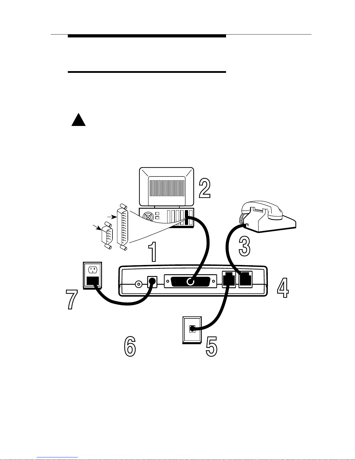
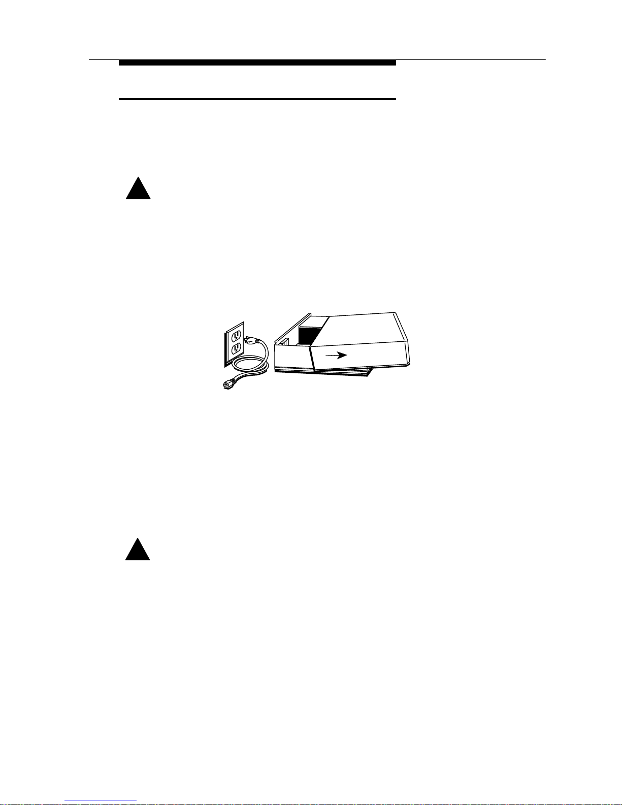
Turn OFF the computer and disconnect the power cord. Be
sure the modem is in a space large enough for good ventilation.
Install using the figure below.
!
CAUTION:
Use only the power supply that came with your modem.
Your modem needs a serial cable to connect it to your
computer. One end must
have a 25-pin plug,
and the other end must
have a socket that
matches the
modem port on
your computer.
This is a 25-pin
or a 9-pin
connector.
Plug the serial
cable into
your modem.
Plug the serial
cable into the
serial port
of your PC.
Plug your phone
into the modem
jack marked
PHONE.
Plug one end of the line
cord (included with your
modem) it into the
modem jack marked
LINE.
Plug the other end of the line
cord into your telephone wall
outlet.
Plug the
small power
connector
into the
modem
jack marked
POWER.
Plug the
transformer
at the other end
of the power cord
into a 110 Vac
power outlet.
Turn on your
modem and
your PC.
495-14657
Go to Chapter 4,
Testing Your Modem,
to verify your installation.
Page 16

3-1
Issue 2 July 1995
3
This chapter describes how to install an internal DataPort PCX
modem (Model 3706).
Internal DataPort PCX
Modem Package
Your package contains the following:
G
One internal DataPort PCX modem.
G
One RJ11 modular 6-foot telephone cord.
G
QuickLink II Fax software diskette and user’s guide.
G
This User’s Guide and Warranty Card. A technical
information update sheet may also be included.
Required Equipment
The internal version of the DataPort PCX modem can be
installed only in an IBM-compatible personal computer. For
proper operation, you must provide the following:
G
An available 8-bit or 16-bit expansion slot within the PC.
G
An available COM port (modem supports COM ports 1–4
and IRQs 2–5).
G
An RJ11 telephone outlet.
G
A telephone with an RJ11 modular telephone cord (if you
wish to use the same outlet for both modem and voice
calls).
G
An IBM-compatible PC. It should have 386 20 MHz or
faster processor for best results.
Page 17

Internal Modem Installation
3-2 Issue 2 July 1995
Internal DataPort PCX
Modem Installation
Use the following procedure to install your modem into an
IBM-compatible PC. Review the entire procedure before
beginning to install your modem, and do not remove the modem
from its protective anti-ESD (electrostatic discharge) bag until
you are ready to place it into your PC.
COM Port and IRQ Configuration
COM port configuration is often the cause of much confusion
when installing internal modems. Before attempting to install
your internal DataPort PCX modem, verify which COM ports are
available on your PC by running the COMTEST program
provided on the QuickLink II Fax diskette.
Select the diskette labeled QuickLink II Fax and insert it into
your floppy drive.
You can run the COMTEST program from DOS or Windows. To
run from DOS, type at the command prompt. To run from
Windows, select Run from the Program Manager File menu and
type in the Command Line window.
TYPE:
a:\comtest (or b:\comtest if you
are using your b: drive)
PRESS:
Enter (or Return)
The COMTEST program recommends COM port and IRQ
settings appropriate for your PC.
The DataPort PCX modem is shipped from the factory
configured for COM port 1 (COM1) and interrupt 4 (IRQ4). If
those settings are already in use in your computer, the
COMTEST program recommends different settings. Make a note
of the recommended settings so you can change the modem
switches before you install the modem.
Page 18
Internal Modem Installation
3-3
Issue 2 July 1995
Installation Procedure
1. Turn Off your PC, and unplug it.
Also turn off all attached devices, such as monitors and
printers.
!
WARNING:
Failure to turn Off the computer while installing or removing
the modem could harm you and/or damage the equipment.
2. Remove the PC’s cover according to the manufacturer’s
directions.
495-1466
0
3. Select an available expansion slot.
If there is already a modem in your PC, remove it and use
the same slot. To use a new slot, remove the screw that
holds the slot cover (metal bracket) in place. Remove the
slot cover but retain the screw.
4. Ground yourself by touching the PC’s chassis before
removing the modem from its shipping bag.
!
CAUTION:
The DataPort PCX modem is shipped from the factory in an
anti-ESD (electrostatic discharge) bag. This is to protect the
modem from any static electricity which is very harmful to
electronic equipment. Do not remove the modem from the
anti-ESD bag until you are ready to install it. Next, ground
yourself by touching the PC’s chassis before removing the
modem from its protective anti-ESD bag.
Page 19
Internal Modem Installation
3-4 Issue 2 July 1995
5. Remove the modem from its shipping bag.
!
CAUTION:
Do not touch the contacts along the bottom edge or any
components on the modem. Handle the modem only by its
outer edges.
Keep the ESD bag in case the modem must be removed or
returned for service.
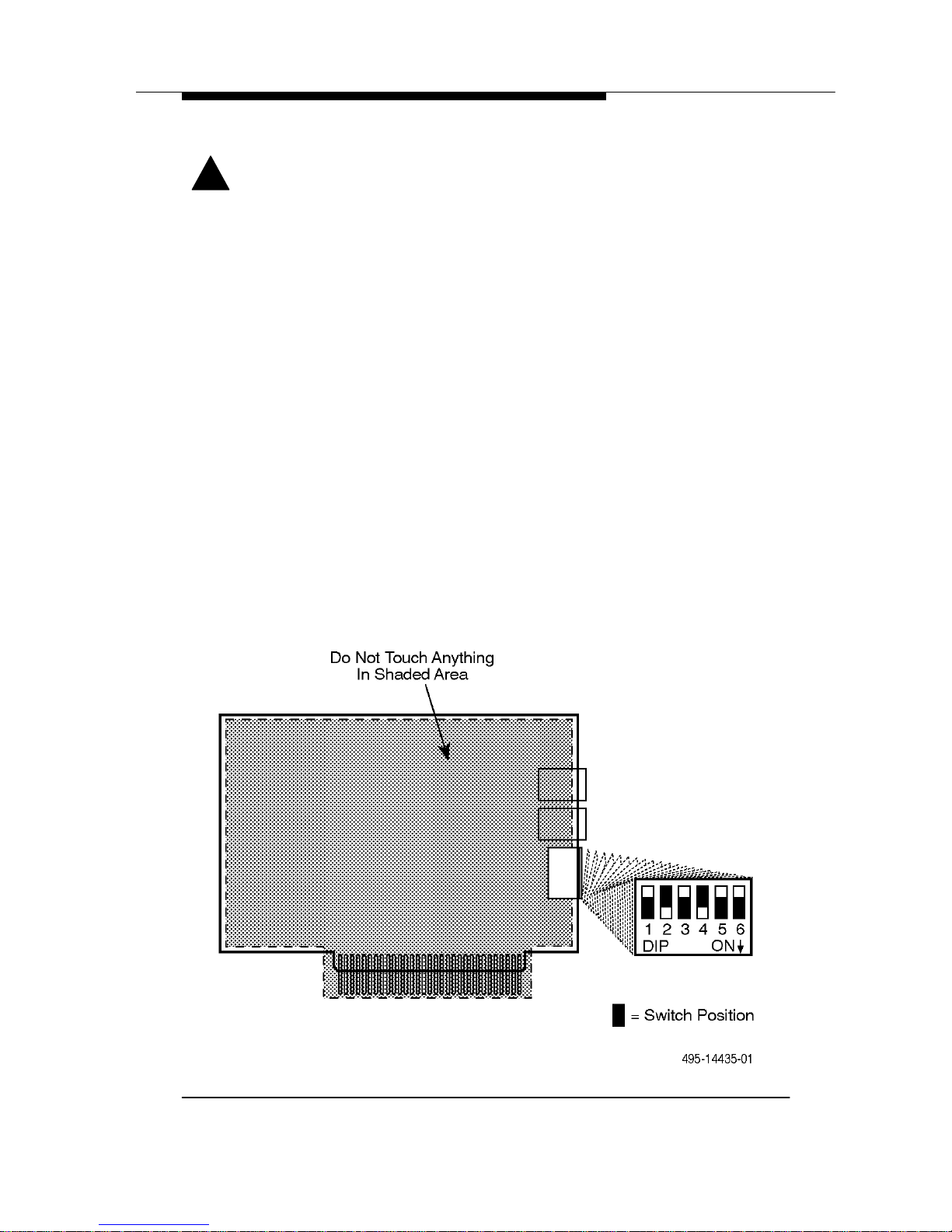
6. Verify that the modem’s switch settings are configured
for the correct COM port. See Figure 3-1 and Table 3-1.
Configure the switches for the COM port/IRQ settings
recommended by the COMTEST program you ran before
installation. If you change the switches, remember the new
settings for when you install your communications software.
Use a small pointed object, such as a pen tip, to change
switches. Table 3-1 lists switch settings for each COM port.
Refer to the documentation for your PC to verify if any
jumpers or switches within the PC should be changed.
Figure 3-1. COM Port Switch Location
Page 20

Internal Modem Installation
3-5
Issue 2 July 1995
Table 3-1. COM Port and Interrupt Settings
COMPort/IRQ
Address Pos 1 Pos 2 Pos 3 Pos 4 Pos 5 Pos 6
COM1/IRQ4 3F8-3FF ON ON Off Off ON Off
COM2/IRQ3 2F8-2FF Off ON Off ON Off Off
COM3/IRQ4 3E8-3EF ON Off Off Off ON Off
COM4/IRQ3 2E8-2EF Off Off Off ON Off Off
COM3/IRQ2 3E8-3EF ON Off ON Off Off Off
COM4/IRQ2 2E8-2EF Off Off ON Off Off Off
COM3/IRQ5 3E8-3EF ON Off Off Off Off ON
COM4/IRQ5 2E8-2EF Off Off Off Off Off ON
Bold indicates factory setting.
7. Carefully insert the modem card into the expansion slot
and fasten the metal bracket.
Hold the modem so that the bracket with the phone jacks
faces the rear of the PC. Press down until the contacts along
the bottom edge of the modem are seated firmly in the
expansion slot connector. Fasten the bracket with the screw
that was removed in Step 3.
8. Replace the cover on the PC.
9. Connect the line cord. See Figure 3-2. Plug one end of the
modular telephone cord into the connector labeled LINE.
10. Connect a telephone. Plug the line cord of your telephone
into the modular connector labeled PHONE. A telephone is
not required for modem operation.
11. Plug in and turn on your PC and continue with
Chapter 4,
Testing Your Modem
, to verify your
installation.
!
WARNING:
In the future, any time you remove the cover of your PC, first
ensure that the telephone line cord has been detached from
the modem.
Page 21

Internal Modem Installation
3-6 Issue 2 July 1995
Figure 3-2. Internal Modem Connections
Page 22

4-1
Issue 2 July 1995
4
Software Installation Overview
RPI is the protocol used between your modem and your PC. The
Windowst version of the QuickLink II Fax diskette installs a
Windows RPI driver (WinRPI) that allows you to use any
Windows fax or communications application. See Appendix D for
a list of DOS applications that support RPI.
Some communications applications may include an error
correction protocol driver called DAPI, which will conflict with
WinRPI. For the DataPort PCX modem to work properly, disable
DAPI when WinRPI is enabled. See the communication
application users manual for instructions.
QuickLink II Fax provides basic features and functionality for
both data and fax communications. It also provides error
correction and data compression services for the modem.
QuickLink II Fax is thoroughly tested by AT&T Paradyne to
ensure compatibility with your DataPort PCX modem.
Before installing the software, make sure the modem is
connected to your computer and turned ON.
If you are installing the Windows version, insert the diskette into
your disk drive, select Run from the Windows File menu, and
enter a:\install or b:\install. Respond as prompted by the
program. To ensure WinRPI compatibility with any Windows
communications application, check the Compression and Error
Correction Software Drivers box on the installation screen.
Allow
the installation program to restart Windows.
See
About WinRPI
at the end of this chapter.
If you do not choose to install QuickLink II Fax, uncheck the
QuickLink II Fax for Windows box to install only the WinRPI.
Page 23

Testing Your Modem
4-2 Issue 2 July 1995
If you are installing the DOS version, insert the diskette into your
disk drive, change to either drive a: or drive b:, and type dosinst
at the DOS prompt. Respond as prompted by the program.
See Appendix C for information about the initialization command
string for QuickLink II Fax.
Testing Your Connections
The purpose of this section is to verify both the modem-tocomputer connection and the modem-to-dial-line connection.
Modem Connection Test
1. Turn your computer ON.
(The internal DataPort PCX modem derives power from the
PC; therefore, it automatically powers ON.)
2. If you are using the QuickLink II Fax software supplied
with your modem, install and start the software. If you
have already installed the software you intend to use, go
to Step 3.
Follow the installation and start-up procedures described in
the QuickLink II Fax support documentation. An overview of
the installation appears at the beginning of this chapter.
3. Start your communications program.
Refer to your software’s documentation for start-up
procedures.
If you decide not to use the provided software, then select
the DataPort PCX modem driver that appears in your
software. If a DataPort PCX driver is not listed, try the
suggestions in Appendix C. You must have installed the
Compression and Error Correction Software Drivers
discussed earlier in this chapter.
If you are unable to set up your software for the DataPort
PCX, load the QuickLink II Fax software on your computer
and use it to dial into the AT&T Paradyne BBS. Information
specific to your software may be available on the BBS.
Page 24

Testing Your Modem
4-3
Issue 2 July 1995
4. Test the modem connection by typing AT and then
pressing Enter.
The modem should respond with an OK. This indicates that
your modem and computer are communicating correctly.
Now test the connection between your modem and the
telephone line by following the procedures in the
Dial-Line
Connection Test
section.
If an OK does not appear, verify that the modem and
communications software are configured for the same COM
port, and repeat this step. (For the external modem, the TR
LED should be ON.)
If the modem still does not respond, refer to Chapter 6,
Troubleshooting
, for additional tips.
Dial-Line Connection Test
The following procedures test the connection of your modem to
the dial telephone line. Step 1 verifies the dial-line connection,
and Step 2 allows you to dial the AT&T BBS and log on as a new
user.
If you are using Pulse (rotary) dialing, type ATDP instead of the
ATDT shown in this chapter. If you need to dial some other
number in addition to or instead of 1 before the area code, or
you are calling from the 813 area code, change your dial strings
appropriately. Your modem must dial the same way you would
dial using your telephone, with the same prefixes and pauses for
dial tone. See the Dial command in Appendix B for information
about special dialing modifiers you can insert in a dial string.
1. Enter the following dial string:
TYPE:
ATDT 1813-532-5254;h
PRESS:
Enter
The dial string consists of the dial command (ATD), the Tone
dial modifier (T), the telephone number (spaces and dashes
are not required, and are only used to enhance readability),
semicolon (;) modifier which allows additional commands to
be added to a single line, and the hang up (h) command
which disconnects the call.
Page 25

Testing Your Modem
4-4 Issue 2 July 1995
If the modem is correctly connected, you will hear a dial tone
as the modem goes off-hook, and then the tones of the
modem dialing the telephone number. (On the external
modem, the OH (off-hook) light turns ON.)
The modem then hangs up and displays an OK. (The OH
light turns Off.)
This brief test indicates that your modem is correctly
connected to the telephone line. If you would like to register
on the AT&T Paradyne BBS, proceed to Step 2.
If you do not hear a dial tone, make sure the telephone cord
is connected to both the modem and the telephone wall
outlet. Otherwise, refer to Chapter 6,
Troubleshooting
.
2. Dial the AT&T Paradyne BBS and log on as a new user.
TYPE:
ATDT1813-532-5254
PRESS:
Enter
At this point, you hear the modem go off-hook, dial the
telephone number, and connect with another modem.
Next, a series of high-pitched tones can be heard as the two
modems determine how to transfer data, at what speed, and
whether to use error control.
When this handshaking process is complete, a CONNECT
message appears on your screen.
3. Enter your name and any other requested information
as you are prompted for it.
You are now logged on to the AT&T Paradyne BBS. If you
wish, you can scan the BBS for documentation updates and
general information about your DataPort PCX modem and
other dial modem products offered by AT&T.
Page 26

Testing Your Modem
4-5
Issue 2 July 1995
About WinRPI
WinRPI provides data compression and error correction for
Windows communications and fax applications. Install WinRPI
by checking the Compression and Error Correction Software
Drivers box on the QuickLink II Fax installation screen, whether
or not you want to install the QuickLink II Fax application. The
setup program creates a WinRPI group containing a WinRPI
Enhancer icon on your desktop. Close the WinRPI group to
minimize its size.
Software Setup
This section shows how to set up your DataPort PCS modem for
some popular online services and communications programs.
Make sure that the COM port setting for your software
(sometimes called Connector or Port) is set to the COM port you
are using for your DataPort PCX modem.
Table 4-1
shows which modem type you should select from the
list your software provides, and a typical initialization command
string. (Spaces are shown for clarity and are optional.)
Table 4-1. Software Initialization Strings
Service or
Program
Modem Type Initialization String
America Online
t
Generic
(Hayes Compatible)
AT &F &C1 &D2 &K3 W2
+H11 ^M
CompuServet–
WinCIM 1.4
Hayes
r
AT &C1 &D2 &K3 W2
S0=0 S7=90 S95=44
+H11^M
Reuters
SM
Hayes or
Hayes Compatible
AT &C1 &D2 &K3 +H11
PROCOMM
r
PLUS for Windows
AT&T DataPort 14.4/FAX
(Class 1)
AT &F &C1 &D2 W2
S7=90 +H11 ^M
QuickLink II Fax
t
Class 1 Fax/Modem AT &F &C1 &D2 W2
S7=90 +H11 ^M
WinFax PROt 4.0
AT&T Paradyne Corp.
DataPort 14.4
AT &F &C1 &D2 K3
+H11 \
Page 27
5-1
Issue 2 July 1995
5
You can change the way your modem works by using AT
commands. However, your modem’s factory default
configuration works for most applications; also software in your
PC may automatically reconfigure your modem as required. You
should find that you rarely need to enter AT commands yourself.
If you do, however, please read
AT Command Guidelines
first.
AT Command Guidelines
The following are guidelines for using AT commands.
G
Most AT commands are entered using the format AT
Xn
where X is the AT command and n is the specific value
for that command. Some of the modem’s internal
settings, called S-registers, are changed directly using a
command of the format ATS
r=n
, where r is the
S-register number and
n
is the value it is to be set to.
G
AT commands must be entered while the DataPort PCX
modem is in Command mode. When the DataPort PCX
modem is in online Command mode (when the modem
is online with another modem) and RPI is enabled, the
only valid AT command is ATH. Command mode is an
idle state in which the modem interprets entries from the
computer as commands, not data.
G
The escape sequence (which consists of three
consecutive plus characters — +++) is used to enter
online Command mode from Data mode. Data mode is a
state where all entries made from the computer are
considered data and are transmitted and received
between modems. To return to Data mode from online
Page 28

Using AT Commands
5-2 Issue 2 July 1995
Command mode, use the ATO command. The command
is valid only when RPI is disabled.
G
All commands (except the A/ repeat command and the
+++ escape sequence) must begin with the characters
AT (attention) and end by pressing the Enter key.
G
The AT (or at) prefix can be upper- or lowercase, but the
modem will not recognize mixed case prefixes (At or aT).
G
The data character format (how your data is structured)
for the AT command set must match the format used by
the other modem in a link, and must be one of the
following. It can be set using your communications
software:
— 8 data bits + no parity + 1 stop bit.
— 7 data bits + parity + 1 stop bit (parity can be
odd, even, mark, or space).
G
Commands can be entered one at a time or in strings
(several commands at once). Spaces, parentheses, and
hyphens are ignored.
G
Commands described in this manual with the suffix
n
have several options associated with them. For example,
in the L
n
command, L0 sets the speaker volume to Low
and L3 sets the speaker volume to High. When no value
is specified for such commands, the command is treated
as if a zero were entered. For example, the command
string ATL has the same effect as ATL0.
G
Valid commands are acknowledged with numeric or word
result codes (unless the result codes have been
disabled using the Q1 command). Appendix E lists all
available result codes with numeric and word
equivalents.
Entering AT Commands Using
QuickLink II Fax
To enter AT commands using QuickLink II Fax, type them in the
Terminal Window (the area under the menu and button bar),
then press the Enter or Return key on your computer keyboard.
Responses from the modem are returned to the Terminal
Window. For example, to view the configuration option settings
in your DataPort PCX modem, type at&v and press Enter.
The modem responds with a display of active modem settings.
Page 29

6-1
Issue 2 July 1995
Troubleshooting
6
Most modem problems are a result of incorrect cabling or
incorrect settings within your communications or fax software.
This chapter provides a list of common problems (P:) that you
may encounter after installation, followed by likely solutions (S:).
Configuration Problems
P: Your modem stops responding after it receives a
command string from you or your communications
program.
S: Reset the modem’s default configuration with the AT&F
command.
P: You do not know what initialization string is required
for an application.
S: If the default configuration does not work satisfactorily,
follow the guidelines in Appendix C.
Power Problems
P: Your modem does not power ON, or does not respond.
S: Ensure that all related software is directed to the correct
COM/IRQ combination. Check your COM port using the
Control Panel Ports icon under Microsoft Windows, or the
“Test an installed modem” feature of the COMTEST
program. Set QuickLink II Fax to communicate with this port
using the Modem Setup window.
Page 30

Troubleshooting
6-2 Issue 2 July 1995
S: For an external modem, make sure the AC power
transformer is plugged into an AC power source, its
low-voltage lead is plugged into the modem, and the
modem is turned ON.
S: For an external modem, use only the power supply that
came with your modem.
S: For an internal modem, remove the telephone cord from the
modem, turn the PC Off and unplug it, open the PC, and
make sure that the modem is properly seated in the
expansion slot.
S: If your modem replaced an internal modem, remove or
disable the old modem. Refer to your PC documentation.
Command Echo Problems
P: You enter commands from the keyboard, but nothing
appears on your monitor. (You type AT and nothing
happens.)
S: Make sure your communications program is set for the
COM port that your modem is connected to (external
modem) or configured for (internal modem).
For the external modem, this can be done by holding down
a keyboard character and watching the modem’s SD light to
see if it flashes. If it flashes as keys are pressed, the
modem is receiving the data from the PC. Turn character
echo ON as described in the next solution.
S: Issue the ATE1 command (character echo ON) to make
sure that characters can be echoed back to your monitor.
An OK response should appear. Type AT and press Enter to
make sure characters are displayed on your monitor.
S: For an external modem, make sure that the cable between
the modem and the PC is a standard RS-232 cable that
supports flow control and modem control signals. If the
cable is not the correct type or has been cut or crushed,
replace it. (Null modem cables, also known as crossover
cables, cannot be used.)
S: For an external modem, if your computer has more than
one serial port, try connecting the cable to another port.
Page 31

Troubleshooting
6-3
Issue 2 July 1995
S: Make sure that your communications software has a valid
character format. Valid formats consists of 8 data bits with
no parity, or 7 data bits with even, odd, mark or space
parity.
S: Make sure that your software is set to a valid DTE rate. The
DataPort PCX supports DTE data rates from 57,600 bps to
300 bps. Your software may refer to this as the Baud Rate.
S: Make sure that your communications software is offline and
in Terminal mode.
Dial Problems
P: The message NO DIALTONE appears after dialing a
telephone number.
S: Make sure that the telephone cord is connected to the
modem and wall outlet. Dial the telephone number again.
S: Attach a telephone directly to the wall outlet and verify that
a dial tone exists. If one does not, contact your local
telephone company.
S: Use the ATM1 or ATM2 command to turn the speaker ON
and listen for a dial tone when you issue an ATD
n
(Dial)
command. If no dial tone is heard, you may have a bad
telephone cord.
S: Disable the Dial Tone Detect command (X0, X1, and X3)
before dialing. This forces the modem to dial without
detecting a
dial tone on the telephone line. This type of
dialing is known as Blind Dialing.
P: The message NO CARRIER appears after dialing a
telephone number.
S: Make sure you dialed a correct and valid telephone number,
and that a modem is connected to the other side.
S: Try dialing a number known to be valid, such as the AT&T
Paradyne BBS.
S: Make sure that no additional characters are sent to the
modem during the connection process. The modem
automatically aborts the call if it receives any.
Page 32

Troubleshooting
6-4 Issue 2 July 1995
Answer Problems
P: Your modem does not answer.
S: Make sure the telephone cord is connected to the modem’s
LINE connector .
S: Attach a telephone to the wall telephone outlet and verify
that it rings during incoming calls.
S: Make sure that the Auto-Answer Ring Number configuration
option (S0) is set to a value other than 0 (disable). Use the
ATS0? command to view the setting of S0.
S: Make sure that the computer is providing DTR to the
modem (on the external modem, the TR LED should be lit).
If the computer does not provide DTR to the modem, verify
that the modem’s &D command (DTR Action) is set for
Ignore (&D0).
P: Your modem answers when you do not want it to.
S: Ensure that your communication software is not running.
S: Ensure that S-register S0 is set to 0.
S: If you have an external modem, turn it off.
Connect Problems
P: Your modem dials, but does not connect.
S: If the modem is operating behind a PBX, determine whether
a 9 and W (Wait for dialtone) must precede the telephone
number.
S: Determine whether you should use Tone (ATDT) or Pulse
(ATDP) dialing.
S: During the dialing or handshaking process, if any key on the
keyboard is pressed, the call will disconnect. This is known
as any-key abort and is standard operation for dial
modems. Try dialing again, and wait for the CONNECT or
BUSY message to display before entering data from the
keyboard.
Page 33

Troubleshooting
6-5
Issue 2 July 1995
P: Your modem answers, but does not connect.
S: Make sure that the modem is configured for Automode
(ATF0). This allows the modem to connect to any modem
that recognizes CCITT V.32bis, V.32, V.23, V.22bis, V.22,
V.21, and Bell 212A and 103J modulation schemes. The
DataPort PCX modem does not support other vendors’
proprietary modulation schemes.
S: Determine the originating modem’s modulation scheme,
and then use ATFn (select modulation) to force your
modem to operate at the same modulation scheme as the
originating modem.
S: To test your modem’s hardware, perform a Local Analog
Loopback test (AT&T1) and verify that data entered at the
computer is echoed back to the computer. Before starting
the test, disable Error Control mode using either the AT\N0
or AT\N1 command. Issue the AT&T1 command, and begin
to enter data from your keyboard. It should
appear on your
monitor. To stop the test, escape to command mode (+++)
and issue the AT&T0 command.
Disconnect Problems
P: Your modem dials and connects with another modem,
but after a moment, disconnects the call.
S: Your modem might be trying to communicate with an older
modem that does not support error control. (This is known
as an error control disconnect, where the modem is
configured to establish a call using error correction. If the
modems cannot negotiate error control, then a disconnect
occurs.)
Disable error control in your modem by entering an AT\N0
command. This places your modem into Buffer mode, a
non-error control mode. Try dialing the number again.
To restore error control to your modem, turn your modem
off and on.
S: You may have a poor telephone line connection. Try dialing
again.
Page 34

Troubleshooting
6-6 Issue 2 July 1995
S: Your telephone may have Call Waiting enabled. Refer to
your local telephone book for procedures to disable this
feature. You may add the disable code to your dial strings.
S: To test your modem hardware, perform a Local Analog
Loopback test (AT&T1) and verify that data entered at the
computer is echoed back to the computer. Before starting
the test, disable Error Control mode
using either the AT\N0
or AT\N1 command. Issue the AT&T1 command, and begin
to enter data from your keyboard. It should appear on your
monitor. To stop the test, escape to Command mode (+++)
and issue the AT&T0 command.
P: Your modem does not disconnect the call and hang up.
S: Change the setting of the &D command from Ignore (&D0)
to Standard RS-232 operation (&D2).
File Transfer Problems
P: You are transmitting a compressed file, but the
throughput seems to be slow.
S: MNP5 data compression can add more overhead to a
compressed file. Disable data compression using the
QuickLink II Fax Connection Setup window, and resend the
file.
P: You experience several errors while transferring a file.
S: Verify that your modem and communications software are
configured for the same type of flow control, for example,
either RTS/CTS (AT&K3) or XON/XOFF (AT&K4).
If you are using XON/XOFF flow control, make sure the
modem’s parity matches the computer’s parity. Verify this
within the communications software.
Make sure that your modem’s parity matches the parity of
the remote end. A mismatch in parity will cause eccentric
errors, such as a single line constantly being repeated.
Page 35

Troubleshooting
6-7
Issue 2 July 1995
S: Set the software’s DTE rate (the speed of the modem-
to-computer connection) to a lower speed. (Your software
may refer to this as the Baud Rate.) The internal DataPort
PCX modems use a 16550A-compatible UART; however,
the external DataPort PCX modems depend on the
computer’s COM port UART. If you know your PC has a
slower UART such as an 8250, or you do not know what
kind of UART it has, do not exceed a DTE rate of
19,200 bps. If a successful transfer occurs at low speeds,
then you may want to upgrade your computer’s COM port
UART.
S: Use a different file transfer protocol. Some protocols, such
as Ymodem-G, are very sensitive and may cancel your file
transfer. Try the Zmodem protocol.
S: The Xmodem protocol may conflict with error control (such
as V.42). Issue the AT\N0 command to turn off error control
when you are using Xmodem.
S: For Windows systems, ensure that the flow control setting
of the port under the Control Panel is the same as that
specified in your communications program.
Character Format Problems
P: You make a successful connection, but nonsensical
strings of characters appear on your screen.
S: The other modem may be configured for a different
character set. Check the number of data bits, type of parity,
and number of stop bits required by the remote system you
are trying to communicate with.
Refer to your software documentation for instructions on
changing your character set. In QuickLink II Fax, use the
Line Settings window .
S: If there is an Autobaud setting in your software, disable it.
S: Configure the modem for no error control (AT\N0).
Page 36

Troubleshooting
6-8 Issue 2 July 1995
P: You are unable to log on to an online service.
S: Verify the character structure of the online service and
make appropriate changes in your software before dialing.
Some services, such as CompuServet and GEnie
SM
,
require a character format of 7E1 (7 data bits, even parity,
and 1 stop bit).
S: Configure the modem for 2400 bps (ATF5) with no error
control (AT\N0) and try to call again.
Rate and Protocol Problems
P: Your modem is configured to operate at its maximum
speed, but connects at a lower speed, such as
2400 bps.
S: With Automode enabled (ATF0), your modem will match its
dial-line rate and modulation scheme with the other
modem’s dial-line rate. Therefore, if the other modem is
configured to operate at 2400 bps (V.22bis), the DataPort
PCX modem will connect at that rate. Ask the remote
modem’s owner to determine the highest rate the remote
modem can support.
S: The DataPort PCX modem does not support other vendors’
proprietary systems and may be forced by the other modem
to connect at a lower rate.
P: Your modem is configured for V.17 fax (14,400 bps), but
faxes at a lower speed.
S: The other fax modem/fax machine may not support
V.17 fax.
S: Make sure that your fax software supports V.17 fax.
S: Make sure that 14,400 bps is selected as the send and
receive rate in your fax software.
P: Your modem never connects using V.42bis
compression.
S: Ensure that the software you are using supports RPI.
S: Ensure that V.42bis support is enabled in the software. In
QuickLink II Fax, use the Connection Setup window.
Page 37

Troubleshooting
6-9
Issue 2 July 1995
S: Ensure that RPI is enabled both in the software and in the
modem (AT+Hn command). QuickLink II Fax automatically
supports RPI.
Fax Problems
P: Modem cannot send or receive a fax.
S: Make sure that your fax software is correctly installed.
S: Check your fax software to see if there is an Answer mode
or Receive Fax setting that must be enabled.
S: Make sure your fax software is set up for Class 1 fax.
P: Sections of your fax are missing.
S: This often indicates a noisy telephone line or a flow control
problem. To resolve the flow control problem, try using
hardware flow control
(RTS/CTS). This must be enabled in
your software (refer to the software’s documentation) and
set within your modem using the AT&K3 command
(RTS/CTS flow control).
P: Your fax did not complete, and your modem displays
result codes in the numeric format.
S: For some reason your modem and software are no longer
communicating, and, as a result, your modem is stuck in fax
mode. Type ATE1V1 and press Enter . The software should
respond with an OK. Try sending or receiving the fax again.
Page 38

A-1
Issue 2 July 1995
A
Table A-1 describes each front panel LED on DataPort PCX
external modems.
Table A-1. LED Descriptions (1 of 2)
LED
Label
Description
TST Test Mode. When ON, the modem is executing a test.
CD Carrier Detect. When ON, the modem has established a
connection with a modem at the other end of the telephone
line. This LED follows the status of the CD signal, Pin 8 of the
EIA RS-232 interface. (This description assumes that the
&C command is configured for standard EIA RS-232
operation (&C1). Refer to the &C command in Appendix B for
more information.)
OH Off-Hook. When ON, the modem is connected to the
telephone line and a data or fax call is in progress.
RD Receive Data. When ON, the modem is sending data to your
computer. This LED follows the status of the RXD signal,
Pin 3 of the EIA RS-232 interface.
SD Send Data. When ON the computer is sending data to the
modem. This LED follows the status of the TXD signal, Pin 2
of the EIA RS-232 interface.
Page 39

Front Panel Status Lights
A-2 Issue 2 July 1995
Table A-1. LED Descriptions (2 of 2)
LED
Label
Description
TR Terminal Ready. When ON, the computer is attached and
ready to send data to or receive data from the modem. Note
that if the &D command is set for Ignore (&D0), then this LED
is always ON.
If the correct COM port is not selected, this LED will not light.
The &D command (DTR Action) must be set for standard EIA
RS-232 operation (&D2) for the LED to function this way.
When Off, data cannot flow between the two devices.
This LED follows the status of the DTR signal, Pin 20 of the
EIA RS-232 interface.
MR Modem Ready. When ON, the modem is ready to send data
to or receive data from the computer. This LED follows the
status of the DSR signal, Pin 6 of the EIA RS-232 interface.
Page 40

B-1
Issue 2 July 1995
B
Table B-1 lists AT commands and S-registers supported by the
DataPort PCX modem. This table lists standard AT commands
and S-registers first (e.g., ATA and ATS0=0), followed by
extended AT commands: the ampersand (&) commands
(AT&C
n
); the backslash (\) commands (AT\Kn); the percent (%)
commands (AT%E
n
), and the plus(+)commands(AT+FCLASS).
Boldface type indicates factory default settings (see the &F
command).
See
AT Command Guidelines
in Chapter 5 for an explanation of
command entry and usage.
Table B-1. AT Command and S-Register List (1 of 21)
AT Command/
S-Register
Description
+++ ESCAPE SEQUENCE
Causes the DataPort PCX modem to exit Data mode
and enter online Command mode. The O command
returns you to Data mode.
The escape sequence must be preceded and
followed by a pause to distinguish it from data. (See
S12.) The value of the escape character can be
changed. (See S2.)
A/ REPEAT LAST COMMAND
Repeats the previous command string entered. Do
not precede the A/ command with AT or follow it with
a carriage return.
Page 41

AT Commands and S-Registers
B-2 Issue 2 July 1995
Table B-1. AT Command and S-Register List (2 of 21)
AT Command/
S-Register
Description
A ANSWER MODE
The Answer command causes the DataPort PCX
modem to go off-hook and answer an incoming call.
The Answer command also puts the modem in data
(Answer) mode in talk/data operation. (See D
n
.)
B
n
CCITT/BELL MODE
Determines the protocol used if the dial-line rate is set
to 300 or 1200 bps. It has no effect if the rate is set to
another value. (See F
n
.)
B, B0 V.21 or V.22 (300 or 1200 bps)
B1 Bell 103 or Bell 212A (300 or 1200 bps)
D
n
DIAL
Any digit or symbol (0–9, *, #, A, B, C, D) may be
dialed as a touch-tone, but only 0–9 can be dialed in
Pulse Dial mode. Spaces, hyphens, and parentheses
are ignored.
DIAL COMMAND MODIFIERS
The following modifiers can be used in a dial string:
T Touch-tone dialing. Any digit 0–9, * , # , A,
B, C, or D is valid.
P Pulse dialing. Only the digits 0–9 are valid;
other characters are ignored.
W Wait for dial tone. The modem waits for a
second dial tone before processing the dial
string. This can be the initial dial tone or
can be used when dialing through a tandem
PBX. For example: ATDT9W555-6789
, Pause. The modem pauses before
processing the next character in the dial
string. Pause length is determined by the
value of S8 (Pause Time).
! Hook flash. The modem goes on-hook for
0.5 seconds, then returns off-hook.
Page 42

AT Commands and S-Registers
B-3
Issue 2 July 1995
Table B-1. AT Command and S-Register List (3 of 21)
AT Command/
S-Register
Description
(DIAL COMMAND MODIFIERS, continued)
; Return to Command mode. Allows
AT command strings that exceed the length
limit to be linked together. This is useful
when using a calling card number or an
international telephone number. The
modem remains in Command mode until a
dial string ends without a semicolon.
@ Quiet answer. The modem waits for
5 seconds of silence before continuing with
the next part of the dial string. If silence is
not detected in the amount of time specified
by S-register S7, the modem terminates the
call and sends NO ANSWER or BUSY to
the computer.
& Wait for credit card dialing tone. If the tone
is not detected in the time specified by S7,
the modem aborts the dialing sequence.
returns on-hook, and generates an error
message.
Spaces, hyphens, and parentheses
These may be included for readability, but
do not affect dialing.
No characters
If a Dial command is entered with no
numbers or modifiers, the modem goes
online and proceeds with handshaking in
Originate mode. It identifies itself as a fax
modem or a data modem according to the
setting of +FCLASS.
NOTE: Before the modem goes online, any character
from the DTE aborts the dial sequence.
DL DIAL LAST NUMBER
Redials the last number dialed. Only the last part of
dial strings separated by the Return to Command dial
modifier (:) is redialed.
Page 43

AT Commands and S-Registers
B-4 Issue 2 July 1995
Table B-1. AT Command and S-Register List (4 of 21)
AT Command/
S-Register
Description
DS=
n
DIAL STORED NUMBER
Dials telephone number stored in directory location
n
(where n is a number, 0–3). The DataPort PCX
modem supports four telephone directory entries.
(See &Z.)
E
n
COMMAND CHARACTER ECHO
Controls whether characters entered at your keyboard
are displayed on your monitor when the modem is in
command mode.
E, E0 Disables echo
E1 Enables echo
F
n
SELECT LINE MODULATION
Controls the line modulation and VF rate and modifies
the setting of N
n.
F0 Selects auto-detect mode. All supported
speeds and modulations are available
for selection by the remote modem.
F1 Selects V.21 or Bell 103J (300 bps)
according to the setting of B
n
.
F2 Not supported.
F3 Selects V .23. The originating modem’s rate
is set to 75 bps, and the answering
modem’s rate is set to 1200 bps.
F4 Selects V.22 or Bell 212A (1200 bps)
according to the setting of Bn.
F5 Selects V.22bis (2400 bps).
F6 Selects V.32bis or V.32 at 4800 bps.
F7 Selects V.32bis at 7200 bps.
F8 Selects V.32bis or V.32 at 9600 bps.
F9 Selects V.32bis at 12,000 bps.
F10 Selects V.32bis at 14,400 bps.
Page 44

AT Commands and S-Registers
B-5
Issue 2 July 1995
Table B-1. AT Command and S-Register List (5 of 21)
AT Command/
S-Register
Description
H
n
HOOK CONTROL
Controls the modem’s on-hook or off-hook status.
The ATH or ATH0 command causes the modem to go
on-hook, disconnecting the call. It also forces the
modem into Talk mode; if the telephone receiver is
lifted off-hook before the ATH0 command is entered,
the connection is maintained.
The ATH1 command causes the modem to go
off-hook, causing a “Make Busy” condition. It also
forces the modem into data (Originate) mode. This is
like the ATD command with no number , except that
automatic disconnects do not occur.
H, H0 On-hook
H1 Off-hook
I
n
IDENTIFICATION
Returns information about the modem.
I, I0 Displays product code (14400).
I1 Displays a checksum value.
I2 Displays OK result code.
I3 Displays the firmware revision level, model,
and interface.
I4 Displays a firmware-dependent code.
I5 Displays country code.
I6 Displays data pump model and revision
code.
L
n
SPEAKER VOLUME
Adjusts the volume of the modem’s speaker.
L, L0, L1 Low volume (Default for &F0)
L2 Medium volume (Default for &F1)
L3 High volume
Page 45

AT Commands and S-Registers
B-6 Issue 2 July 1995
Table B-1. AT Command and S-Register List (6 of 21)
AT Command/
S-Register
Description
M
n
SPEAKER ON/OFF CONTROL
Determines the status of the modem’s speaker.
M, M0 Speaker always Off.
M1 Speaker On until carrier signal becomes
active.
M2 Speaker always ON.
M3 Speaker off while dialing, on while
handshaking, until carrier signal becomes
active.
N
n
AUTOMODE ENABLE
Enables or disables Automode detection. The setting
of N is affected by the ATF
n
command: ATF0 is
equivalent to N1; ATF1 through F10 set N to 0.
However, the N1 command does not set an F
n
value.
When F0 (Automode) is active but N0 (Disable
Automode) is issued, subsequent connections are
attempted at the most recently sensed DTE rate.
N0 Disables Automode detection.
N1 Enables Automode detection.
O
n
RETURN ONLINE TO DATA MODE
When the DataPort PCX modem is set to AT+H0 (RPI
disabled), AT0 forces the modem from online
Command mode to Data mode, with or without a
retrain. If result codes are enabled, the O command
also displays the current VF rate. When RPI is
enabled, AT0 is not supported.
O, O0 Returns to online Data mode without a
retrain.
O1 Retrains then returns to online Data mode.
P PULSE DIAL
Specifies rotary-type dialing. See D
n.
Page 46

AT Commands and S-Registers
B-7
Issue 2 July 1995
Table B-1. AT Command and S-Register List (7 of 21)
AT Command/
S-Register
Description
Q
n
RESULT CODES
Allows modem response messages, such as OK
and BUSY, to be displayed. Refer to the V and
X commands for more information. See Table G-1 in
Appendix G for a list of result codes.
Q, Q0 Enables result codes
Q1 Disables result codes
S
n=r
CHANGE S-REGISTER
Assigns a new value to the specified S-register.
n
= S-register
r
= new value of S-register
Sn? VIEW S-REGISTER
Displays the value of a specific S-register
n
(for
example, ATS0?).
S0=
n
AUTO-ANSWER RING NUMBER
Number of rings before the DataPort PCX modem
answers. Accepts a ring count from 0 to 255. Factory
setting is 0. If set to 0, a call must be answered
manually, or by issuing the A command.
0 = Disable
1 to 255 = Number of rings before modem will answer
S2=
n
AT ESCAPE CHARACTER
Sets the AT Escape Character to a value from 0 to
127. A setting greater than 127 disables the escape
sequence.
Factory setting is 43, the ASCII + character.
S3=
n
CARRIAGE RETURN CHARACTER
Sets the Carriage Return Character to a value from
0 to 127.
Factory setting is 13, the ASCII carriage return.
Page 47

AT Commands and S-Registers
B-8 Issue 2 July 1995
Table B-1. AT Command and S-Register List (8 of 21)
AT Command/
S-Register
Description
S4=
n
LINE FEED CHARACTER
Sets the Line Feed Character to a value from
0 to 127.
Factory setting is 10, the ASCII line feed character.
S5=
n
BACKSPACE CHARACTER
Sets the backspace character to a value from 0 to 32.
The modem will not recognize a backspace character
of a higher value.
Factory setting is 08, the ASCII backspace character.
S6=
n
BLIND DIAL PAUSE TIME
Sets the amount of time the DataPort PCX modem
waits before dialing when Dial Tone Detect is disabled
(see X
n
). Accepts a pause time from 0 to
255 seconds, but values of 0 and 1 have the same
effect as a value of 2.
Factory setting is 2 seconds.
S7=
n
NO ANSWER TIMEOUT
Sets the amount of time the DataPort PCX modem
waits before abandoning a call that produces no
answer tone. Accepts a value from 0 to 255 seconds,
but a value of 0 has the same effect as a value of 1.
The timer is reset each time a “W” or “@” is
encountered in the Dial string. (See D
n
.)
Factory setting is 50 seconds.
S8=
n
PAUSE TIME FOR THE “,” DIAL MODIFIER
Sets the length of the pause invoked by a comma in
the Dial command string. (See D
n
.) Accepts a value
from 0 to 255 seconds.
Factory setting is 2 seconds.
S9=
n
CARRIER DETECT RESPONSE TIME
Determines how long the remote modem’s carrier
signal must be present before it is recognized by your
modem. Accepts a value from 1 to 255 in 0.1 second
increments.
Factory setting is 6 (0.6 seconds).
Page 48

AT Commands and S-Registers
B-9
Issue 2 July 1995
Table B-1. AT Command and S-Register List (9 of 21)
AT Command/
S-Register
Description
S10=
n
NO CARRIER DISCONNECT
255 = Disable
Sets the amount of time the DataPort PCX modem
will wait before disconnecting when no carrier signal
is detected. Accepts a value from 0 to 254 in
0.1 second increments. S10 must be set to a value
higher than the value of S9 or the modem will
disconnect before it recognizes the carrier.
Factory setting is 14 (1.4 seconds).
S11=
n
DTMF TONE ON TIMER
Sets the duration of a DTMF tone (touch-tone).
Accepts a value from 50 to 255 milliseconds. A value
less than 50 defaults to 50 milliseconds.
Factory setting is 95 milliseconds.
S12=
n
ESCAPE GUARD TIME
Sets the duration of the pause required before and
after an escape sequence (+++) for it to be treated as
an escape sequence and not data. Accepts a value
from 0 to 255 in 20 millisecond increments.
Factory setting is 50 (1 second).
S18=
n
TEST TIMEOUT
Sets the duration of any test initiated by the
&T command. If S18=0, a test runs indefinitely
unless manually canceled (see &T0). Accepts a value
of 0 for Disable, or from 1 to 255 seconds.
Factory setting is 0 (Disable).
S25=
n
DELAY TO DTR
Sets the length of time that the modem will ignore
DTR before taking the action specified by &D
n
. S25
specifies duration in seconds for synchronous modes
and 10-millisecond increments for other modes.
Accepts a value from 0 to 255.
Factory setting is 5.
Page 49

AT Commands and S-Registers
B-10 Issue 2 July 1995
Table B-1. AT Command and S-Register List (10 of 21)
AT Command/
S-Register
Description
S26=
n
RTS-TO-CTS DELAY
Sets the amount of time the DataPort PCX modem
waits after receiving the RTS signal before sending
the CTS signal to the computer. Accepts a value from
0 to 255 in 10 millisecond increments. S26 has no
effect if the modem is not in synchronous mode, or if
RTS Action (&R) is set to Ignore.
Factory setting is 1 (10 milliseconds).
S36 RESERVED
S37=
n
LINE CONNECTION SPEED
Sets the line connection speed (see F
n
). Invalid
numbers are treated as 0.
0 = Automode (F0)
1–3 = 300 bps (F1)
4 = Reserved
5 = V.22 1200 bps (F4)
6 = V.22bis 2400 bps (F5)
7 = V.23 (F3)
8 = V.32/V.32bis 4800 bps (F6)
9 = V.32/V.32bis 9600 bps (F8)
10 = V.32bis 12kbps (F9)
11 = V.32bis 14.4kbps (F10)
12 = V.32bis 7200 bps (F7)
13–15 = Reserved
S38
S40
S41
S44
S46
RESERVED
Page 50

AT Commands and S-Registers
B-11
Issue 2 July 1995
Table B-1. AT Command and S-Register List (11 of 21)
AT Command/
S-Register
Description
S95 EXTENDED RESULT CODES
Sets an override of the W
n
command option.
NOTE: The following values are bit positions, not
decimal S-register contents. An option is selected if
its associated bit is set to 1.
0 = CONNECT result code shows DCE speed instead
of DTE speed
1 = Reserved
2 = Enable CARRIER x result code (x=rate)
3 = Enable PROTOCOL NONE result code
4–7 = Reserved
T TONE DIAL
Specifies touch-tone dialing. This is the default type.
(See D
n.)
V
n
RESULT CODE FORMAT
Determines the way result codes are sent to the DTE.
V, V0 Result codes displayed as numbers
V1 Result codes displayed as text
W
n
CONNECT MESSAGE CONTROL
Controls the format of the CONNECT result code
displayed upon connection (only).
W0 CONNECT shows DTE rate
W1 CONNECT shows VF rate, protocol, and
DTE rate
W2 CONNECT shows VF rate
Page 51

AT Commands and S-Registers
B-12 Issue 2 July 1995
Table B-1. AT Command and S-Register List (12 of 21)
AT Command/
S-Register
Description
X
n
EXTENDED RESULT CODES, BUSY TONE
DETECT
X
n
controls two different parameters. Extended result
codes are shown in Table E-1 in Appendix E. Busy
Tone Detect determines whether the modem monitors
the line for a busy signal.
X, X0 Disables extended result codes and busy
tone detect.
X1 Enables extended result codes and
disables busy tone detect.
X2 Enables extended result codes and
disables busy tone detect.
X3 Enables extended result codes and busy
tone detect.
X4 Enables all result codes and busy tone
detect.
Y
n
LONG SPACE DISCONNECT
Determines whether the DataPort PCX modem
disconnects if a long space (more than 1.6 seconds)
is detected, and sends a long space (4 seconds)
when it disconnects.
A cleardown is transmitted instead of a long space in
V.32bis or V.32 modes, but a received long space still
causes a disconnect if this option is enabled.
Y, Y0 Disable
Y1 Enable
Page 52

AT Commands and S-Registers
B-13
Issue 2 July 1995
Table B-1. AT Command and S-Register List (13 of 21)
AT Command/
S-Register
Description
Z
n
RESET AND LOAD ACTIVE
Resets the modem and loads user-defined
configuration options.
Z, Z0 Loads the stored profile 0 configuration
options into Active.
Z1 Loads the stored profile 1 configuration
options into Active.
&C
n
LSD (LINE SIGNAL DETECT) CONTROL
Determines the handling of the remote LSD signal.
&C, &C0 Forced On (Default for &F0)
&C1 Follows standard RS-232 operation. LSD
is ON when RXD output is possible.
(Default for &F1)
Page 53

AT Commands and S-Registers
B-14 Issue 2 July 1995
Table B-1. AT Command and S-Register List (14 of 21)
AT Command/
S-Register
Description
&D
n
DTR (DATA TERMINAL READY) ACTION
Determines the handling of the Data Terminal Ready
signal.
&D, &D0 Interprets DTR according to the value of
&Q
n
as follows:
&Q0, &Q6: DTR is ignored (assumed on).
&Q1: When DTR turns Off, the modem
hangs up. Auto-answer is not affected.
&Q2, &Q3: When DTR turns Off, the
modem hangs up. Auto-answer is disabled.
&D1 Interprets DTR according to the value of
&Q
n
as follows:
&Q0, &Q1, &Q6: When DTR turns off, the
modem returns to asynchronous command
state without disconnecting.
&Q2, &Q3: When DTR turns Off, the
modem hangs up. Auto-answer is disabled
&D2 Interprets DTR according to the value of
&Q
n
as follows:
&Q0, &Q1, &Q6: When DTR turns Off,
the modem hangs up. Auto-answer is
disabled.
&D3 Interprets DTR according to the value of
&Q
n
as follows:
&Q0, &Q1, &Q6: When DTR turns off, the
modem performs a soft reset as if the Z
command were received.
&Q2, &Q3: When DTR turns Off, the
modem hangs up. Auto-answer is disabled.
Page 54

AT Commands and S-Registers
B-15
Issue 2 July 1995
Table B-1. AT Command and S-Register List (15 of 21)
AT Command/
S-Register
Description
&F
n
SELECT FACTORY DEFAULT CONFIGURATION
OPTIONS
&F, &F0 Loads Factory 0 configuration options
into Active memory.
&F1 Loads Factory 1 configuration options into
Active memory.
Factory default settings (&F0) are indicated by bold
type in this table. &F1 settings differ only for the L
n
and &Cn options, and are shown in those sections of
this appendix.
&G
n
V.22BIS AND V.22 GUARD TONE
Determines the nature of the V.22bis and V.22 Guard
Tone.
&G, &G0 Disable
&G1 Disable
&G2 1800 Hz guard tone
NOTE: The ability to change this value is mandatory
in some countries; it is not used in North America.
&K
n
FLOW CONTROL
Determines the flow control settings for data passed
between the computer and the DataPort PCX
modem.
&K, &K0 Disables hardware and software flow
control.
&K3 Enables RTS/CTS (hardware) flow
control.
&K4 Enables XON/XOFF (software) flow control.
&K5 Transparent XON/XOFF (software) flow
control. (XON and XOFF characters are
passed from DTE to DTE.)
&K6 Enables both XON/XOFF and RTS/CTS
flow control. (Default for fax modes.)
Page 55

AT Commands and S-Registers
B-16 Issue 2 July 1995
Table B-1. AT Command and S-Register List (16 of 21)
AT Command/
S-Register
Description
&M
n
ASYNC/SYNC MODE AND COMPUTER DIALER
TYPE
Applies to external DataPort PCX modem only.
Determines the DTR operating mode. The modem
treats the &M command as a subset of the
&Q command. &M1, &M2, and &M3 are for serial
interface operation (external modem) only.
&M, &M0 Enables direct asynchronous operation.
&M1 Enables synchronous Connect mode with
asynchronous offline Command mode.
&M2 Enables synchronous Connect mode with
asynchronous offline Command mode, and
enables DTR dialing of directory slot 0.
&M3 Enables synchronous Connect mode, and
allows DTR to act as a talk/data switch. A
call is manually initiated when DTR is
inactive. When DTR becomes active,
handshaking proceeds in originate or
answer mode (depending on the modem
state).
Page 56

AT Commands and S-Registers
B-17
Issue 2 July 1995
Table B-1. AT Command and S-Register List (17 of 21)
AT Command/
S-Register
Description
&Q
n
ASYNC/SYNC MODE AND COMPUTER DIALER
TYPE
Determines the DTR operating mode. &Q is an
extension of the &M command. &Q1, &Q2, and &Q3
are for the serial interfaced (external) modem only.
&Q, &Q0 Enables direct asynchronous operation.
&Q1 Enables synchronous Connect mode with
asynchronous offline Command mode.
&Q2 Enables synchronous Connect mode with
asynchronous offline Command mode, and
enables DTR dialing of directory slot 0.
&Q3 Enables synchronous Connect mode, and
allows DTR to act as a talk/data switch. A
call is manually initiated when DTR is
inactive. When DTR becomes active,
handshaking proceeds in originate or
answer mode (depending on modem state).
&Q5 Enables asynchronous operation in
Error Control mode.
&Q6 Enables asynchronous operation in
normal mode (speed buffering).
&R
n
RTS/CTS ACTION
Determines the handling of the CTS (Clear To Send)
signal relative to the RTS (Request To Send) signal.
&R, &R0 In synchronous mode, CTS tracks the state
of RTS. S26 defines the RTS to CTS delay.
&R1 In synchronous mode, treats CTS as
always ON; RTS transitions are ignored.
&S
n
DSR CONTROL
Determines the handling of the DSR (Data Set
Ready) signal.
&S, &S0 Forced On.
&S1 DSR becomes active after answer tone is
detected, and inactive after the carrier is
lost.
Page 57

AT Commands and S-Registers
B-18 Issue 2 July 1995
Table B-1. AT Command and S-Register List (18 of 21)
AT Command/
S-Register
Description
&T
n
TESTS
RPI must be disabled before test commands can be
used. Set AT+H0 to disable RPI.
Initiates and terminates Loopback and Pattern tests.
Only one test can run at a time. The modem must be
in Buffer or Direct mode (\N
n
).
If the modem is not offline (disconnected) for tests
&T1, and &T8, the tests will take it offline. The modem
must be online (connected) for tests &T3 and &T7.
When tests &T7 and &T8 end, the modem sends the
DTE a message showing the number of 1,024-byte
blocks in error.
&T, &T0 Stops test in progress and displays results.
&T1 Local Analog Loopback test.
&T3 Local Digital Loopback test.
&T4 Accepts request for Remote Digital
Loopback test received over the VF line.
&T5 Denies request for Remote Digital
Loopback test.
&T6 Remote Digital Loopback test.
&T7 Remote Digital Loopback test with Pattern.
&T8 Local Analog Loopback test with Pattern.
S18 determines how long a test runs.
&V
n
VIEW CONFIGURATION OPTIONS
&V, &V0 Displays current configuration options.
&W
n
WRITE (SAVE) CHANGES TO MEMORY
Saves configuration options in one of two user areas.
(See also Z and &Y commands.)
&W, &W0Saves current configuration options to
Stored Profile 0.
&W1 Saves current configuration options to
Stored Profile 1.
Page 58

AT Commands and S-Registers
B-19
Issue 2 July 1995
Table B-1. AT Command and S-Register List (19 of 21)
AT Command/
S-Register
Description
&X
n
TRANSMIT CLOCK SOURCE
Determines the source of timing.
&X, &X0 Internal. The modem generates the
clock signal.
&X1, &X2 Provided for compatibility only.
&Y
n
DESIGNATE DEFAULT STORED PROFILE
Determines which stored profile (0 or 1) is loaded
when the modem is turned on.
&Y, &Y0 Use stored profile 0.
&Y1 Use stored profile 1.
&Z
n=x
STORE TELEPHONE NUMBERS
Stores telephone number
x
into directory n (0, 1, 2, or
3). The phone number can contain up to 35
characters appropriate to the dial type (Touch-tone or
Pulse), and readability characters such as hyphens.
(See the D and DS commands for more information.)
Page 59

AT Commands and S-Registers
B-20 Issue 2 July 1995
Table B-1. AT Command and S-Register List (20 of 21)
AT Command/
S-Register
Description
\K
n
BUFFER CONTROL, SEND BREAK CONTROL,
BREAK FORCES ESCAPE
Controls whether buffered data is discarded upon a
break sequence (Buffer Control), whether a break
sequence is sent before data (Send Break Control),
and whether a break sequence forces the DataPort
PCX modem into Command mode (Break Forces
Escape).
\K, \K0 Discards data, sends break before data,
and enables Break Forces Escape.
\K1 Discards data, sends break before data,
and disables Break Forces Escape.
\K2 Keeps data, sends break before data, and
enables Break Forces Escape.
\K3 Keeps data, sends break before data, and
disables Break Forces Escape.
\K4 Keeps data, sends data before break, and
enables Break Forces Escape.
\K5 Keeps data, sends data before break,
and disables Break Forces Escape.
\N
n
OPERATING MODE
Determines the mode to be negotiated in subsequent
connections.
\N, \N0 Buffer mode
\N1 Direct mode (external modem) or Buffer
mode (internal modem)
%E
n
LINE QUALITY MONITOR
Determines whether and for what purpose the modem
will monitor line quality.
%E, %E0Disable line quality monitor.
%E1 Enable line quality monitor and auto-retrain.
%E2 Enable line quality monitor and fallback
and fall forward rate negotiation.
Page 60

AT Commands and S-Registers
B-21
Issue 2 July 1995
Table B-1. AT Command and S-Register List (21 of 21)
AT Command/
S-Register
Description
%L LINE SIGNAL LEVEL
Returns a value indicating the received line signal in
dBm.
NOTE: This value is not sensed at the telephone line
connector.
%Q LINE SIGNAL QUALITY
Returns a value indicating the line signal quality. This
is the value checked for the %E1 or %E2 options.
+FCLASS? FAX/DATA MODE QUERY
Displays the fax or data mode expressed as a
number 0 (for data mode), or 1 (for Fax Class 1).
+FCLASS=
n
FAX/DATA MODE SET
Determines whether the modem operates in fax or
data mode.
n
can be one of two values:
0 = Data
1 = Fax Class 1 (EIA/TIA 578)
+H
n
RPI TOGGLE
Determines whether Rockwell Protocol Interface
(RPI) processing is used. RPI uses WinRPI, running
on your PC, for error correction and data compression
services. The initialization string must include +H11
for WinRPI to function.
+H, +H0 Disable RPI.
+H11 Enable RPI.
Page 61

C-1
Issue 2 July 1995
C
This appendix lists the recommended settings for several
communications, remote communications, and fax software
packages. Refer to your software’s user’s guide for the
location of these configuration parameters.
Guidelines for All Software
These overall guidelines apply when using the DataPort PCX
with any software:
G
If your software has an Autobaud selection, make sure it
is Off or Disabled.
G
Your DataPort PCX modem and computer (DTE)
communicate via your computer’s serial port at a variety
of DTE data rates (baud rates) ranging from 300 bps to
57,600 bps. Use your software package to select the
highest possible DTE rate that your computer can
support.
G
If you manually change the DTE rate while the DataPort
PCX modem is offline, enter AT and press the Enter key
before receiving a data transfer. This is known as
Autobaud, where the DataPort PCX modem uses the “A”
character to gather information about the baud rate and
character structure, and ensures that the modem is
configured to the new speed.
Page 62

Communications and Fax Software Settings
C-2 Issue 2 July 1995
For an external modem, if your serial port is configured
for 38,400 bps or higher and you notice errors in your
data transmission, try configuring it to 19,200 bps. Before
using higher data rates again, verify that your serial port
has a 16550A compatible UART that can handle
38,400 bps or higher.
For an internal modem in an 8-bit slot, do not attempt
DTE rates higher than 19,200 bps. An internal modem in
a 16-bit slot supports higher rates.
G
Your DataPort PCX modem supports Class 1 fax. If the
DataPort PCX modem is not listed in your fax software
setup, use a generic Class 1 fax driver, if available.
G
If no DataPort PCX modem driver is listed in your
communications software package, select any
Hayes-compatible modem. This selection will not affect
your data rate.
G
Use Hardware flow control (RTS/CTS) if possible. This is
the recommended flow control method, and the DataPort
PCX default.
G
If your software has a Lock Speed selection, make sure
it is ON.
These and other guidelines are summarized in the following
tables. Table C-1 lists settings you might be required to change
or verify in your communications or fax software. Table C-2 lists
settings you might be required to change or verify in your
modem.
Page 63

Communications and Fax Software Settings
C-3
Issue 2 July 1995
Table C-1. Software Configuration Guidelines
Configuration
Option
Setting (If Available) Likely Uses
Autobaud Off or Disable
Baud Rate (DTE Rate) Maximum computer
can handle; if in doubt,
use 19,200 bps
COM/IRQ As identified by
COMTEST
Data Bits/Parity/Stop
Bits
8-N-1, or as
recommended by the
remote system owner
BBSs and online
services, including
AT&T Paradyne BBS
Hardware Flow
Control (RTS/CTS)
ON or Enable
Lock Speed ON or Enable
Modem Type / Driver DataPort PCX
or
generic (Hayescompatible) Class 1
Fax Modem
Software Flow Control
(Xon/Xoff)
Off or Disable
Terminal Emulation VT100
ANSI
Mainframe connections
AT&T Paradyne BBS
Table C-2. Modem Configuration Guidelines
Configuration
Option
Setting
AT
Command
DTR Action RS-232 &D2 (Default)
Hardware Flow Control
(RTS/CTS Flow Control)
RTS (Modem)/
CTS (DTE)
&K3 (Default)
Line Rate (VF Rate) Maximum Possible F0 (Default)
LSD Control RS-232 &C1 (Default)
Result Codes Enable all V1, W0, X4 (Defaults)
RPI Enable +H11
Page 64

Communications and Fax Software Settings
C-4 Issue 2 July 1995
Guidelines for Specific Software
The AT&T Paradyne BBS (813-532-5254) has the latest
updates, special settings, and initialization strings for some
popular communications and fax packages. If you cannot get
your software to work using the guidelines in this appendix,
install QuickLink II Faxt temporarily so that you can use it to
check the BBS for further information.
If your configuration requires settings to your software or your
modem that are not mentioned here or on the BBS, please let us
know by writing to Technical Publications, telephoning Technical
Support, or uploading information to the BBS.
QuickLink II Fax is shipped already configured for DataPort PCX
modems:
G
The init string is AT&FE1V1&C1&D2S0=0S7=90
G
Baud Rate is 19,200 bps
G
Hardware Flow Control is selected
G
Autobaud is Off
Add the +H11 command to the initialization string to enable RPI.
If you add no other commands, your initialization string should
look like this:
AT&FE1V1&C1&D2S0=0S7=90+H11
If you do not intend to receive a fax from another user, then
change Answer Mode to Data Only.
NOTE:
Change the initialization string and Answer Mode using
the Modem Setup window of QuickLink II Fax.
Page 65

D-1
Issue 2 July 1995
D
Table D-1 lists technical specifications for the DataPort PCX
modem. Table D-2 lists software that supports RPI.
Table D-1. DataPort PCX Technical Specifications (1 of 3)
Specifications
Description
APPROVALS –
External Modem
(Model 3705)
(120 Vac, 60 Hz only)
FCC Part 15 Class B
FCC Part 68 Registration Number: See label on
modem
UL Listed to UL 1950 or Equivalent
CSA Certified to CSA C22.2 No. 950
DOC CS-03 Certification Number: See label on
modem
APPROVALS –
Internal Modem
(Model 3706)
FCC Part 15 Class B
FCC Part 68 Registration Number: See label on
modem
UL Listed as an accessory to UL 1950
or equivalent
CSA Certified as add-on to CSA C22.2
No. 950
DOC CS-03 Certification Number: See label on
modem
Page 66

Technical Specifications
D-2 Issue 2 July 1995
Table D-1. DataPort PCX Technical Specifications (2 of 3)
Specifications Description
AC POWER
REQUIREMENTS –
External Modem Only
(Wall-Mount Transformer)
INPUT:
120 Vac " 10%, 60 Hz, 15W
230 Vac " 10%, 50 Hz (not for North
America)
OUTPUT:
9 Vac, 1000 mA, 9VA (Model 3705)
POWER CONSUMPTION
External Modem
Model 3705
Internal Modem
Model 3706
3500 milliwatts (maximum)
2000 miliwatts (maximum)
DIMENSIONS – External
Modem
Weight .84 pounds (.38 kg) not including power
transformer
Length 7.03 inches (17.85 cm)
Width 5.02 inches (12.75 cm)
Height 1.32 inches (3.35 cm)
DIMENSIONS – Internal
Modem
Weight .21 pounds (96 g)
Length 5.1 inches (13.0 cm)
Width 0.8 inches (1.9 cm)
Height (Board only) 2.9 inches (7.3 cm)
ENVIRONMENT
Operating Temperature
Storage Temperature
Shock and Vibration
32°F (0°C) to 122°F (50°C)
–4°F (–20°C) to 158°F (70°C)
Withstands normal shipping
DTE INTERFACE –
External Modem Only
25-pin D-subminiature
connector
EIA-232-D/CCITT V.24
Page 67

Technical Specifications
D-3
Issue 2 July 1995
Table D-1. DataPort PCX Technical Specifications (3 of 3)
Specifications Description
DATA RATES
Dial Line
DTE
14,400, 12,000, 9600, 7200, 4800,
2400, 1200, or 300–0 bps
57,600, 38,400, 19,200, 9600, 4800,
2400, 1200, 300, or 75 bps
FAX RATES 14,400, 12,000, 9600, 7200, 4800, or
2400 bps
COMPATIBILITY
Dial-Line Modulations
CCITT V.32bis (14,400, 12,000, 9600,
7200, 4800 bps)
CCITT V.32 (9600, 4800 bps)
CCITT V.22bis (2400 bps)
CCITT V.22 (1200 bps)
CCITT V.21 (300 bps)
CCITT V.23 (75/1200 bps)
Bell 212A (1200 bps)
Bell 103J (300 bps)
Fax Modulations
CCITT V.17 (14,400 bps, Group 3 Fax)
CCITT V.29 (9600, 7200 bps, Group 3
Fax)
CCITT V.27ter (4800, 2400 bps)
ERROR CONTROL
(with QuickLink II Fax)
CCITT V.42
MNP 4, MNP 3, MNP 2
DATA COMPRESSION
(with QuickLink II Fax)
CCITT V.42bis
MNP 5
Page 68

Technical Specifications
D-4 Issue 2 July 1995
Table D-2. Software That Supports RPI
Product Name
Minimum Version Company
BitCom
r
BitFax
r
6.04 (DOS)
3.03 (Windows)
4.06 (DOS)
2.12 (Windows)
Cheyenne Software
COMit
t
1.123 (DOS)
1.24 (Windows)
Tradewind Software, Inc.
DataCOMM
t
DataF AX
t
1.40 (DOS)
3.20 (Windows)
5.00
Trio Information Systems,
Inc.
ExpressFax
t
3.00 Novell, Inc.
FaxTalkr Plus
FaxTalkr Messenger
1.70B (DOS)
1.50B (Windows)
Any
Thought Communications,
Inc.
PROCOMMr PLUS
2.00 Datastorm Technologies,
Inc.
QuickLinkt II Fax
3.03 (DOS)
1.43 (Windows)
Smith Micro Software Inc.
SuperVoice
r
2.00 Pacific Image
Communications, Inc.
VODAX
e
2.08 Tapmon, Inc.
WinCommt LITE
WinCommt PRO
1.00
2.00
Delrina Corporation
Page 69

E-1
Issue 2 July 1995
E
Result codes are informational messages sent from the
DataPort PCX modem and displayed on your monitor. They can
inform you of the status of a call (RING, NO ANSWER), whether
or not a command is valid (OK, ERROR), or at what rate the
modem has connected (CONNECT 14400). Refer to the Q
n
, Vn,
and X
n
commands in Appendix B for more information.
Table E-1.
DataPort PCX Result Codes (1 of 2)
Numbers
(ATV0)
Word
(ATV1)
Description
0 OK Command executed
1 CONNECT Modem connected to line
2 RING Modem receiving a ring voltage
from the dial line
3 NO CARRIER Modem lost or does not detect
carrier signal, or does not detect
answer tone
4 ERROR Invalid command
5 CONNECT 1200
1
Connection at 1200 bps
6 NO DIALTONE
2
No dial tone detected
7 BUSY
3
Busy or trunk busy signal detected
8 NO ANSWER No ‘‘quiet” answer @
9 CONNECT 0600
1
DTE connection at 600 bps
10 CONNECT 2400
1, 4
Connection at 2400 bps
1
For ATX0, result code 1 or CONNECT is displayed instead.
2
For ATX0 and X1, result code 3 or NO CARRIER is displayed instead.
3
For ATX0, X1, and X2, result code 3 or NO CARRIER is displayed instead.
4
Refers to DTE rate or DCE rate depending on setting of ATWn.
Page 70

Result Codes
E-2 Issue 2 July 1995
Table E-1. DataPort PCX Result Codes (2 of 2)
Numbers
(ATV0)
Description
Word
(ATV1)
11 CONNECT 4800
1, 4
Connection at 4800 bps
12 CONNECT 9600
1, 4
Connection at 9600 bps
13 CONNECT 7200
1, 4
Connection at 7200 bps
14 CONNECT 12000
1, 4
Connection at 12,000 bps
15 CONNECT 14400
1, 4
Connection at 14,400 bps
16 CONNECT 19200
1
DTE connection at 19,200 bps
17 CONNECT 38400
1
DTE connection at 38,400 bps
18 CONNECT 57600
1
DTE connection at 57,600 bps
22 CONNECT 75TX/1200RX
1
V.23 Originate connection
23 CONNECT 1200TX/75RX
1
V.23 Answer connection
33 FAX Fax connection in fax mode
35 DATA Data connection in fax mode
40 CARRIER 300 V.21 or Bell 103J carrier detected
44 CARRIER 1200/75 V.23 bwd channel carrier detected
45 CARRIER 75/1200 V.23 fwd channel carrier detected
46 CARRIER 1200 V.22 or Bell 212A carrier detected
47 CARRIER 2400 V.22bis carrier detected
48 CARRIER 4800 V.32 or V.32bis carrier detected
49 CARRIER 7200 V.32bis carrier detected
50 CARRIER 9600 V.32 or V.32bis carrier detected
51 CARRIER 12000 V.32bis carrier detected
52 CARRIER 14400 V.32bis carrier detected
66 COMPRESSION:CLASS5 MNP5 compression enabled
67 COMPRESSION:V.42 BIS V.42bis compression enabled
69 COMPRESSION:NONE No data compression enabled
76 PROTOCOL:NONE Standard asynchronous mode
+F4 +FCERROR V.21 signal received when high
speed fax expected
1
For ATX0, result code 1 or CONNECT is displayed instead.
4
Refers to DTE rate or DCE rate depending on setting of ATWn.
Page 71

F-1
Issue 2 July 1995
F
What is covered:
Any defect in material and workmanship.
For how long:
Five years.
What we will do:
If your AT&T Paradyne product is defective and returned within
30 days of the date it was purchased, we will replace it at no
charge to you. If returned after 30 days of the date of purchase,
but within five years, we will repair it or replace it, at our option.
If we repair your AT&T Paradyne product, we may use new or
reconditioned replacement parts. If we choose to replace your
AT&T Paradyne product, we may replace it with a new or
reconditioned one of the same or similar design.
Limitations:
We will not pay for loss of time, inconvenience, loss of use of
your AT&T Paradyne product, or property damage caused by
your AT&T Paradyne product or its failure to work, or any other
incidental or consequential damages.
Some states do not allow the exclusion or limitation of incidental
or consequential damages, so the above exclusions may not
apply to you.
Page 72

Limited Warranty
F-2 Issue 2 July 1995
What we ask you to do:
Perform warranty registration. Your modem is shipped with one
or both of: auto-registration software (on diskette) and/or a
warranty registration card. Use the software (if available) or the
card to validate your warranty.
To get warranty service for your AT&T Paradyne product, you
must either (a) register your product or (b) provide proof of
purchase. This warranty is not transferrable.
If you have technical difficulty with your DataPort PCX modem,
please call 800-237-0016 (or 813-531-4373 if you are outside of
the USA). If necessary, you will be provided product return
instructions and an RMA number. Do not return a product
without first obtaining an RMA number. We cannot guarantee
proper credit or return of your merchandise without an RMA
number.
If you ship your AT&T Paradyne product to us, you must prepay
all shipping and insurance costs. See Step 6 of the
Government
Requirements and Equipment Return
section in the front of this
guide. Follow the product packaging procedures listed in that
section. We suggest that you retain your original packing
material in the event you need to ship your AT&T Paradyne
product.
Repair or replacement of your AT&T Paradyne product at our
repair center is your exclusive remedy.
What this warranty does not cover:
This warranty does not cover damage while in transit to or from
our repair center or damage resulting from accidents,
alterations, unauthorized repair, failure to follow instructions,
misuse, fire, flood, and acts of God. We, at our option, may
replace rather than repair your AT&T Paradyne product with a
new or reconditioned one of the same or similar design.
This warranty is the only one we give on your AT&T Paradyne
product, and it sets forth all our responsibilities regarding your
AT&T Paradyne product. There are no other express warranties.
State Law Rights:
This warranty gives you specific legal rights, and you may also
have other rights which vary from state to state.
Page 73

GL-1
Issue 2 July 1995
Glossary
A
Active
A nonvolatile configuration area containing the most recently
saved configuration options.
analog signal
A type of signal used to transmit data over telephone lines.
Answer mode
The state in which a modem is ready to receive an incoming call.
This occurs when an ATA (Answer) command is issued.
asynchronous transmission
A data transmission that is synchronized by a transmission start
bit at the beginning of a character (five to eight bits) and one or
more stop bits at the end.
AT command set
A group of commands, issued from an asynchronous computer,
that allows control of the modem while in Command mode.
AT command string
This consists of several AT commands issued at once. The
string is preceded with an AT prefix.
AT prefix
A prefix issued before every AT command (except A/ and +++)
which identifies the computer’s data rate, parity, and character
length.
Page 74

Glossary
GL-2 Issue 2 July 1995
autobaud
Modem automatically determines the asynchronous computer
data rate when using AT commands.
B
BBS
Bulletin Board System.
Bell 103J
An AT&T Bell standard for 300 bps data transmission.
Bell 212A
An AT&T Bell standard for 1200 bps data transmission.
bis
Latin for “twice.” Used to denote the second version of a
standard or recommendation, as in V.32bis.
bps
Bits per second. Indicates the rate of data transmission between
devices.
buffer
A storage area used to compensate for differences in data flow
rate when transmitting data from one device to another.
C
CCITT
A committee established by the United Nations to recommend
communications standards and policies. Now called ITU-T.
Page 75

Glossary
GL-3
Issue 2 July 1995
CD
Carrier Detect. A signal between the local and remote ends of a
network indicating that energy exists on the transmission circuit.
Associated with Pin 8 on an RS-232 interface.
chassis ground
Pin 1 of an RS-232 interface.
Class 1
A fax modem standard. Under Class 1 computer software
handles most of the protocol, compression, and conversion
tasks.
COM port
A computer’s serial communications port used to transmit to and
receive data from a modem. The modem connects directly to
this port.
Command mode
One of two general operating modes; the other is Data mode.
When in Command mode, the modem accepts commands
instead of transmitting or receiving data.
communications software
Software installed on a computer that controls the modem.
configuration option
Modem software that sets specific operating parameters for the
modem. Sometimes referred to as straps.
CTS
Clear To Send. A signal, sent to the computer via Pin 5 of an
RS-232 interface, indicating that the modem is ready for the
computer to transmit data.
Page 76

Glossary
GL-4 Issue 2 July 1995
D
data compression
The elimination of empty fields, redundancies, and gaps in order
to reduce storage capacity needs and the amount of data to be
transmitted. Anything that is eliminated is restored after the data
is received.
Data mode
One of two general operating modes; the other is Command
mode. When in Data mode, the modem considers any input from
the computer to be data and transmits it across the telephone
line to the remote modem.
DCE
Data Communications Equipment. A modem.
dial command modifiers
A modifier used in the dial string that instructs the modem how
to process a dialed telephone number.
dial string
A series of characters that consists of numbers and modifiers
used to dial a telephone number.
digital signal
A type of signal used to transfer data between a locally attached
computer and a modem.
download
A file transfer in which a file is received from another computer.
DSR
Data Set Ready. A signal from the modem to the computer, sent
via Pin 6 of an RS-232 interface, that indicates the modem is
turned ON and is connected to the computer.
Page 77

Glossary
GL-5
Issue 2 July 1995
DTE
Data Terminal Equipment. The equipment, such as computers
and printers, that provides or creates data.
DTR
Data Terminal Ready. A signal from the computer to the modem,
sent via Pin 20 of an RS-232 interface, that indicates the modem
is turned ON and is connected to the computer.
E
EIA/TIA 578
An Electronic Industries Association’s standard for fax modems.
error control
A method used by the modem to detect and correct data
transmission errors.
escape sequence
Default setting is +++. This sequence lets you switch your
modem from Data mode to Command mode.
extended result codes
An asynchronous message (in either numbers or words) that
includes data rate information that the modem sends to the
computer after executing or trying to execute a command.
F
factory defaults
A predetermined set of configuration options containing the
optimum settings for operation on asynchronous dial networks.
Page 78

Glossary
GL-6 Issue 2 July 1995
fax software
Software installed on a computer that allows a modem to send
and receive facsimiles from another fax modem or fax machine.
flow control
A process in which devices stop and start the flow of data in a
network to avoid losing data.
full duplex
Simultaneous two-way communications.
G
Group III
A fax standard that specifies a rate of transmission of about one
page per minute.
H
handshaking
The exchange of predetermined codes and signals (tones) to
establish a connection between two modems.
I
idle state
A state in which the modem’s configuration options can be
modified or commands can be issued to the modem using
AT commands.
Page 79

Glossary
GL-7
Issue 2 July 1995
L
long space disconnect
A disconnect can occur if the modem receives an extended
space from a remote modem; for example, when a remote
modem is commanded to disconnect, it transmits a continuous
space to the modem before disconnecting.
loopback test
Any test that verifies the integrity of a device by sending data
from one device to another, and then checking the received data
for errors. Various loopback tests can be used to isolate a
problem to the computer, modem, or telephone line.
M
MNP
Microcom Networking Protocol. Levels 4 through 2 of this
protocol, similar to CCITT V.42, detect and correct data errors
caused by poor telephone line conditions. Level 5, similar to
CCITT V.42bis, includes data compression.
modem
MOdulator/DEModulator. A device used to convert data from a
digital signal to an analog signal so that the data can be
transmitted over a telephone line, and to convert an analog
signal received over a telephone line back into digital data.
O
off-hook
The state of a telephone or modem that is being used.
Page 80

Glossary
GL-8 Issue 2 July 1995
on-hook
The state of a telephone or modem that is not being used.
Originate mode
The state in which a modem is ready to initiate a call.
P
parity
A way of checking data accuracy by counting the number of bits
that have a value of one.
PBX
Telephone switching equipment (Private Branch Exchange)
dedicated to one customer. A PBX connects private telephones
to each other and to the public dial network.
protocol
The rules for timing, format, error control, and flow control during
data transmission.
pulse dialing
One of two dialing methods, in which telephone numbers are
sent as pulses (brief changes in voltage or current intensity)
across the telephone line. Rotary telephones use pulse dialing.
R
result code
An asynchronous message (in either numbers or words) that the
modem sends to the computer after executing or trying to
execute a command.
Page 81

Glossary
GL-9
Issue 2 July 1995
RPI (Rockwell Protocol Interface)
A technique for modem/computer communication that permits
data compression and error control services to be provided by
the computer.
RS-232
An Electronic Industries Association’s standard defining the
25-position interface between data terminal equipment and data
communications equipment.
RTS
Request To Send. A signal from the computer to the modem,
sent via Pin 4 of an RS-232 interface, that states the computer
has data to send.
RXD
Receive Data. Pin 3 of an RS-232 interface that is used by the
computer to receive data from the modem. Conversely, the
modem uses Pin 3 to transmit data to the computer.
S
S-register
A part of the modem’s memory that contains values that
determine the modem’s operating characteristics.
synchronous transmission
Data transmission that is synchronized by timing signals.
Characters are sent at a fixed rate. This type of transmission is
more efficient than asynchronous transmission.
Page 82

Glossary
GL-10 Issue 2 July 1995
T
ter
Latin for “thrice.” Used to denote the third version of a standard
or recommendation, as in V.27ter.
tone dialing
One of two dialing methods, in which telephone numbers are
sent as tones across the telephone lines.
training
A process where two modems try to establish a connection over
the telephone line.
TXD
Transmit Data. Pin 2 of an RS-232 interface that is used by the
computer to transmit data to the modem. Conversely, the
modem uses Pin 2 to receive data from the computer.
U
UART
Universal Asynchronous Receiver and Transmitter. UARTs send
and receive data on asynchronous serial EIA RS-232 lines. The
internal DataPort PCX modem has a 16550A-compatible UART;
the external DataPort PCX modem uses the UART on your
computer’s COM port.
upload
A file transfer in which you send a file to another computer.
Page 83

Glossary
GL-11
Issue 2 July 1995
V
V.17
A CCITT fax communications standard for modems operating
half-duplex with synchronous data at 14,400 bps.
V.21
A CCITT standard for modems operating full-duplex with
asynchronous or synchronous data at 300 bps over dial
telephone lines.
V.22
A CCITT standard for modems operating full-duplex with
asynchronous or synchronous data at 1200 bps over dial
telephone lines.
V.22bis
A CCITT standard for modems operating full-duplex with
asynchronous or synchronous data at 2400 or 1200 bps over
dial telephone lines.
V.23
A CCITT standard for modems operating full-duplex with
asynchronous or synchronous data at 1200 or 600 bps over dial
or leased telephone lines.
V.27ter
A CCITT fax communications standard for modems operating
half-duplex with synchronous data at 2400 and 4800 bps.
V.29
A CCITT fax communications standard for modems operating
half-duplex with synchronous data at 7200 and 9600 bps.
Page 84

Glossary
GL-12 Issue 2 July 1995
V.32
A CCITT standard for modems operating full-duplex with
asynchronous or synchronous data at 9600 or 4800 bps over
dial or leased telephone lines.
V.32bis
A CCITT standard for modems operating full-duplex with
asynchronous or synchronous data over dial or leased
telephone lines at 14,400, 12,000, 9600, 7200, or 4800 bps.
V.42
A CCITT standard for error control protocol.
V.42bis
A CCITT standard for data compression.
X
XOFF
A character that tells the computer or modem to stop
transmitting data.
XON
A character that tells the computer or modem to resume
transmitting data.
Page 85

IN-1
Issue 2 July 1995
Index
A
A/ (Repeat Last Command), B-1
Answer (A), B-2
Async/Sync Mode (&M), B-16
Async/Sync Mode (&Q), B-17
AT commands, B-1–B-24
&C (CD Control), B-13
&D (DTR Action), B-14
&F (Factory Defaults), B-15
&G (V.22 Guard Tone), B-15
&K (Flow Control), B-15
&M (Sync Mode and Dialer
Type), B-16
&Q (Sync Mode and Dialer
Type), B-17
&R (RTS/CTS Action), B-17
&S (DSR Control), B-17
&T (Tests), B-18
&V (View Options), B-18
&W (Save Options), B-18
&X (Transmit Clock Source),
B-19
&Y (Designate Default Stored
Profile), B-19
&Z (Store Telephone Number),
B-19
%E (Line Quality Monitor), B-20
%L (Line Signal Level), B-21
%Q (Line Signal Quality), B-21
+H (RPI Toggle), B-21
\K (Break Control), B-20
\N (Operating Mode), B-20
A (Answer), B-2
B (CCITT/Bell Mode), B-2
D (Dial), B-2–B-5
DL (Dial Last Number), B-3
DS (Dial Stored Number), B-4
E (Command Echo), B-4
entering, 5-1
entering with QuickLink II Fax,
5-2
F (Select Line Modulation), B-4
H (Hook Control), B-5
I (Identification), B-5
L (Speaker Volume), B-5
M (Speaker Toggle), B-6
O (Online Data Mode), B-6
P (Pulse Dialing), B-2, B-6
purpose of, 5-1
Q (Result Codes), B-7
Sn (Set S-register), B-7
Sn? (Show S-register), B-7
T (Touch-tone Dialing), B-2,
B-11
V (Result Code Format), B-11
W (Connect Message Control),
B-11
X (Extended Result Codes),
B-12
Y (Long Space Disconnect),
B-12
Z (Reset and Load), B-13
AT&T Paradyne BBS, 1-2, C-3,
C-4
dialing, 4-3
logging on, 4-4
AT&T Paradyne Repair Center,
1-2
Auto-Answer Ring Number (S0),
B-7
Automode (S78), 6-5
Page 86

Index
IN-2 Issue 2 July 1995
B
Backspace Character (S5), B-8
Baud rate, displaying, B-11
Blind Dial Pause Time (S6), B-8
Break Forces Escape (\K), B-20
Buffer Control (\K), B-20
Busy Tone Detect (X), B-12
C
cables and connectors, 2-1
Carriage Return Character (S3),
B-7
Carrier Detect Response Time
(S9), B-8
character format, 5-2, 6-8
clock source (&X), B-19
COM Port, settings, 3-5
COM port
default, 3-2
switch settings, 3-4
command echo, 6-2, B-4
Command mode, 5-1
configuration guidelines
modem, C-3
software, C-1, C-3
configuration problems, 6-1
Connect Message Control (W),
B-11
connections
internal modem, 3-6
testing, 4-2
CSA certification, D-1
D
data (character) format, 5-2, 6-8
data compression, types
supported, D-3
Data mode, 5-1
data rates, D-3
DCE rate, B-4
displaying, B-11
default configuration, 6-1
Delay to DTR (S25), B-9
Dial command (D), B-2–B-5
Dial command modifiers, B-2
Dial Last Number (DL), B-3
dial line modulations, D-3
Dial Stored Number (DS), B-4
dial string pause time (S8), B-8
Dialer Type (&M), B-16
Dialer Type (&Q), B-17
Disconnect on No Carrier (S10),
B-9
display
configuration options, B-18
firmware level, B-5
keyboard input, B-4
S-register value, B-7
stored telephone numbers, B-18
DSR Control (&S), B-17
DTE connection, D-2
DTE rate, displaying, B-11
DTMF Tone Timer (S11), B-9
DTR Action (&D), B-14
Page 87

Index
IN-3
Issue 2 July 1995
E
echo input, B-4
entering AT commands, 5-2
error (result) codes
description, 5-2
list of, E-1
Q command, B-7
error control, types supported, D-3
Escape Character (S2), B-7
Escape Guard Time (S12), B-9
escape sequence (+++), 5-1, B-1,
B-7
Extended result codes, B-11
extended result codes (X), B-12
external modem
DTE interface, D-2
power requirements, D-2
F
Factory Defaults (&F), B-15
fax, modulations supported, D-3
FCC registration, D-1
features, 1-1
flow control
computer-to-modem, B-15
modem-to-computer, B-15
recommended, C-2, C-3
flow control (&K), B-15
front panel, A-1
H
hang up (H), B-5
help
BBS, 1-2
technical support, 1-2
troubleshooting instructions, 6-1
Hook Control (H), B-5
I
initialization string, 6-1
installation
external modem, 2-2
internal modem, 3-2
Interrupt, settings, 3-5
IRQ (interrupt)
default, 3-2
switch settings, 3-4
issuing AT commands, 5-2
J
jumper settings, factory default,
3-2
L
LEDs, A-1
Line connection speed, B-10
Line Feed Character (S4), B-8
Line Quality Monitor (%E), B-20
line rate, B-4
displaying, B-11
line signal level (%L), B-21
line signal quality (%Q), B-21
Long Space Disconnect (Y), B-12
loudness, B-5
LSD Control (&C), B-13
M
modem configuration guidelines,
C-3
modulation, B-4
Page 88

Index
IN-4 Issue 2 July 1995
N
No Answer Timeout (S7), B-8
O
Online command (O), B-6
online Command mode, 5-1
Operating Mode (\N), B-20
P
P dial modifier, B-2
Pause Time for “,” Dial Modifier
(S8), B-8
power requirements, D-2
problems
answer, 6-4
character format, 6-7
command echo, 6-2
configuration, 6-1, C-1
connect, 6-4
data rate, 6-8
dial, 6-3
disconnect, 6-5
fax, 6-9
fax rate, 6-8
file transfer, 6-6
power , 6-1
rate, 6-8
profile, setting default, B-19
Q
QuickLink II Fax
BBS, 1-2
entering commands with, 5-2
installation, 4-1
R
Repeat Last Command (A/), B-1
repeat last number dialed, B-3
Reset and Load (Z), B-13
Result Code Format (V), B-11
result codes
description, 5-2
list of, E-1
result codes (Q), B-7
return information, E
RPI (Rockwell Protocol Interface),
B-21
software supporting RPI, D-4
RPI Toggle (+H), B-21
RTS/CTS Action (&R), B-17
RTS/CTS Flow Control, software
setting, C-3
RTS-to-CTS Delay (S26), B-10
S
S-registers, S8 (“,” Pause Time),
B-2
save
configuration options, B-18
telephone numbers, B-19
Send Break Control (\K), B-20
Smith Micro Software BBS, 1-2
software, for RPI modem support,
D-4
software configuration guidelines,
C-3
software flow control
(XON/XOFF), C-3
speaker control (M), B-6
speaker volume (L), B-5
S-registers
S0 (Auto-Answer Rind Number),
B-7
S2 (AT Escape Character), B-7
S3 (Carriage Return Character),
B-7
S4 (Line Feed Character), B-8
Page 89

Index
IN-5
Issue 2 July 1995
S5 (Backspace Character), B-8
S6 (Blind Dial Pause Time), B-8
S7 (No Answer Timeout), B-8
S8 (“,” Pause Time), B-8
S9 (Carrier Detect Response
Time), B-8
S10 (No Carrier Disconnect),
B-9
S11 (DTMF Tone On Timer), B-9
S12 (Escape Guard Time), B-9
S18 (Test Timeout), B-9
S25 (Delay to DTR), B-9
S26 (RTS-to-CTS Delay), B-10
S36 (Reserved), B-10
S37 (Line Connection Speed),
B-10
S38 (Reserved), B-10
S40 (Bit-mapped options
status), B-10
S41 (Bit-mapped options
status), B-10
S44 (Reserved), B-10
S46 (Reserved), B-10
S95 (Extended result codes),
B-11
status lights, A-1
store configuration options, B-18
Store Telephone Numbers (&Z),
B-19
support, 1-2
synchronous mode, B-16, B-17
T
T dial modifier, B-2
Talk mode, B-5
technical specifications, D-1–D-4
technical support, 1-2
terminal emulation, C-3
test duration (S18), B-9
tests (&T), B-18
Transmit Clock Source (&X), B-19
troubleshooting, 6-1
U
UART, 1-1
UL listing, D-1
V
V.22bis and V.22 Guard Tone,
B-15
VF rate, B-4
displaying, B-11
volume, B-5
W
W dial modifier, B-2
warranty, F-1
Write Changes to Memory (&W),
B-18
X
XON/XOFF
DTE-to-modem, B-15
software setting, C-3
 Loading...