

Page 1

AT&T Business in a Box®
BIB NextGen
Quick Start Guide
© 2014 AT&T Intellectual Property. All rights reserved. AT&T, Globe logo and other marks are trademarks of AT&T Intellectual Property.
Please ensure that you have set-up the equipment before the date scheduled
with your AT&T Order Manager for Test and Turn Up of your service
Page 2
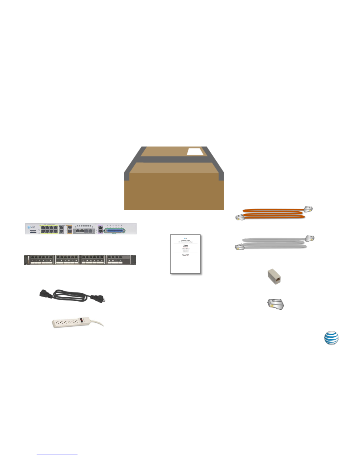
The following components are included in your router package:
What’s in the Box
2
RJ11 modem cable
Labelled ISE644 (Qty 1)
Router power cable
RJ48 T1 Cable
Labelled ISE642-025 (Qty 1-4)
Site Documentation
Package
RJ45 T1 Loopback Plug
(Qty – 1)
RJ45 Coupler (Qty -1)
6 outlet power strip
© 2014 AT&T Intellectual Property. All rights reserved. AT&T, Globe logo and other marks are trademarks of AT&T Intellectual Property.
AT&T Business in a Box® NextGen
Base Unit Router
Analog Breakout Box with Amphenol
Cable
Note: Your solution may require other
specific telephony cables and will be provided
in the box.
Page 3
Understanding your AT&T Business in a Box® Equipment
3
© 2014 AT&T Intellectual Property. All rights reserved. AT&T, Globe logo and other marks are trademarks of AT&T Intellectual Property.
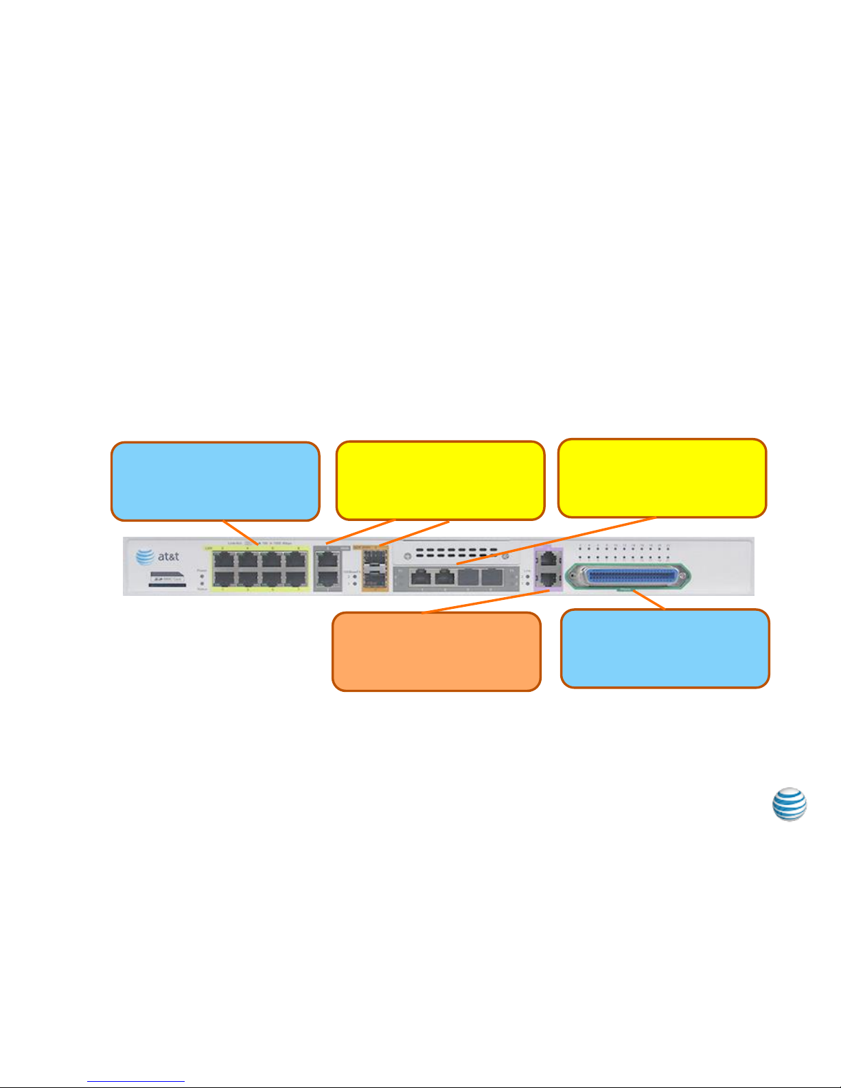
AT&T Business in a Box® NextGen Base Unit Router
Ethernet LAN Ports
1GigE ports
Ethernet WAN Ports
Electrical and Optical
T1 Ports (4)
Grey Cables from Smartjack to port.
Red cables for PRI
Survivability Ports (2)
RJ11
Analog voice port (22)
Customer Provided Cable to
Amphenol connector or to Breakout
Box.
Page 4

The AT&T Business in a Box® router may be wall mounted on a
¾” or thicker plywood backing. The unit is too heavy to be
mounted to drywall. Use the two (2) rack-mount brackets, eight
(8) bracket screws (included) and four (4) 1 ½” wood screws (not
included).
Complete the following steps:
1) Position the device so that the front panel is facing down
and apply the rack-mount brackets with bracket screws to
each side as shown in Figure 1. Rack-mount bracket
position.
2) Attach the bracket to ¾” or thicker plywood backing using
four (4) 1 ½” wood screws as shown in Figure 2. RackMount bracket on plywood backing.
Important: Cables will flow down and should be dressed using a
wire minder. The unit should be mounted high enough that the
technician can see the status lights**. See Figure 3 Installation
example.
Step 1 – Wall Mounting Instructions (optional to Rack Mounting)
4
** It is recommended, but not required that a skilled technician mount the router on the wall.
© 2014 AT&T Intellectual Property. All rights reserved. AT&T, Globe logo and other marks are trademarks of AT&T Intellectual Property.
Page 5

Step 2 - Attach Power Cord to Router and Proper Grounding
5
© 2014 AT&T Intellectual Property. All rights reserved. AT&T, Globe logo and other marks are trademarks of AT&T Intellectual Property.
Plug in power cord to router and attach customer
provided ground cable
To included
power strip
On/Off Power
Switch - Leave
powered off until
ready for service
activation
Grounding Lug –
(Customer Provided
ground cable) Connect
#10 stranded ground to
closest earth ground or
building bus bar.
Page 6

Step 3 - Connect Analog POTS line to Internal Modem
6
© 2014 AT&T Intellectual Property. All rights reserved. AT&T, Globe logo and other marks are trademarks of AT&T Intellectual Property.
Connect customer provided Analog POTS line from wall jack to the
internal modem using the provided brown RJ11 cable.
To wall jack
RJ11 modem cable
Labelled ISE644
Note: The POTS line may be used in the turn-up of your service as well as by AT&T’s Global
Customer Service Center.
Page 7

Step 3 - Connect Router to T1 Access Circuit(s)
Connect your T1 circuit(s) using the Grey T1 cable(s) to the port(s) labeled
Port 1-4.
7
T1 Cable(s) labelled ISE642
To smart jack(s)
Note: Up to 4 T1’s may be utilized. If using a single T1 then plug the T1 cable into port 1.
A second T1 should be plugged into port 2, third into port 3 and fourth into port 4.
© 2014 AT&T Intellectual Property. All rights reserved. AT&T, Globe logo and other marks are trademarks of AT&T Intellectual Property.
Page 8

Step 4 – Attach RJ45 Coupler andRJ45 Loopback plug to router
Locate the RJ45 Coupler and RJ45 Loopback Plug
8
Locate the RJ45 Coupler and RJ45 Loopback Plug included in the
shipping box. Place the Loopback plug in one side of the coupler,
remove the adhesive tape from the side of the coupler and attach to the
router. The coupler is a holder to ensure the loopback plug is easily
locatable should it be needed to troubleshoot your service.
© 2014 AT&T Intellectual Property. All rights reserved. AT&T, Globe logo and other marks are trademarks of AT&T Intellectual Property.
Page 9

Step 5 - Connect Router to your Ethernet LAN Devices
Connect your Ethernet LAN devices (PC’s, printers, servers, etc.) to the
integrated Ethernet switch or per instructions in your Site Documentation
Package.
9
Customer provide
RJ45 LAN Cable(s)
Note: If utilizing your own Ethernet switch/firewall behind the AT&T Business in a Box®
then utilize only Port 2 to interconnect.
© 2014 AT&T Intellectual Property. All rights reserved. AT&T, Globe logo and other marks are trademarks of AT&T Intellectual Property.
Page 10

AT&T Business in a Box® User Guide
AT&T Business in a Box® includes integrated IPSec VPN and Point to Point
Tunneling Protocol for remote access capabilities available with your
service. A User Guide is available to assist customers with logging into the
device using a web browser and configuring to your needs.
10
© 2014 AT&T Intellectual Property. All rights reserved. AT&T, Globe logo and other marks are trademarks of AT&T Intellectual Property.
 Loading...