

Page 1
i
BEU SYSTEM PRACTICES
AT&TCo Standard
870A 1 AND 2870A1 “TOUCH-A-MATIC*” 32 AUTOMATIC DIALER
IDENTIFICATION, INSTALLATION, CONNECTIONS, OPERATION
AND MAINTENANCE
CONTENTS
1. GENERAL . . . . . . . . . . .
2. IDENTIFICATION . . . . . . . . .
A. Design Features . . . . . . .
B. Optional Features . . . . . . .
c. Ordering Guide . . . . . . .
D. Operating Features . . . . . .
PAGE
SECTION 501-164-201
Issue 5, May 1982
,,
CONTENTS
1
3
3
3
4
5
5.0PERATION . . . . . . . . .
Record a Number Into Memory
A.
B. Change a Number In Memory .
Delete a Number From Memory
c.
Automatically Dial a Number
D.
Memory . . . . . . . .
E. LAST NUMBER DIALED Feature
. . .. .
. .
. .
. .
From
. .
. .
14
14
15
15
15
15
3. INSTALLATION . . . . . . . . . .
STANDARD INSTALLATION . . . . . .
Installation Check Procedure . . .
OPTIONAL APPARATUS INSTALLATION . .
A. D-1 80493 Kit of Parts (Dial Tone Detec-
tor and One-Touch Calling Switch) .
B. D-1 80818 Kit of Parts (Record Disable
and Dial Intermix Feature) . . . .
COMPONENT LOCATION AND ACCESS lN-
FORMATION . . . . . . . . . .
A. Power Supply Board (PSB) Terminals
B. Faceplate Removal . . . . . .
Housing Removal . . . . . . .
c.
4. CONNECTIONS
. . . . . . . . .
12
12
13
13
14
5
5
6
8
8
9
F. End-to-End Signaling (2870A 1 Only)
6. MAINTENANCE . . . . . . . . .
Trouble Analysis . . . . . . .
A.
Battery . . . . . . . . . .
B.
Memory . . . . . . . . . .
c.
Dial . . . . . . . . . . .
D.
line Sensing Relay Printed Wiring Board
E.
Assembly . . . . . . . . .
F.
Faceplate (conversion from 870A2 or
2870A2 to 870B1 or 2870B1 ) . .
1, GENERAL
1.01
This section contains information
870A1
(rotary)
and
the
16
16
16
16
16
17
17
18
on the
2870A1
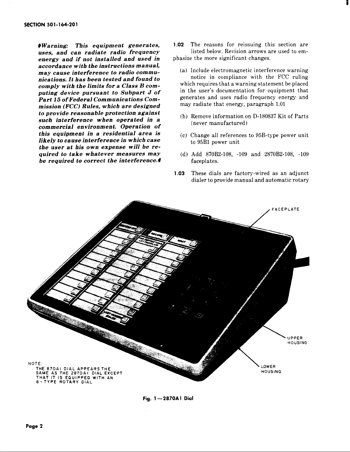
(TOUCH-TONEt service) Fig. 1 dials.
*Registered Trademark
Company.
of American Telephone and Telegraph
Not for use or disclosure outside the
Bell System except under written agreement
Printed in U.S.A.
tRegistered Service Mark of American Telephone and Telegraph
Company.
NOTICE
Page 1
Page 2
SECTION 501-164-201
#Warning:
uses, and can radiate radio frequency
energy and if not installed and used in
accordance with the instructions manual,
may cause interference to radio communications. It has been tested and found to
comply with the limits for a Class B computing device pursuant to Subpart J of
Part 15 of Federal Communications Com-
mission (FCC) Rules, which are designed
to provide reasonable protection against
such interference when opera ted in a
commercial environment. Opera tion of
this equipment in
likely to cause interference
the user at his own expense will be required to take whatever measures may
be required to correct the interference.0
This equipment genera tes,
a residential area is
in which case
1.02 The reasons for reissuing this section are
listed below. Revision arrows are used to em-
phasize the more significant changes.
(a) Include electromagnetic interference warning
notice in compliance with the FCC ruling
which requires that a warning statement be placed
in the user’s documentation for equipment that
generates and uses radio frequency energy and
may radiate that energy, paragraph 1.01
Remove information on D-180837 Kit of Parts
(b)
(never manufactured)
Change all references to 95B-type power unit
(c)
to 95B1 power unit
Add 87OB2-108, -109 and 287OB2-108. -109
(d)
faceplates.
1.03
These dials are factory-wired as an adjunct
dialer to provide manual and automatic rotary
/ FACEPLATE
Page 2
—2870A1 Dial
Fig. 1
Page 3
1SS5, SECTION 501-164-201
(870A1 ) or TOUCH-TONE (2870A1) dialing service
when interfaced with a multiline or nonmodular tele-
phone set or console. For modular single line application, the 870B1M or 2870B1M dials should be
provided.
1.04 These dials are shipped from the factory in the
Ivory (-50) housing only. However, housings
are available in additional colors per paragraph
2.09.
2. IDENTIFICATION
2.o1
These dials provide manual dialing plus auto-
matic dialing of 31 frequently called numbers,
and a LAST NUMBER DIALED scratch pad memory.
A. Design Features
2.o2
The following are design features:
●
Integrated circuit memory.
●
Memory buttons from which to select preprogrammed telephone numbers for automatic
dialing.
●
Capability to record and automatically dial
31 telephone numbers of up to 15 digits each.
●
Last number manually dialed memory.
● Plug-in battery.
● Capability to pause for subsequent dial tones
during automatic dialing (WAIT input).
B. Optional Features
2.03
The following are optional features.
(a) Decorative Faceplate.
(b) Speakerphone: These dials interface with tele-
phone sets using either 3B (MD) or 4A speak-
erphone systems.
(c) Dial Tone Detector: Automatically starts
dialer when precise TOUCH-TONE service
dial tone (350 Hz and 440 Hz) is present.
(d) One-Touch Calling Depressing one memory
button will automatically turn on speaker-
phone, detect dial tone, and dial complete number.
Note: All dial tones encountered in the pro-
cess of placing a call must be precise TOUCHTONE service dial tone (350 Hz and 440 Hz) if
the call is to be completed automatically.
(e) D-180818 Kit of Parts provides the following
features.
(1) Record Disable Only: Turns off recording
feature to prevent accidental erasures of
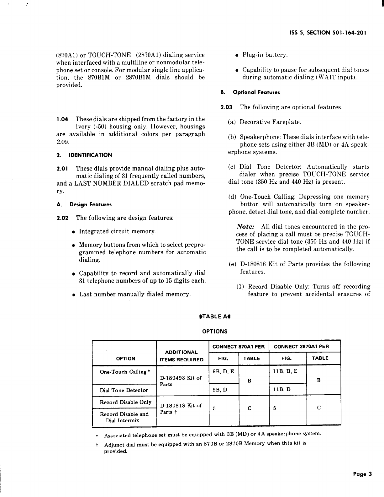
$TABLE At
OPTIONS
I
OPTION
One-Touch Calling *
ADDITIONAL
CONNECT 870A1 PER
ITEMS REQUIRED
B180493 Kit of
CONNECT 2870A1 PER
FIG.
llB, D, E
XG--lB
5
c
5
=“:0’18”t0f
*
Associated telephone set must be equipped with 3B (MD) or 4A speakerphone system.
t Adjunct diaf must be equipped with an 870B or 2870B Memory when this kit is
provided.
I
] TABLE I
I I
c
Page 3
Page 4
SECTION 501-164-201
previously stored numbers. No recording possible except for LAST NUMBER DIALED memory which will store digits dialed manually from
adjunct dial.
(2) Record Disable and Dial Intermix: Same as
record disable feature plus.
(a) Allows digits dialed with manual dial
and from memory to be intermixed without having to depress the RECORD OFF button.
(b) Disables the LAST NUMBER DIALED
feature.
2.04 All options are implemented by the following.
● Wiring changes in the applicable dial.
●
Dial, 8EA-119
●
841382880 Line Sensing Printed Wiring
Board Assembly
●
Cord, Mounting, D1OU-87
●
Cord, Power, M2SL-87
●
Battery, KS-20390L4
●
Memory, 870B
●
841382617 Power Supply Printed Wiring
Board (PSB) Assembly
●
840393672 Directory Sheet Set
●
Booklet, Instruction, Subscriber, SIB-2481B
● Wiring changes in the telephone set or con-
sole to which the dial is an adjunct.
● Installation of appropriate additional items.
Ordering Guide
C.
2.05
Either of these dials maybe ordered complete
and ready to install as:
● Dial, 870A1-50 (rotary service)
● Dial, 2870A1-50 (TOUCH-TONE service).
2.06 The following must be ordered separately:
● Unit, Power, 95B1 (required for operation
the automatic dialing feature)
Note: One power unit is required for each
adjunct dial.
● Decorative Faceplate, see paragraph 2.09.
2.07
The 870A1-50 dial may be ordered in its com-
ponent parts as follows:
(a)
Housing, Lower, 870ADJ1-50
Housing, Upper, 870A1U-50
(b)
Faceplate, 870B1-122 (Matte Aluminum)
(c)
2.08
The 2870A1-50 dial may also be ordered in its
component parts as follows:
(a)
Housing, Lower, 870ADJ1-50
(b)
Housing, Upper, 870A1U-50
(c)
Faceplate, 2870B1-122 (Matte Aluminum)
(d)
841381965 Dial Base (includes the following):
●
Dial, 35AG3A
841382880 Line Sensing Printed Wiring
●
Board Assembly
●
Cord, Mounting, D1OU-87
of
●
Cord, Power, M2SL-87
●
Battery, KS-20390L4
●
Memory, 2870B
●
841382385 Power Supply Printed Wiring
Board (PSB) Assembly
●
840393672 Directory Sheet Set
●
Booklet, Instruction, Subscriber, SIB-2481B.
2.o9 Optional apparatus (order as required) is as
follows:
841382575 Dial Base (includes the following):
(d)
Page 4
● Housing, Lower, 870ADJ1-(see Note 1)
Page 5
1SS5, SECTION 501-164-201
Housing, Upper, 870Al U-(see Note 1)
Faceplate, Decorative, 870B1-(see Note 2),
2870B1-(see Note 2) or 870B2-(see Note .2),
2870B2-(see Note 2)
Cord, Mounting, D1OY-W (required when
adjunct dial connected to some MET sets and
some COM-KEY* key telephone systems)
Kit of Parts, D-180493 (Dial Tone Detector
and One-Touch Calling Switch)
Kit of Parts, D-180818 (Record Disable and
Dial Intermix) (see Note 3)
Note 1: Color suffix as follows: Black (-03),
Green (-51), White (-58), and Light Beige (-60).
Note 2: Color suffix as follows: Teak
Woodgrain (-108) or Walnut Woodgrain (-109).
$B2-type is the same as B1-type faceplate except woodgrain runs in the opposite direction.
B2-type faceplates are compatible with MET
sets and COM KEY 416 key telephone system.q
Note 3: The D-180818 Kit of Parts can only
be used on dials equipped with an 870B or 2870B
Memory.
and enables the memory circuits to store telephone numbers.
●
RECORD OFF button (nonlocking), when
momentarily depressed extinguishes the
RECORD lamp, indicating that the dialer is
switched out of the record mode.
●
WAIT button (nonlocking), when momentarily depressed during recording operation,
enters a code into memory to initiate a halt
in the automatic dialing sequence [used
where access digit(s) required].
INSTALLATION
3.
STANDARD INSTALLATION
Warning:
or power unit until all connections and
modifications are completed. Take ex-
treme care not to damage the exposed
components, circuit, etc. when the set is
opened.
3.01
Connect the adjunct dial to the telephone set
Do not plug in either battery
using the D10U~87 or D1OY-5Omounting cord.
Refer to Fig. 6 and 7 for basic interface connections
and to Tables D through G for specific connections.
D.
Operating Features
O Operating features (Fig. 1) are as follows.
2.1
● Dial.
● 32-button array of low force, low travel
nonlocking memory buttons arranged in
three columns. Left and right columns have
eleven buttons, center column has ten buttons.
● LAST NUMBER DIALED button located in
lower right corner of memory array, when
momentarily depressed, automatically
redials the last number manually dialed from
the adjunct dial.
● RECORD button (nonlocking), when momen-
tarily depressed, lights the RECORD lamp
*Registered Trademark of American Telephone and Telegraph
Company.
3.02 The dials are shipped from the factory with
the battery disconnected. After all wiring
changes and modifications have been completed, con-
nect the battery by tilting the adjunct dial up and
inserting the battery plug into the mating jack.
Note: Write date of battery installation on
label provided.
Danger 1:
retaining clamp, if used, to ac outlet using
outlet cover screw BEFORE attempting
to install 995B14 power unit. The POwer
unit and any other cord plugged into the
ac outlet should always be unplugged
completely from the outlet BEFORE attempting attach or remove the retaining
clamp. This will prevent the possibility y of
a loosened retainer clamp or metallic
outlet cover making contact with the ac
prongs of the power unit when partially
withdrawn from outlet. Do not use retaining clamp on outlets where the cover
For safety, securely attach
Page 5
Page 6
SECTION 501-164-201
mounting screw holds the duplex outlet
in the box.
Danger 2:
and dress leads connecting to 10w voltage
output terminals of495B14 power unit to
assure that inadvertent connection to
conducting surfaces or other power
source does not occur. If more than one
power unit is plugged into
ceptacle power strip, there must be
least one inch separation between power
units. Only UL listed receptacle power
strips with adequate power rating shall
be used. Use of a continuous terminal
power strip that allows the secondary
output terminals of the power unit to be
in close proximity to the ac line source is
not recommended.
Care should be taken to trim
a multiple re-
at
RECORD LAMP
. . . -—
3.03 Connect the M2SL-87 power cord to the power
unit and plug the power unit into an ac outlet
not controlled by a switch (continuous ac power is
required).
Note: The power unit must be located no
closer than 1-1/2 feet from the dial in order to
prevent a potential noise condition.
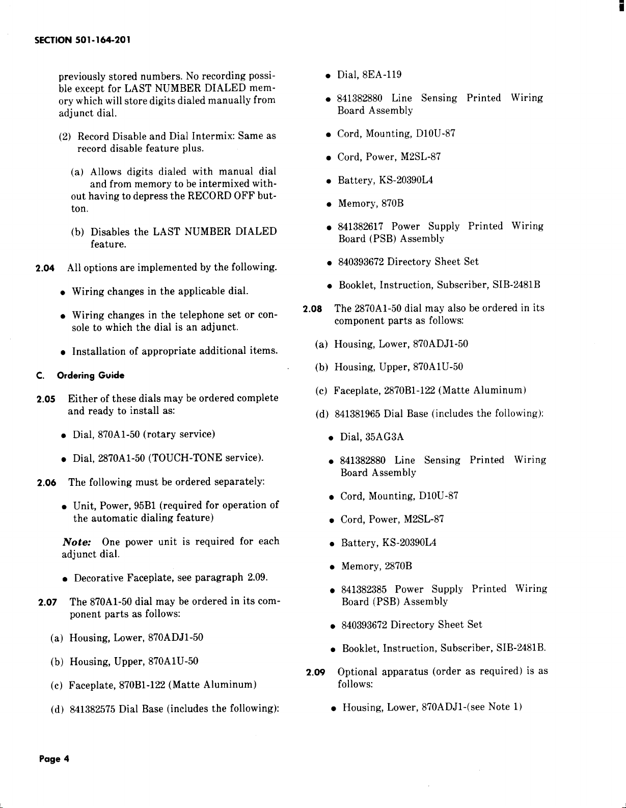
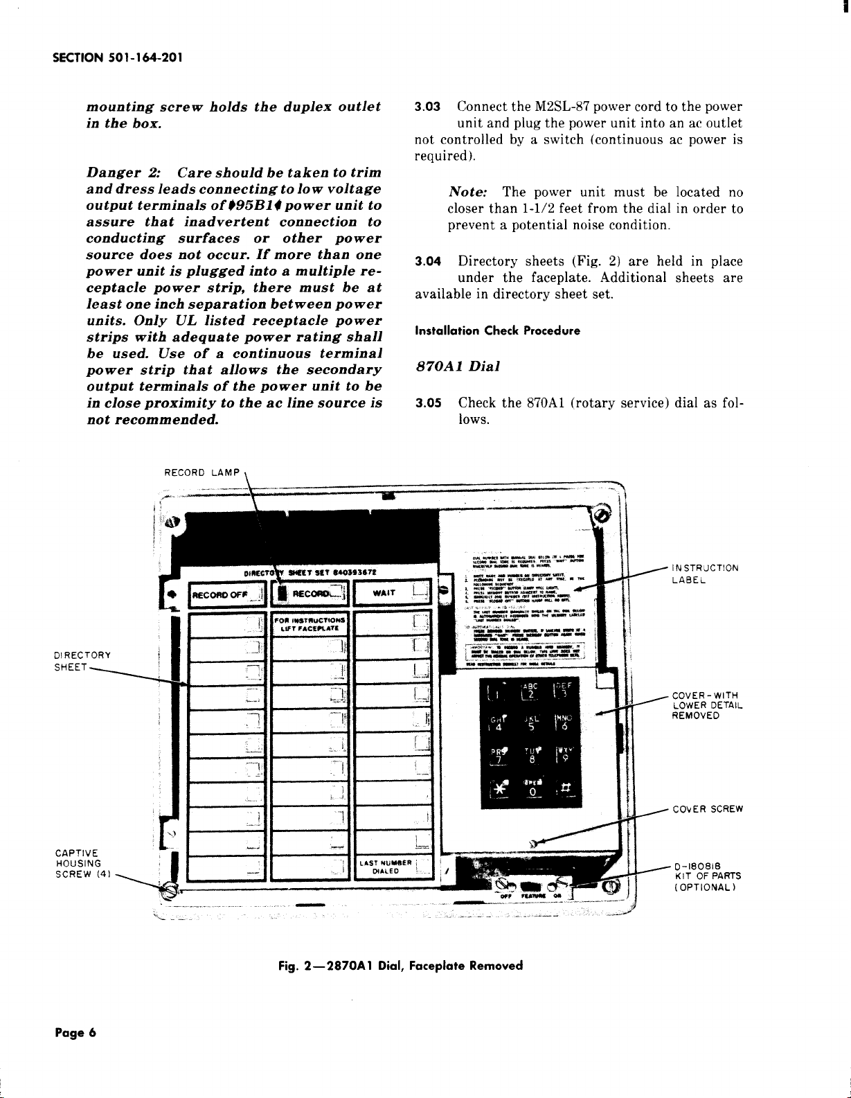
3.o4 Directory sheets (Fig. 2) are held in place
under the faceplate. Additional sheets are
available in directory sheet set.
Installation Check Procedure
870A 1 Dial
3.05 Check the 870A1 (rotary service) dial as fol-
lows.
-
1
DIRECTORY
‘HEET4
CAPTIVE
HOUSING
SCREW (41 ,
%)
.-
r
J
i
.. —-.
.,. --,------
01~,.&lp . . - --
A -.
.. —...-. -—-----—-- ——-—”— -—.-
---- .
Fig. 2—2870A 1 Dial, Faceplate Removed
‘a m-w
.#=’lTl
_.-—.
t
----
II
4
INSTRUCTION
LABEL
COVER- WITH
LOWER DETAIL
REMOVED
COYER SCREW
D-18081E3
KIT OF PARTS
(OPTIONAL)
Page 6
Page 7
1SS5, SECTION 501-164-201
(1) Check operation of line sensing circuit per the
following tests. (Refer to Part 5 for operation. )
In case of failure, refer to Table H (Trouble Analysis).
(a) With telephone handset on-hook, momen-
tarily depress RECORD button. RECORD
lamp should light.
(b) Lift telephone handset off-hook. RECORD
lamp should be extinguished.
(2) Using the telephone set dial, manually dial a
known number to check that the telephone set
operates correctly.
(3) For the adjunct dial, perform dial speed test
as follows.
(a) Obtain dial tone.
(b) Dial code number for dial speed test.
(c) After dial tone is heard again, manually
dial digit O.One of the following audible signals will indicate how the dial meets the requirements of the test.
(1) Audible ringback: dial speed satisfacto-
ry.
(2) Rapidly interrupted dial tone: dial speed
fast.
(3) Slowly interrupted dial tone: dial speed
slow.
(4) With the telephone handset on-hook, use the
dial on the adjunct to record known telephone
numbers, storing consecutive digits of the numbers in sequential memory locations. Fill all memory locations except LAST NUMBER DIALED
and the location immediately above it [paragraph
5.01 (4) through (7)].
(5) Automatically dial the telephone numbers
stored in Step (4) by momentarily depressing
the memory buttons in the same sequence in which
the digits were recorded. Verify that the digits
thus dialed produce the expected telephone num-
bers.
ory location immediately above LAST NUMBER
DIALED location [paragraph 5.01 (4) through (7)].
(7) Momentarily hang up handset and then auto-
matically dial the number recorded in Step (6).
(8) Go off-hook and from the adjunct, manually
dial a known telephone number.
Note: If a pause for second dial tone is re-
quired, dial the access digit(s). After the RECORD lamp relights, depress the WAIT button
then dial the telephone number.
(9) Momentarily hang up handset and then auto-
matically redial the number [dialed in Step
(8)] by depressing the LAST NUMBER DIALED
button.
Note: The dial should stop dialing if it
reaches a stored WAIT input. Depress the
LAST NUMBER DIALED button again and the
remaining digits should be dialed.
R
The battery and power unit must be
connected a minim urn of five min-
utes before doing Step (10).
K
(10) Momentarily disconnect the power unit (for
5 to 10 seconds). After reconnecting power
unit, momentarily depress memory buttons in
same sequence in which digits were recorded in
Step (4). Verify that the correct telephone number
is dialed.
(11) Dial the appropriate code for ring-back to
test the telephone set ringer.
(12) If equipped with one-touch calling option, (D-
180493 Kit of Parts and speakerphone), and
with set in on-hook condition, depress the memory
button used in Step (6). The speakerphone should
turn on, dial tone should automatically be detected, and the stored number should be automatically
dialed.
2870A1 Dial
3.06 Check the 2870A1 (TOUCH-TONE service)
dial as follows.
(6) Go off-hook and use the dial on the adjunct to
record a known telephone number into mem-
(1) Check operation of the line sensing
the following tests. (Refer to Part 5 for opera-
circuit per
Page 7
Page 8
SECTION 501-164-201
tion. ) In case of failure, refer to Table I (Trouble
Analysis).
(a) With the telephone handset on-hook, mo-
mentarily depress the RECORD button.
RECORD lamp should light.
(b) Lift telephone handset. RECORD lamp
should be extinguished.
(2) Using the telephone set dial, manually dial a
known number to check that telephone set
operates correctly.
(3) With the telephone handset on-hook, use the
dial on the adjunct to record digits 1 through
O in consecutive memory locations, storing one
digit per memory. Fill all memory locations except
LAST NUMBER DIALED and the memory location immediately above it [paragraph 5.01 (4)
through (7)].
(4) Lift handset off-hook and record CO dial test
and ringer circuit number into memory location immediately above LAST NUMBER DIALED
location [paragraph 5.01 (4) through (7)]. After
depressing RECORD OFF button, and when dial
test circuit is ready, test dial frequencies by manually dialing digits 1 through O into the test circuit.
(5) Momentarily hang up handset and then auto-
matically redial the test circuit number recorded in Step
(4) by depressing button
immediately above LAST NUMBER DIALED button and proceed as follows:
(a) Depress LAST NUMBER DIALED button.
Digits 1 through O will be automatically
dialed into test circuit. Verify that correct sig-
nal is returned from test circuit.
telephone set dial, manually dial a known num-
ber to check that the telephone set operates correctly.
Note: With ac power removed, the adjunct
dial is inoperative.
(6) Reconnect the power unit, momentarily de-
press the LAST NUMBER DIALED button.
Verify that the number dialed is the same as that
recorded in Step (4).
(7) If equipped with one-touch calling option (D-
180493 Kit of Parts and speakerphone), and
with the telephone set in on-hook condition, depress the memory button previously used in Step
(4). The speakerphone should turn on, dial tone
should automatically be detected, and the stored
number should be automatically dialed.
OPTIONAL APPARATUS INSTALLATION
A.
D-180493 Kit of Parts (Dial Tone Detector and OneTouch Calling Switch)
3.07
Install as follows.
(1)
Remove the housing (paragraph 3.11) and ac-
cess PSB terminal board (paragraph 3.09).
(2)
Insert the dial tone detector board assembly
from the back of the dial, such that the two
tabs on the board assembly fit into the slots in the
chassis (Fig. 3).
(3) Insert the self-threading screw through the
side of the chassis to secure the board in posi-
tion.
(4) Mount the one-touch calling switch below the
dial with the two screws provided.
(b) Momentarily depress the memory buttons
used in Step (3) in the same sequence in
which the digits were recorded. Verify that the
correct signal is returned from the test circuit.
R
The battery and power unit must be
connected a minim urn of five minutes before doing Step (c).
K
(c) Disconnect the power unit from the ac out-
let. With the handset off-hook and using the
Page 8
Note: If the switch for D-180818 Kit of Parts
is already present, the one-touc!l calling switch
cannot be installed. The terminals on the PSB
to which the one-touch switch should have been
connected (Table B) shall be strapped together.
(The one-touch calling option can no longer be
disabled by the subscriber. )
(5) Connect per Table B.
(6) Break off the detail at the bottom of the cover
(Fig. 4) and
trim edge as required.
Page 9
1SS5, SECTION 501-164-201
Verify correct operation of option.
(7)
(8) Reassemble.
D-1808 18 Kit of Ports (Record Disable and Dial lnter-
B.
mix Feature)
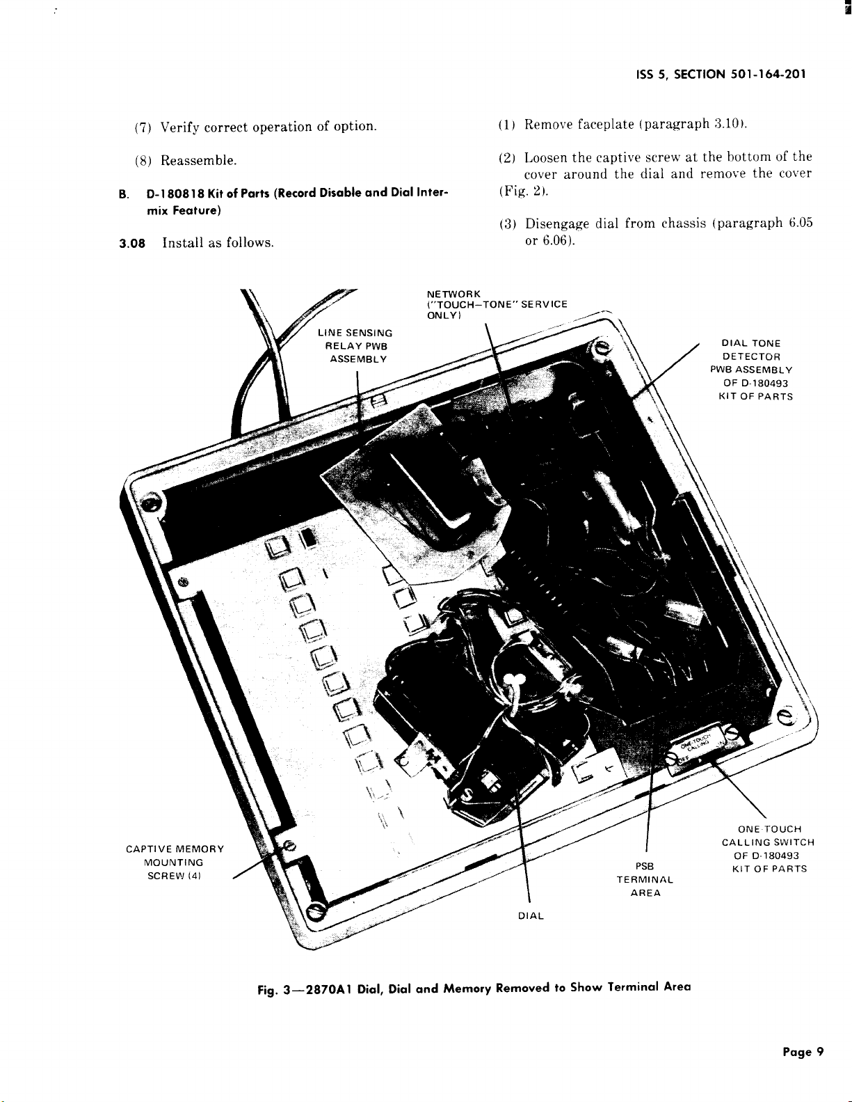
3.08 Install as follows.
(1) Remove faceplate (paragraph 3.10)
(2) Loosen the captive screw at the bottom of the
cover around the dial and remove the cover
(Fig. 2).
(3) Disengage dial from chassis (paragraph 6.05
or 6.06).
Fig. 3—2870A1 Dial, Dial and Memory Removed to Show Terminal Area
Page 9
Page 10

SECTION 501-164-201
M h$l L
;~s FOR
809!8 KIT
PARTS
= MEMORY
“AI L‘0 R
SWITCHES
Fig. 4—2870A 1 Dial, Internal View
(4) Loosen the four captive Memory mounting
18019;1 Kit of Parts) is already present it shall
screws (Fig. 3). be removed and the PSB terminals to \vhich it
~vas connected (Table B) shall be strapped to-
Rotate the left edge of the Memory upward as
(5)
gether. (The one-touch calling option can no
shown in Fig. 4 longer be disabled by the subscriber. )
Note: If existing memory is 8’70A or 2870A, it
(7)
must be replaced with 870B or 28’70B, respectively. Carefully repack existing memory to en-
Connect switch lead connectors to terminal
posts on memory board per T:ihle C.
sure recovery.
(8)
(6) Mount switch below dial with the two scre;vs
pro~’ided,
Note: If the one-touch calling s~vitch (D-
Set FE,ITURE s~vitch to OFF position and
v(’rify that ~lia] operates in normal manner.
. .Nomh’rs tan be recorded into memory
Page 10
Page 11
1SS5, SECTION 501-164-201
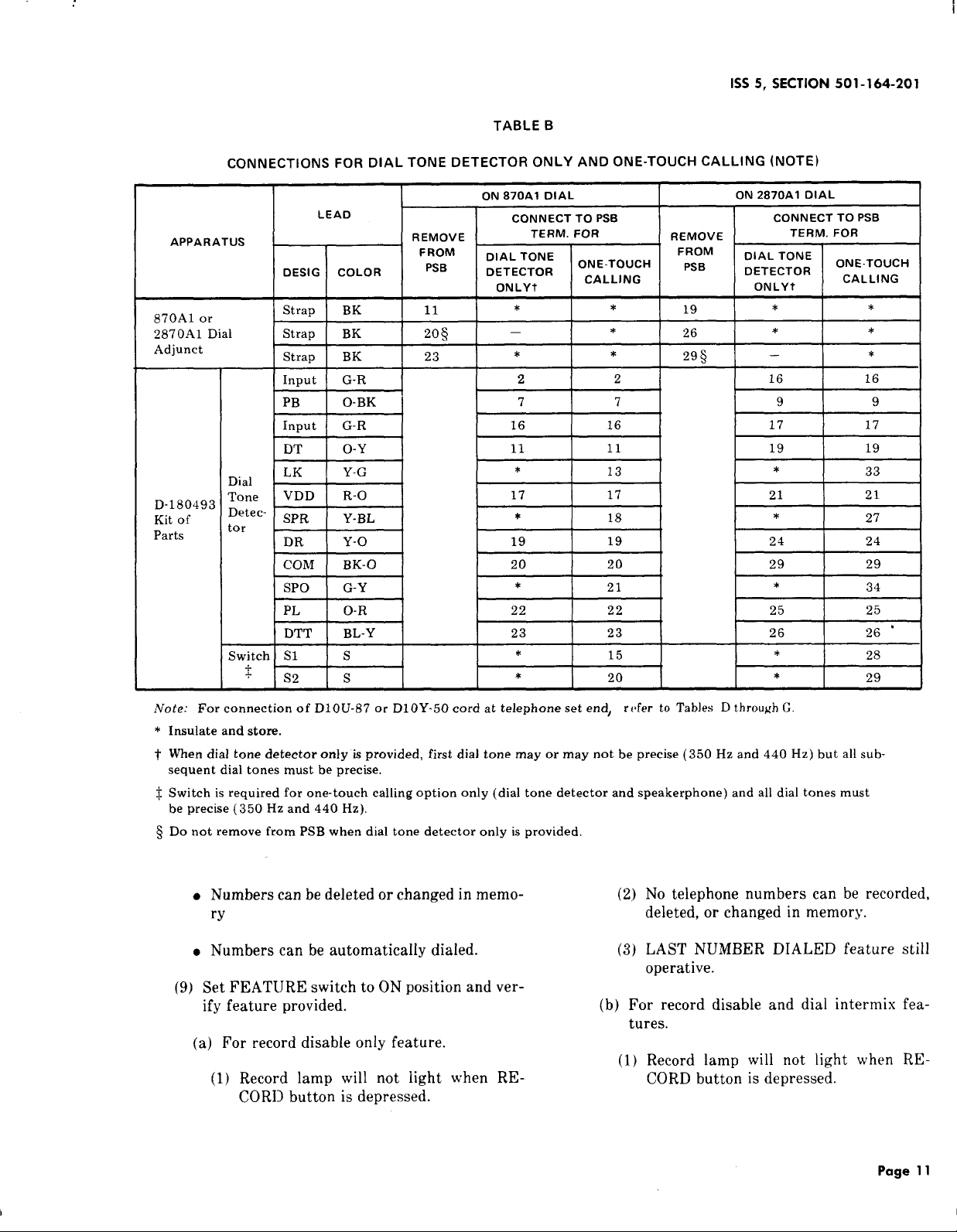
TABLE B
CONNECTIONSFOR DIAL TONE DETECTOR ONLY AND ONE-TOUCH CALLING (NOTE)
APPARATUS
870A1 or
2870A1 Dial
Adjunct
D-180493
Kit of
Parts
DESIG COLOR DETECTOR
Strap BK
I StraD I BK
Strap BK 23
Input
PB
Input
DT
Dial ‘K
Tone
‘etector
VDD R-O 17
SPR
DR Y-o 19
conl
SPO G-Y
PL
DTT BL-Y 23
Switch S1
+
+
S2
ON 2870A1 DIAL
TERM. FOR
DIAL TONE
DETECTOR
ONLYt
*
—
9 9
LEAD
G-R
O-BK
ON 870A1 DIAL
CONNECT TO PSB CONNECT TO PSB
REMOVE
FROM
PSB
11
1206 I - I * 126 / * I * ]
.
TERM. FOR
DIAL TONE
ONLYt
*
ONE-TOUCH
CALLING
*
* *
2
2 16
REMOVE
FROM
PsB
19
295
7 7
G-R 16 16 17 17
o-Y
Y-G
Y-BL
BK-O
O-R
s
s
11
*
*
20 20
*
22 22
*
*
11
13
17
18
19
21
23
20
15
19 19
*
21
*
24
29
*
25 25
26 26 “
*
*
ONE-TOUCH
CALLING
*
*
16
33
21
2’7
24
29
34
28
29
Note: For connection of D1OU-87 or D1OY-5O cord at telephone set end, refer to Tables D through G
* Insulate and store.
~ When dial tone detector only is provided, first dial tone may or may not be precise (350 Hz and 440 Hz) but all sub-
sequent dial tones must be precise.
Switch is required for one-touch calling option only (dial tone detector and speakerphone) and all dial tones must
f.
be precise (350 Hz and 440 Hz).
$ Do not remove from PSB when dial tone detector only is provided.
No telephone numbers can be recorded,
● Numbers can be deleted or changed in memo-
ry
. Numbers can be automatically dialed.
(2)
deleted, or changed in memory.
LAST NUMBER DIALED feature still
(3)
operative.
(9) Set FEATURE switch to ON position and ver-
ify feature provided.
(b) For record disable and dial intermix fea-
tures.
(a) For record disable only feature.
(1) Record lamp will not light when RE-
(1) Record lamp will not light when RE-
CORD button is depressed.
CORD button is depressed.
Page 11
Page 12
SECTION 501-164-201
(2) No
telephone numbers can be recorded,
deleted, or changed in memory.
(3) Manually and automatically dialed digits
may be intermixed. (Depression of RE-
CORD OFF button not required. )
(4) LAST NUMBER DIALED feature dis-
abled.
(10) Reassemble adjunct dial.
COMPONENT LOCATION AND ACCESS INFORMATION
Danger: When it is necessary to access
component parts of terminal areas, ac
power must be disconnected.
Power Supply Board (PSB) Terminals
A.
3.09
To access the terminal field on the power sup-
ply board, proceed as follows.
(1)
Disconnect power unit from ac outlet.
(2)
Remove the faceplate (paragraph 3.10).
Loosen the captive cover screw at the bottom
(3)
of the cover around the dial (Fig. 2).
Remove the cover.
(4)
Loosen the two captive dial mounting screws.
(5)
Note: On units with metal dial brackets, the
screws will have to be removed.
Page 12
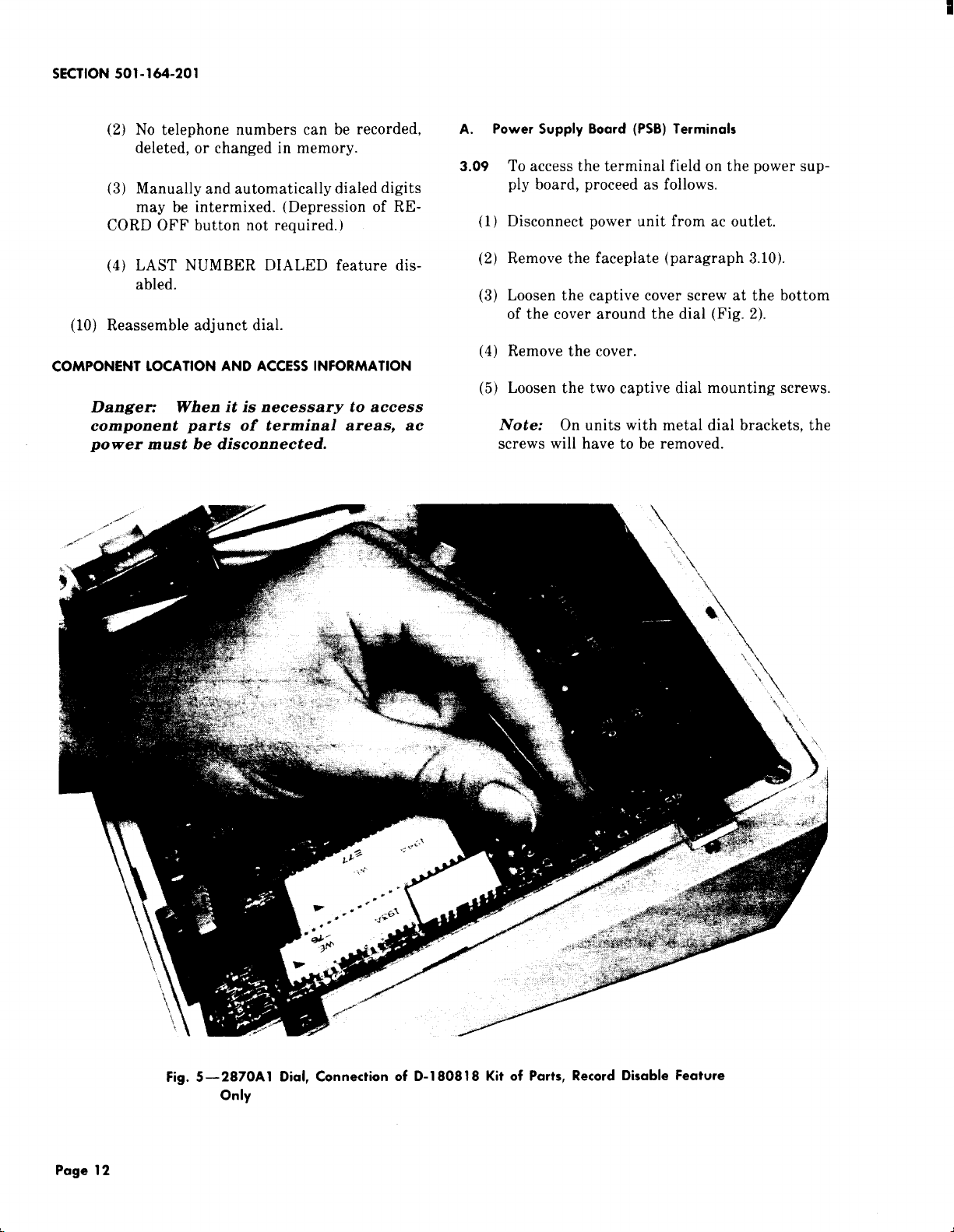
Fig. 5—2870A 1 Dial, Connection of D-180818 Kit of Parts, Record Disable Feature
Only
Page 13
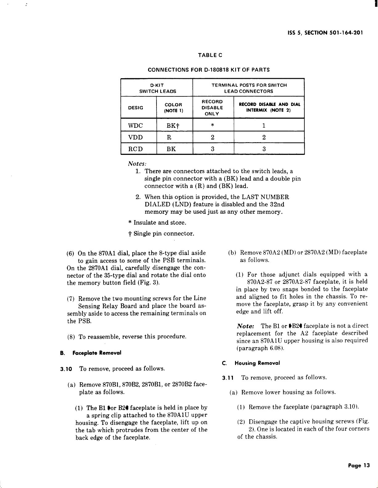
TABLE C
CONNECTIONS FOR D-180818 KIT OF PARTS
I
1SS5, SECTION 501-164-201
D-KIT
I
(6) On the 870A1 dial, place the 8-type dial aside
to gain access to some of the PSB terminals.
On the 2870A1 dial, carefully disengage the connector of the 35-type dial and rotate the dial onto
the memory button field (Fig. 3).
(7) Remove the two mounting screws for the Line
Sensing Relay Board and place the board assembly aside to access the remaining terminals on
the PSB.
(8) To reassemble, reverse this procedure.
Faceplate Removal
B.
SWITCH LEADS
DESIG
WDc
VDD
RCD BK 3
Notes:
1. There are connectors attached to the switch leads, a
single pin connector with a (BK) lead and a double pin
connector with a (R) and (BK) lead.
2. When this option is provided, the LAST NUMBER
DIALED (LND) feature is disabled and the 32nd
memory may be used just as any other memory.
* Insulate and store.
~ Single pin connector.
COLOR
(NOTE l)
BKf’
R 2
I
TERMINAL POSTS FOR SWITCH
LEAD CONNECTORS
RECORD
DISABLE
ONLY
*
RECORD DISABLE AND DIAL
INTERMIX (NOTE 2)
(b) Remove 870A2
as follows.
(1) For those adjunct dials equipped with a
870A2-87 or 2870A2-87 faceplate, it is held
in place by two snaps bonded to the faceplate
and aligned to fit holes in the chassis. To re-
move the faceplate, grasp it. by any convenient
edge and lift off.
Note: The B1 or $B24 faceplate is not a direct
replacement for the A.2 faceplate described
since an 870A1U upper housing is also required
(paragraph 6.08).
I
1
2
3
MD
or 2870A2 (MD) faceplate
3.10
To remove, proceed as follows.
(a) Remove 870B1, 870B2, 2870B1, or 2870B2 face-
plate as follows.
(1) The B1 ~or B24 faceplate is held in place by
a spring clip attached to the 870A1U upper
housing. To disengage the faceplate, lift up on
the tab which protrudes from the center of the
back edge of the faceplate.
c. Housing Removal
3.11
To remove, proceed as follows.
(a) Remove lower housing as follows.
(1) Remove the faceplate (paragraph 3.10).
(2) Disengage the captive housing screws (Fig.
2). One is located in each of the four corners
of the chassis.
Page 13
Page 14
SECTION 501-164-201
(3) Separate the housing from the adjunct dial
base while feeding the two cords through
hole in bottom of housing.
(4) Before replacing the housing, lift the ad-
junct to check that the shoulders of the battery jack are against the two chassis tabs.
Misalignment may cause the bottom of the
housing to bow.
(b) Remove upper housing as follows.
(1) Remove the faceplate (paragraph 3.10).
(2) Disengage the captive housing screws. One
is located in each of the four corners of the
upper housing (Fig. 2).
(3) Pull the upper housing away from the chas-
sis as each housing screw is backed out. This
will separate the upper housing from the chassis.
Note: If the upper housing is being replaced,
it will be necessary to remove the housing
screws.
(4) To reassemble, reverse procedure.
4. CONNECTIONS
4.o1
Typical interface connections for the basic
870A1 and 2870A1 dials are shown in Fig. 6.
4.02 Typical interface connections for the 870A1
and 2870A1 dials to provide the one-touch call-
ing feature are shown in Fig. 7.
4.o3 Connections for the adjunct dial to a selected
variety of telephone sets and consoles may be
found in the following tables:
●
Table D–870A1 Dial Connections to Telephones
●
Table E–2870A1 Dial Connections to Telephones
●
Table F–870A1 Dial Connections to Consoles
4.o5
Adjunct dial connections are shown in Fig. 9
for the 870A1 dial and in Fig. 11 for the
2870A1 dial.
4.06 Partial functional schematics are shown in
Fig. 10 for the 870A1 dial and in Fig. 12 for the
2870A1 dial.
OPERATION
5.
A. Record a Number Into Memory
Note: If equipped with the D-180818 Kit of
Parts, switch must be in the OFF position.
5.01 To record, only the dial of the adjunct may be
used. Digits manually dialed on the associated
telephone set will not be recorded into memory.
(1) Remove the faceplate (paragraph 3.10).
(2) Write or type the desired name and telephone
number for a selected memory button on the
associated position of the directory sheet.
(3) Replace the directory sheet and faceplate.
(4) Depress the RECORD button. The RECORD
lamp will light. (A number can be called and
recorded simultaneously by lifting handset before
depressing the RECORD button.)
(5) Depress the specific memory button adjacent
to the desired telephone number listed on the
directory sheet.
(6) Using the adjunct dial, manually dial the de-
sired telephone number.
Note: If an access code and pause for second
dial tone is required, perform Steps (a) through
(c).
(a) Dial the access digit(s).
(b) After the RECORD lamp lights, push the
WAIT button. (The WAIT entry counts as
one digit. )
●
Table G–2870A1 Dial Connections to Consoles.
4.04 Refer to Table A for connection references for
all options.
Page 14
(c) Using the adjunct dial, manually dial the
telephone number.
Note: A number up to 15 digits in length may
be recorded. The RECORD lamp will go out
Page 15
1SS5, SECTION 501-164-201
I
momentarily as each digit is dialed. If exactly
15 digits are recorded, the RECORD lamp will
go out and stay out, indicating that the dialer
has been reset. If a memory button has not been
depressed, the RECORD lamp will go out when
the first digit is dialed and recording operation
will be voided.
(7) Depress the RECORD OFF button if less than
15 digits are recorded. The RECORD lamp wi!l
go out. The dialer will be reset. The number is now
stored in the selected memory. The dialer will also
be reset by a switchhook or speakerphone operation.
Change a Number In Memory
B<
lVote: If equipped with the D-180818 Kit of
Parts, switch must be in the OFF position.
5.02 Whenever a new number is recorded in a pre-
viously used memory position, it will automat-
ically replace the previously stored number.
Delete a Number From Memory
c.
Note: If equipped with the D-180818 Kit of
Parts, switch must be in the OFF position.
equipped with speakerphone, and adjunct dial
equipped with dial tone detector), simply depress
the memory button.
E.
LAST NUMBER DIALED Feature
Note: If equipped with the D-180818 Kit of
Parts, and dial intermix feature is provided,
switch must be in the OFF position.
5!05
The adjunct dial automatically records into
the LAST NUMBER DIALED position (Fig.
any number called using the dial of the adjunct. Each
number in the LAST ,NUMBER DIALED position is
automatically replaced by the next number manually
dialed. Although the unit is recording, the RECORD
lamp does not light at any time during this operation.
5.06 Operation of LAST NUMBER DIALED feature is as follows.
(a) If no access digit(s) are required, proceed as
follows
(1) Go off-hook on the telephone set
(2) Listen for dial tone
1 )
5.03
To delete a number, proceed as follows.
Depress the RECORD button.
(1)
(2)
Depress the memory button corresponding to
the name and number to be deleted.
(3)
Depress the RECORD OFF button.
D. Automatically Dial a Number From Memory
5.o4
To automatically dial a number, proceed as
follows.
(1) Go off-hook on the telephone set, listen for
dial tone, and depress the desired memory button. If WAIT input has been recorded, automatic
dialing will stop. When second dial tone is heard,
depress memory button again to complete auto-
matic dialing.
(2) If the adjunct dial is equipped with the dial
tone detector only, go off-hook, listen for dial
tone, and depress the memory button.
(3) If the adjunct dial is wired to provide the one-
touch calling feature (telephone set is
(3) Manually dial telephone number using the
adjunct dial
(4) To redial same number automatically, go
off-hook on telephone set, listen for dial
tone, and depress LAST NUMBER DIALED
button.
(b) If an access code and pause for second dial
tone is required, proceed as follows:
Go off-hook on the telephone set
(1)
Listen for dial tone
(2)
Dial access digit(s) using adjunct dial
(3)
After second dial tone is heard depress
(4)
WAIT button
Manaully dial telephone number using ad-
(5)
junct dial
To redial same number automatically-, go
(6)
off-hook, listen for dial tone, and depress
Page 15
Page 16

SECTION 501-164-201
LAST NUMBER DIALED button. When second
dial tone is heard, depress LAST NUMBER
DIALED button again to complete automatic
dialing.
F. End-to-End Signaling (2870A 1 Only)
s.07
For end-to-end signaling (such as data transmission), the 2870A1 dial has the capability to
intermix manual and automatic dialing.
5.08 If the one-touch calling option is provided, the
initial number must be dialed automatically
(even if the one-touch switch is in the OFF position).
This allows the dial tone detector to complete its
function. Additional numbers may then be dialed
automatically or manually if desired.
Standard Operation: If at any time, dig-
(a)
it(s) are keyed manually using the 2870A1
dial, the RECORD OFF button must be depressed
before additional digits can be dialed automatically from memory. (The RECORD lamp will not
light at any time but depressing the RECORD
OFF button will remove the dial from the LAST
NUMBER DIALED mode to allow additional automatic dialing. )
(3) Refer to Trouble Analysis Table H (8701
Table I (2870A1).
(4) If removal of adjunct dial is required, pr
as follows.
(a) Disconnect power unit from ac outle
unplug battery.
(b) Disconnect adjunct dial.
Warning: Failure to restrain PIU$
result in plug damage requiring ba
replacement t.
(c) Place battery plug sideways into hc
slot below battery pack and tape into
B. Battery
6.03
The battery has an expected life of at
years. It can be replaced without loss of:
numbers provided that commercial ac power ~
dial is continuously maintained. To replace th
tery, proceed as follows:
(1) Tilt the front of the dial adjunct up
9Dial Intermix Mode (with D-180818
(b)
Kit ofParts): 4
Manually and automatically
dialed digits may be intermixed as desired when
the FEATURE switch is in the ON position.
Note: In this mode, the RECORD button and
the LAST NUMBER DIALED feature are inop-
erative.
6. MAINTENANCE
6.01
In case of power failure, the adjunct dial is
inoperative. The battery retains the number
associated with each of the memory buttons for at
least 24 hours. If power loss exceeds 24 hours, the
numbers may have to be rerecorded.
A. Trouble Analysis
6.02 When trouble is encountered, the subsequent
procedure should be followed.
(1) Confirm improper operation either as a basic
dial or as an automatic dialer (Part 5).
(2) Check connections.
(2) Unplug the battery
(3) Loosen captive screw on the battery SUI
(4) Remove battery support
(5) Remove battery
(6) Install and check new battery (paragraph 3
or 3.06).
C. Memory
6.04 The memory may be replaced in the foil
manner.
(1) Disconnect power unit from ac outle
unplug battery.
Note: Removal of the memory or ac an
tery power results in loss of stored numt
(2) Remove the faceplate (paragraph 3.10).
(3) Loosen the four captive memory mol
screws (Fig. 3).
Pcrge 16
Page 17

,
1SS5, SECTION 501-164-201
Rotate the left edge of the memory upward as
(4)
shown in Fig. 4.
(2) Remove faceplate (paragraph 3.10).
(5) Disengage the connector(s) by pulling them
perpendicular to the printed wiring board.
(3) Loosen the captive screw at bottom of the
cover around the dial and remove the cover.
(6) Replace the memory by engaging the dial con-
nector (2870A1 only) first. The connector(s)
(4) Disengage the two dial mounting screws.
are keyed, one position is filled and should fit over
the vacant position in the row of pins. The flat
power supply cable should not be twisted.
lVote: On early units, with metal dial brack-
ets, the screws will have to be removed.
(7) Reassemble dial.
(8) Reconnect battery and power unit.
(9) Test per paragraph 3.05 or 3.06 as required.
(10) Reprogram memory (see Part 5).
D. Dial
6.05 Replace rotary dial as follows.
(1) Disconnect power unit from ac outlet and
unplug battery.
Note: Removal of ac and battery power re-
sults in loss of stored numbers.
(2) Remove faceplate (paragraph 3.10).
(3) Loosen the captive screw at bottom of the
cover around the dial and remove the cover.
(4) Remove the two dial mounting screws and set
dial aside.
(5) Disengage the four captive memory mounting
screws (Fig. 3).
(6) Gently raise the memory to a position that
permits access to the dial connector.
(7) Disengage the dial connector by carefully pull-
ing on it perpendicular to the printed wiring
board.
(8) Disengage the second dial connector from the
power supply printed wiring board.
(9) Lift the dial out.
(10) To replace with a new dial, reverse the previ-
ous steps. The connectors are keyed to orient
them relative to the pins. Observe the correct ori-
entation and do not force the connection.
(11) Reconnect battery and power unit.
(12) Reprogram memory, see Part 5.
E. line Sensing Relay Printed Wiring 8oard Assembly
(5) Remove dial leads from terminals on PSB.
(6) Remove dial.
(7) Reverse procedure to replace dial.
(9) Reprogram memory (see Part 5).
6.06 Replace TOUCH-TONE* telephone dial as fol-
lows.
(1) Disconnect power unit from ac outlet and
unplug battery.
Note: Removal of ac and battery power re-
sults in loss of stored numbers.
*Trademark of American Telephone and Telegraph Company.
6.07 RepIace as follows.
(1) Disconnect power unit from ac outlet and
unplug battery.
Note: Removal of ac and battery power re-
sults in the loss of stored numbers.(8) Reconnect battery and power unit.
(2) Remove faceplate (paragraph 3.10).
(3) Loosen the captive screw at the bottom of the
cover around the dial and remove the cover.
(4) Remove the two dial mounting screws (870A1)
or disengage (2870A1).
(5) Place the dial aside to gain access to the PSB
terminals.
Page 17/18
Page 18

1SS5, SECTION 501-164-201
(6) Remove the two mounting screws for the Line
Sensing Relay Board and move the board as-
sembly to one side.
(7) Disconnect the leads of the Line Sensing Relay
Board from associated terminals on the PSB,
and remove the board assembly.
(8) Connect the leads of the replacement Line
Sensing Relay Board to the appropriate terminals on the PSB (Fig. 9B and 9C for the 870A1 dial
or Fig. llB and llC for the 2870A1 dial).
(9) Reassemble adjunct dial.
(10) Reconnect battery and power unit.
(11) Reprogram memory, see Part 5.
F. Faceplate (conversion from 870A2 or 2870A2 to
870B1 or 287061)
6.08
Replace an 870A2-87 or 2870.42-87 faceplate
with an 870B1-87 or 2870B1-87 faceplate as
follows.
(1) Remove the A2 faceplate by lifting up on any
of its edges.
(2) Remove the four captive housing screws (Fig.
2) from the chassis.
(3) Use the four housing screws to mount the
870A1U upper housing to the chassis and
870ADJ housing. The three parts should be held
tightly together as the screws are driven.
(4) Place the two tabs located along the lower
edge of the B1 faceplate in the notches in the
lower side of the 870A1U upper housing.
(5) Lower the faceplate to rest on the memory.
The spring clip located in the center of the
upper side of the upper housing should retain the
faceplate.
Page 19
Page 19

SECTION 501-164-201
TABLE D
CONNECTIONS FOR 870A1 DIAL TO TELEPHONE SET
TEL SET
LEAD COLOR
565HK,
HKM
564HL , HLM
630DA,
DAM
631DA,
631DAM
634DA, DAM
635DA, DAM
636CA, CAM
637DA, DAM
(2) G
(2) G
W-BL Net, F
W-BL Net. F Spare 1
(2) G
(2) G Net. F Spare 1
830CMT
830CMt
830CM$
830DMt,+
830DM$
831CMt
(2) Gtt
831CM~
831CM$
831DMt,+,$
(2) Gtt
WI DM!j,!f
832-Type~
833-Type~
851B
851BT
851BM
851CM
852A
852AM
870A1M
870A2M
870AI Dial~$
872A1M G
COMMON TIP PATH
REMOVE FROM
G Net. F
CONNECT TO$$
Spare 1
LEAD COLOR
G Net. F Spare 1 G
Net. F
Spare 1 G\$$
Net. F Spare 1 G$$!i
Spare 1
BL-W$$$ 13 Spare 2
BL-W$$$
Gtt
Gtt
Net. F
8 Spare 1
G
G
16 Spare 1
Net. F
8 Spare 1
G
Net. F
Spare 1
Spare 1
Spare 1
8 Spare 1
(2) G
16
Spare 1
(’2)G Net. F Spare 1
8 Spare 1 G
(2) G
G
Net. F Spare 1 G
22 Spare 1 R
(2) G Z Spare 1
G
G
G
Net. F
t ***
2
4ttt
Spare 1
Spare 1
Spare 1
W-BL TB1 8 TB1 15
w-o
G
TB1 8
26 27
TB1 15
TB1 8 TB1 15 R PSB 9
COMMON RING PATH
REMOVE FROM CONNECT TOqq
G, G-V
9
9
Spare 2
Spare 2
13 Spare 2
13 Spare 2
13 Spare 2
W-BL 13 Spare 2
W-BL 13 Spare 2
R 6 Spare 2
R
R 6
R
R 3
(2) R 6
(2) R
(2) R
6 Spare 2
Spare 2
3 Spare 2
Spare 2
Spare 2
6 Spare 2
6 Spare 2
6 Spare 2
6
Spare 2
4 Spare 2
(2) R
R
R
R
13L-W TB1 4
R TB1 4
o-w 9
4 Spare 2
13
13
Spare 2
Spare 2
1 Spare 2
TBI 16
TB1 16
Spare 1
Net. G
Page 20
Page 20

I
I
11
w-al
Spare t Net. F
Spare 1 Net. F
Spare 1
CONNECTIONS FOR 870A1 DIAL TO TELEPHONE SET
STANDARD FUNCTIONS
I T1 ILRIRI
w-o BL-W o-w
9 Spare 2
9 Spare 2
Net. F
13
TABLE D (Contd)
D1OU-87 CORD (FROM ADJUNCT DIAL)
IMI]M2 I LK I SPO
BR-W W-BR G-w
Net. R Net. GN Net. L1
Net. GN *
Spare 2
Net. R
Net. R Net. GN 4
1SS5, SECTION 501-164-201
I
SPEAKERPHONE/ONE-TOUCH
P3
W-G
I
s-w w-s
8
*
P4
‘7
*
a
9
14
Spare 1 Net. F 13 Spare 2
Spare 1
Spare 1
Spare 1
Spare 1 Net. F
Spare 1 8 Spare 2 6
Spare 1 16
Spare 1
Spare 1
Spare 1
Spare 1
Spare 1 16 Spare 2
Spare 1
Spare 1 8
Spare 1
Spare 1 22
Spare 1
Spare 1
Net. F
Net. F
Net. F
Net. F
8 Spare 2
Net. F
8 Spare 2
Net, F
Net, F
22 Spare 2
Net. F
Spare 2
Spare 2
Spare 2
Spare 2
Spare 2
Spare 2
Spare 2 3
Spare 2
Spare 2
Spare 2
6 Spare 2
6 Spare 2
13
13
13
13
6
6
3
6
6
6
4
4
13
Net. R Net. GN 4
Net. R
Net. R Net. GN
Net. R Net. GN *
Net. R
Net. R Net. GN
Net. R Net. GN 29
Net. R Net. GN
Net. R Net. GN
Net. R Net. GN 29
.Net. R
Net. R Net. GN 29
Net. R Net. GN 29
Net. R Net. GN
Net. R Net. GN
Net. R
Net. R Net. GN 29
Net. R
Net. GN
Net, GN *
Net. GN
Net. GN 29
Net. GN
Net. L1
29
29
29
29
29
29
9
4
4
See
Fig. 8
14
14 9
* *
* *
30 24
30
30
30 24
30
.30
30 24
30
30 24
30
30 24
30
14
9
24
24
24
24
24
24
24
Spare 1 2*** Spare 2
Spare 1
T13115
TB1 15 ] TB1 8 I TB1 16 I TB1 4 I Net. R I Net. GN I PSB 27 I PSB 21
I
PSB ’26 PSB 27 PSB 9 Spare 1
TB1 15
.Itt’t
I
TB1 8
TB1 8 Net. G PSB 9 Net. R
Spare 2
!
TB1 16
13 Net. R
1 Net. R
1
TB1 4 Net. R
I
PSB 1
Net. GN
Net. GN 10
1 I 1
Net. GN
PSB 8
Net. GN PSB 13 PSB 21
20
\ PSB 27
PSB 13
PSB 21
PSB 21
PSB 3 PSB 6
PSB 3
PSB 3 PSB 6
PSB 3
=H
PSB 6
PSB 6
Page 21
Page 21

SECTION 501-164-201
i
TABLE D (Contd)
TEL SET
960A01M”
Y/l I-Type**
983-Type**
LEAD COLOR
I
FOR 870A 1 DIAL TO TELEPHONE
COMMON TIP PATH
I REMOVE FROM I CONNECT TO?+!
G
PSB-7 I PSB-14
I
LEAD COLOR REMOVE FROM CONNECT TOqq
R PSB-6 PSB-19
SET
COMMON RING PATH
I
Remove Shorting Bars
Page 22
Page 22

TABLE D (Contd)
CONNECTIONS FOR 870A1 DIAL TO TELEPHONE SET
i
1SS5, SECTION 501-164-201
I
STANDARD FUNCTIONS SPEAKERPHONE/ONE-TOUCH
LT T1 LR R1 Ml
W-BL w-o BL-W
PsFi-14 PSB-7 PSB-19 PSB-6
I
D 10U-87 CORD (FROM ADJUNCT DIAL)
M2 LK
o-w
BR-W W-BR G-W
PSB-8 PSB-20 *
Plug D1OYcord into set
SPO
W-G
* Insulate and store.
t Manufactured after 2-77 with new line switch (new line switch is identified by two additional blue leads)
+ Manufactured prior to 2-77 with new line switch.
$ Manufactured prior to 2-77 with old line switch (old line switch has no blue leads).
~ (hly CCIlines can be dialed from adjunct dial (no intercom lines).
‘“ Replace the D1O[J-87 cord in the 870A1 dial with a D1OY-5Ocord, observing same color code.
tt From line key.
~+ Each adjunct dial adds 1 db loss to the loop. 20 ma loop current is required for proper operation of unit.
$$ Spare “1s” use same spare terminal or D-161488 connector in telephone set.
~~ Spare ‘2s” use same spare terminal or D-161488 connector in telephone set.
*** Network F when using 4A speakerphone.
ttt Common tip lead from line key. Located On terminal ~ in ~~~AM sets manufactured before 3-4-77
~4~ Connect to same terminals as P3 and P4 leads from 4A speakerphone.
!N!j [f speakerphone is provided, speakerphone lead designated R1 must also be moved from 13 to spare 2.
s-w
* *
I
P3 P4
w-s
*
I
Page 23
Page 23

SECTION 501-164-201
9
TABLE E
TEL SET
LEAD COLOR
2565HK,
2565HKM
‘2630DA
2630DAM
2631DA,
2631DAM
2634DA
2634DAM
2635DA
2635DAM
2636CA, CAM
2637DA, DAM
2830CM-I’
2830CM$
Gtt
G$$
G**
W-BL
W-BL
G*+
Gt+
Gtt
Gtt
2830CM$ Gtt
2WODMt,~ Gtt
2830DM$ Gtt
2831cMt
2831CM$
2831CM!
(2) Gtt
(~) Gtt
(21 Gtt
2KHDMt,+,~ (2) Gtt
2WlDM!,!l
(2) Gtt
2XV2-Type~
2833 -Type~ (2) (;
2851B,
2x51BT,
2s51 B\l
2X.51(‘M
X+52A.
2-WA .M
2x7{).’i 1M
H- III,
2S70A2M
X70A 1
I)ial$$
AW2A1.M,
~~~~:\~}l
w-()
X](;OAOI”y
!:)xl -Type”*
?!M3-Typr**
CONNECTIONS
COMMON TIP PATH
REMOVE FROM
Net. L2
12
12
Net. L2 Spare 1
Net. L2 Spare 1
12 Spare 1
12 Spare 1
16
16
G 22
r2 Spare 1 (2) R
(;
(;
(;
2ottt
2$$+
1$$$
TB1 8
(;
TB1 x
PSB-2
(;
(;
TBI 8
PSB-7
FOR 2870Al DIAL TO TELEPHONE SET
CONNECT TO~!! LEAD COLOR
Spare 1 G, G-V 9
Spare 1
Spare 1
8
Spare 1
Spare 1
8
Spare 1
8 Spare 1
8
Spare 1
8 Spare 1
Spare 1 (2) R
8
8
Spare 1
Spare 1
8 Spare 1 (2) R
Spare 1
Spare 1 R
Spare 1 R
Spare 1
TB1 11 BL-W TB1 4
TB1 11
Net, G
TB1-15
PSB-14
Remove Shorting Bars
G~~~ 13
G~~~
BL-W~$fi
BL-W~yy
BL-W 9
BL-W 9
R 6
R
R
R
R
(2) R
(2) R
(2) R
R
R
R TB1 4
o-w
R
R
COMMON RING PATH
REMOVE FROM
CONNECT TO***
13
13
13
6
6
3
3
6
6
6
3 Spare 2
3
4 Spare 2
4 Spare 2
13
13
1
PSB-11 Net. L1
PSB-12
PSB-6
Spare 2
t
Spare 2
Spare 2
Spare 2
Spare 2
Spare 2
Spare 2
Spare 2
Spare 2
Spare 2
Spare 2
Spare 2
Spare 2
Spare 2
Spare 2
Spare 2
Spare 2
Spare 2
Spare 2
TB1 1’2
TB1 12
Net. G
PSB-19
Page 24
Page 24

LT 11
w-w w-o
TABLE E (Contd)
CONNECTIONS FOR 2870A 1 DIAL TO TELEPHONE SET
D1OU-87 CORD (FROM ADJUNCT DIAL)
STANDARD FUNCTIONS
LR
BL-W o-w BR-W
R1 Al
AG LK SPO
W-BR G-W W-G
I
1SS5, SECTION 501-164-201
SPEAKERPHONE/ONE-TOUCH
s-w
SPARE
w-s
Spare 1
12
12
Spare 1
Spare 1
E
12
12
Spare 1
Spare 1
Spare 1
Spare 1
E
Spare 1
I
Spare 1
Spare 1
Spare 1
Spare 1
Spare 1
1=
Spare 1
Spare 1
Net. L2
Spare 1 13
Spare 1
Net. L2 Spare 2
Net. L2 Spare 2 13
Spare 1
Spare 1
8
16
8
8
8 3
8
16
8
8 Spare 2 3
22
22
l==
Spare 1
I
t---G=-
9 Spare 2
Spare 2
13
9
9
Spare 2 6 I1OI22
St)are 2
Spare 2
Spare 2
Spare 2
S~are 2
Spare 2
Spare 2
Spare 28 3 ]1OI22 1291
Spare 2
Spare 2
Spare 2
Spare 2
Spare 2
Spare 2 8 7
6 1 10
6
3
6 I 10
6
6 10
4
4 10
13
13 4
lB
I
1817
10
i
8 7
10
10
I 10
10
I 10
10
4
I
N
I
56
/
1221”1
22
22 29
I 22 1291
I 22 1291
‘ZL 29
22
I ?2 129!
8 29
8
3
I
3
Net. L1
I
141
I
]291
I
Net. L1
29
29
29
20
I
4
I
*
*
See
Fig. 8
*
*
I
Spare 1
1
TB1 11
TBI 11
PSB-2 Net. G
TB1 15
PSB-14
I
Spare 2
TB1 8
TBI 8 TBI 12
TB1 8 Net. G PSB-12 TB1 12
PSB-7 PSB-19 PSB-6 PSB-5 PSB-9
A
TB1 12
PSB-11
1
TB1 4 TB1 2 TB1 1 PSB-17
4
TBI
Net. L1
3 11
TBI 2
PSB-1 PSB-32 PSB-33 PSB-34
Plug D1OYcord into set
TB1 1 PSB-17
Net. L2****
10
PSB-17
*
PSB-34
PSB-34
PSB-34
*
Page 25
Page 25

SECTION 501-164-201
i
TABLE E (Contd)
CONNECTIONS FOR 2870A1 DIAL TO TELEPHONE SET
TEL SET
I 2991A**
] 2992A
[ 29%3C”*
I 2994C**
COMMON TIP PATH
LEAD COLOR REMOVE FROM
o .54
o 54
o
54
I
CONNECT TOqq LEAD COLOR
*
Remove Shorting Bars
*
Remove Shorting Bars
*
Remove Shorting Bars
G-Y 7
G-Y 7
G-Y 7
COMMON RING PATH
REMOVE FROM CONNECT TO***
6
6
6
I
I
Page 26
Page 26

TABLE E (Contd)
CONNECTIONS FOR 2870A 1 DIAL TO TELEPHONE SET
i
1SS5, SECTION 501-164-201
I
STANDARD FUNCTIONS SPEAKERPHONE/ONE-TOUCH
LT 11
W-cl w-o BL-W
54
I
54 38
38 ‘7 6
LR
7
I
I
54 38
* Insulate and store.
t Manufactured after 2-77 with new line switch (new line switch is identified by two additional blue leads)
$ Manufactured prior to 2-77 with new line switch.
$ Manufactured prior to 2-77 with old line switch (old line switch has no blue leads).
~ Only CO lines can be dialed from adjunct dial (no intercom lines).
*“ Replace the DIOU-87 cord in the 2870A1 dial with a D1OY-5Ocord, observing same color code.
tt From line key.
$* From dial.
$$ Each adjunct dial adds 1 db loss to the loop. 20 ma loop current is required for proper operation of unit
~~ Spare “1s” use same spare terminal or D-161488 connector in telephone set.
*** Spare
ttt Common tip lead from line key.
$+* Common tip lead from line key. Terminal 1 when using 4A speakerphone.
$$$ Common tip lead from line key. on terminal 2 in 2852AM sets manufactured before 3-4-77.
~~~ If speakerphone is provided, speakerphone lead designated RI must also be moved from 13 to spare ‘2.
**** Network terminal F in early telephone
“2s” use same spare terminal or D-161488 connector in telephone set.
7 6
D10U-87 CORD (FROM ADJUNCT DIAL)
R1 Al
o-w
6
I
SetS.
BR-W
*
Plug D1OY cord into set
* *
I
Plug D1OYcord into set
*
Plug D1OYcord into set
*
*
AG
W-BR
LK
G-W
27
2.7 Fig. 8 *
I
27 Fig. 8 *
SPO
W-G s-w w-s
Fig. 8 *
SPARE
I
*
*
*
I
I
1
Page 27
Page 27

SECTION 501-164-201
B
CONNECTIONS FOR 870AI DIAL TO TELEPHONE CONSOLE (NOTE 1)
TEL CONSOLE
(NOTE 7)
LEAD COLOR
3, 4-Type
10, n-Type
14A1, 14A3
O-BK Net, F
BL
BK Net. RR Spare 1
15A1, 15A3 BK
22A3R
23 A2R,23A9R
24 A8R,24B8R
29 A2R,29B2R
BK
BK
BK
BK
32A3R BK
34 A5R,34B5R BK
43A5R
BK
TABLE F
COMMON TIP PATH
REMOVE FROM
2
CONNECT TO t
Spare 1
LEAD COLOR REPdOVE FROM CONNECT TO :
G-R Net. C Spare 2
Spare 1 BK-BL ‘4 Spare 2
COMMON RING PATH
w Net. C
Net. RR Spare 1
Net. RR
Spare 1 s Net. C Spare 2
w Net. C
Net. RR Spare 1 s Net, C Spare 2
Net. RR Spare 1 s Net, C
Net. RR
Net. RR
Net, RR
Spare 1
Spare 1
Spare 1
Net. RR Spare 1
s Net. C Spare 2
s
Net. C
s Net. C
s Net. C Spare 2
Spare 2
Spare 2
Spare 2
Spare 2
Spare 2
53 A5R,53A9R BK
53 B5R,53B9R BK
53C5R BK
54 A8R,54B8R BK
63 B5R,63B9R
83 B5R,83B9R
83C5R
BK
BK
BK
128 A3R,128A-iR G
138A4R
21 -Type
41 -Type
I
I
45-Type
51 -Type
DIMENSION@
+
PFIX
Notes:
1“.
The following changes shall be made in the 870A1 dial in addition to connections shown in table.
(a) Remove (BL-R) lead from PSB-28 and (BL-W) lead from PSB-2 and connect together using spare term. or
D-161488 connector.
(b) Move the (G-W) lead from PSB-13 to PSB-2.
(c)
2.
3.
4.
Move the (W-G) lead from PSB-21 to PSB-28.
Remove (G) or (BL) dial lead from term. 19 in console and connect to (W-G) lead of D1OU cord using spare term.
or D-161488 connector.
Remove (G) or (BL) dial lead from term. 42 in console and connect to (W-G) lead of D1OU cord using spare term.
or D-161488 connector.
Remove (G) or (BL) dial lead from term. 11 in console and connect to (W-G) lead of D1OU cord using spare term.
or D-161488 connector.
Net. RR
Net. RR
Spare 1
Spare 1
Net. RR Spare 1 s Net. C
Net. RR Spare 1
Net. RR Spare 1
Net. RR Spare 1
Net. RR Spare 1
42 ~ Spare 1 R
G
42 g
Spare 1
s
s
Net. C
Net. C
Spare 2
Spare 2
Spare 2
s
Net. C
Spare 2
s Net. C Spare 2
s Net. C
s Net. C
Spare 2
Spare 2
4 Spare 2
R
-1 Spare 2
●
Not Compatible
Page
28
Page 28

1SS 5, SECTION 501-164-201
CONNECTIONS FOR 870AI DIAL TO TELEPHONE CONSOLE (NOTE 1)
LT
W-BL
Spare 1
2
Spare 1
Spare 1
Spare 1
Spare 1
Spare 1
Spare 1
Spare 1
Spare 1
T1
w-o EL-W
Net. F
Spare 1
Net. RR Spare 2
Net. RR
Net. RR Spare 2 Net. C
Net. RR
Net. RR Spare 2 Net. C
Net. RR
Net. RR Spare 2 Net. C
Net. RR
Spare 1 Net. RR
Spare 1
Net. RR
Spare 1 Net. RR
Spare 1 Net.. RR
Spare 1
Spare 1
Spare 1
Net. RR
Net. RR
Net. RR
Spare 1 Net. RR
Spare 1 42 $
Spare 1 42 g
TABLE F (Cent)
D1OU%7 CORD (FROM ADJUNCT DIAL)
STANDARD FuNcmoNs
LR,
Spare 2
RI
o-w BR-W W-BR
Net. C TB2 3
4 Spare 2 Net. R
Net. C
Spare 2
Spare 2
Spare 2
Spare 2
Net. C
Net. C
Net. C
Net. C
Spare 2 Net. C
Spare 2
Net. C
Spare 2 Net. C
Spare 2 Net. C
Spare 2
Net. C
Spare 2 Net. C
Spare 2 Net. C
Spare 2 Net. C
Spare 2
Spare 2
4
4
Ml M2
* *
*
*
*
*
*
*
*
*
*
*
*
*
*
*
*
Net.. R
*
TB2 4
Net. GN
*
*
*
*
*
*
*
*
*
*
*
*
*
*
*
Net. GN
* *
G-W
*
*
7 Note 6
W.G
*
*
s-w w -s
*
* *
6
7 Note 6 6 8
19 Note 2
28 29
42 Note 3 39
11 Note 4
11
28 Note 5 33
19 Note 2
28
11 Note 4 11
42 Note 3 39
42 Note 3 39
42 Note 3 39
42 Note 3 39
11
Note -t
42 Note 3
42
Note 3 39
42 Note 3
*
*
11
39
39
37
* *
*
8
38
14
34
29
14
38
38
38
38
1.1
38
38
38
38
*
Not Compatible
5. Remove (G) or (BL) dial lead from term.2t3 in console and connect to (W-G) lead of D1OU cord using
spare term. ‘or D-161488 connector.
6. Remove (G) dial lead from term. 7 in console and connect to (W-G) lead of D1OU cord using spare term.
or D-161488 connector.
7. To allow proper placement of adjunct the D1OU-87 cord may have to be replaced by a
observing-same color code.
Insulate and store.
Spare “1s” use same spare term. or D-161488 connector in console.
Spare “2s” use same spare term. or D-161488 connector in console.
If neither Privacy nor DSS option is provided, this will be terminal 22.
D1OR-87 cord,
?age 29
Page 29

SECTION 501-164-201
CONNECTIONS FOR 2870A1 DIAL TO TELEPHONE CONSOLE
TABLE G
COMMON TIP PATH
TEL CONSOLE
(NOTE 1 AND 2)
LEAD COLOR
1,
2-Type$ Strap
10, 11-’rype R.S
14A2, 14A4 BK
14A5, 14A6
BK
15A2, 15A4 BK
15A5, 15A6 BK
22A3T
23A2T,23A9T
24 A8T,24B8T
26A9T
27-Type
28-Type
29 A2T,29B2T
32A3T
34 A5T,34B5T
43A5T
46A9T
47-Type
48-Type
53 A5T,53B5T
53 A9T,53B9T
53C5T
54 A8T,54B8T
56A9T
63 B5T,63B9T
83 B5T,83B9T,
83C5T
121-Type
128 A3T,128A.IT
131-Type
138A4T
151-Type
.Votes:
1. Toallow proper placement ofadjunct, the D10U-87may have to bereplaced bya DlOR-87 mounting cord,
observing same color code.
2. 2870A1 dial not compatible with 21, 41-, 45-, 51-Type or AGD-, A G H-Type (DIMENSION PBX) consoles.
* Insulate and store.
BK
BK
BK
BK Net. RR Spare 1
BK
G TB1 6 TB1 7 S, O-BK
BK Net. RR
BK Net. RR
BK
BK
BK Net. RR
BK
G
BK
BK Net. RR Spare 1
BK Net. RR Spare 1
BK Net. RR Spare 1
BK Net. RR
BK
BK Net, RR Spare 1
BK TB1 415 TB1 3 G TB1 22 TB1 5
G
BK TBI 415 TB1 3 Y-o TBI 22 TB1 5
G
BK TB1 41$ TB1 3 Y-o TB1 22
REMOVE FROM CONNECT TO t
LEAD COLOR
TB1 9-14
5
Spare 1
Net, RR Spare 1
Net, RR Spare 1
Net, RR Spare 1
Net, RR Spare 1
Net. RR
Net, RR
Net. RR
TB1 8$ TB1 3
Net. RR
Net. RR
TB1 85 TB1 3
TB1 6 TB1 7 S, O-BK
Net. RR Spare 1
Net. RR Spare 1
42 **
42, **
Spare 1
Spare 1
Spare 1
Spare 1
Spare 1
Spare 1
Spare 1
Spare 1
Spare 1
Spare 1
Spare 1 R 4 Spare 2
Strap
BK-O
w Net. C Spare 2
w
w
w
s Net. C
s
s
s
w -o
s
s
s
s
s
w-o
s
s’ Net. C
s Net. C Spare 2
s
s Net. C
s Net. C
s Net. C Spare 2
R 4 Spare 2
COMMON RING PATH
REMOVE FROM CONNECT TO f
TB1 3-8
4
Net. C Spare 2
Net. C Spare 2
Net. C Spare 2
Net. C
Net. C Spare 2
Net. C
TB1 45
TB1 1 TB1 2
Net. C
Net. C Spare 2
Net. C
Net. C
Net. C Spare 2
TB1 45
TB1 1 TB1 2
Net, C Spare
Net. C Spare 2
Spare 2
Spare 2
Spare 2
Spare 2
TBI 5
Spare 2
Spare 2
Spare 2
TB1 5
Spare 2
Spare 2
Spare 2
TB1 5
Page 30
Page 30

1SS5, SECTION 501-164-201
TABLE G (Contd)
CONNECTIONS FOR 2870A1 DIAL TO TELEPHONE
D1OLJ.B7 CORD (FROM ADJUNCT DIAL)
STANDARD FUNCTIONS SPEAKERPHONE/ONE-TOUCH
CONSOLE
LT T1 LR RI
W.BL
TB1 14 TB1 9 TB1 8
5 Spare 1
Spare 1
Spare 1
Spare 1 Net. RR Spare 2
Spare 1
Spare 1 Net. RR Spare 2
Spare 1
Spare 1
Spare 1 Net. RR Spare 2
TB1 8
TB1 6
Spare 1 Net. RR Spare 2
Spare 1
Spare 1
Spare 1
Spare 1
TBI 8 TBI 3 TB1 5
TB1 6 TBI 7 TB1 1
Spare 1
Spare 1 Net. RR
Spare 1 Net. RR
Spare 1
Spare 1
Spare 1
W.o BL.W
4 Spare 2
Net. RR Spare 2
Net. RR
Net. RR Spare 2
Net. RR
Net. RR Spare 2
TB1 3 TB1 5
TB1 7 TB1 1
Net. RR
Net. RR Spare 2 Net. C *
Net. RR Spare 2 Net. C
Net. RR
Net. RR
Spare 2 Net. C
Spare 2 Net. C
Spare 2
Spare 2
Spare 2
Spare 2 Net. C
Spare 2
Net. RR Spare 2 Net. C
Net. RR Spare 2
Net. RR
Spare 2 Net. C
o-w
TB1 3
Net. C
Net. C
Net. C
Net. C
Net. C
Net. C
TB1 45
TB1 2
Net. C
Net. C
Net. C
TB1 45
TB1 2
Net. C
Net, C
Net. C
Al
BR-W
AG
W.BR
*
LK
G-w
*
SPO
W G
*
SPARE
SW w -s
* *
Spare 1
Net. RR Spare 2
Net. C
TB1 41 TB1 3 TBI 5 TB1 22
Spare 1
TB1 41 TB1 3
Spare 1
42 **
42 **
Spare 2
TB1 5
Spare 2
4
TB1 22
4
TB1 41 TB1 3 TB1 5 TB1 22
Spare “1s” use same spare terminal or D-161 488 connector in console.
Consoles equipped with TOUCH-TONE dialing only.
Lead from network terminal RR.
Spare “2s” use same spare terminal or D-161488 connector in console.
!i
*
If neither Privacy nor DSS option is provided, this will be terminal 22,
Page 31
Page 31

SECTION 501-164-201
:
To C(
TIP
(NOTE 1 )
RING
(NOTE1:
Al
——.
ROTARYU? “TI?UCH-TONE”
TELEPHONESET (WP I CAL)
———
OIOIJ-87
(W-EL) cm
(w-o)
(G-u)
(*G)
(o-w)
(BL-W)
(BR-U)
(U-M )
-
I .-
LT
LK 1s
SPO 2 ‘
RI
LR 2
2) Ml ~
(NOTE
(NOTE2) M2 8
16
9
w
2870A I DIAL
———
———
———
———
———
———
——— .
———
(s-w)
(w-s)
.——
A(3
-—
+
*
L J
NOTES
1, LT ANO LR LEADS OF THE ADJUNCT DIAL MUST CONNECT TO THE INCOMING TIP AND RI NC
LEADS IN THE TELEPHONE SET AT THE FIRST ACCESSIBLE PO INT. IN THE CASE OF KEY
TELEPHONE SETS, IT MUST BE F3EHIN0 THE LINE PICKUP KEYS. THE LT, TI , ANO LR, RI ,
LEADS MUST BE CO* NECTED IPJTO THE TELEPHONE SET IN SERIES WITH THE TIP AND RING PATH,
z, THE (BR-W) AND (W-BR) ARE HANDSET MUTING LEADS ONLY IN CASE OF THE 870A1 DIAL ONLY.
@ CONNECTION kllTH ADJUNCT DIAL
~ NORMAL TELEPHONE SET CONNECTION
@ ROTARY TEL SET
@ “TOUCH-TONE” TEL SET
*
INSULATE AND STORE
t TERMINAL ON NETWORK
P3 3
P4 6
——.
——-
SPARE
,——.
SPARE
——
1 .
I
I I
$ SPARE TERMINAL OR O-161488 CONNECTOR
DP OIAL PULSE
I BATTERY I
*
-*
Page 32
Pig. 6—@asic Interface Connections for 870A1 and 2870A1 Dialst
Page 32

1SS5, SECTION 501-164-201
108-TYPE
LSPK
*
——,
-&
&
-&
-&
&-
-&
T1
———
Al
AG
P3 (IT)
P4 (IR)
SPO
RI
LK
—
—
—
—
—
—
—
TO C,O. —
1
>B (f4J) OR 4A
SPEAKERPHWAE
INTERFACE
CONNECTIONS
USING IW CR
149S ADAPTER
OR
2230
ADAPTER OR
820
CENN BLOCK
(NOTE 1)
(NoTE
3)
TIP
@
TI
LK
Al
AG
P5
F
SPO
RI
L
v
LS ; -
%
LS )
c
*
ONI
‘(NOTE 2)
A
@fR’
●
LS) (:
Ct
(u-o)
~
(BR-w)
H
~
(!4-s)
(M-G)
(o-w)
OIAL
870A1
I
J–L– –s
26
TI
LK 1~
M2
P3
P4
SPO
RI
_—
— —
—
\
OIAL- TONE
OETECTOR
SPO
):
8
@– fiG@’2
3
. ——
BATTERY
6
— —-
— —
9
— —
G
A’+’
4
2870A1
53
SPO : (
*
*
54
680-TYPE
TRMTR
&--
NOTES:
SEE FIG. 8 ON “SKI” CONNECTION ANO APPL ICABLE
1.
sECTION IN 01 VISION 512.
ROTARY O IAL SET ONLY.
?.
LT ANO LR LEADS OF THE ADJuNCT OIAL MUST
5.
cONNECT TO THE INCOMING TIP ANO RING LEAOS IN
Il{t TEL EF+IONE SET AT THE FIRST ACCESSIBLE
POINT. IN THE CASE OF !(EY TELEPHONE SETS,
11 MUST BE BEHINU THE LINE PICKUP KEYS. THE
LT. 11, ANO LR, Rl, LEAOS MUST BE CONNECTED
INTO THE TELEPHONE SET IN SERIES UITH THE TIP
AND RING PATH,
@ - CONNECTION 141TH AO.JUNCT DIAL,
@ - NORPAL TELEPHONE sET CONNECTION.
@ - ROTARY DIAL SET
@ - “TOUCH-TONE”
TELEPHONE SET DIAL
Fig. 7—$870A1 and 2870A 1 Dials, Basic Interface Connections for One-Touch Calling
Optiont
TO C.O
(NOTE :
RINC
a%I=ll=
+C - INSULATE AND STORE
t - TERMINAL ON NETMORK
$ - SPARE TERMINAL OR O-16148B CONNECTOR
DP - OIAL PULSE
ON - OFF NORMAL
J
M2SL-87
CORD
(BL-W)
Page 33/34
Page 33

3S (K)) S?EAKERPINME
1SS5, SECTION 501-164-201
870A1
&-
DIAL
2870A1
SPO
-
lYPICAL
TEL SET
1
Ml 6H
CORG
(o-R)
w
TEL SET
MTGcm
(o-v)
I
) 22
I
1 I
6.BUTTXA KEY SET
UITH 50-PIN
CONNECTOR
I 1
1496
AOAPTER
56
LI 22> ‘o-v)
4A SPEAKERPHONE
INSIDE
MIRE
020N
MTG
CORO
5% CfflTROL
WIT
18
a
CONNECTOR CABLE
* TO KEY EQUIPMENT
10B-TYPE
LSPK
l+
I
WA
cm
(0-BK)
666a
TRMTR
5
680- lYPE
TRMTR
2
H
NOTE :
FOR THE ONE-TOUCH OPT ION
ONLY, ADD STRAP MIRE FROM
TERMINAL 10 TO TERMINAL 35,
* INSULATE ANO STORE
t SPARE TERMINAL D-1 61488
CONNECTOR, OR IN CASE OF
“TOUCH-A-MdTl C“ TEL SET
IT UOULD BE THE SPO TERMINAL
ON PSB.
* THIS (M-G) CONOUCTOR IS IN
THE OIOU OR OIOY MOUNTING
CORD
Fig. 8—870A 1 and 2870A1 Dials,
m I--+52d 08s II-J
I
El
“SPO” interface Connections for One-Touch Calling
(w-o)
41
(o-t?)
1 T
21
108-TYPE
LSPK
El
2
6B0-TYPE
TRMTR
29
(w-o)
MTG
CORO
Page 35
Page 34

SECTION 501-164-201
FIG.
H
BATTERY
KS-205W. L4
FIG. A
MEMCRY
PB ‘
so
WDC
I
lDP’
VGL
CR
ODP’
RCO
5<
FIG. B
PC$iERSUPPLYBOAKI
PSB
1
zdl
1
5
5@
1 I
6
PR
I 7Q
m7
RELAY
vOD
?
)
)
)
)
)
\
80
9
10 @
11
120
13
14
15
16
- @.@ (0-13K)
_ BLACK STRAP (w_BR)
.0, @ (o-y)
. “o
(m-w)
(s4)
(Y)
(BL)
(Y)
(u-s)
(o-u) R1
(R-8L) RI
(G4)
(Y4)
[G
(BK-BL)
LT
M
LR
INFlll
P5
i
P4
P8
M2
FIG,
G
DT
INFllT
‘IG.
1
LI
S1
.
LK
%- ‘B+‘R)
@ WITHOUT DIAL TONE OETECTOR
@ WITHOUT ONE-TOUCH CALLINC
@ ONE-TOUCH CALLING (Associated
1I“LEPHOFIESET MUST BE EQU IPPEO
dlTI- SPEAKERPHONE)
@ OlhL TONE DETECTOR ONLY
17
+P!-+ ::-0)
I
24 @
270
28 @
Pig. 9—$870A1 Dial, Connections (Sheet 1 of 2)4
(Y)
(EL-R)
VDC
IG.
SPF
DF
s?
SP(
SPO
PI
OT
AC1
Ac2
T1
LR’
Page 36
Page 35

1SS5, SECTION 501-164-201
i
FIG.
B
FIG. C
LINE SENSlffi RELAY PWB
841382880
LT
Voo
R1
T1
.
(BK4L)
(M-G)
(R-BL)
(8L-BK)
al
02
05
L I
INPUT
INPUT (G-R)
SPR (Y-EL)
DTT (BL-Y)
DT (O-Y)
OR
FIG,
PB
B
cm (BK-0)
PL
VOD (R-O)
SPO (G-Y)
LK (Y-G)
FIG. D
01 AL T@AE DETECTfXl
(P/O 0-1 B0495 )
(G-R)
(Y-o)
(0-BK)
(O-R)
01
02
05
04
05
06
07
08
09
010
011
012
FIG. E
ONE-TCIJCH CALLING SWITCH
(P/O D-1 80493 )
FIG. G
8EA -119 OIAL
1 I
(BL)
DIOU-87
MOUNTING CORD TELEPHONE SET
T1
RI
LK (G-W) ~
LT
FIG
M2
8
P3 (s-w)
P4
M2SL-87
POWER CORO
FIG. F
(w-o)
(o-w)
(w-13L)
(w-BR)
(w-s) *
ASSOCIATED
!
1
I
*
95B1
POWER UN IT
I 1
o TIP
a RING
fa
at
@*
RECORD DISABLE/O IAL !NTERMIX 5Wl TCh (D-1LI0818)
m@=l”G’
OIAL PULSE
DP -
OFF NORMAL
ON -
INSULATE ANO STORE uNLESS SPEAKERPHONE IS PROV 10EO
*
SPARE TERMINAL OR 0-161488 CONNECTOR
APPROPRIATE TERMINAL TO PROV 10E MUTING OF RECEIVER
INSULATE ANO STORE UNLESS ONE TOUCH CALL IN’ IS PROVIDED
FIG. H
(9L)
(Y)
(Y)
(w)
(w)
FIG,
B
Fig. 9—$870A1 Dial, Connections (Sheet 2 of 2)4
Page 36

1SS5, SECTION 501-164-201
4’7!-’IP
s
i
RI
TO
TEL
SE7
M2
SPO
PSS.7
0
DIOU-87
MTG
CORD
LR
P3
LK
Ml
(sL-w)
l-l
(0-44)
(G-U)
(ER-w) ‘se-t
(Y-G)
/?
I ‘l!!c::E
(0-180495)
[
I
SPO
,1~~ ‘y .
——— —
1-
m
i-k?-e-l.,
... -,
P4
LT (W4L)
[Ws)
PSB-2
6
PSB-9
w
PSB-13
0
PSB-21
–-l-
MB75
(G-R)
1
@* @
+
&@
(G-R)
[0
~ PSB-16
v
MB76
1
L
v
o
l--
k
k &
~
‘s6-22 [BL-V)
~DPR5
) (
P*Z8
MB73
1
(R-EL)
ONI
(Y)
PSB -6
.—
➤ @ 327K @i
I
5
1°
1:
,. m
(BK-BL)I ~
ON2
MB7\
4I
v
1
(BL4)
4
( )
3
-——
IOOE
10OE
,
I
1
~
——— ——— —
1
-—.
LINE
SENSING
RELAY
——— ———
PI-6
PSB-14
(G-W)
1
7*
1!’ :’: ,
1
P I-20
757A
(DpR)
MB74
PSB-22
M2SL-87
POWER
CORO
q--w:
~ ONE-TOUCH CALLING
@ OIAL TONE DETECTOR ONLY
14
I
L–––––.
Fig. 10—$870A 1 Dial, Partial Functional Schematic4
.—————————
20
0
PSB-1’7
(H-G)
I
I
J
Page 39
Page 37

SECTION 501-164-201
J~
1
2
>;
3 >;
4*
5 >:
6
>1
7
I
(6K) i
(6K) 1
10 >;
11
12
13 >;
14
15
17
?0
P4
8 >;
9
FIG
>
G
>;
w
y
>;
>;
-1
4),
5 >:
?,
1>
1
1
1
VDD (R)
<
WDC (BK)
FIG,
I
RCD (m)
(0-!.4)J2
(!J-s) !
(Y-G) ~~ ;
-5
FIG,
%6
G
(w-o) !< B
(G-w) !<
(u-BR) ‘ ,:
KS-20590, L4
1
NOTE :
OIAL FACTORY WIRED FOR @
AND @ CONNECTIONS OPTION:
@L4 THOUT OIAL TONE OETECTOR
@WITHOUT ONE-TOIJcH cALLING
@ ONE-TOUCHCALLING [ASSOCIATE TELEPHONE
MuST BE EOUIPPEO wITH SPEAKERPHONE)
@ DIAL TONE DETECTOR ONLY
* INSULATE ANO STORE
L
I
7
BATTERY
B- (Y)
1
r 1
=
+
-EB
B+ (R) 1
I
vGL
Dll
SPR
OT
Pc
SH
CM
DT
VOD-1
RESET
VR
VDO-2
B+
PF.3
NEG
Pos
PL
‘4 B- (Y)
I
(BK)
(BK)
I
\ B+ (R)
FIG. B
PUR SUPPLYBWIKI
PSE (SEE NOTE)
(o)
&*
PR
I
l+QQ-1
;1
NEG
e
;1 CE
‘; CE
;; c~
;ICC%?F
~
;1 CA
;1
cc
‘; Cn
,,-
STRAP
(BR) j2~
●
I
1
2@
I
(BR-U)
(Wa)
30
4@
(R-G)
[s-w)
(w-s)
10QJ I
(R-BL)
(o-w)
T6
17
18@
19Q
L
&
21
22
25@
24@
25
Jo. . @.@
26fl
27 (Y-BL)
~o@
710
53
34
I
550
- @!@
+@ 0,0 (R-O)
STRAP (fiK)
- @,@
I
J
- @.@
:~
-0
.0
(G-W)
(o-Y)
(w-G)
(Y-o)
(EL-v) PL
(O-R;
(EL-Y;
(s) S1
(s)
(BK-03
(Y)
(BK)
(w-BR)
(Y-G)
(G-w)
(G-Y)
(W-G)
(BL-BK)
S2 ~
FIG.
Wi
vOD
RI
T1
SPARE
SPARE
I
FIG.
c
RI
AC1
AC2
SPO
Al
T1
PB
I
INPuT
LT
INPUT
F
DT
FIG.
D
Voo
DR
P1
DT1
SPR
COM
,,,
‘c
LK
1.K
SPO
9
Page 40
Fig. 11 –$2870A1 Dial, Connections (Sheet 1 of 2)4
Page 38

1SS5, SECTION 501-164-201
LINE SENSINGRELAY~
LT
Voo
RI
T1
FIG.
B
PL
LR
SHi (G-U)
ONE-TOUCH CALL IffiSWITCH
(P/o o-1 B0493) (SEE NOTE)
D1 OU-B7
MOUNTING CORU
LK
SPO
LT
LR
FIG.
Al
B
AG
SPARE
SPARE
POMER CCRO
==El
“~’~
mFIG
FIG. C
84’(%-%8:
(w-G)
(R4L)
(BL-BK)
(13L-v)
(8L-R)
FIG. E
FIG. F
(G-U) *
(w-G) *
(u-L7L)
(BL-W)
(BR-u)
(w-BR)
(s-w) *
(w-s) *
M2SLJY7
FIG. H
425K OR 4228 -lYFf
NE7WORK
FIG. I
RECORO IJISABLE/
oIAL INTERMIX SWITCH
(0-1B081B)
01
02
05
04
05
06
07
, ‘
ASSOCIATED
TELEFHCNE
SET
0
0
@t
@t
0
95B1
?OhER
uNIT
NOTE:
AS50C IATEO TELEPHONE SET
NUST BE EQUIPPEO HITH
SPEAKERPHONE
INSULATE ANO STORE
SPARE TEP#l NAL OR
O-1614BB CONNECTOR
INSULATE ANO STORE uNLESS
ONE TCXJCH CALLING IS PROV 10EO
(ASSOCIATE TELEPHONE
SETEOUIPPEOWITH
SPEAKERPHONE)
A
FIG.
1 (Y-G)
A
o IAL TCNE OETECTOR (P/O O-1 S0493)
INPUT
INPUT (G-R)
SPR
OTT
OT
FIG.
OR
B
PB
3
cm
P1.
VOD
SPO
LK
B
CCY’lMOt4SW{TCH
CF
CA
EEi
CE
CD
FREQUENCY SW ITCHES
FIG, (BR)
“L’ -
(wJ3R)
(M-o)
:O.gg
~ H ‘ b-+-+- ‘2
-$-j- j-$ A
&-
$-A-+- -J
I
I
J
HI
(Y-L3R)
l-l
FIG. A
FIG. D
(G-R)
(Y-BL)
(BL-Y)
(o-Y)
(Y-o)
(0-OK)
(L7K-0)
(O-R)
(R-O)
(G-Y)
(Y-G)
FIG. G
OIAL
(Y-o)
(o)
(~L) FIG
(w-EL)
(w)
(v-EL)
(s-R)
(BR-w)
I
H3
1
2
5
4
5
6
7
B
9
10
11
12
I
(G-w)
B
FIG.
A
(o-u)
(w-G)
?
(w-s)
Fig. 11 –$2870A1 Dial, Connections (Sheet 2 of 2)4
Page 41
Page 39

LT
11
DIW-87
MTG
CORD
f-
(w-BL)
(w-o)
c
PSB-16
PSB-2
PSB-35
(G-R)
PSB-8
0
~ (BL) ,
)(
4 I
ion
(OK-t3L 1
(6L-BK )
PSB- 4
w
‘ShJpl-::f’npl-lo
4 (G)
Ii
1
be- I 3
——— — — —
PI-4
—— —— —__ _
——
TO
TELEPNM
SET
qgqt$’=f’:;
(G-w)
LK
(m-w) PSB- I
Al
MB71
7
(w-BR )
AG
--u
SPO
(w-G)
RI
(o-w) PSB- I I
LR
(t3L-w) PSB-17
~
-1
U2SL-87
POWER
CORO
Pm- 33
0
(Y-G)
—————
D I AL TOW
OETECTOR
(o- I 80493)
SPO*
~5B-32 l——— — —
PSB-34
(G-,) 0
PSB- 12
w
SURGE
PROTECTOR
I
501E
@A
1
~
(G-R )
@ONE-TOUcti CALLING
@ OIAL TONE DETECTOR ONLY
I
PSB-6 ICIQ
v
u
(Y)
*
* INSULATE AND STORE
(R-BL)
(EIL-R)
i
POLARI TY
GUARD
(R)
L
3
,s8- 25
~1<
IPSB-51
(
=
(BL-v)! 5
PSB- I 5
~–––___–––__––___T
II
●
14
●
I
@
I
327K
I00[
I
! I IOOE
L––––––-
(6K-0)
la
I P3-15
c
NET. ‘R
LINE
SENSING
RELAY
— — ——
PSB-18
?
TO I(G-w)]
I
I
I PSB-21
I
+)
2@ ~(w-G)
I
—
–J
(R-G)
Fig. 12 —$2870A 1 Dialr Partial Functional Schematic
Page 40

$TABLE H ~
TROUBLE ANALYSIS - 870A1 DIAL
1SS5, SECTION 501-164-201
TROUBLE
NUMBER
1
FAILURE
Dead set when off-hook
ADDITIONAL
SYMPTOM
No dial tone. Cannot Mounting cord
transmit or receive when
off-hook using handset
2 Cannot manually dial
Cannot break dial tone
when off-hook using or cannot hang-up set
either telephone set
dial or 870A1 adjunct
dial
3
Cannot manually dial Cannot dial using set
when off-hook using dial but can manually
adjunct dial dial using 870A1 dial
only when ac power
is disconnected
No dialing clicks heard
when dial is returning.
Condition remains un-
changed when 9.5B1
power unit is
disconnected
4 RECORD lamp does RECORD lamp does
not function properly not turn on when
RECORD button is
depressed or RECORD
lamp is on and cannot
be turned off
RECORD lamp does
not turn on when
RECORD button is
depressed
POSSIBLE
CAUSE ACTION
REMEDIAL
Check cord connections
improperly connected
to telephone set
from line to telephone set
or console and to adjunct
dial. See Fig. 6, 7 or
Tables D, F
Open cord conductor
er defective Line
Check continuity between W-BL and W-O
Sensing Relay PWB conductors and between
BL-W and O-W conduc-
tors. (Nominal resistance
is 8 ohms. ) If open, re-
place mounting cord
or
Line Sensing Relay board
Unknown Replace adjunct dial *
Extension station off-
hook
Place extension station
on-hook
Improperly installed or 1. Check connector
defective memory cable
2. Replace memory
Defective PSB Replace adjunct dial*
Improperly installed or 1. Check connections
defective rotary dial 2. Replace rotary dial
Unknown
Battery not plugged in
Replace adjunct dial*
Connect or replace
or defective battery
AC power not present Check for commercial
power
95B1 power unit not
Check or replace power
plugged in or defective unit (should read 13.4 to
18 Vac across screw
terminals 24 and 25 on
PSB
Switch of D-180818
Kit of Parts
Change switch position
to OFF
in ON position.
Bad connections or
defective M2SL-87
1. Check connections
and cord
cord 2. Replace cord
*Refer to paragraph 6.02(4).
Page 43
Page 41

SECTION 501-164-201
$ TABLE H (Contd) ~
TROUBLE ANALYSIS -870A1 DIAL
TROUBLE ADDITIONAL POSSIBLE
NUMBER
FAILURE
SYMPTOM
CAUSE
Memory, RECORD
(Co:td)
OFF or WAIT button
stuck down
Defective lamp or lamp Replace memory
driver circuit
Unknown
Lamp turns off when Defective logic
any memory button is
depressed
Unknown Replace adjunct dial*
Lamp does not turn off Improperly connected 1. Check rotary dial
as dial is returning. No or defective rotary dial
MB7 relay clic!c heard (off-normal contact) 2. Replace rotary dial
at beginning of dial
wind-up or at end of
Unknown
dial return
Lamp does not turn off Improperly connected 1. Check connector cable
as dial is returning, but or defective memory
MB7 relay click is heard
at beginning of dial
Unknown
wind-up and at end of
dial return. Can manually dial off-hook
Lamp turns off as dial is
returning and stays off
Memory button was not Record per paragraph 5.01.
depressed prior to the
operation of the dial
Defective memory
Unknown Replace adjunct dial*
5 Cannot record properly RECORD lamp func-
into the 31 memory
positions or into LAST
NUMBER DIALED
position
tions properly and can
manually dial using
adjunct dial
Party is reached when
number is recorded as it
Defective Memory Replace memory
Unknown
Check recording
procedure
is manually dialed; however, when number is
subsequently dialed
from memory, party is
not reached — wrong
number is dialed from
memory
6
Cannot dial properly
from memory
MB7 relay clicks heard
when manual dial is
Defective memory Replace memory
Switch of D-180818
Kit of Parts
in ON position
Unknown Replace adjunct dial*
Battery not plugged in Plug in battery
operated, but no auto-
matic dialing possible.
RECORD lamp does not
light
REMEDIAL
ACTION
Clear stuck button
Replace adjunct dial*
Replace memory
connections
Replace adjunct dial*
2. Replace memory
Replace adjunct dial*
Replace memory
Replace adjunct dial*
Record per paragraph 5.01.
Change switch position
to OFF
~
I
Refer to paragraph 6.02(4).
Page 44
Page 42

0 TABLE H (Contd) 4
TROUBLE ANALYSIS – 870A1 DIAL
1SS 5, SECTION 501-164-201
TROUBLE
NUMBER
(Co:td)
FEATURE
●Refer to paragraph 6.02(4).
ADDITIONAL
SYMPTOM
MB7 relay does not
operate (no click heard)
when memory button is
depressed
Can dial from memory
by adding temporary
strap lead between PSB
terminals 14 and 17
MB7 relay operates
(click heard) when
memory button is depressed but no dialing
clicks are heard. In
addition, transmit and
receive levels are very
low
No digits, random digits
or all the same digits in
memory location(s).
Note: memory may or
~not have functioned properly at
some previous time
“k
I
w
I termmal 20
\ Improperly installed or
I
I
Automatically dials Memory not securely
through a WAIT
I Unknown
POSSIBLE
CAUSE
Memory not securely
mounted
Improper connection to
or defective memory
defective Line Sensing
Relay PWB
Unknown
WAIT button is stuck
down or defective
Unknown
AC power outage for 24
hours or longer
Disconnected or defec.
tive battery
Defective memory
Unknown
mounted
Improper connection to
PSB terminal 23
Defective memory
REMEDIAL
ACTION
Tighten memory
mounting screws
Check and/or replace
strap lead. See Fig. 9B
1. Check connector cable
2. Replace memory
1. Check connections
2. Replace Line Sensing
Relay PWB
Replace adjunct dial*
Free stuck WAIT button
or replace memory
Replace adjunct dial*
Reestablish ac power
and rerecord numbers
into memory
—.
Plug in the battery
1.
Allow the battery to
2.
be charged for a
minimum of 5 minutes.
Then remove the power
unit from the ac power
outlet for 10 seconds
and reinsert
If previously stored
3.
numbers are not dialed
from memory, replace
the battery
4.
Repeat procedure
Replace memory
Replace adjunct dial*
Tighten memory
mounting screws
Check connection to and/
or replace strap to PSB
terminal 23
Replace memory
Replace adjunct dial*
Page 45
Page 43

SECTION 501-164-201
i
TABLE H (Contd)
TROUBLE ANALYSIS – 870A1 DIAL
TROUBLE
NUMBER
(Co~td)
7
8
*Refer to paragraph 6.02(4).
Cannot dial properly
from memory when
off-hook and using
adjunct dial (wired
for dial tone detector
only )
Speakerphone does not
turn on when a memory
button is momentarily
depressed (wired for
ONE-TOUCH option )
FAILURE
ADDITIONAL
SYMPTOM CAUSE
Number appears to be [ Switching transients
dialed out correctly but
results in “high and dry” greater than 300 millicondition or connection
to invalid number pat ibility with
recording switching
MB7 relay clicks when I Battery not plugged in
manual dial is operated,
but no automatic dialing possible. RECORD
lamp does not light
MB7 relay does not
operate (no click heard )
when memory button
is depressed
I
I
I
v
I
does not correct problem
Addition of temporary
strap lead between PSB
terminals 11 and 20
corrects problem
With addition of a temporary strap between
PSB terminals 15 and
20, speakerphone turns
on when a memory
button is depressed
With addition of a tern- \ Defective connections
porary strap between
PSB terminals 13 and detector and PSB
21, speakerphone turns
on
I
F
I
I
I
I
P
POSSIBLE
causing line break
seconds due to incom-
Precise dial tone may
not be present
Improper installation
of dial tone detector
SPO path not
completed via proper
lead in telephone set
mounting cord
With 4A speakerphone
82B connecting block
not modified per Fig~ 8
ONE-TOUCH calling
switch in OFF position
Defective ONE-TOUCH
calling switch
between dial tone
REMEDIAL
ACTION
Consult your Telco
engineer
Plug in battery
Make sure precise (350 Hz
and 440 Hz) dial tone is
present
Tighten memory
mounting screws
Check connections for
D-180493 installation.
See Table B.
1. Check connector
cable
2. Replace memory
Replace D-180493 dial ‘
tone detector
Replace adjunct dial*
Check for correct lead
assignment per Fig. 8.
Replace switch assembly
of D-180493 Kit of Parts
Check (Y-G) and (G-Y)
leads to PSB terminals 13
and 21
Replace Line Sensing
Relay PWB
Replace dial tone detector
of D-180493 Kit of Parts
I
I
I
I
I
I
I
I
I
Poge 46
Page 44

$TABLE H (Contd) 4
TROUBLE ANALYSIS –870A1 DIAL
1SS5, SECTION 501-164-201
TROUBLE
NUMBER
9
Speakerphone turns on
FAILURE
but adjunct dial does
not automatically dial
when memory button
is depressed
(wired for ONETOUCH option)
10 Delay time between
depression of a memory
button and initiation of
automatic dialing exceeds 3 seconds (wired
for ONE-TOUCH option)
11
12 Automatic dialing
13
Cannot turn speakerphone off
(wired for ONETOUCH option)
commences for no 2. Consult Telco
apparent reason
(wired for ONE-
TOUCH option)
Adjunct dials auto-
matically but does not between PSB-21 and
wait for dial tone
(wired for ONE-
TOUCH option )
ADDITIONAL
SYMPTOM
POSIBLE
CAUSE
(BK) strap leads from
screw terminals 11 and
Disconnect, insulate and
store strap leads
REMEDIAL
ACTION
23 on PSB were not
disconnected when
option was wired
Set automatically dials
when screw terminals 11
and 20 on PSB are tem-
porarily shorted
Precise dial tone not 1. Check CO line for
present or a defective
presence of precise
dial tone detector dial tone (350 Hz and
440 Hz)
2. If correct dial tone is
present, replace dial
tone detector PWB
assembly of D-180493
Kit of Parts
Defective timing circuit
1. Replace memory
2. Replace dial tone detector PWB assembly of
D-180439 Kit of Parts
Speakerphone turns off
when OFF button is depressed but turns on
when OFF button is released
Memory button de- Depress RECORD OFF
pressed when TIP and
button and then depress
RING not connected speakerphone OFF
to telephone set
(BK) strap lead from
button
Disconnect, insulate and
terminal 18 on PSB was store strap lead
not disconnected when
option was wired
Speakerphone turns off
Defective logic from
Replace memory
and stays off when memory
(Y-BL) lead is disconnected from terminal 18
on PSB and OFF button
is depressed
Speakerphone turns off
when handset is taken
Defective circuit on
D-180493 Kit of Parts tor board assembly of
Replace dial tone detec-
off-hook but turns on D-180493 Kit of Parts
when handset is placed
on-hook
Static discharge damage 1. Replace memory
engineer for proper
grounding procedures
Noise on line 1. Add .05 pf capacitor
PSB-26
2. Remove above capacitor
and add resistor (10kS2 —
50k Q) in series with
a G-R dial tone detector
input lead
Page 47
Page 45

SECTION 501-164-201
*TABLE I t
TROUBLE ANALYSIS – 2870A1 DIAL
TROUBLE
NUMBER
1 Dead
FAILURE
set when off-hook
2 Cannot manually dial
when off-hook using
telephone set dial or
adjunct dial
3 Cannot manually dial
when off-hook and
using adjunct dial
4
Cannot manually dial
some digits when offhook using adjunct
dial
5
RECORD lamp does
not function properly
ADDITIONAL
SYMPTOM
No dial tone
Cannot transmit or
receive when off-hook
using handset
POSSIBLE
CAUSE
Mounting cord
improperly connected
to telephone set
Check cord connections
from line to telephone set
or console and to adjunct
dial. See Fig. 6, 7 or Tables
F, G
Open cord conductor
or defective Line
Sensing Relay PWB
Check continuity between
W-BLand W-O conductors
and between BL-W and O-W
conductors. (Nominal
resistance is 8 OHMS. ) If
open, replace mounting
cord or Line Sensing Relay
Board
Unknown Replace adjunct dial*
Clicking sounds or damp-
led TOUCH-TONE dialing
Extension station off- P1ace extension station on-
hook hook
signals heard when dial
buttons are depressed.
Cannot hang up set
No audible TOUCH-
TONE dialing signal
present
Power supply cable
connector not preperly inserted on
Check connector
insertion
memory
Dial connectors not 1. Check connector”
properly inserted
Defective memory
2. Replace 35-type dial
Replace memory
Unknown Replace adjunct dial* i
Some TOUCH-TONE
dialing frequencies in-
Static discharge
damage
1. Replace memory
2. Consult Telco engineer
correct
Open or loose leads to Check for proper insertion
dial contacts
of leads into 10-position
dial connector
Defective frequency
Replace 35-type dial
contacts on 35-type
dial
Defective memory
Replace memory
Unknown Replace adjunct dial*
RECORD lamp does
not turn on when
Battery not plugged Connect or replace
in or defective battery
RECORD button is
depressed or RECORD
lamp is on and cannot
be turned off
RECORD Iamp does
AC power not present Check for commercial
not turn on when power
RECORD button is
depressed
REMEDIAL
ACTION
I
for proper grounding
procedures
I
*Refer to paragraph 6.02(4).
Page 48
Page 46

$ TABLE I (Contd) t
TROUBLE ANALYSIS - 2870AI DIAL
i
1SS5, SECTION 501-164-201
TROUBLE
NUMBER
(C~ntd)
6
‘7
FAILURE
Cannot read into
memory
Cannot record
properly into the
31 memory positions or into the
LAST NUMBER
DIALED position
ADDITIONAL
SYMPTOM
Power unit not plugged
in or defective
Bad connections or
defective M2SL cord
+
POSSIBLE
CAUSE
e
Kit of Psrta in
ON position
~ Defective lamp or lamp
\ driver circuit
\ Static discharge damage
I Unknown
Lamp turns off, flashes or ! Defective logic
lighta erratically when any
memory button w depressed ~ Unknown
or lamp does not momentarily turn off when dial
button on adjunct is
depressed
RECORD lamp momentarily flashes when
RECORD button is
depressed
Digita appear to be Dialing problem
accepted correctly but
cannot automatically diaf
from memory
Warble tones heard when
automatically dialing. Get
intercept for automatic or
manual diafing
RECORD lamp does not
light ! Kit of Parts in
Stuck RECORD OFF
button
WAIT contacta closed even
when WAIT button is not
depressed or stuck WAIT
button
‘ Defective Line Sensing
, Relay PWB
I WAIT contac~ closecl even
when WAIT button is not
depressed or stuck WAIT
I button
Switch of D-180818
~ ON position
REMEDIAL
ACTION
Check or replace ower
to 18 Vac across screw
terminals 30 and 31 on
PSB
1. Check connections and
cord
2. Replace cord
Clear stuck button
~oh~ : switch position
+
Replace memory
Replace adjunct dial*
Replace memory
Replace adjunct dial*
Check RECORD OFF
button
Replace memory
funit. Should rea 13.9
a
Replace Line Sensing
Relay PWB
See Trouble No. 8”
Replace memory
I
t
I
I
I
I
I
I
*Refer to paragraph 6.02(4).
Page 49
Page 47

SECTION 501-164-201
$ TABLE I (Contd) 4
TROUBLE ANALYSIS - 2870A1 DIAL
TROUBLI
NUMBER
FAILURE
(Co;td)
8
Cannot dial properly
fro m memory
*Refer to paragraph 6.02(4)
ADDITIONAL
SYMPTOM
Party is reached when
number is recorded as
it is manually dialed.
However, when number
is subsequently dialed
from memory, party is
not reached — wrong
number is dialed from
memory
MB7 relay does not
operate (no clicking
sound heard ) when
memory button is de-
pressed. No audible
TOUCH-TONE dialing
signal present
MB7 relay operates
(clicking sound heard )
but holds for less than
0.1 second for a 15
digit number
No audible TOUCH-TONE
dialing signal present
Audible gap in tram of
digits being dialed
No digits or random
digits in memory
Number appears to be
dialed out correctly but
results in “high and dry”
conditions or connection to invalid number
recording
POSSIBLE
CAUSE
[ncorrect dial contact
;equence
Defective logic
Open circuit on PSB
Unknown
Did not record
properly
Battery not plugged in
Open circuit in power
path
Defective logic
Incorrect dial sequence
AC power outage for 24
hours or longer
Disconnected or defective battery
Defective power supply
circuit
Switching transients
causing line break
greater than 300 milliseconds due to incom-
pati bility with switching
REMEDIAL
ACTION
Replace adjunct dial*
Replace memory
Replace adjunct dial *
1. Record per paragraph 5.01
2. See Trouble No. 6
Connect battery
Check for proper strap lead
connections on PSB See
Fig. 11(B)
Replace memory
Replace 35-type dial
Reestablish ac power
rerecord numbers into
memory
1.
Plug in the battery
2.
Allow the battery to
be charged for a minimum of 5 minutes.
Then remove the power
unit from the ac power
outlet for 10 seconds
and reinsert
If previously stored
3.
numbers are not dialed
from memory, replace
the battery
4,
Repeat procedure
Replace adjunct dial*
Consult your Telco
engineer
Page 50
Page 48

$ TABLE I (Contd) ~
D
TROUBLE ANALYSIS - 2870AI DIAL
1SS5, SECTION 501-164-201
TROUBLE
NUMBER
(Co~td)
FAILURE
ADDITIONAL
SYMPTOM
No digits or all
the
same in random mem-
POSSIBLE
CAUSE
Defective memory
Replace memory
REMEDIAL
ACTION
ory locations
Two or more memory
locations have same
digits which are usually
different from originally
Static discharge damage
1. Replace memory
2. Consult Telco engineer
for proper grounding
procedures
recorded digits
Automatically dials
through a WAIT
Memory not securely
mounted
Tighten memory
mounting screws
Improper connection Check connection to and/or
to PSB terminal 26
replace strap to PSB terminal
26
Defective memory
Unknown
9
Cannot dial properly
MB7 relay clicks when
Battery not plugged in
Replace memory
Replace adjunct dial*
Plug in battery
from memory when manual dial is operated
off-hook and using but no automatic dialadjunct dial ing possible. RECORD
(wired for dial tone lamp does not light.
detector only )
MB7 relay does not Precise dial tone may
operate (no click heard ) not be present
when memory button
is depressed
Memory not securely
mounted
Make sure precise (350 Hz
and 440 Hz) dial tone is
present
Tighten memory mounting
screws
Improper installation Check connections of
of dial tone detector D-180493 installation.
See Fig. 1 ID and Table B
Same as above — Improper connection to
Addition of temporary
strap lead between
PSB
or defective memory
1. Check connector cable
2. Replace memory
terminals 19 and 29
does not correct
problem
Addition of temporary Defective dial tone Replace D-180493 dial
strap lead between PSB detector
terminals 19 and 29
corrects problem
Unknown
tone detector
Replace adjunct dial*
10 Speakerphone does not SPO path not completed Check for correct lead
turn on when a memory
button is momentarily
depressed
(wired for ONE-TOUCH
option)
With addition of a tem- ONE-TOUCH calling 1. Turn ONE-TOUCH calling
porary strap between
PSB screw terminals 28
and 29 speakerphone
turns on when a memory button is depressed
‘Refer to paragraph 6.02(4).
via proper lead in tele-
assignment in Fig. 8.
phone set mounting
cord
With 4A speakerphone
Add strap lead between
82B connecting block terminals 10 and 35 on
not modified per Fig. 8
switch turned off or
defective
82B
switch on
2. Replace ONE-TOUCH
calling switch assembly
of D-180493 Kit of Parts
.
Page 51
Page 49

SECTION 501-164-201
* TABLE I (Contd) ~
TROUBLE ANALYSIS - 2870A1 DIAL
TROUBLE
NUMBER
FAILURE
(C~ntd)
11 Speakerphone turns on
but adjunct dial does
not automatically dial
when memory button
is depressed
(wired for ONE-TOUCH
option)
12
Delay time between
depression
of a mem-
ory button and initi-
ation of automatic
dialing exceeds 3
seconds
(wired for ONETOUCH option)
13 Cannot turn speaker-
phone off
(wired for ONETOUCH option)
ADDITIONAL
SYMPTOM
With addition of a temporary strap between
PSB screw terminals 33
and 35, speakerphone
turns on when a memory button is depressed
POSSIBLE
CAUSE
Defective connections
between dial tone detector and PSB
Defective Line Sensing
Relay PWB
Defective dial tone
detector
Strap leads from screw
terminals 19 and 26 on store strap leads
PSB were not discon-
netted when option was
wired
Dial automatically dials
when screw terminals
19 and 29 on PSB are
temporarily shorted
Speakerphone turns off
when OFF button is
depressed but turns on
when OFF button is
released
Precise TOUCH-TONE 1. Check CO line for pre-
service dial tone not
present or a defective
dial tone detector
Defective timing circuit
Memory button depressed when TIP &
RING disconnected
from set
(BK) strap lead from
terminal 27 on PSB was store strap lead.
not disconnected when
option was wired
Speakerphone turns off Defective logic
and stays off when
(Y-BL) lead is disconnected from terminal
27 on PSB and OFF
button is depressed
Speakerphone turns off
Defective circuit on Replace D-180493 dial
when handset is taken D-180493 Kit of Parts
off-hook but turns on
when handset is placed
on-hook
REMEDIAL
ACTION
Check (Y-G) and (G-Y)
leads to PSB terminals
33 and 34, respectively.
Replace Line Sensing
Relay PWB
Replace D-180493 dial
tone detector
Disconnect, insulate and
sence of precise
TOUCH-TONE service dial
tone (350 Hz and 440
2. If correct dial tone is
present, replace D-180493
dial tone detector
1. Replace memory
2. Replace D-180493 dial
tone detector
Depress RECORD OFF
button
Disconnect, insulate and
Replace memory
tone detector
Hz)
Page 52
Page 50

$ TABLE I (Contd) ~
TROUBLE ANALYSIS - 2870A1 DIAL
1SS5, SECTION 501-164-201
TROUBLE
NUMBER
14
15
FAILURE
Automatic dialing
commences for no
apparent reason
(wired for ONETOUCH option)
Adjunct dials automatically but does
not wait for dial
tone
(wired for ONETOUCH option)
ADDITIONAL
SYMPTOM CAUSE
I
POSSIBLE
Static discharge
damage
Noise on line 1. Add .05 #f capacitor
REMEDIAL
I
1. Replace memory
2. Consult Telco engineer
for proper grounding
procedures
between PSB-21 and
PSB-26
2. Remove above capacitor
and add resistor (10kfJ -
50kf2) in series with a
G-R dial tone detector
input lead
ACTION
Page 53
53 Pages
 Loading...