

Page 1

AT&T
12/88
PagePac® 6 Voice Paging System
User and Installation Manual
Page 2

PagePac 6 is recommended for the following telephone systems (some installations may require a separate adapter, see page 2).
PAGEPAC® 6 COMPATIBILITY CHART
TELEPHONE SYSTEM CONNECTION POINT
AT&T
TELEPHONE
SYSTEM
TELEPHONE (STATION)
SIDE ACCESS
CENTRAL OFFICE (LINE)
SIDE ACCESS
SPIRIT®
308/616
SPIRIT®
2448
MERLIN®
PLUS
MERLIN® II
SYSTEM®
25
*See Pages 2, 4, and 6 for PagePac® options
YES, Via Standard
SPIRIT® 308/316 page port
Not offered by SPIRIT® 2448
YES, Via Standard
MERLIN® PLUS page port
Not offered by MERLIN® II
YES, may require SYSTEM 25
hardware options
*YES, requires PagePac® option
*YES, requires PagePac® option
*YES, requires PagePac® option
*YES, requires PagePac® option
*YES, requires PagePac® option
ORDERING INFORMATION
PagePac 6—PEC 5323-006, COMCODE 405701277
PagePac 6 Port Saver—PEC 53519, COMCODE 405703026
PagePac 6 Voice Paging System Installation Instructions—999-500-246
PagePac MusicMate—PEC 53502, COMCODE 403308000
PagePac Trunk Adapter—PEC 53518, COMCODE 405223298
To order copies of this manual, call the AT&T Customer Information Center, 1-800-432-6600.
Or write to:
Order: Document Number 999-500-246
AT&T Customer Information Center
P.O. Box 19901
Indianapolis, IN 46219
i
Page 3
INTRODUCTION TO THE
AT&T PagePac® 6 VOICE PAGING SYSTEM
AT&T PagePac 6 is a compact, powerful, voice-paging system that integrates single-zone paging capability into your telephone system. PagPac 6 can be used with most AT&T telephone
systems, from single-line residential systems to modern electronic key and PBX systems.
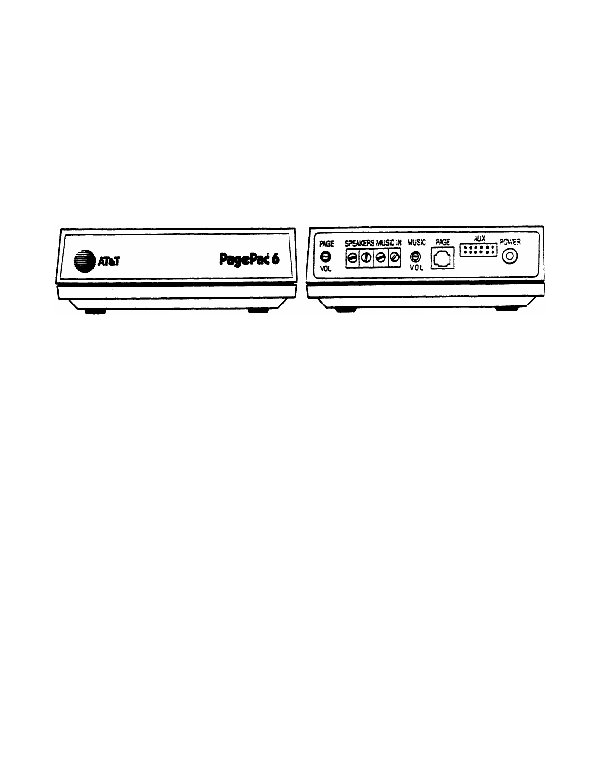
Front
Rear
PagePac® 6 Voice Paging System
FEATURES
●
Connects to your telephone system through standard modular telephone cords.
●
Uses standard touch-tone or rotary telephones to page.
●
Provides a 6-watt, voice-coil output.
●
Supports a wide range of indoor and horn speakers.
●
Controls background music provided from a separate source, such as the PagePac MusicMate™, an FM tuner, a tape deck, or leased source, etc.
NOTE: Those who use paging systems to rebroadcast copyrighted music are required to obtain
licenses from and pay fees to copyright owners. This usually involves obtaining licenses and
paying fees to either ASCAP and/or BMI (American Society of Composers, Artists and
Producers, Broadcast Music Inc.). It is the user’s obligation to obtain any license required
and pay any fees.
●
Comes with its own 12-VAC power supply that plugs into any standard 120-VAC, 60 Hz outlet.
●
Connects directly to your telephone system page port.*
●
Offers separately purchased adapters for telephone systems without page port connections.
*Page port must provide a dry contact closure.
1
Page 4
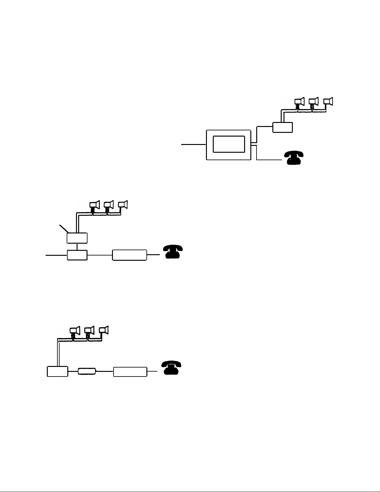
There are several ways to connect PagePac 6
to your AT&T telephone system.
●
For telephone systems equipped with a
page port that has either a modular jack
or screw-type connections, PagePac 6
connects directly to the page port.
PagePac 6
Incoming
Central Office
Lines*
PagePac 6
Port Saver
Speakers
Line Jack
Telephone
System
INSTALLATION
PagePort
Incoming
Central Office
Lines*
Telephones
Telephone System
For telephone systems not equipped with a
page port, a choice of adapters is available:
●
Jack
C.O. Line Protector Model 146
The
PagePac 6 Port Saver
to the telephone system on an incoming
Central Office line jack and provides
paging while preserving normal telephone
service on that line.
Speakers
PagePac 6
Telephones
(Optional)
that connects
C.O. Line Protector Model 146
(Optional)
Speakers
●
A
PagePac Trunk Adapter
that connects
PagePac 6 to the telephone system on an
incoming Central Office line jack.
Line Jack
PagePac 6
*If using a C.O. Line Protector that provides both telephone and AC power connections, such as the Model 146,
connect both the PagePac 6 modular cord and power cord to the protector.
Trunk
Adapter
Telephone
System
Telephones
NOTE:
This connection option dedicates
that line for Page-only service.
2
Page 5
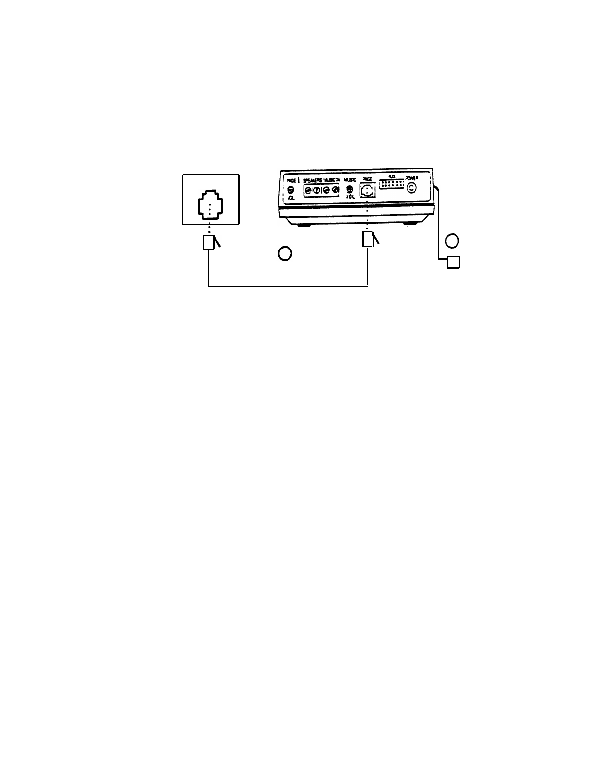
CONNECTING PAGEPAC 6 TO A PAGE PORT
Telephone System
Page Jack
1
Modular Line Cord
PagePac 6
2
ll
To 120 VAC, 60 Hz
Connections to a Page Jack
(Circled numbers correspond to the steps in the installation procedure below.)
Required Materials
PagePac 6
—
Standard modular telephone cord of sufficient length to connect the PagePac 6 to the telephone
—
system page jack.
Installation Procedure
PagePac 6 can be placed on a desk or shelf, or wall-mounted using the keyhole slots in the bottom
of the unit. After selecting a convenient location:
Connect the PAGE jack on the PagePac 6 to the telephone system page jack with a modular cord.
1.
Plug the PagePac 6 power cord into a standard AC wall outlet, or use an extension cord if necessary.
2.
Note:
If the page port has screw-type connections, use a half-modular cord to connect to the page
port. The modular end of the cord connects to the PagePac 6 PAGE jack. On the other end of the
cord, the red lead connects to page ring, and the green lead to page tip. The black and yellow leads
are control leads that connect to a dry contract closure provided by the page port.
3
Page 6
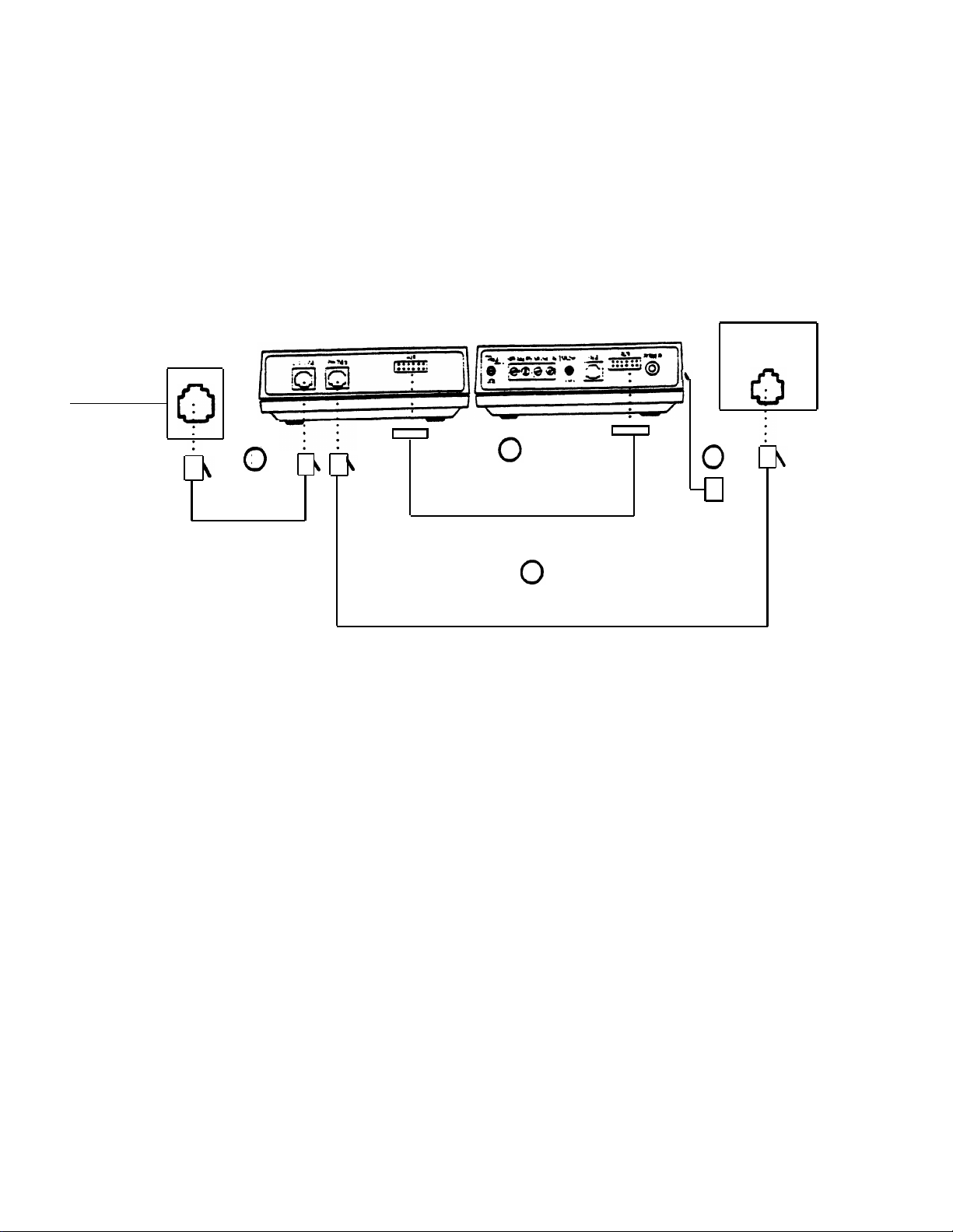
CONNECTING PAGEPAC 6
USING THE PAGEPAC 6 PORT SAVER
Incoming
Telephone
Lines*
Modular Jack
(725A-Type)
Modular
3
Cord
PagePac 6
Port Saver
Cable Supplied With
PagePac 6 Port Saver
Modular Cord
PagePac 6
1
2
Connections to a Line Jack Using the PagePac Port Saver
(Circled numbers correspond to the steps in the installation procedure.)
Telephone System
Incoming
Line Jack
4
ll
To 120 VAC
60 Hz
Required Materials
PagePac 6
—
PagePac 6 Port Saver
—
Two standard modular cords of sufficient length to make the connections shown in the figure above.
—
*If using a C.O. Line Protector that provides both telephone and AC power connections, such as the Model 146,
connect both the PagePac 6 modular cord and power cord to the protector.
4
Page 7
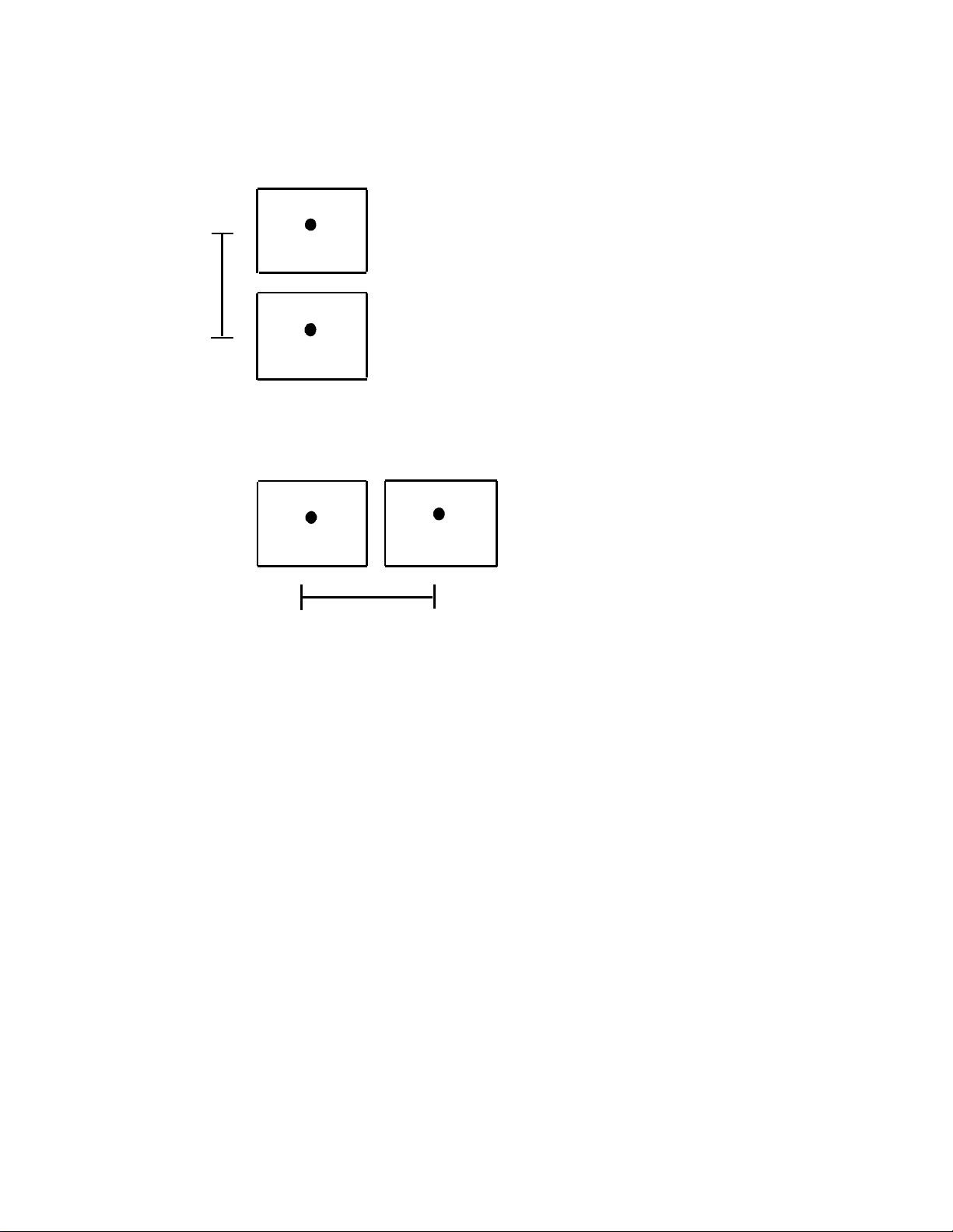
5 in.
Port Saver
Port Saver may be mounted above PagePac 6.
Distance between keyhole slot centers is 5 in.
PagePac 6
Port Saver
PagePac 6
PagePac 6. Distance between keyhole slot
centers is 6.5 in.
Port Saver may be mounted to the side of the
NOTE:
Spacing shown is only a suggestion.
Circumstances may require different spacing.
6.5 in.
Wall Mounting Arrangements for Port Saver & PagePac 6
Installation Procedure
PagePac 6 and PagePac 6 Port Saver may be placed on a desk or shelf, or may be wall mounted
(see illustrations above) using the keyhole slots in the bottom of the unit. The units must be
within six to eight inches of each other (see step 1 below).
1.
Connect the AUX jack on the PagePac 6 to the PagePac 6 Port Saver via the Port Saver
ribbon cable (the AUX jack is keyed, therefore, you can connect the cable in only one way).
Connect the PHONE jack on the PagePac 6 Port Saver to a telephone system line jack
2.
(the line that goes to the telephone), using a modular cord.
Connect the C.O. LINE jack on the PagePac 6 Port Saver to the modular jack where the
3.
telephone line from the telephone company appears, using a modular cord.
4.
Plug the PagePac 6 power cord into a standard AC wall outlet, or use an extension cord
if necessary.
5
Page 8
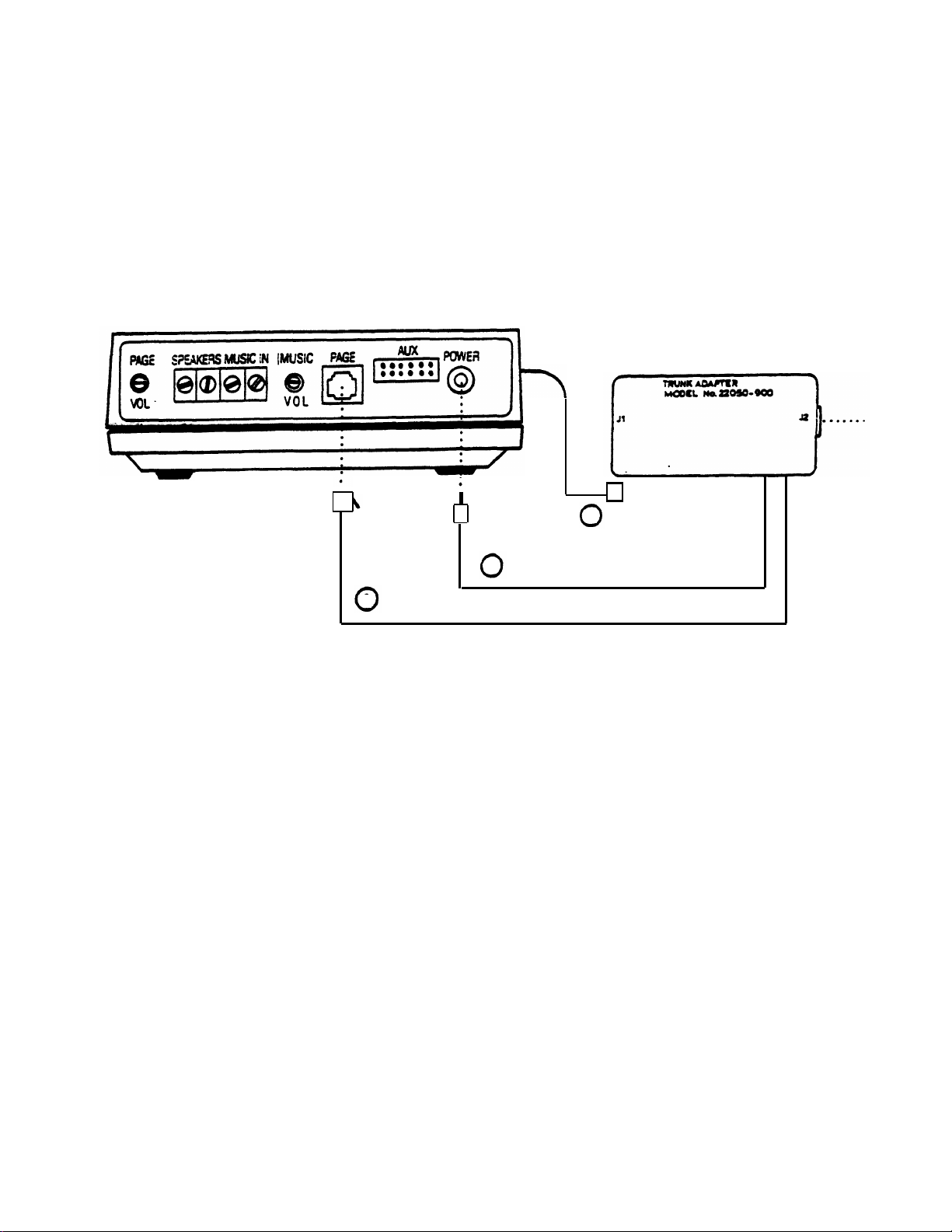
CONNECTING PAGEPAC 6
USING A PAGEPAC TRUNK ADAPTER
PagePac 6
Trunk Adapter
ll
4
2
1
Connections to a Line Jack Using the PagePac Trunk Adapter
(Circled numbers correspond to the steps in the installation procedure.)
Required Material
PagePac 6
—
PagePac Trunk Adapter
—
—
Standard modular telephone cord of sufficient length to connect the Trunk Adapter to the telephone
system line jack.
6
Page 9

Telephone System
Incoming
Line Jack
3
Installation Procedure
PagePac 6 can be placed on a desk or shelf, or wall-mounted using the keyhole slots in the bottom
of the unit. After selecting a convenient location:
Connect the Trunk Adapter modular cord to the PagePac 6 PAGE jack.
1.
2.
Connect the Trunk Adapter power cord to the PagePac 6 POWER OUT jack.
Connect the Trunk Adapter jack J2 to the telephone system page jack with a standard modular cord.
3.
4.
Plug the PagePac 6 power cord into a standard AC wall outlet, or use an extension cord if necessary.
7
Page 10

CONNECTING SPEAKERS TO PAGEPAC 6
Both standard speakers (indoor cone-type) and horn speakers may be used with PagePac 6.
For best performance, use only the type speaker recommended for your situation (see below),
and do not exceed the number of speakers or speaker run length maximums shown below.
Recommended Speakers
PAGING AREA
Open or Closed
Office Areas
Conference
Room Etc.
Hallways
Private Office
Open Industrial
Area or Outdoors
Total Speakers
Speakers Per Run*
Max. Length of
Speaker Run
(24 AWG Wire)
MOUNTING LOCATION
On Wall or Ceiling
Above the Ceiling
On Wall or Ceiling
Placed on Desk or Wall
On Wall or Pole at Least
15 Ft. Above Ground
Speaker Limitations
STANDARD INDOOR SPEAKERS HORN SPEAKERS
24
5
100 Ft.
SPEAKER TYPE
Universal Cabinet
Recessed Ceiling
Universal Cabinet
Desktop or Wall
Horn
AT&T ORDER NO.
PEC 53511
COMCODE 403307770
PEC 53514
COMCODE 403307796
PEC 53511
COMCODE 403307770
PEC 53516
COMCODE 403307804
PEC 53512
COMCODE 403307788
6
1
100 Ft.
*A run is a line of one or more speakers that connects directly to PagePag 6. If using both
horns and standard speakers, each horn counts as four standard speakers.
In some situations you may be able to extend a run farther than 100 feet, by using fewer
speakers and/or larger wire.
8
Page 11

Third Run
Speakers
Second Run
Speakers
First Run
Speakers
22050-910
(Optional)
Output
Cord
Y-Connector Supplied
with adapter
Figure B
Speaker connections to PagePac 6
Required Materials
—
PagePac loudspeakers recommended for use with PagePac 6
—
24 AWG speaker wire
Standard installation tools—screwdriver, wire cutters/strippers, pliers, hammer, etc.
—
(Optional) Speaker adapter model 22050-910.
—
Figure A
ll
Installation Procedure
1. Install the speakers according to the directions supplied with them.
Connect the speaker run to the SPKRS terminals on PagePac 6 (Figure A).
2.
3.
(Optional) Use speaker adapter for more than one speaker run, as shown in Figure B.
9
Page 12
2
MusicMate™
Output Cord
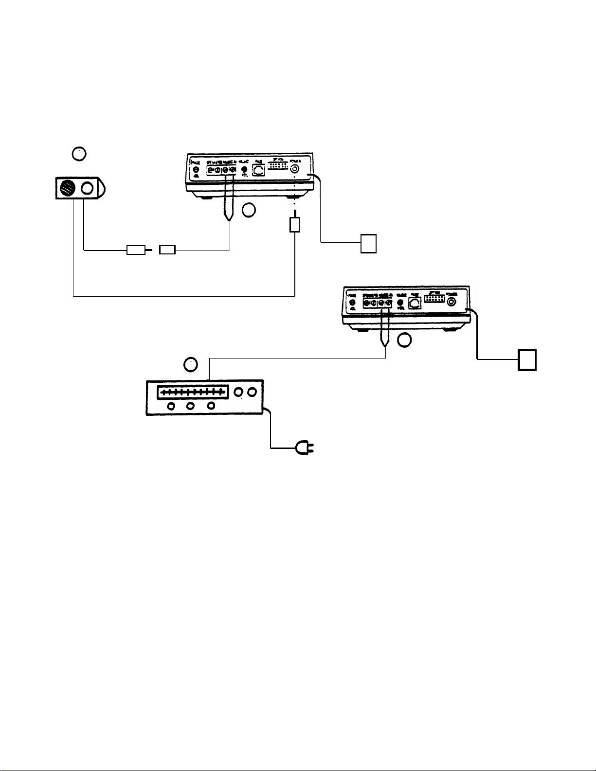
CONNECTING A MUSIC SOURCE* TO PAGEPAC 6
Figure A
1
Y-Connector
(Supplied)
DC Power Cord
Connections Using MusicMate™
Wiring Supplied By Installer
2
Signal From
Music Source
ll
Figure B
1
ll
Music Source
(FM Tuner, etc.)
Connection Using An Alternate Music Source
Music Source Connections to PagePac 6
Required Materials
PagePac MusicMate™ or alternate source, such as FM tuner, tape deck, leased source, etc.
—
(If an alternate source is used) Wire for making connection between music source and PagePac 6.
—
Speaker wire (24 AWG) may be used for this purpose.
10
Page 13

Installation Procedure
Connect MusicMate (Figure A), or alternate source (Figure B), to the PagePac 6 MUSIC IN
1.
terminals.
When using MusicMate (Figure A), connect the MusicMate D.C. power cord to the PagePac
6 POWER jack. A phono-jack-to-screw-terminals adapter is provided with the MusicMate. Use
it to connect the MusicMate output cord to the PagePac 6 MUSIC IN terminals.
Turn on the music source (the output should be heard over the paging speakers).
2.
Select a station and set the volume control, as follows:
3.
If using MusicMate, follow the instructions supplied with the unit. Then use the MUSIC VOL
—
control on the PagePac 6 to adjust the volume, as described in the OPERATION Section of
this manual, Page 18.
Set the volume control at mid-range and then use the MUSIC VOL control on the PagePac
—
6 to adjust the volume, as described in the OPERATION Section of this manual. Page 18.
NOTE:
If, during a page or when using talkback, you hear music in the speakers or phone, reverse
the position of the wires on the MUSIC IN terminals.
NOTE: Those who use paging systems to rebroadcast copyrighted music are required to obtain
licenses from and pay fees to copyright owners. This usually involves obtaining licenses and
paying fees to either ASCAP and/or BMI (American Society of Composers, Artists and
Producers, Broadcast Music Inc.). It is the user’s obligation to obtain any license required
and pay any fees.
11
Page 14

OPERATION
Paging procedures differ slightly depending on the requirements of your telephone system and
how it is connected to PagePac 6. If your system is connected using a PagePac 6 Port Saver,
pay particular attention to the pertinent instruction section below.
PAGING WHEN CONNECTED THROUGH A PAGE PORT OR A PAGEPAC TRUNK ADAPTER
The exact procedure for paging on your particular telephone system is explained in the user’s
manual that accompanies the telephone system. In general, though, the steps are as follows:
Access the paging function as required by your telephone system. If PagePac 6 is connected
1.
through a page port, you will probably push a button or dial or code to access the function. If PagePac 6 is connected through a PagePac Trunk Adapter, you win follow your
telephone system’s requirements for accessing the line reserved for paging.
Make the page.
2.
Replace the telephone handset gently (remember you are still connected to the loudspeaker).
3.
This will prevent loud noises from being heard over the paging system.
PAGING AND USING THE LINE WHEN CONNECTED THROUGH A PAGEPAC 6 PORT SAVER
The PagePac 6 Port Saver adds paging to one of your telephone lines, and allows you to continue to use that line for placing and receiving calls. The way you use the paging line differs
slightly from the way you use your other telephone lines. On the paging line you will hear
two distinctive tones:
●
Special Dial Tone—a distinctive tone that serves the same purpose as the regular dial tone.
It is the first tone you hear upon lifting the handset.
●
Call Waiting Tone—a standard ringing tone. You hear it when a call comes in while you
are paging. It is also heard through the paging speakers.
Paging
Lift the handset and listen for the distinctive dial tone.
1.
Dial 7. (If for some reason 7 cannot be used for page access, dialing 1, 5, or 6 will also
2.
access paging.)
Make the page.
3.
Replace the handset gently to prevent a loud noise from being heard over the paging system.
4.
Answering Calls While Paging
If a call comes in while you are off-hook preparing to page, but have not yet dialed “7”, the
caller is connected directly to your phone, with no ring.
If a call comes in while you are paging, you will hear Call-Waiting Tone (a ringing signal also
heard in the paging speakers). To answer the call, hang up and wait for your phone to ring.
The call may also be answered from any other phone that can answer that line.
12
Page 15

Placing a Call
Lift the handset and listen for the distinctive dial tone.1.
Dial 9 and listen for the regular dial tone. (Or, you may wait for the regular dial tone; this
2.
will take approximately 4 seconds.)
Dial the number you want to call.
3.
NOTE:
To dial emergency 911, dial 9 or
wait
for the regular dial tone, and then dial 911.
Using Last Number Redial
If your telephone has last number redial, you can use it with PagePac 6. The exact procedure
depends on whether or not your phone has a PAUSE button.
Redial Without a PAUSE Button
To place the initial call:
1.
Lift the handset and wait for the regular dial tone, approximately 4 seconds.
Dial the number you want to call.
2.
To Redial:
Lift the receiver and wait for the regular dial tone, approximately 4 seconds.
1.
Press the REDIAL button on the telephone.
2.
Redial With a PAUSE Button
To place initial call:
Lift the handset and listen for PagePac 6 dial tone.
1.
Dial 9.
2.
3.
Press the PAUSE button on the telephone.
Dial the number you want to call.
4.
To Redial:
Lift the handset and listen for PagePac 6 dial tone.
5.
Press the REDIAL button within 4 seconds.
6.
Note:
If you have problems using the PAUSE button, try the “Without a PAUSE Button”
procedure.
13
Page 16

ADJUSTNG PAGE AND MUSIC VOLUME
Volume controls on the rear of PagePac 6 allow you to adjust the volume of paging and background
music independently.
If your paging system fails to operate properly, follow the suggestions in the trouble analysis chart
before calling for professional assistance.
To adjust background music volume, turn the MUSIC VOL control clockwise to increase or
counterclockwise to decrease volume. If you do not use background music, turn the MUSIC VOL
control fully counterclockwise.
TROUBLESHOOTING PROCEDURES
The PagePac 6 contains no user-serviceable parts, and should be repaired only by authorized personnel. There are several types of installation and maintenance plans available from AT&T or your
dealer. For information or warranty service, call your AT&T sales representative or authorized dealer.
To adjust paging volume, turn the PAGE VOL control clockwise to increase or counterclockwise
to decrease volume.
Equipment Required
—
Harris Dracon Trunk Adapter PEC 53518
Standard installation tools—screwdriver, wire cutters/strippers, pliers, hammer, etc.
—
14
Page 17

Trouble Analysis Table
PROBLEM
No sound from one or more speakers
while others work.
Paging and music do not work. Or,
music works but paging does not.
CORRECTIVE ACTION
Check volume control on speaker.
Check all connections to speaker.
Replace bad speaker with good one. If speaker
cannot be replaced immediately, wire around it
to ensure service to the remaining speakers.
Ensure that the power supply is plugged in and
that the outlet has power.
Check the volume controls on the rear of
PagePac 6.
Check speaker connections.
Isolate the source of the problem:
A.
If Connected to Page Port
Disconnect PagePac 6 from the Page Jack.
1.
Connect the Trunk Adapter to the PagePac 6
2.
as shown on Page 10.
Connect a 2500-type telephone to the Trunk
3.
Adapter jack J2.
4.
If the PagePac 6 is working, you will be able
to page using the telephone. Music should
also work, and be switched out during a page.
B.
If Connected Using A Trunk Adapter
Disconnect the Trunk Adapter from the line jack.
1.
2.
Connect a 2500-Type telephone to the Trunk
Adapter jack J2.
3.
If the PagePac 6 is working, you will be able
to page using the telephone. Music should
also work, and be switched out during a page.
15
Page 18

Trouble Analysis Table (continued)
PROBLEM
Paging and music do not work. Or,
music works but paging does not
(continued).
Paging and music are garbled.
CORRECTIVE ACTION
If Connected Using PagePac 6 Port Saver
C.
Disconnect the PagePac 6 Port Saver from the
1.
telephone line jack.
Connect a standard telephone to the PHONE
2.
jack on the PagePac 6 Port Saver.
3.
If PagePac 6 is working, you will be able to
page using the telephone. Music should also
work, and switch out during a page. You
should also be able to access the telephone
line if it is connected.
If system does not function as it should, you
4.
may disconnect the PagePac Port Saver from
the PagePac 6 and use steps 2, 3 and 4 of
procedure A (above) to check the operation
of the PagePac 6.
Check speaker wire for shorts. Look for staples
driven through wire. Check all connections.
Paging works, but music does not.
Ensure music source has power.
Adjust PagePac 6 MUSIC VOL control.
Adjust volume control on music source.
Tune music source to strong station.
Check all connections.
Replace music source.
16
Page 19

If, for any reason, you need to know the pinouts for the modular jacks on the PagePac 6 or PagePac 6
Port Saver, pinout information is given below.
PagePac 6 PAGE Jack
Pin* Cord Lead†
1
Not Used
2
Black
3
Red Ring
4
Green
5
Yellow
6
Not Used
Function
Not Used
Access Control (C)
Tip
Access Control (C1)
Not Used
Not Used
Dry Contact Closure (C)
Ring
Tip
Dry Contact Closure (C1)
Not Used
Connect to Paging Port
*Pins numbered from left to right, as seen when looking into jack.
†When using a standard modular cord.
Note:
A telephone system paging port dry contact closure is required to connect pins 2 and 5 of
the PAGE jack together to access paging.
PagePac 6 Port Saver C.O. LINE and PHONES Jacks
Pin*
1
2
3
4
Cord Lead†
Not Used
Not Used
Red
Green
Function
Not Used
Not Used
Ring
Tip
Not Used
Not Used
Ring
Tip
Connect to Line Jack
5
6
Not Used
Not Used
Not Used
Not Used
Not Used
Not Used
*Pins numered from left to right, as seen when looking into jack.
†When using a standard modular cord.
17
Page 20

WARRANTY INFORMATION
LIMITED WARRANTY AND LIMITATION OF LIABILITY
AT&T warrants to you that the product will be free from defects in material and workmanship
when title passes to you. If you notify AT&T that the product has failed to operate as warranted
within one year of the date title passes to you, AT&T will, at its option, repair or replace the component or components of the product that failed to operate as warranted. Any repair or replacement components may be new or refurbished and will provided on an exchange basis. If AT&T
determines that the product cannot be repaired or replaced, AT&T will refund the purchase price
to you.
If you purchased the product directly from AT&T, AT&T will perform warranty repair on your
premises in accordance with the terms and conditions of AT&T’s “Business Day” or “Aroundthe-Clock” warranty plans. The details of AT&T’s warranty plans may be obtained from AT&T.
If you purchased the product from an authorized dealer, you will be covered by AT&T’s authorized
dealer warranty plan during the warranty period. Contact your authorized dealer for details of
AT&T’s authorized dealer warranty plan.
above is your exclusive remedy.
The limited warranties provided above do not cover damages, defects, malfunctions or product
failures caused by:
●
Failure to follow AT&T’s installation, operation or maintenance instructions;
●
Unauthorized modification or alteration of the product or its components;
●
Product abuse, misuse or the negligent acts of persons not under the reasonable control of AT&T;
●
Actions of third parties and acts of God other than power surges (e.g., lightning).
AT&T’s obligation to repair, replace or refund as set forth
This limited warranty applies only to the product purchased directly from AT&T or purchased directly
from an authorized AT&T dealer. This limited warranty does not apply to products purchased or
operated outside the United States.
You may be required to provide AT&T with proof of purchase before AT&T will perform any warranty repair or provide any warranty replacements.
EXCEPT AS SPECIFICALLY SET FORTH ABOVE, AT&T, ITS AFFILIATES, SUPPLIERS AND
DEALERS MAKE NO WARRANTIES, EXPRESS OR IMPLIED, AND SPECIFICALLY
DISCLAIM ANY WARRANTY OF MERCHANTABILITY OR FITNESS FOR A PARTICULAR
PURPOSE.
EXCEPT FOR PERSONAL INJURY, THE LIABILITY OF AT&T, ITS AFFILIATES, SUPPLIERS AND DEALERS FOR ANY CLAIM, LOSS, DAMAGE OR EXPENSE FROM ANY
CAUSE WHATSOEVER, REGARDLESS OF THE FORM OF THE ACTION, WHETHER IN
CONTRACT, TORT OR OTHERWISE, SHALL NOT EXCEED THE LESSER OF DIRECT
DAMAGES PROVEN OR THE REPAIR OR REPLACEMENT COST OF THE SYSTEM OR
THE SYSTEM’S PURCHASE PRICE. IN NO EVENT SHALL AT&T, ITS AFFILIATES, SUPPLIERS AND DEALERS BE LIABLE FOR INCIDENTAL, RELIANCE, CONSEQUENTIAL
OR ANY OTHER INDIRECT LOSS OR DAMAGE (INCLUDING LOST PROFITS OR
REVENUES SUSTAINED OR INCURRED IN CONNECTION WITH THE SYSTEM). THIS
LIMITATION OF LIABILITY SHALL SURVIVE FAILURE OF THE EXCLUSIVE REMEDY
SET FORTH IN THE LIMITED WARRANTY ABOVE.
18
Page 21

FCC REGULATIONS PERTAINING TO THIS EQUIPMENT
FCC (PART 15)
Radio Frequency Interference
The PagePac 6 generates and uses radio frequency energy and if not installed and used in strict
accordance with the manufacturer’s instructions, may cause interference to radio and television
reception. Testing has been conducted for compliance with the limits for Class B device in accordance with the specifications in Subpart J of Part 15 of the FCC Rules. This testing is designed
to provide reasonable protection against such interference. However, there is no guarantee that interference will not occur in a particular installation. If this equipment does cause interference to
radio or television reception, which can be determined by turning the PowerMate unit off and on,
the user is encouraged to try to correct the interference by one or more of the following measures:
●
Reorient the radio or TV receiving antenna
●
Relocate the PagePac 6 with respect to the radio or TV receiver or vice-versa.
●
Plug the PagePac 6 into a different outlet so that it and the radio or TV reciever are on different
branch circuits.
If necessary, the user should consult the dealer or an experienced radio/television technician for
additional suggestions. The user may find the following booklet, “How To Identify and Resolve
Radio-TV Interference Problems,” helpful. This booklet was prepared by the Federal Government
Printing Office, Washington, DC 20402. Stock order No. 004-000-00345-4.
FCC (PART 68)
This equipment is registered with the Federal Communications Commission (FCC) in accordance
with Part 68 of its Rules. The FCC requires that the manufacturer provide you with the following
information:
1.
Connection and Use with Nationwide Telphone Network
The FCC requires that you connect your telephone equipment to the nationwide telephone network through a modular telephone outlet or jack. The modular telephone outlet or jack to which
the equipment must be connected is a USOC RJ11C.
Registered equipment may not be used with Coin Telephone Lines. Equipment may be used with
Party Lines in areas where state tarifs permit such connections and when equipment is adaptable
for such use.
2.
Information You May Need to Supply the Telephone Company.
Upon request of your local telephone company, you are required to provide them with the following
information:
The lines to which you will connect the telephone equipment.
A.
B.
The FCC registration number and ringer equivalence number (REN). Both numbers are listed
on the equipment label. The REN is useful to determine how many devices you may connect to
your telephone line and still have them ring when your telephone line is called. In most, but not
all, areas, the sum of all RENs per line should be 5 or less. You may want to contact your local
telephone company. The local telephone company must also be notified upon final disconnection
of the equipment from the local telephone company lines.
19
Page 22

©
Copyright 1988 AT&T
All rights reserved Printed in U.S.A.
999-500-246
Issue 1, Dec. 1988
 Loading...