

Page 1
Specifications subject to change without notice
© 2001 Atlas Sound LP Printed in U.S.A. 000501 SL11-1502
479
ELEVEN
1601 JACK MCKAY BLVD. / ENNIS, TEXAS 75119 U.S.A. / TELEPHONE: (800) 876-3333 / FAX (800) 765-3435
TUBE STAND BOOM BOOM
TRIANGULAR
STABILITY BASE TUBE
MODEL STYLE HEIGHT LENGTH
COUNTERWEIGHT
BASE FACTOR** FINISH FINISH WEIGHT
SB-36W 49" - 73" 62" Adjustable, 1890
I.S.I.
Ebony with a Chrome 40 lbs
Two-
(1245 x 1854mm)
(1575mm) 6 lbs (2.75 kg) 21"* Chrome Shell (18 kg)
SB-11WE Section 43" - 68" 60" Adjustable (533mm) 1610
I.S.I.
Ebony Ebony 26 lbs
(1219 x 1829mm)
(1524mm) 2 lbs (.9 kg) (11.8 kg)
FEATURES
• Professional Boom Stand for Stage and Studio Use
• Caster-Equipped Model Offers Silent and Effortless Mobility
• Adjustable 6 or 2-lb. Counterweight Provides Precision, Balance, and Stability
• Wearproof, Three-Piece Clutch Offers Secure, Fast, and Noise-Free Adjustment
• Variable, Piston-Type Air Suspension System on SB-36W Model Ensures
Microphone Protection
• Rugged Construction and Heavy-Duty Components Assure Long Service Life
• Made in U.S.A. to High Quality Standards
APPLICATIONS
This Atlas Sound®brand professional quality boom stands incorporate the functional features
and service reliability desired by performers and musicians, as well as broadcast/recording studios, theaters, and performance centers. All models are designed to meet the varying operational requirements of daily recording applications by combining maximum height and boom articulation ranges with increased mobility and dependable performance.
GENERAL DESCRIPTION
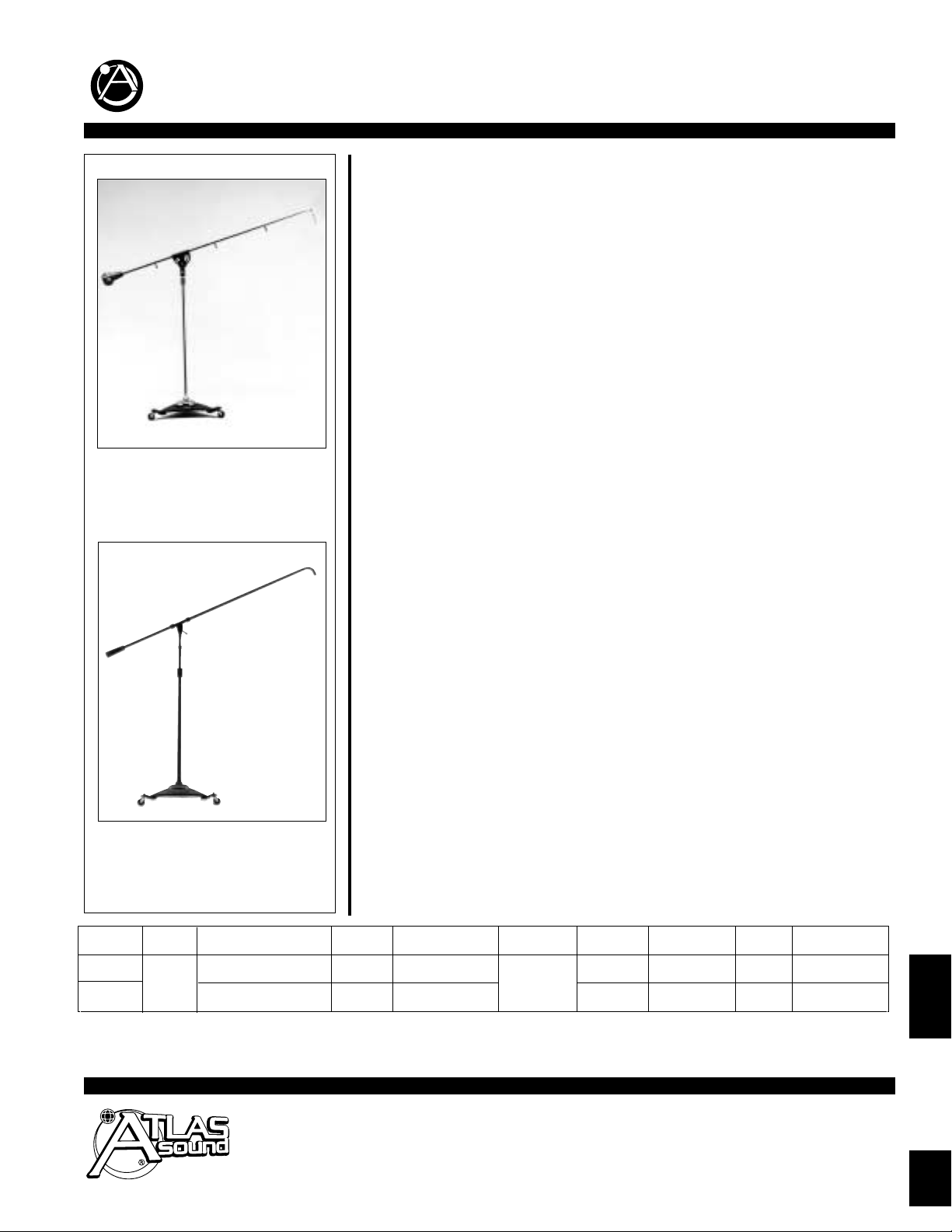
SB-36W.These top-of-the-line boom stands feature a variable, piston-type air suspension sys-
tem to ensure microphone protection. Model SB-36W is equipped with silent-motion, ball-bearing swivel casters of hard rubber for friction-free and vibration-absorbing mobility.
Two-piece horizontal boom assembly is
7
⁄8" dia. cold rolled steel with a heavy-duty, die-cast,
gyromatic swivel and an adjustable 6-lb. counterweight for precise and secure orientation.
Tubing terminates with an adjustable mic holder swivel with standard
5
⁄8
" - 27 thread to accept
all microphones, holders, and adapters. Guide clips are supplied for cable attachment.
Vertical tube assembly is manufactured of 1
1
⁄8" and 7⁄8" chrome-plated cold rolled steel and
includes the wearproof Atlas Sound
®
grip-action clutch for easy adjustment and positive locking.
Model SB-36W includes wheels for a height span of 49" to 73". Triangular cast metal base with
edge-concentrated weight distribution offers extra stability and is finished in ebony epoxy with a
chrome shell.
SB-11WE. Economical studio boom is especially suited for small studio/broadcast applications
and for stage miking of drums and percussion instruments. Unit features a 60" long, two-piece
horizontal boom assembly constructed of steel tubing. Boom includes a Performer Series swivel clamp and an adjustable 2-lb. counterweight for effortless boom arm orientation. Tubing also
incorporates a 90° angled end for optimum microphone positioning and terminates in the standard
5
⁄8" - 27 thread to accept all microphones, holders, and adapters.
Vertical tube assembly is 11⁄8" and 7⁄8" dia. cold rolled steel with an adjustable height span of 43"
to 68". Tubing features the wearproof Atlas Sound
®
grip-action clutch for positive locking control. Triangular die-cast base with edge-concentrated weight distribution offers extra stability
and is equipped with three, hard rubber swivel casters for effortless and silent mobility. Entire
assembly is finished in non-reflective ebony epoxy.
* Dimension includes wheels. Triangular cast base is 15"
** Stability Index Factor (I.S.I.). Evaluates the ability of a stand/boom assembly to remain at rest when acted upon by an outside force. (For explanation, refer to SL11-1501.)
SB-36W
SB-11WE
STUDIO BOOM STANDS
SB-36W
SB-11WE
Page 2
Specifications subject to change without notice
© 2001 Atlas Sound LP Printed in U.S.A. 000501 SL11-1502
1601 JACK MCKAY BLVD. / ENNIS, TEXAS 75119 U.S.A. / TELEPHONE: (800) 876-3333 / FAX (800) 765-3435
1.
3.
2.
4.
5.
6.
2.
4.
3.
5.
8.
7.
9.
11.
12.
13.
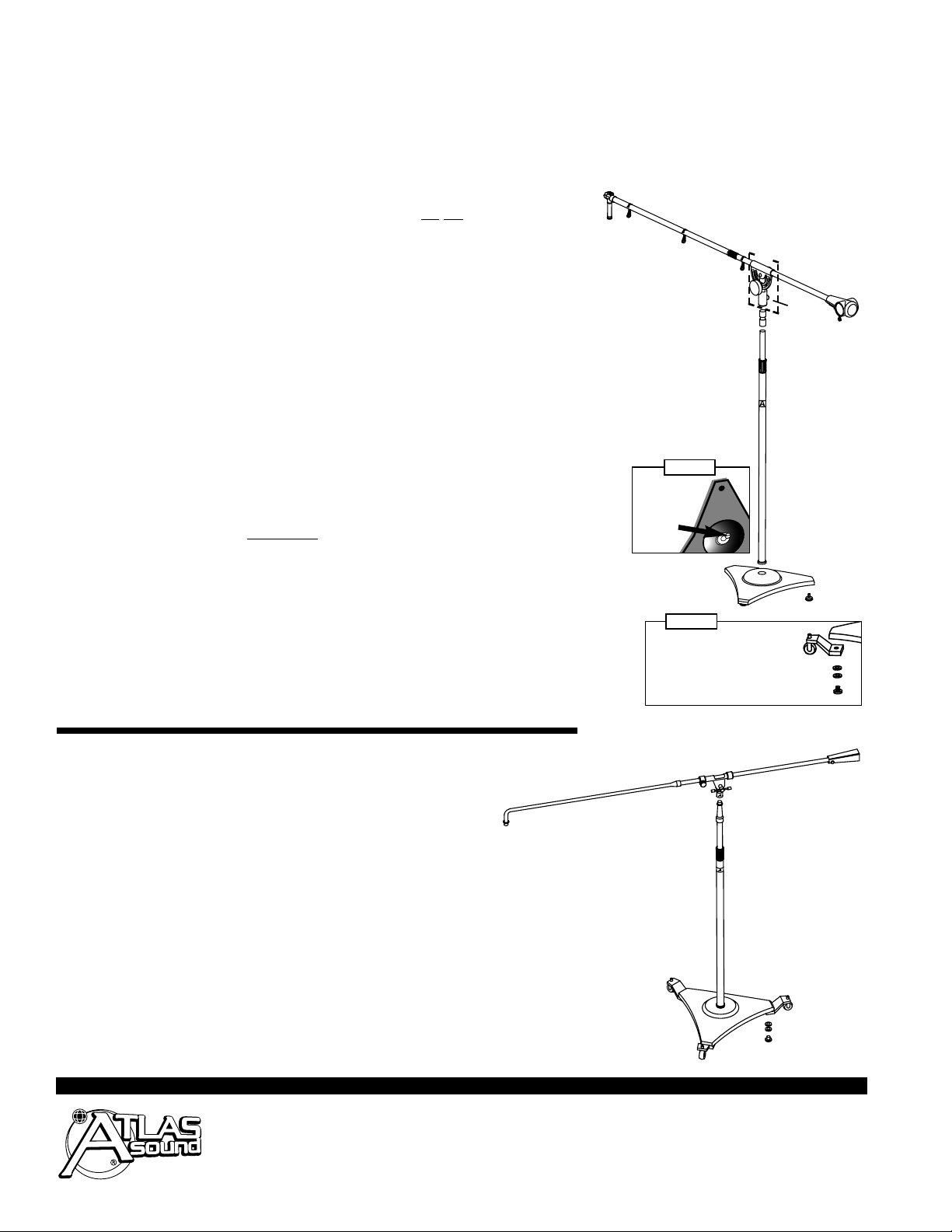
Underneath
Base
Air CheckValve
Screw
SB-36W
& SB-11WE
Caster
Assembly
Fig. #1
ATLAS SOUND®STUDIO BOOM STAND ASSEMBLY INSTRUCTIONS
10.
6.
Fig. #2
Flat Washer
Lock Washer
Bolt
SB-36W ASSEMBLY INSTRUCTIONS
A. Remove the chrome plated decorative shell #1 from the underside of the
base casting #2. Discard the rubber "O" shipping ring. Do
not adjust the
check valve screw on the base until the upright tube is securely in position
(see Fig. #1). Place the chrome shell into position on top of the base.
B. Thread the upright tube assembly #3 securely into the base to avoid air
leakage. Faulty operation of the air check-valve device on the underside of
the base will be noticed if the upright tube is not installed tightly.
C. Now the air check-valve screw, located on the underside of base, may be loos
ened or tightened for desired cushioning of the microphone stand tube assembly
(see Fig. #1).
D. On Model SB-36W, attach three swivel casters onto the base using the lock
washers, flat washers, and bolts provided (see Fig. #2).
E. Thread swivel adapter #5 on top of the installed upright
7
⁄8
" tube assembly.
Next, install the swivel assembly
#6 on top of the adapter. Tighten swivel
assembly screw #7.
F. Install counterweight #8 on unthreaded end of
7
⁄8" boom tube #9, then insert
threaded end through swivel assembly and attach coupler #10.
G. Thread remaining boom tube #11 into the coupler. Next, thread the
hang-straight swivel #12 onto the end of the boom assembly.
H. Tighten all hardware and tubes securely. Attach the three cable hangers, #13,
onto the boom for microphone cable management.
I. Attach desired microphone to the threaded hang-straight swivel on the
end of the boom.
SB-11WE ASSEMBLY INSTRUCTIONS
A. Attach the three swivel casters onto the base using the lock
washers, flat washers, and bolts provided (see Fig. #2 above).
B. Thread upright tube assembly #3 securely into base #2. Use care to thread the
tube perpendicular to the base to avoid stripping the threads.
C. Thread swivel assembly #4 onto the top of the upright tube assembly.
D. Place the straight boom tube #5, that contains the counterweight, through the
swivel assembly. Next, thread the straight boom tube into the flared female end
of the remaining boom tube #6.
E. Tighten all hardware and tubes securely.
F. Attach desired microphone to threaded, angled end of the boom.
 Loading...