

Page 1

1/8
IP-PM8GD
IP Enabled Pendent Mount Speaker
Safety Instructions
Please read carefully before installing or operating.
• Read all instructions carefully
• Heed all warnings
• Assure that the speaker is securely mounted
• Always assure amplifier power is off before making any connections
• Keep instructions for future reference
• Should any questions arise after reading this document, please call Atlas Sound Tech Support at 800-876-3333
Hearing Damage
CAUTION: All professional speaker systems are capable of generating very high sound pressure levels. Use care with placement and operation to
avoid exposure to excessive levels that can cause permanent hearing damage.
ATTENTION: Tous les systèmes de haut-parleurs professionnels sont capables de générer des niveaux de pression sonore très élevés. Utilisez les
soins avec le placement et l'opération pour éviter l'exposition à des niveaux excessifs pouvant causer des dommages auditifs permanents.
Suspension and Mounting
Suspending or "flying" speaker systems requires training and expertise. Improper rigging of a flying speaker may result in injury, death, equipment
damage, and legal liability. Installation must be carried out by fully qualified installers, in accordance with all required safety codes and standards at the
place of installation.
A 5:1 design factor is a generally accepted minimum standard. However, legal requirements for overhead suspension vary by municipality, please
consult your local safety standards office before installing any product. We also recommend that you thoroughly check any laws and bylaws prior to
installation.
Speakers flown in theaters, nightclubs, conference centers, or other places of work and entertainment must be provided with an independent,
correctly rated and securely attached secondary safety — in addition to the principle suspension point(s). This secondary safety must prevent the
speaker from dropping more than (6") should the principle suspension device fail. If you lack the skills, training, and proper ancillary equipment to fly a
speaker system, do not attempt to do so.
Introduction
AtlasIED IP endpoint speakers consist of a factory assembled speaker and baffle with PCB amplifier / control board. The amplifier / control board is
capable of producing 15-watts RMS into the 8Ω loudspeaker with IEEE 802.3at compliant PoE switches. Interconnection is via a top panel mounted
female RJ-45 connector. All models are compatible with AtlasIED’s GCK©, Syn-Apps SA-Announce©, Singlewire’s InformaCast© software, and SIP
standalone operation.
Functionality
Before installing, note the unit’s MAC address found under the top cover (example 00:02:C1:81:00:00). Once connected to a network and powered,
the IP endpoint speaker will boot up and automatically obtain an IP address from a DHCP server on the network. Next, the unit will start the
registration process to find the controller software. Once the IP endpoint speaker identifies the software’s location, it will send a registration request
to the software and register. The MAC address of the unit will then be visible in the software’s interface. Please refer to the installation manual of the
software for additional configuration settings.
After the speaker has registered with the software, using any Internet browser like Internet Explorer, Safari, Firefox, Chrome, etc., will allow access
to the unit’s HTTPS page by navigating to its IP address. This page will show the unit’s current firmware version and registration information. If unsure
about the IP address, press the unit’s service button for one second and the unit’s IP address will be announced through the speaker. This will require
removal of the top panel of the enclosure to access PCB. Please contact AtlasIED for instructions to configure the IP-PM8GD in SIP Standalone Mode.
©2018 Atlas Sound L.P. The Atlas “Circle A”, Soundolier, and Atlas Sound are trademarks of Atlas Sound L.P. IED is a registered trademark of Innovative Electronic Designs LLC.
All Rights Reserved. All other trademarks are the property of their respective owners. All specs are subject to change without notice. ATS005842 RevA 9/18 PN 493536
1601 JACK MCKAY BLVD.
ENNIS, TEXAS 75119 U.S.A.
TELEPHONE: (800) 876-3333
FAX (800) 765-3435
AtlasIED.com
Page 2

2/8
Misc Settings
1. Service Button - The only push switch located on the main circuit board.
• Press 1 sec - The current IP address will be spoken (in English) through the 8Ω loudspeaker
• Press 10 sec - Factory reset
• Press and hold while applying power - Hold the button until the Status LED on the circuit board starts blinking rapidly to perform a factory
reset without any servers present
Note: To access PCB remove back top panel of the speaker enclosure.
Installation Via Mounting Cables (Included)
General considerations and hardware recommendations
CAUTION: A fall from almost any height could result in serious injury or death. Assure that the speaker is firmly mounted to an object that can handle
the weight of the IP-PM8GD. The mounting surface the IP-PM8GD is being attached to should be able to handle five or more times the weight of the
IP-PM8GD.
The hardware employed must be safely and securely attached both to the speaker and the structure in question, using only the mounting holes. A
general rule for soft surface installations (wood beams) is to multiply the corresponding working load limit by 75%: the result will be approximate
working load strength. Use thread locking compound for all installations.
CAUTION: Mounting the IP-PM8GD may require two people.
When in doubt contact a qualified structural/mechanical engineer for approval of the mounting materials and methods.
1. Rotate the top cover counterclockwise and pull up to remove. (Figure 1 and 2)
2. Locate suitable support structure in the area the speaker is to be installed.
3. Route the bare end of the main support cable though the included clamp, then around the mounting structure, and back through the clamp.
(Figure 3 and 4)
4. Adjust the cable length in the clamp so that the eyelet end of the cable is at the final height above the floor. (Figure 5)
5. Route the eyelet end of the main support cable through the top cover of the IP-PM8GD. Attach the included carabiner clip to the eyelet and the
large mounting hole on the back of the IP-PM8GD. (Figure 6)
6. Repeat steps 1 - 4 for the safety cable and attach it to one of the outer mounting holes on the support plate of the IP-PM8GD using the included
mounting screw. (Figure 6)
7. Route the Ethernet cable through the top cover and connect to the RJ-45 Connector.
8. Position the top cover over the side cover screws and rotate the cover clockwise to align the top cover mounting screw holes. Install the 3
mounting screws which are located in the hardware bag. Then tighten the side cover screws.
9. Slide the top hole plug over the main support cable, safety cable, and Ethernet cable using the opening on the side of the plug. Then slide the plug
down the cable and into the top cover hole. (Figure 7 and 8)
Note: If the speaker is being installed outdoors, seal plug with RTV silicone to prevent moisture from entering speaker.
©2018 Atlas Sound L.P. The Atlas “Circle A”, Soundolier, and Atlas Sound are trademarks of Atlas Sound L.P. IED is a registered trademark of Innovative Electronic Designs LLC.
All Rights Reserved. All other trademarks are the property of their respective owners. All specs are subject to change without notice. ATS005842 RevA 9/18 PN 493536
1601 JACK MCKAY BLVD.
ENNIS, TEXAS 75119 U.S.A.
TELEPHONE: (800) 876-3333
FAX (800) 765-3435
AtlasIED.com
Page 3
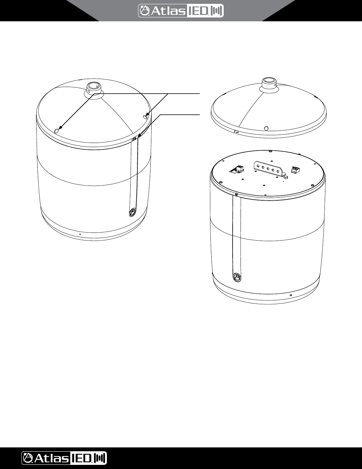
Top Cover
Mounting Screws (3)
Top Cover
Side Screws (2)
3/8
Figure 1
Figure 2
©2018 Atlas Sound L.P. The Atlas “Circle A”, Soundolier, and Atlas Sound are trademarks of Atlas Sound L.P. IED is a registered trademark of Innovative Electronic Designs LLC.
All Rights Reserved. All other trademarks are the property of their respective owners. All specs are subject to change without notice. ATS005842 RevA 9/18 PN 493536
1601 JACK MCKAY BLVD.
ENNIS, TEXAS 75119 U.S.A.
TELEPHONE: (800) 876-3333
FAX (800) 765-3435
AtlasIED.com
Page 4

Figure 3
4/8
©2018 Atlas Sound L.P. The Atlas “Circle A”, Soundolier, and Atlas Sound are trademarks of Atlas Sound L.P. IED is a registered trademark of Innovative Electronic Designs LLC.
All Rights Reserved. All other trademarks are the property of their respective owners. All specs are subject to change without notice. ATS005842 RevA 9/18 PN 493536
1601 JACK MCKAY BLVD.
ENNIS, TEXAS 75119 U.S.A.
TELEPHONE: (800) 876-3333
FAX (800) 765-3435
Figure 5Figure 4
AtlasIED.com
Page 5

5/8
Safety CableSupport Cable
©2018 Atlas Sound L.P. The Atlas “Circle A”, Soundolier, and Atlas Sound are trademarks of Atlas Sound L.P. IED is a registered trademark of Innovative Electronic Designs LLC.
All Rights Reserved. All other trademarks are the property of their respective owners. All specs are subject to change without notice. ATS005842 RevA 9/18 PN 493536
Figure 6
1601 JACK MCKAY BLVD.
ENNIS, TEXAS 75119 U.S.A.
TELEPHONE: (800) 876-3333
FAX (800) 765-3435
AtlasIED.com
Page 6

6/8
©2018 Atlas Sound L.P. The Atlas “Circle A”, Soundolier, and Atlas Sound are trademarks of Atlas Sound L.P. IED is a registered trademark of Innovative Electronic Designs LLC.
All Rights Reserved. All other trademarks are the property of their respective owners. All specs are subject to change without notice. ATS005842 RevA 9/18 PN 493536
Figure 7 Figure 8
1601 JACK MCKAY BLVD.
ENNIS, TEXAS 75119 U.S.A.
TELEPHONE: (800) 876-3333
FAX (800) 765-3435
AtlasIED.com
Page 7

7/8
Suspended Installation Via Down Pipe (Not-Included) Using 3/4" Diameter Ceiling Fan Hardware
AtlasIED’s IP-PM8GD may also be installed using industry standard ceiling fan hardware. This hardware is available at most local hardware stores.
Using this type of installation allows Ethernet cable and safety cable to be concealed with the down pipe providing a very clean installation.
1. Rotate the top cover counterclockwise and pull up to remove. (Figure 1 and 2)
2. Locate suitable support structure in the area the speaker is to be installed.
3. Mount the ceiling mount canopy and down pipe per manufacturer instructions.
4. Screw the IP-PM8GD top cover onto the bottom of the down pipe, install the safety screw though the side of the top cover and through the end
of the down pipe. (Figure 9)
5. Route the bare end of the safety cable though the included clamp, then around a suitable support structure, and back through the clamp.
(Figure 3 and 4)
6. Route the eyelet end of the safety cable down through pipe and the cover of the IP-PM8GD. Attach the eyelet to one of the outer mounting holes
on the support plate of the IP-PM8GD using the included mounting screw. (Figure 9)
7. Route the Ethernet cable through the down pipe and connect to the RJ45 Connector.
8. Position the speaker under the top cover, align the side cover screws and rotate the speaker clockwise to align the top cover mounting screw
holes. Install the 3 mounting screws which are located in the hardware bag. Then tighten the side cover screws. (Figure 9)
©2018 Atlas Sound L.P. The Atlas “Circle A”, Soundolier, and Atlas Sound are trademarks of Atlas Sound L.P. IED is a registered trademark of Innovative Electronic Designs LLC.
All Rights Reserved. All other trademarks are the property of their respective owners. All specs are subject to change without notice. ATS005842 RevA 9/18 PN 493536
1601 JACK MCKAY BLVD.
ENNIS, TEXAS 75119 U.S.A.
Figure 9
TELEPHONE: (800) 876-3333
FAX (800) 765-3435
AtlasIED.com
Page 8

8/8
Limited Warranty
All products manufactured by AtlasIED are warranted to the original dealer / installer, industrial or commercial purchaser to be free
from defects in material and workmanship and to be in compliance with our published specifications, if any. This warranty shall extend
from the date of purchase for a period of three years on all AtlasIED products, including SOUNDOLIER brand, and ATLAS SOUND
brand products except as follows: one year on electronics and control systems; one year on replacement parts; and one year on
Musician Series stands and related accessories. Additionally, fuses and lamps carry no warranty. AtlasIED will solely at its discretion,
replace at no charge or repair free of charge defective parts or products when the product has been applied and used in accordance
with our published operation and installation instructions. We will not be responsible for defects caused by improper storage, misuse
(including failure to provide reasonable and necessary maintenance), accident, abnormal atmospheres, water immersion, lightning dis-
charge, or malfunctions when products have been modified or operated in excess of rated power, altered, serviced or installed in
other than a workman like manner. The original sales invoice should be retained as evidence of purchase under the terms of this warranty. All warranty returns must comply with our returns policy set forth below. When products returned to AtlasIED do not qualify for
repair or replacement under our warranty, repairs may be performed at prevailing costs for material and labor unless there is included
with the returned product(s) a written request for an estimate of repair costs before any nonwarranty work is performed. In the event
of replacement or upon completion of repairs, return shipment will be made with the transportation charges collect.
EXCEPT TO THE EXTENT THAT APPLICABLE LAW PREVENTS THE LIMITATION OF CONSEQUENTIAL DAMAGES FOR PERSONAL
INJURY, ATLASIED SHALL NOT BE LIABLE IN TORT OR CONTRACT FOR ANY DIRECT, CONSEQUENTIAL OR INCIDENTAL LOSS
OR DAMAGE ARISING OUT OF THE INSTALLATION, USE OR INABILITY TO USE THE PRODUCTS. THE ABOVE WARRANTY IS IN
LIEU OF ALL OTHER WARRANTIES INCLUDING BUT NOT LIMITED TO WARRANTIES OF MERCHANTABILITY AND FITNESS FOR A
PARTICULAR PURPOSE.
AtlasIED does not assume, or does it authorize any other person to assume or extend on its behalf, any other warranty, obligation, or
liability.
This warranty gives you specific legal rights and you may have other rights which vary from state to state.
Service
Should your IP-PM8GD require service, please contact the AtlasIED warranty department at
1-877-689-8055, ext. 277 or support.atlasied.com to obtain an RA number.
AtlasIED Tech Support can be reached at 1-800-876-3333 or support.atlasied.com.
Visit our website at www.AtlasIED.com to see other AtlasIED products.
©2018 Atlas Sound L.P. The Atlas “Circle A”, Soundolier, and Atlas Sound are trademarks of Atlas Sound L.P. IED is a registered trademark of Innovative Electronic Designs LLC.
All Rights Reserved. All other trademarks are the property of their respective owners. All specs are subject to change without notice. ATS005842 RevA 9/18 PN 493536
1601 JACK MCKAY BLVD.
ENNIS, TEXAS 75119 U.S.A.
TELEPHONE: (800) 876-3333
FAX (800) 765-3435
AtlasIED.com
 Loading...