

Page 1

Owner’s Manual
Dante™ Accessory Card
™
Dante
HPA-DAC2
HPA-DAC2
Accessory Card
1601 Jack McKay Blvd. • Ennis, Texas 75119 U.S.A.
Telephone: 800.876.3333 • Fax: 800.765.3435
AtlasIED.com – 1 –
Specifications are subject to change without notice.
Page 2

Dante
HPA-DAC2
™
Accessory Card
Owner’s Manual
Description
The HPA-DAC2 accessory card is designed to work in conjunction with HPA Series 2-channel
ampliers. The HPA-DAC2 is a 2-input Dante™ receiver that features digital audio transportation over
standard IP networks. The HPA Series 2-channel ampliers come standard with two balanced line
inputs and an accessory card slot to add an additional 2-inputs, giving the amplier a total of 4-inputs.
Analog Input 1 and Dante™ Input 1 are isolated from each other and are electronically summed
together forming a mixed output. Both Input levels to the amplier channel are controlled by the Ch-1
level control. Channel 2 inputs are congured the same as Channel 1.
Features
• Dante™ Digital Audio Platform
• 2-Channel Receiver
• Integrates with 2-Channel HPA Series Amplifiers
Dante™ Overview
Audinate® created Dante™, an uncompressed, multi-channel digital media networking technology,
with near-zero latency and synchronization. Hundreds of Dante™ enabled products are available from
many manufacturers, enabling you to mix devices from multiple manufacturers.
One cable does it all. Dante™ does away with heavy, expensive analog or multicore cabling, replacing
it with low-cost, easily-available CAT5e, CAT6, or fiber optic cable for a simple, lightweight, and
economical solution. Dante™ integrates media and control for your entire system over a single,
standard IP network.
Dante™ systems can easily scale from a simple pairing of a console to a computer, to large capacity
networks running thousands of audio channels. Because Dante™ uses logical routes instead of
physical point-to-point connections, the network can be expanded and reconfigured at any time with
just a few mouse clicks.
Since the signal audio is transmitted digitally, common analog challenges like interference from other
electrical equipment, crosstalk between cables, or signal degradation over long cable runs is not a
problem. Setting up Dante™ networks is easy, even the most complex networks can be set up and
configured quickly and easily with Dante™, making system integration simple. Dante™ automatically
handles the technical complexities.
Signal routing and system configuration with Dante™ is fast, simple, and incredibly flexible. Dante™
Controller is a powerful software application that manages devices on the network. Setting up a
Dante™ network is typically just a matter of plugging devices into an Ethernet switch and connecting
a computer to the network. All Dante™ devices are automatically discovered and displayed in Dante™
Controller, so a system can be up and running in seconds.
Visit www.audinate.com for details or to learn more on using Dante™. There are many Dante™ guides
available in the industry. AtlasIED offers one in the BlueBridge® DSP section of atlasied.com.
1601 Jack McKay Blvd. • Ennis, Texas 75119 U.S.A.
Telephone: 800.876.3333 • Fax: 800.765.3435
AtlasIED.com – 2 –
Specifications are subject to change without notice.
Page 3
Owner’s Manual
Dante
HPA-DAC2
™
Accessory Card
Audio Applications
When installed, the HPA-DAC2 converts the HPA Series amplier into a digital audio network
amplier. The combination of the digital audio transport receivers along with integrated DSP makes
the DPA Series amplier the “go to” solution for a variety of applications including:
• Restaurants
• Government facilities
• Schools
• Industrial facilities
• House of worship
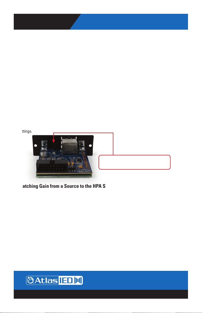
Selecting the dBFS Reference on the HPA-DAC2
The HPA-DAC2 comes with a choice of dBFS (Decibels Full Scale) gain selections of 0dBFS = 10dBu
and 0dBFS = 20dBu. Factory default for the card is 0dBFS = 20dBu. There is a 2-pin header on the
card that is the OdBFS gain selection. When a shunt is applied to the header, the 0dBFS = 20dBu
setting is engaged. When the shunt is removed the setting is 0dBFS = 10dBu. Most pro audio
equipment gains are in the range of 20dBu – 24dBu. Read the entire manual to understand these
settings.
Shunt on 0dBFS = 20dBu, factory default
Shunt off 0dBFS = 10dBu
Matching Gain from a Source to the HPA Series Amplier In a Dante™ Network
Understanding the gain structure is very important to avoid clipping the audio signal or amplier
output. There are three potential ways to clip the signal chain.
1. Amplier Input Clipping - This occurs when the applied input signal exceeds the maximum input
level of the amplier input stage.
2. Amplier Output Clipping - Driving the amplier to maximum output level using the factory default
requires 0dBu or .775V of signal when the channel level control is set to maximum or the all up fully
clockwise. Note: AtlasIED recommends the level to be set with the level being controlled from
the source. Exceeding .775V or 0dBu level will cause the amplier output stage to clip.
3. Digital Clipping - This occurs when the 0dBFS levels are exceeded. This is very important to
understand. Several examples are provided to help understand digital to analog gain structure.
Note: AtlasIED recommends to always place a limiter set for 0dB in the signal path prior to the
Network Output of the transmitting device. This is the best way to prevent clipping the HPA-DAC2.
1601 Jack McKay Blvd. • Ennis, Texas 75119 U.S.A.
Telephone: 800.876.3333 • Fax: 800.765.3435
AtlasIED.com – 3 –
Specifications are subject to change without notice.
Page 4

Dante
HPA-DAC2
™
Accessory Card
Owner’s Manual
HPA-DAC2 Card Installation
Note: Accessory card installation must be done by a qualied technician.
1. Remove the HPA amplier from the AC mains source. Note: In standby mode there are DC voltages
present. The HPA amp must be removed from the AC Mains source in order to prevent damage to
the card or amplier.
2. Remove the two screws (M3 x 8mm Pan Head Black) holding the HPA Accessory blank panel.
3. Remove the ribbon cable from the cover plate.
4. Connect the accessory card to the ribbon cable by carefully aligning the ribbon cable connector to
the mating PCB connector. Do not force. If aligned correctly the cable will mate easily.
5. Carefully guide the accessory card into the slot without forcing the PCB or cable.
6. After the card is inserted and the accessory panel is ush to the chassis, align the two screw
holes and secure them together by inserting two M3 x 8mm screws.
1601 Jack McKay Blvd. • Ennis, Texas 75119 U.S.A.
Telephone: 800.876.3333 • Fax: 800.765.3435
AtlasIED.com – 4 –
Specifications are subject to change without notice.
Page 5

Owner’s Manual
Dante
HPA-DAC2
™
Accessory Card
The following example illustrates an AtlasIED BlueBridge® digital signal processor sending audio
over the network via Dante™ to an optional HPA-DAC2 Dante™ card.
Please note the following:
1. Audio signal is applied to the analog input of the BlueBridge® DSP. For this example, a .775V / 0dBu
signal was applied.
2. The analog signal is converted to digital in the DSP domain, processed and routed onto the Dante™
Network output of the BlueBridge® DSP. The signal chain throughout the BlueBridge® DSP is kept
at 0dBu.
3. The Dante™ Network output or Transmitter level is set for a maximum signal of 0dBu and remains
the same through transmission through the network without any signal degradation or amplitude
loss. The input sensitivity of the HPA ampliers is 0dBu / .775V. This means the analog input signal
to the amp is set properly to achieve full power output from the amplier without clipping any part
of the signal chain.
Router Switch
LAN
BlueBridge BB-88DT
HPA4202 Amplier
Zone 1 CH1 Zone 2 CH2
AtlasIED AH Series
stadium horns with pole
mount hardware
Mic
Optional 2 Channel Dante™ Card
(Receiver)
HPA-DAC2
1601 Jack McKay Blvd. • Ennis, Texas 75119 U.S.A.
Telephone: 800.876.3333 • Fax: 800.765.3435
Dante™
Digital Audio
for additional speakers
Up to 300'
Plenty of power
in each zone
Dante™
Digital Audio
AtlasIED.com – 5 –
Specifications are subject to change without notice.
Page 6

Dante
HPA-DAC2
™
Accessory Card
Owner’s Manual
HPA Setup after HPA-DAC2 Installation
1. Please read the HPA manual prior to proceeding. It is important to set the input levels within the
system to avoid clipping the amplier input or the output HPA-DAC2 card. Note: The best way to
prevent clipping the HPA-DAC2 is to place a limiter set for 0dB in the signal path prior to the
network output of the transmitting device (always recommended).
2. Set the HPA-DAC2 card to 0dBFS = 20dBu. The shunt needs to be on.
3. Set the HPA amplier input sensitivity to .775V. (This is the factory default setting)
4. Set the HPA front panel level controls to the max (10) or fully clockwise. The HPA comes with a
front panel level security cover to prevent tampering.
Set Levels to 10
1601 Jack McKay Blvd. • Ennis, Texas 75119 U.S.A.
Telephone: 800.876.3333 • Fax: 800.765.3435
AtlasIED.com – 6 –
Specifications are subject to change without notice.
Page 7

Owner’s Manual
Dante
HPA-DAC2
™
Accessory Card
Connecting the HPA-DAC2 to a Dante™ Network
Refer to the example below on how to connect a simple Dante™ network audio system. There are
three items needed to make a Dante™ network, (1) gigabit router, Dante™ transmitter and a Dante™
receiver. In the illustration example below the AtlasIED BlueBridge® BB-168DT is the transmitter
and the HPA-DAC2 is the receiver. The HPA-DAC2 installed into the HPA amplier becomes the HPA
amplier’s Inputs 1-2. The router and the CAT5e cable connect the devices together.
Figure 5 is a conguration snapshot of the GUI of the BB-168DT. Analog inputs 1-2 are routed to a
limiter, then onto the network outputs 1-2. Where signal goes from the BB-168DT network output is
determined by a separate software called Dante™ Controller. Dante™ Controller is free software that
allows connectivity and signal routing within Dante™ devices.
Note: Always
add a limiter
before the
network output.
Set the limiter
threshold to
0dBu to prevent
clipping the
input of the HPA
amplier.
Figure 5
Figure 6 shows the BB-88DT and HPA-DAC2 on the Dante™ Network. The HPA amplier model
number will not appear in the Dante™ Controller GUI because the amplier is not the recognized
Dante™ device, the HPA-DAC2 is. The accessory card installed in the amplier combines the digital
and analog platforms. The cells that have been connected are indicated by the green highlighted
circle with the check mark. These highlighted cells indicate the routing of the BB-88DT transmitters
01, 02, (BB-88DT network output 1, 2,) to the HPA-DAC2 (Atlas2-0a004b) receiver channels 1, 2
(HPA amplier inputs 1, 2).
Note: Can be
renamed in Dante™
Controller
Figure 6
1601 Jack McKay Blvd. • Ennis, Texas 75119 U.S.A.
Telephone: 800.876.3333 • Fax: 800.765.3435
AtlasIED.com – 7 –
Specifications are subject to change without notice.
Green check circles
indicate a specic
channel connection
between the Dante™
transmitting device
and the Dante™
receiving device.
Page 8

Dante
HPA-DAC2
™
Accessory Card
Owner’s Manual
Setting Levels In The HPA Amplier to Avoid Clipping
It is important to set the input levels within the system to avoid clipping the amplier input or
the output HPA-DAC2 card. Note: The best way to prevent clipping the HPA-DAC2 is to place a
limiter set for 0dB in the signal path prior to the network output of the transmitting device (always
recommended).
1. Set the HPA-DAC2 card to 0dBFS = 20dBu. The shunt needs to be on.
2. Set the HPA amplier input sensitivity to .775V. (This is the factory default setting)
3. Set the HPA front panel level controls to the max or fully clockwise. The HPA comes with a front
panel level security cover to prevent tampering.
4. Most of the time a DSP processor will be used as the Dante™ Transmitter. It is highly
recommended that a limiter is placed before the network output. This is shown in Figure 5. Set
the limiter maximum output to 0dB. This will prevent the amplier input or HPA-DAC2 from
clipping, but will be enough signal to achieve maximum amplier output. Note: The HPA-DAC2
clips at +7dBu.
5. With the HPA front panel levels set to max, increase the source level until the HPA Limit LEDs just
begin to blink, then, back down the source level slightly so Limit LED only blinks occasionally.
6. After the proper source levels have been set, adjust the HPA amplier output level to the desired
sound levels.
Selecting the Router OR Network Switch – Important!
It is extremely important when selecting a router or switch for the Dante™ network; not all routers
or switches are the same. The size of the Dante™ network will inuence which router or switch is
needed to handle network trafc. There are three things to look for at a minimum or system dropouts
may occur. Refer to Audinate® for products they recommend.
1. Gigabit speed.
2. If using a network switch, it must be a “managed switch” type.
3. If using a router with a built-in switch, it should have DD-WRT rmware or Open Source rmware.
1601 Jack McKay Blvd. • Ennis, Texas 75119 U.S.A.
Telephone: 800.876.3333 • Fax: 800.765.3435
AtlasIED.com – 8 –
Specifications are subject to change without notice.
Page 9

Owner’s Manual
Dante
HPA-DAC2
™
Accessory Card
Dante™ Items to Know or Think About
1. Fixed Levels - Signal level cannot be added or reduced within Dante™ Controller. It is strictly a
signal router.
2. What Does 0dBFS Mean - In the previous example, the signal output of the BlueBridge® DSP
onto the Dante™ network is 0dBu, so the signal within the BlueBridge® DSP can be increased by
20dBu before clipping the Dante™ network. This denes the relationship of 0dBFS = 20dBu
(0dB “Full Scale”) from the source, which in this case the source is the BlueBridge® DSP.
When interfacing Dante™ networks, it is very important to know the source and receiver OdBFS
specication.
3. HPA-DAC2, -10dB Setting - If the setup is identical as described above, but the HPA-DAC2 card is
set to 0dBFS = 10dBu, how would that affect a HPA amplier? The signal coming into the HPA
amp would be -10dB down and the amp could never reach full output because the HPA amplier
requires 0dBu to reach full output power. To correct the low input level to the amp, increase the
signal from the source (BlueBridge® DSP) by 10dBu. Keep in mind within BlueBridge® there is only
10dBu of headroom before digitally clipping the input of the HPA-DAC2. Be careful when adding
EQ boost. If adding 6dB of EQ boost at 100Hz, there is only 4dB of headroom at 100Hz before
clipping. If the HPA-DAC2 was set to 20dBu = 0dFS there would be 14dB of headroom at 100Hz.
This is why it’s so important to know the OdBFS reference points between devices in the Dante™
network.
4. Industry Standard - At the time of this information, there is no industry standard between
companies for scaling 0dBFS gain levels in equipment. In a digital studio this is usually not an
issue because most of the same brand is used or a limited number of products are interfaced.
However, with live sound or commercial audio there can be multiple brands used in one job.
Dante™ can be great for connectivity between devices but be aware of gain structure matching.
5. Interfacing Data with Different Manufactures Equipment - To help understand scaling here are
some examples:
• Source device 0dBFS = 20dBu, transmits to a receiver with a 0dBFS = 20dBu reference, the
output is 0dBu. This scenario is ideal when using the HPA ampliers.
• Source device 0dBFS = 20dBu, transmits to a receiver with a 0dBFS = 10dBu reference, the
output is -10dBu. To get full output of the HPA ampliers you have to increase the network
output levels by 10dBu to get 0dBu into the HPA ampliers input.
• Source device 0dBFS = 10dBu, transmits to a receiver with a 0dBFS = 20dBu reference, the
output is +10dBu. This combination will give too much signal into the HPA amplier. Reduce the
signal from the DSP Network output.
• Source device 0dBFS = 10dBu, transmits to a receiver with a 0dBFS = 10dBu reference, the
output is 0dBu. This scenario is ideal when using ampliers with .775V input sensitivity.
1601 Jack McKay Blvd. • Ennis, Texas 75119 U.S.A.
Telephone: 800.876.3333 • Fax: 800.765.3435
AtlasIED.com – 9 –
Specifications are subject to change without notice.
Page 10

HPA-DAC2
™
Dante
6. Understanding Digital Noise vs Headroom - If headroom before clipping is a concern, the higher
the ratio between OdBFS and output level, the less likely clipping will be an issue. If the
application is paging and background music then a lower number is ok because the headroom is
not as critical. In live sound reinforcement applications such as a church band or a concert, more
headroom and gain is needed for dynamics. The issue with higher gain in a product is the higher
the gain the higher the noise output. To combat high gain output noise, use a Dante™ Transmitter
product with good signal to noise ratio specication, such as 100dB or better. For instance,
AtlasIED BlueBridge
amplied, assuring low noise out of the HPA amplier. Look at the input and output 0dBFs
reference points and the noise oor specication. If they are not listed call the manufacturer.
Accessory Card
®
DSP has a signal to noise ratio of 110dB. The noise is very low before it is
Owner’s Manual
Specications
Description 2 input Dante™ receiver card for the HPA Series amplifiers
Connection Single RJ-45
Cable Quality CAT-5
Gain Settings 0dBFS = 20dBu & 0dBFS = 10dBu PCB shunt selectable
Indicators Ethernet network activity LED green / yellow
Amplifier Interface 16 pin HPA amplifier connections
Electrical Specifications
Dante™ Transmission Speed 100Mbps
Frequency Response 20Hz - 20KHz +/- 1dB
THD .06% @ 1KHz
Maximum Output Level 7dBu
Noise 10dB Gain Setting = -83dBu
20dB Gain Setting = -77dBu
Mechanical
Dimension H 0.97" x W 2.7" x D 2.5" (H 24.6mm x W 68mm x D 63mm)
Weight 2.6oz (.07kg)
Color Black
Material Steel
1601 Jack McKay Blvd. • Ennis, Texas 75119 U.S.A.
Telephone: 800.876.3333 • Fax: 800.765.3435
AtlasIED.com – 10 –
Specifications are subject to change without notice.
Page 11

Owner’s Manual
Notes:
Dante
HPA-DAC2
™
Accessory Card
1601 Jack McKay Blvd. • Ennis, Texas 75119 U.S.A.
Telephone: 800.876.3333 • Fax: 800.765.3435
AtlasIED.com – 11 –
Specifications are subject to change without notice.
Page 12

Dante
HPA-DAC2
™
Accessory Card
Owner’s Manual
Limited Warranty
All products manufactured by AtlasIED are warranted to the original dealer/installer, industrial or
commercial purchaser to be free from defects in material and workmanship and to be in compliance
with our published specifications, if any. This warranty shall extend from the date of purchase
for a period of three years on all AtlasIED products, including SOUNDOLIER brand, INNOVATIVE
ELECTRONIC DESIGNS brand, and AtlasIED brand products except as follows: one year on
electronics and control systems; one year on replacement parts; and one year on Musician Series
stands and related accessories. Additionally, fuses and lamps carry no warranty. AtlasIED will solely
at its discretion, replace at no charge or repair free of charge defective parts or products when the
product has been applied and used in accordance with our published operation and installation
instructions. We will not be responsible for defects caused by improper storage, misuse (including
failure to provide reasonable and necessary maintenance), accident, abnormal atmospheres, water
immersion, lightning discharge, or malfunctions when products have been modified or operated
in excess of rated power, altered, serviced or installed in other than a workman like manner. The
original sales invoice should be retained as evidence of purchase under the terms of this warranty.
All warranty returns must comply with our returns policy set forth below. When products returned to
AtlasIED do not qualify for repair or replacement under our warranty, repairs may be performed at
prevailing costs for material and labor unless there is included with the returned product(s) a written
request for an estimate of repair costs before any nonwarranty work is performed. In the event of
replacement or upon completion of repairs, return shipment will be made with the transportation
charges collect.
EXCEPT TO THE EXTENT THAT APPLICABLE LAW PREVENTS THE LIMITATION OF CONSEQUENTIAL
DAMAGES FOR PERSONAL INJURY, ATLASIED SHALL NOT BE LIABLE IN TORT OR CONTRACT
FOR ANY DIRECT, CONSEQUENTIAL OR INCIDENTAL LOSS OR DAMAGE ARISING OUT OF THE
INSTALLATION, USE OR INABILITY TO USE THE PRODUCTS. THE ABOVE WARRANTY IS IN LIEU OF
ALL OTHER WARRANTIES INCLUDING BUT NOT LIMITED TO WARRANTIES OF MERCHANTABILITY
AND FITNESS FOR A PARTICULAR PURPOSE.
AtlasIED does not assume, or does it authorize any other person to assume or extend on its behalf,
any other warranty, obligation, or liability. This warranty gives you specific legal rights and you may
have other rights which vary from state to state.
Service
Should your HPA-DAC2 require service, please contact the AtlasIED warranty department at
1-877-689-8055, ext. 277 or support.atlassound.com to obtain an RA number.
AtlasIED Tech Support can be reached at 1-800-876-3333 or support.atlasied.com.
Visit our website at www.AtlasIED.com to see other AtlasIED products.
©2017 Atlas Sound L.P. The Atlas “Circle A”, Soundolier, and Atlas Sound are trademarks of Atlas Sound L.P.
IED is a registered trademark of Innovative Electronic Designs LLC. All Rights Reserved. All other trademarks are the property of their
AtlasIED.com – 12 –
respective owners. All specs are subject to change without notice. ATS005441 RevB 4/17 P/N 493662
1601 Jack McKay Blvd. • Ennis, Texas 75119 U.S.A.
Telephone: 800.876.3333 • Fax: 800.765.3435
Specifications are subject to change without notice.
 Loading...