

Atlantic alfea hybrid duo 11, alfea hybrid duo 14, alfea hybrid duo 16, WOYG112LCT, WOYK112LCT Installation And Commissioning Instructions
...
alféa hybrid duo oil low NOx
Document n° 1605-3 ~ 17/09/2013
FR EN ES PT IT
Water/air heat pump
with integrated fuel oil burner,
single phase or three phase
split, 2 services
Outdoor unit Hydraulic module
WOYG112LCT 024208
WOYG140LCT
WOYK112LCT
WOYK140LCT
WOYK160LCT
ES ES ES ES
Installation and
commissioning
instructions
for professionals
To be kept by the user
for future reference
atlantic-comfort.com
The specications of this equipment may
be modied without prior instructions
Non-contractual document.

alfea hybrid duo heat pump oil low NOx CH
Contents
Presentation of the equipment . . . . . . . . . . . . . . . . . . . . . . . . .4
Packaging . . . . . . . . . . . . . . . . . . . . . . . 4
Optional equipment . . . . . . . . . . . . . . . . . . 4
Scope . . . . . . . . . . . . . . . . . . . . . . . . . 4
Denitions . . . . . . . . . . . . . . . . . . . . . . . 4
General characteristics . . . . . . . . . . . . . . . .4
Description. . . . . . . . . . . . . . . . . . . . . . . 9
Operating principle . . . . . . . . . . . . . . . . . 11
Installation . . . . . . . . . . . . . . . . . . . . . . . . . . . . . . . . . . . 13
Statutory conditions
for installation and servicing in France . . . . . . . . . . .13
Statutory conditions
for installation and servicing in Belgium . . . . . . . . . . 13
Use of new fuel oil types. . . . . . . . . . . . . . . 13
Reception . . . . . . . . . . . . . . . . . . . 13
Handling . . . . . . . . . . . . . . . . . . . 13
Accessories supplied . . . . . . . . . . . . . 13
Containment of refrigerant circuits . . . . . . 14
Positioning . . . . . . . . . . . . . . . . . . . . . . 14
Installation de the outdoor unit . . . . . . . . . . . 14
Installation precautions . . . . . . . . . . . . 14
Fitting the outdoor unit . . . . . . . . . . . . 16
Connecting the
condensates drain . . . . . . . . . . . . . . 16
Installation of the Hydraulic module . . . . . . . . . 16
Requirements to installation space . . . . . . 16
Reversible chamber door . . . . . . . . . . . 17
Evacuation pipe . . . . . . . . . . . . . . . . 17
Connection pipe . . . . . . . . . . . . . . . 18
Refrigerating connections . . . . . . . . . . . . . . 18
Rules and precautions . . . . . . . . . . . . 18
Refrigerating connections. . . . . . . . . . . 18
Flaring . . . . . . . . . . . . . . . . . . . . 19
Forming the refrigerant tubes . . . . . . . . . 19
Connecting the are connections . . . . . . . 20
Commissioning the refrigerating gas installation . . 21
Start procedure . . . . . . . . . . . . . . . . 21
Final leak test . . . . . . . . . . . . . . . . . 22
Additional volume added . . . . . . . . . . . 23
Collecting the refrigerating
uid in the outdoor unit . . . . . . . . . . . . 23
Hydraulic connection . . . . . . . . . . . . . . . . 24
General . . . . . . . . . . . . . . . . . . . . 24
Connection to the domestic circuit . . . . . . 25
Rinsing the installation . . . . . . . . . . . . 25
Filling and draining the installation . . . . . . 25
Connection of the fuel supply . . . . . . . . . . . . 26
Electrical connections . . . . . . . . . . . . . . . . 26
Characteristics of the electrical power supply 26
General remarks on the electrical connections 26
Overall view of the electrical connections . . . . .27
Cross section of the cable and protection rating 27
Electrical connections on the
outdoor unit side for single phase model. . . 28
Electrical connections on the
outdoor unit side for 3 phase model . . . . . 29
Electrical connections
on Hydraulic module side . . . . . . . . . . 30
Outdoor sensor . . . . . . . . . . . . . . . . . . . 33
Ambient sensor and/or central ambient unit (radio) . 33
Verications and commissioning . . . . . . . . . . 34
Setting the burner . . . . . . . . . . . . . . . . . . 35
Setting the electrodes . . . . . . . . . . . . 35
Setting the combustion air . . . . . . . . . . 35
Conguration of the Ambient probe . . . . . . . . . 35
Conguration of the central ambient unit (radio) . . 35
- 2 -
Installation and operating manual "1605 - EN"
alfea hybrid duo heat pump oil low NOx CH
" The following are required for the installation of this appliance:
- work must only be carried out by qualied personnel with a certicate of aptitude for handling
refrigerating uids (in compliance with article R543.106 of the Environmental code),
- a heating technician must be involved.
Regulation . . . . . . . . . . . . . . . . . . . . . . . . . . . . . . . . . . . 36
The user interface, the ambient sensor (option)
and the central ambient unit (option) . . . . . . . . 36
Description of the display . . . . . . . . . . . . . . 38
Water logic . . . . . . . . . . . . . . . . . . . . . . 38
Manual setting . . . . . . . . . . . . . . . . 38
Regulation parameters . . . . . . . . . . . . . . . 40
General . . . . . . . . . . . . . . . . . . . . 40
Setting the parameters . . . . . . . . . . . . 40
List of function lines
(settings, diagnosis, state) . . . . . . . . . . 40
Overall view of the electrical connections . . . . . . . . . . . . . . . . . . 52
Electrical wiring diagrams . . . . . . . . . . . . . . . . . . . . . . . . . . . 54
Breakdown diagnosis and information . . . . . . . . . . . . . . . . . . . . 57
Faults displayed on the Hydraulic module . . . . . . 57
Faults displayed
on the single phase outdoor unit . . . . . . . . . . 58
Faults displayed
on the 3 phase outdoor unit . . . . . . . . . . . . . 59
Display information . . . . . . . . . . . . . . . . . 60
Servicing of the installation . . . . . . . . . . . . . . . . . . . . . . . . . . 62
Checking the hydraulic circuit . . . . . . . . . . . . 62
Servicing the tank . . . . . . . . . . . . . . . . . . 62
Checking the outdoor unit . . . . . . . . . . . . . . 62
Checking the electrical circuit . . . . . . . . . . . . 62
Servicing of the heat exchanger . . . . . . . . . . . 62
Servicing the burner . . . . . . . . . . . . . . . . . 62
Servicing the chimney . . . . . . . . . . . . 62
Servicing the safety appliances . . . . . . . . 62
Start-up procedure . . . . . . . . . . . . . . . . . . . . . . . . . . . . . . . 64
Start-up check-list . . . . . . . . . . . . . . . . . . 64
Before starting-up . . . . . . . . . . . . . . . 64
Starting-up . . . . . . . . . . . . . . . . . . 65
Settings sheet . . . . . . . . . . . . . . . . . . . . 66
Start-up data sheet . . . . . . . . . . . . . . . . . 67
Values to be given to the user . . . . . . . . . . . . . . . . . . . . . . . . . 68
Installation and operating manual "1605 - EN" - 3 -
alfea hybrid duo heat pump oil low NOx CH
1 Presentation of the equipment
1.1 Packaging
• 1 box: Outdoor unit.
• 1 box: Hydraulic module with NOx low burner and
outdoor temperature probe.
Pairing table
Heat pump Outdoor unit Hybrid duo hydraulic module
Model ref. export ref. Code ref. Code
alféa hybrid duo 11 single phase 522 694 WOYG112LCT 700117
alféa hybrid duo 14 + single phase 522 695 WOYG140LCT 700142
alféa hybrid duo 11 three phase 522 696 WOYK112LCT 700118
alféa hybrid duo 14 three phase 522 697 WOYK140LCT 700143
alféa hybrid duo 16 three phase 522 698 WOYK160LCT 700163
MH-HD 024208
1.2 Optional equipment
• 2nd circuit kit (ref. 073953).
- to connect 2 heating circuits.
• Ambient probe T55 (ref. 073951) or
Ambient probe radio T58 (ref. 075313).
- to correct the ambient temperature.
• Central ambient unit T75 (ref. 073954) or
Central radio ambient unit T78 (ref. 074061).
- to correct the ambient temperature
and programme the PAC.
• Anti-vibration pins (ref. 523574).
• Floor support in white PVC (ref. 809532).
• Duo pool kit (ref. 074064).
• High ow circulator kit (ref. 073959).
- for a 1 circuit heated oor installation
with a PAC model 13 and 16.
1.3 Scope
1.4 Denitions
- Split: the heat pump is composed of two parts (an
outdoor unit to be located outdoors and a Hydraulic
module to be installed inside the home).
- Air/water: the outdoor air is the energy source .
This energy is transmitted to the heating water by the
heat pump.
- Inverter: the fan and compressor speeds are modulated
to suit the heat requirements. This technology
economises energy and permits operation with single
phase power supply, regardless of the power rating
of the heat pump, by avoiding high current demands
when started.
- COP (coefcient of performance: this is the ratio
between the energy transferred to the heating circuit
and the electrical energy consumed.
- hybrid: the Hydraulic module operates with dual energy
(air/water heat pump and integrated oil boiler).
- low NOx: Burner designed to minimise the emission
of Nitrogen oxides NOx in the fumes. Generally low
This heat pump permits:
- heating in winter,
- the production of sanitary hot water,
- controlling two heating circuits *,
NOx burners are considered to be burners whose
emission rate is below the most severe regulations at
that time. This limit chnages regularly according to the
regulations and technical progress.
- heating the pool*.
*: These options require the use of additional kits
(see § "optional equipment").
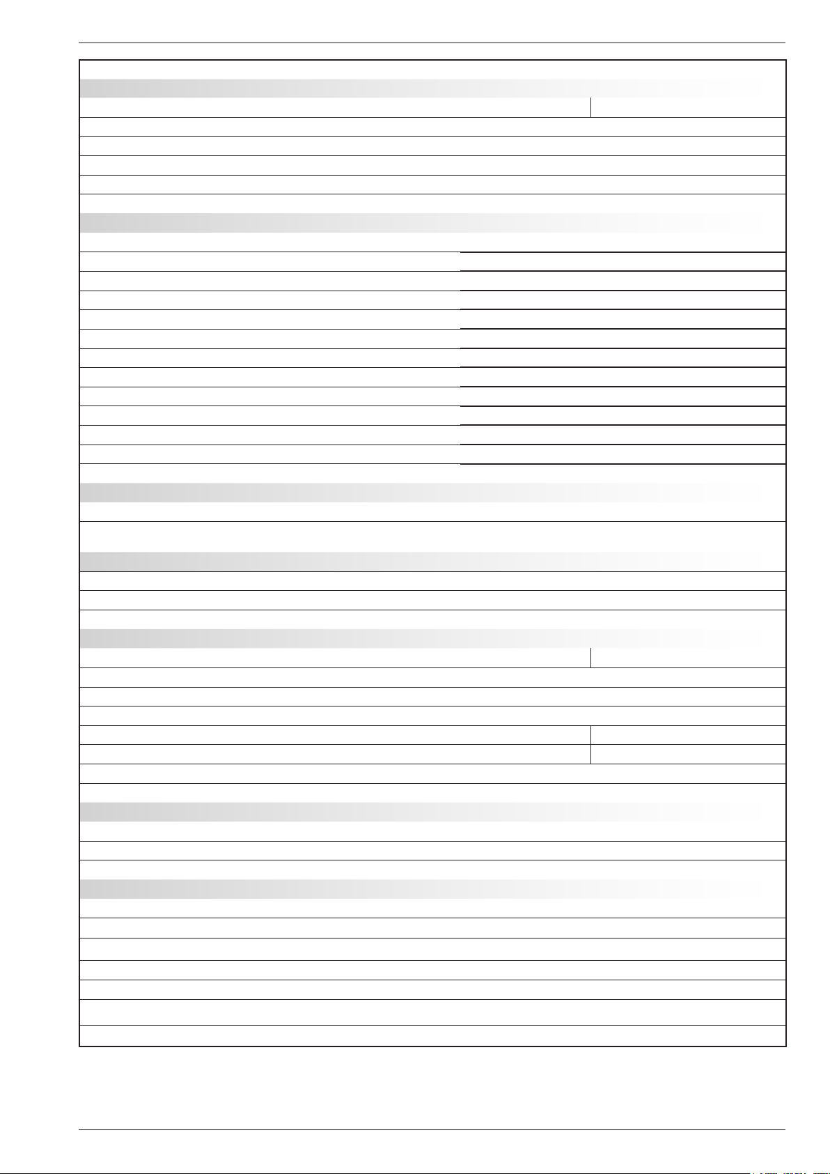
1.5 General characteristics
Denomination : alféa hybrid duo oil low NOx ue model 11 14 + 11 3 ph. 14 3 ph. 16 3 ph.
Nominal heating performances (Outdoor T° / initial T°) - Heating power
+7 °C/+35°C - under-oor heating kW 10.30 13.50 10.60 13.25 14.89
-7 °C/+35°C - under-oor heating kW 10.10 11.22 9.75 13.00 13.50
+7 °C/+45°C - LT radiators kW 9.05 11.32 10.10 12.60 13.00
-7 °C/+45°C - LT radiators kW 8.33 10.41 8.66 12.50 13.00
Nominal heating performances (Outdoor T° / initial T°) - Absorbed power
+7 °C/+35°C - under-oor heating kW 2.57 3.50 2.68 3.20 3.70
-7 °C/+35°C - under-oor heating kW 3.94 4.68 3.69 5.18 5.40
+7 °C/+45°C - LT radiators kW 2.82 3.69 3.01 3.81 4.00
-7 °C/+45°C - LT radiators kW 4.05 5.24 4.04 6.00 6.37
Coefcient of performance (COP) (+7 °C / + 35 °C) 4.00 3.86 3.95 4.14 4.02
- 4 -
Installation and operating manual "1605 - EN"
alfea hybrid duo heat pump oil low NOx CH
Denomination : alféa hybrid duo oil low NOx ue model 11 14 + 11 3 ph. 14 3 ph. 16 3 ph.
Electrical characteristics
Voltage (50 HZ) V 230 400
Maximum current of the appliance A 22 25 8.5 9.5 10.5
Nominal current A 11.4 14.2 3.7 4.8 5.5
Real absorbed power by the fan W 2x100 2x10⁴
Real absorbed power by the circulator W 151
Real absorbed power by the outdoor unit W 5060 5750 5865 6555 7245
Burner (low NOx), Combustion chamber, ue
Fuel ow rate kg/h 2.3
Nominal caloric ow rate kW 28.0
Jet Danfoss 0.55 gph - 80°S
Pump Suntec AS 47
Factory set pressure bar 15
Combustion chamber (diameter / Length) mm 270 / 400
Combustion chamber (Volume) dm
Volume on smoke side dm
3
3
22.9
31.1
Number of turbulators in the exchanger - 7
Temperature of the smoke °C 190
Mass ow rate of the smoke kg/h 44.4
Boiler pressure Pa 3 to 5
Optimum low pressure in the chimney Pa 15
Hydraulic circuit
Maximum heating operating pressure bar 3
Hydraulic circuit ow rate (min./max.) for 4°C<Δt<8°C
(nominal conditions)
l/h 1170 / 2340 1460 / 2920 1170 / 2340 1460 / 2920 1650 / 3290
Domestic hot water tank
Capacity of domestic hot water tank litre 125
Max. operating pressure bar 7
Specic ow rate (in boiler mode only) l/mn 19
Miscellaneous
Weight of the outdoor unit kg 92 99
Weight of the hydraulic module (empty/with water) kg 215 / 482
Capacity in water of the heating body litre 142
Expansion vessel litre 18
Noise level at 1 m 1 ( hydr. mod. in thermodynamic oper.) dB 35.5 35.5
Acoustic power as per EN 12102 2 (hyd. module) dB 43.3 43.3
Noise level at 5 m 1 (outdoor unit) dB 42 43 39 41 42
Acoustic power as per EN 12102 2 (outdoor unit) dB 69 70 66 68 69
Heating system operating limits
Min./max. outdoor temperature °C -25 / +35
Max. water temperature thermodynamic mode °C 60
Max. water temperature for start of heating °C 80
Refrigerating circuit
Diameters of the gas pipes inches 5/8
Diameters of the liquid pipes inches 3/8
Factory volume added of refrigerating uid R410A
3
g 2500
Max. operating pressure bar 41.5
Min. length of pipes m 5
Max. length of pipes
Max. length of pipes 5 / Max. height diff.
1
Sound pressure level at (x) m from the appliance, 1.5m from the ground,
4
5
free eld directivity 2.
2
the acoustic power is a laboratory measurement of the power of the
sound emitted but contrary to the sound level, it does not correspond
to the measurement of what is felt.
m 15
m 20 / 20
3
refrigerating uid R410A in compliance with standard NF EN 378.1.
4
factory volume of refrigerating uid R410A.
5
Taking into account the possible extra volume of refrigerating uid
R410A (see § 2.8.3, page 22).
Installation and operating manual "1605 - EN" - 5 -
alfea hybrid duo heat pump oil low NOx CH
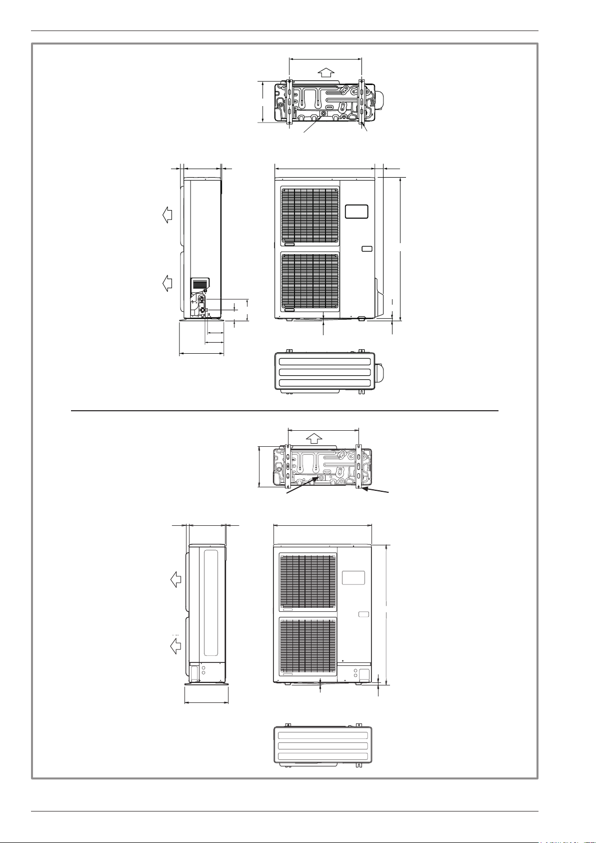
" outdoor unit,
model hybrid duo oil low NOx 11
model hybrid duo oil low NOx 14 +
Drain hole (Ø 20) 4 holes (Ø 10)
31 7790033012
AIR
Air
AIR
Air
400
Vu ede côté
Side view
650
AIR
Air
370
Orifice d’écoulement(Ø 20) 4 trousØ10
3/8”
5/8”
196
99
147
170
Vu ede dessous
Bottom view
9
Vu edeface
Front view
1290
21
" outdoor unit,
model hybrid duo oil low NOx 11 3 phase,
model hybrid duo oil low NOx 14 3 phase,
model hybrid duo oil low NOx 16 3 phase
Drain hole (ø 20)
31 12330
AIR
Air
AIR
Air
400
Side view
370
Top view
Vu ede dessus
650
Air
Bottom view
900
9
Front view
4 holes (ø 10)
1290
21
- 6 -
Top view
gure 1 - Dimensions in mm
Installation and operating manual "1605 - EN"
alfea hybrid duo heat pump oil low NOx CH
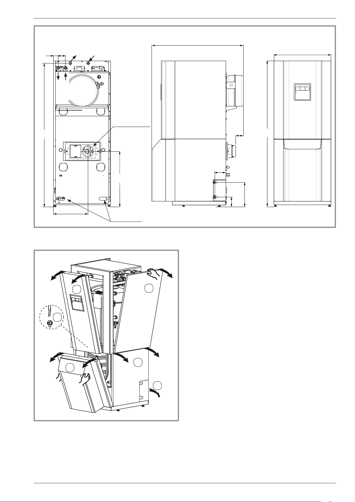
" Hydraulic module
Flexible hoses
Ø 20x27 female
Start
DHW
Ø 26x34
male
Return
EFS
Ø int. ext. smoke
outlet 125 / 139
53 86
1682
651
1075
130
91
Liquid 3/8”
670
1711
2
405
3
1
Fuel hose
passages
gure 2 - Dimensions in mm
4
6
Gas 5/8”
115
287
Front viewSide viewRear view
5
gure 3 - Remove the panel
Installation and operating manual "1605 - EN" - 7 -
alfea hybrid duo heat pump oil low NOx CH
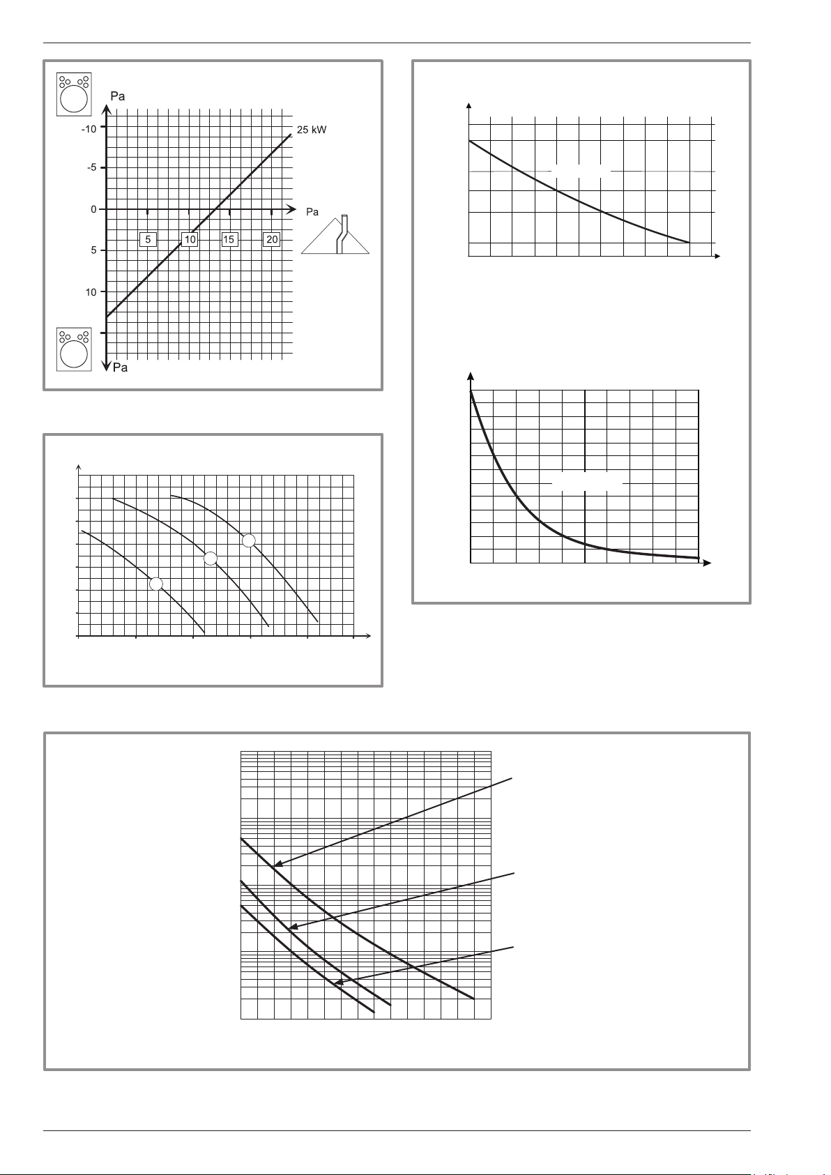
outdoor probe QAC34
Ω
43907
gure 7 - Head losses of the combustion circuit
mbar
600
500
400
300
200
100
0
1mbar =10 mmCE=100 Pa
2
1
1
3
1,5 2 2,50,50
m/h
10000
2490
1000
338
-50 -25 0 25 50 75 °C
1 kΩ, 25 °C
Heat pump return sensor
Heat pump start sensor
Ω
32500
30000
27500
25000
22500
20000
17500
15000
12500
10000
7500
5000
2500
0
0 10 20 30 40 50 60 70 80 90 100 °C
gure 5 - Ohmic value of the probes
3
10 kΩ, 25 °C
(Hydraulic module)
gure 4 - Hydraulic pressures and
ow rates available
10000
1000
Ohmic value (kΩ)
100
10
1
-20 -10 0 10 20 30 40 50 60 70 80 90 100 110 120 130
gure 6 - Ohmic value of the sensors (outdoor unit)
- compressor
- Discharge
- Condensation
- Outdoor
- Evaporator outlet
- Evaporator medium
- Compressor housing
temperature °C
- 8 -
Installation and operating manual "1605 - EN"
alfea hybrid duo heat pump oil low NOx CH
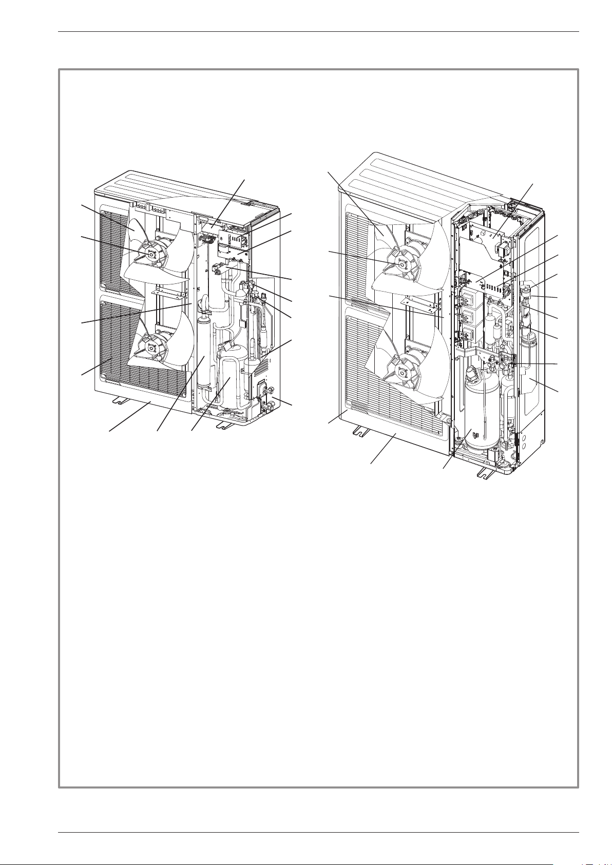
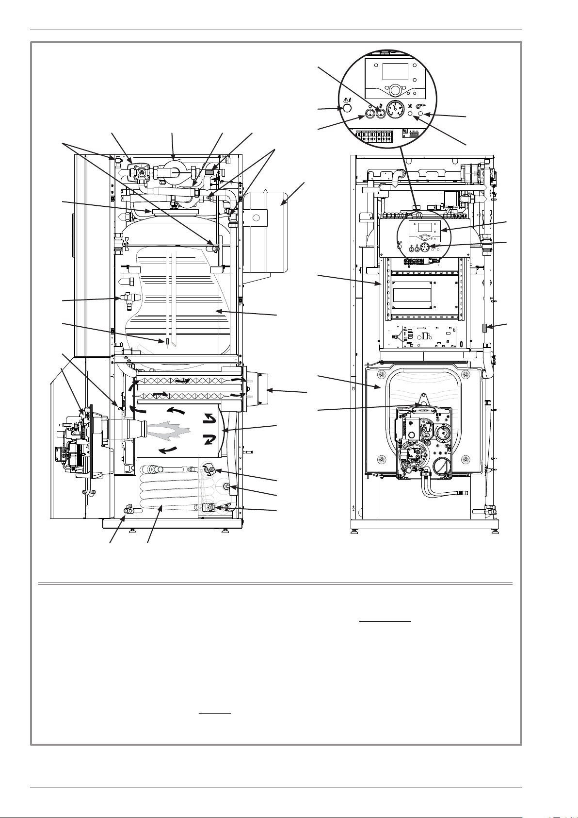
1.6 Description
" Model
hybrid duo oil low NOx 11 and 14 + single phase
3
1
2
13
8
11
5
4
7
15
14
9
" Model
hybrid duo oil low NOx 11, 14 and 16 3 phase
1
2
13
WO*K1**LCT
3
4
5
14
15
9
7
11
6
8
12
6
10
12
10
Legend:
1. High performance impeller and low noise level.
2. Electrical motor with variable "inverter" operation.
3. "Inverter" command module.
4. Control LEDs and buttons.
5. Connector terminals (power supply and interconnection).
6. Storage bottle for refrigerating uid.
7. Four way valve.
8. Panels treated against corrosion.
9. Electronic pressure regulator of the main circuit.
10. "Inverter" compressor acoustically and thermally insulated with liquid injection port.
11. Refrigerating connection taps (are connector) with protective cover.
12. Retention tank with drain hole of the condensates.
13. Evaporator with high performance exchange surfaces; aluminium ns with anti-corrosion and
hydrophilic treatments, grooved copper tubes.
14. Solenoid valve for injection of liquid.
15. Electronic pressure regulator for injection of liquid.
gure 8 - Parts of the outdoor unit
Installation and operating manual "1605 - EN" - 9 -
alfea hybrid duo heat pump oil low NOx CH
28
16
11
15
24
19
12 13
22
26
27
17
30
31
18
25
29
20
10
23
6
8
5
14
Legend
1. Condenser
2. Liquid refrigeration connection
3. Gas refrigeration connection
4. Combustion chamber
5. Reversible chamber door
6. Chamber pressure socket
7. Flame viewer
8. Burner low NOx
9. Evacuation of smoke (ue)
10. Domestic hot water tank
11. Inspection trap of the domestic hot
water tank
1
9
7
4
2
21
3
12. Heating circulation pump
13. Domestic circulation pump
14. Drain valve
15. Safety valve
16. Manual drain tap
17. Non-return valve
18. Expansion vessel
19. Mixer valve CC1
20. Electrical housing
Sensors
21. Condensation sensor
22. heating circuit1 start sensor
23. Heater start sensor
24. Domestic sensor
Control panel
25. User interface
26. Reset button
(overheating safety device)
27. Start/Stop switch
28. "Sweeping" button
29. Pressure gauge
30. Burner on LED (green)
31. Burner safety LED (red)
- 10 -
gure 9 - Parts of the hydraulic module
Installation and operating manual "1605 - EN"
alfea hybrid duo heat pump oil low NOx CH
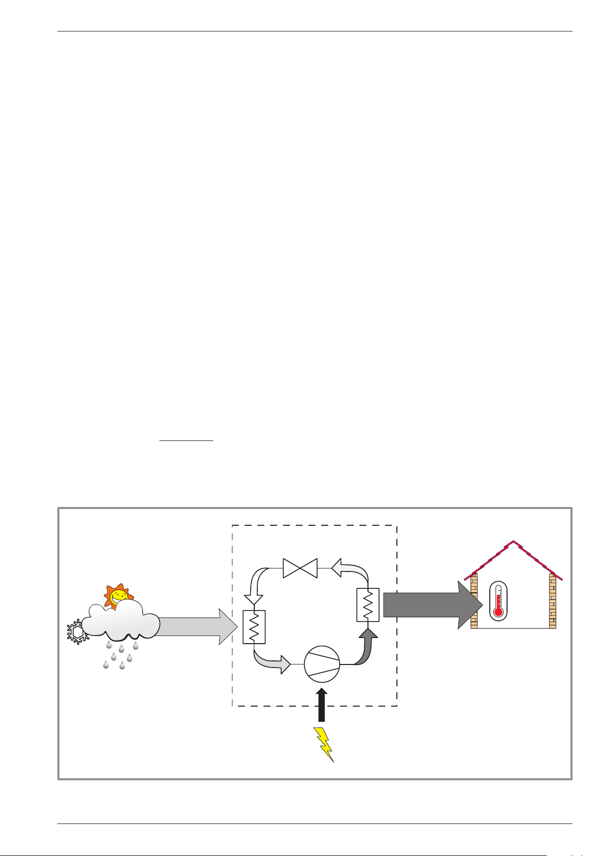
1.7 Operating principle
The heat pump transmits the energy in the outdoor air
to the home to be heated.
The heat pump is formed of four main elements inside
which a refrigerating uid circulates (R410A).
- In the the evaporator (item. 13, gure 8, page 9):
The calories are taken from the outdoor air and
transmitted to the refrigerating uid. As its boiling point
is low, it changes from the liquid state to the vapour
state, even when the weather is cold.
- --In the compressor (item 10 or 16, gure 8, page 9):
The vaporised refrigerating uid is pressurised and
thus carries more calories.
- In the condensor (item 1, gure 9): The energy in the
refrigerant is transmitted to the heating circuit. The
refrigerating uid returns to its liquid state.
- In the pressure regulator (item 9 or 15, gure 8, page 9):
The liqueed refrigerating uid is taken to low pressure
and returns to its initial temperature and pressure.
The heat pump has a regulator that controls the indoor
temperature based on the measurement of the outdoor
temperature, regulation by water logic. The ambient
sensor (optional) provides a corrective action to the
water logic.
The Hydraulic module is tted with a burner that has an
AON operation, on demand from the regulator:
- to provide additional heating during the colder
periods,
- to provide support for the domestic (DHW) or
- to take over on "Peak Tariff" days (load shedding
function or EJP, see page 30).
Priority is given to the operation of the heat pump.
When the heat pump is not sufcient for the heating, the
burner automatically takes over.
• Regulation functions
- The initial temperature of the heating circuit is
controlled by water logic.
- In function of an initial heating temperature, the power
of the outdoor unit is modulated via the "inverter"
compressor.
- Management of the supplementary heating.
- The daily timer programme allows comfort or reduced
ambient temperature periods.
- Switching between summer/winter operation is
automatic.
- Domestic hot water: Timer heating programme,
management of operation of the DHW circulation
pump.
- Ambient sensor*: The ambient sensor provides a
corrective action to the water logic.
- Management of a 2nd heating circuit*.
- Management of the heating of the swimming pool*.
*When the PAC (heat pump) is tted with associated options and kits
• Protection functions
- Anti-legionella cycle for the domestic hot water.
- A pressure switch monitors the hydraulic pressure.
If the pressure is below 0.5 bar, an error message is
displayed (369) and the heat pump is stopped.
PAC
Dt
Cn
Air energy
gure 10 - Operating principle of a heat pump
Installation and operating manual "1605 - EN" - 11 -
Ev
Electrical
energy
consumed
Cp
COP 4
1kW
4kW
Heat produced
PAC - heat pump
Ev - Evaporator
Cp - compressor
Cn - condenser
Dt - pressure regulator
20 °C
alfea hybrid duo heat pump oil low NOx CH
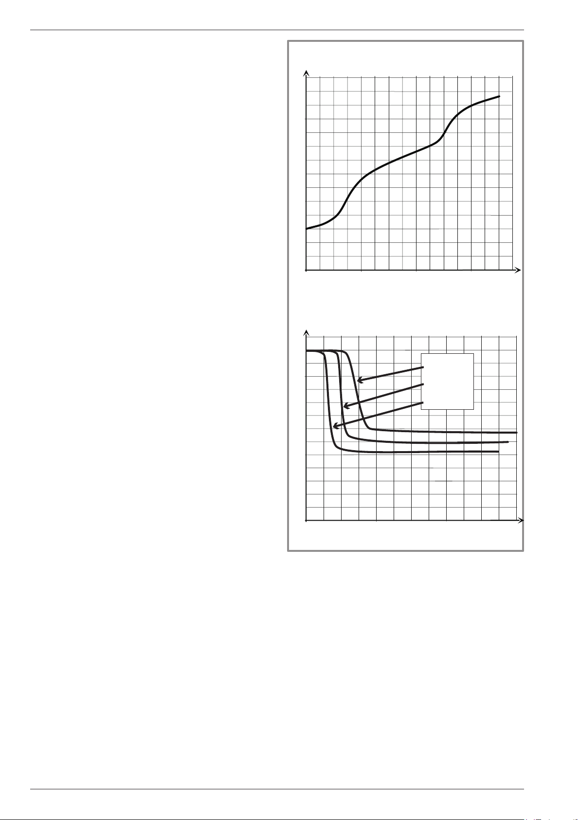
• Operating principle of the domestic hot water
(DHW)
Two sanitary hot water temperatures (SHW)
can be programmed: comfort temperature
(line 1610 at 65 °C) and reduced temperature
(line 1612 àat40 °C).
The default DHW programme (line 560, 561, 562, 563
and 564) is set for a comfort temperature from 0h00
to 5h00 and from 15h00 to 18h00 and a reduced
temperature for the rest of the day.
The reduced temperature value may be useful to avoid
restarting the DHW too many times and for too long
through the day.
The production of domestic hot water (DHW) is started
when the temperature in the tank is 7°C below (setting
of line 5024) the reference value temperature.
The domestic hot water (DHW) is produced by the
heat pump then completed if required by the burner. To
ensure there is an DHW value higher than 45°C, the
burner must be operated.
Depending on the setting of the parameter (1620), the
comfort temperature may be reached either
- 24 h / day,
- in line with the timer programme of the heating
circuit,
- in line with the DHW timer programme,
- during the off peak periods,
- during off-peak periods and depending on the
SHW time programme.
The production of SHW has priority over heating, but the
production of SHW is managed by cycles that regulate
the time spent heating and the production of SHW when
simultaneous demands occur.
A function for switching from "reduced" to "comfort"
is available on the front panel of the user interface
(see item 1, gure 43, page 36).
Increase in temperature of the tank (without drawing)
°C
60
50
40
30
20
10
0
°C
60
50
0
Domestic hot water temperature (with open tab).
60
120 180
10 l/min
12,5 l/min
15 l/min
40
30
20
min
Anti-legionella cycles may be programmed (lines 1640to
1647).
• Fan coil units with integrated regulation
Do not use an ambient sensor in the zone concerned.
10
0
0
gure 11 - Domestic Hot Water performance
15
30
min
- 12 -
Installation and operating manual "1605 - EN"
alfea hybrid duo heat pump oil low NOx CH
2 Installation
2.1 Statutory conditions
for installation and servicing
The appliance must be installed and the maintained
by an approved professional in accordance with the
prevailing regulations and code of practice, in particular:
- The legislation on the handling of refrigerants:
- Heating installation with oor heating system.
carrying out water oor heating systems.
- Low voltage electrical installations - Rules.
- Central heating installations for buildings.
- Sanitary plumbing for homes.
- Calculations for sanitary plumbing installations and
evacuation of rain water.
- Copper pipes. Distribution of cold water and sanitary
hot water, evacuation of dirty water, rain water, climatic
installations.
- Chimney and ue work.
- Rules and processes for calculating chimneys with
natural draft and appendices.
- Chimney for homes.
- Ventilation of homes.
2.3 Unpacking and reserves
2.3.1 Receipt
When the courier is present, carefully check the general
appearance of the appliances, check that the outdoor
unit has not been in horizontal position.
In the event of disagreement, write to the courier within
48 hours mentioning all reserves and send a copy of
this letter to the After Sales Department.
2.3.2 Handling
The outdoor unit must not be in horizontal position
during transport.
Transport in horizontal position creates a risk of damage
to the inner tubes and the compressor suspensions.
Damage caused by transport transport in horizontal
position is not covered by the warranty.
If required, the outdoor unit may be tilted only when
being moved by hand (to get it through a doorway, or
up stairs...).
This operation must be carried out carefully and the
appliance must be immediately returned to the vertical
position.
2.2 Use of new fuel oil types
This boiler and its burner are compatible with the new
domestic oil containing FAME (Fatty Acid Methyl Ester)
and with non-road diesel (NRD*) on the condition they
respect the rules for the use and storage of this fuel
(refer to document n°1474 supplied with the appliance
and the user instructions, § Rules for using and storing
domestic fuel containing FAME).
only FranceNe pas traduire:only France
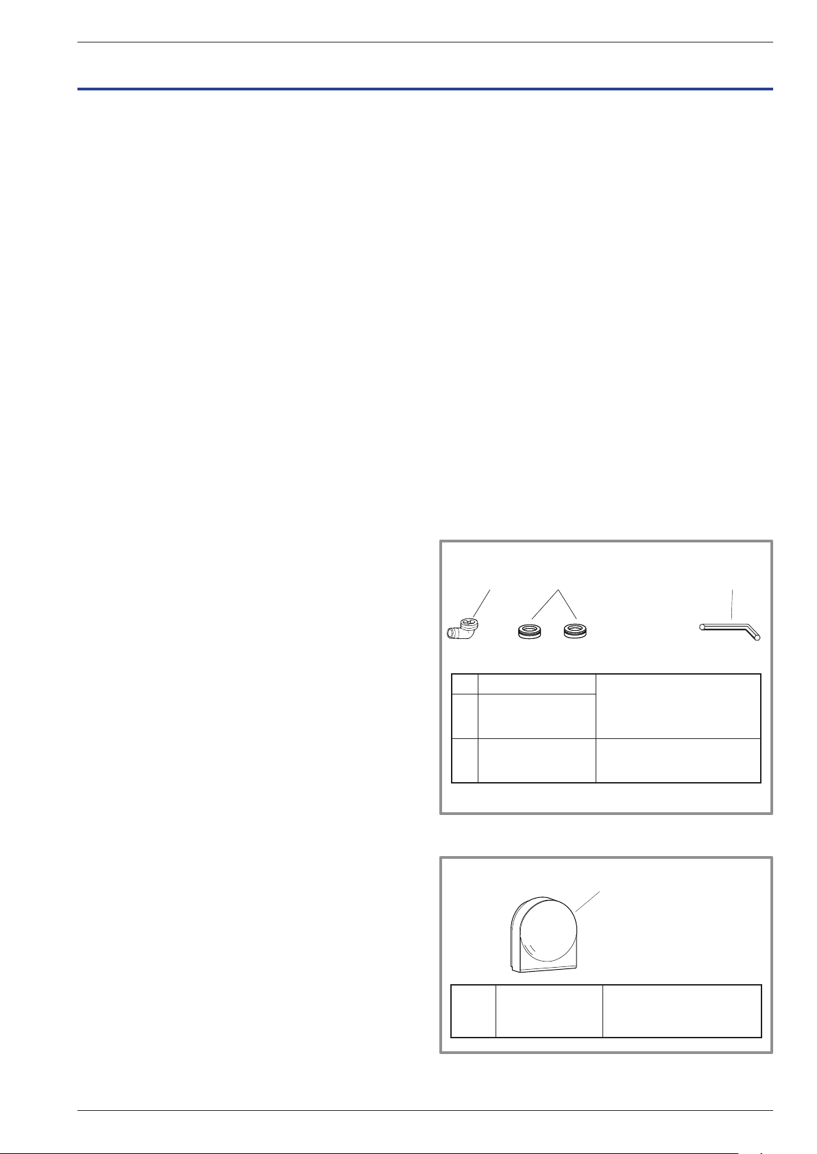
2.3.3 Accessories supplied
2
1
1
1 Elbow
Plugs (x2)
2
(depending on
model)
3 Allen key to open the valves
gure 12 - Accessories supplied with the external unit
2
for the evacuation of the
condensates
3
5
6
3
4
5 Outdoor sensor
gure 13 - Accessories supplied with
the hydraulic module
Installation and operating manual "1605 - EN" - 13 -
To monitor the outdoor
temp

alfea hybrid duo heat pump oil low NOx CH
2.3.4 Containment of refrigerant circuits
All refrigerant circuits fear contamination from dust and
moisture. If such pollutants introduced into refrigeration
circuit, they can contribute to degrade the reliability of
the heat pump.
" It’s necessary to ensure correct containment
connections and refrigerant circuits (hydraulic
unit, outdoor unit).
" In case of subsequent failure and expertise, the
nding of the presence of moisture or foreign
objects into the compressor oil would lead to
systematic exclusion of warranty.
- Check upon receipt that the ttings and the refrigeration
circuit caps mounted on hydraulic unit and outdoor unit
are properly seated and locked (impossible to loosen
bare hands). If this’s not the case, tighten them using
an against wrench.
- Check also that the refrigerant connections are
sealed (plastic caps or tubes crushed at the ends
and soldered). If the caps must be removed during
installation (tubes cut by example), put back them as
soon as possible.
2.4 Positioning
The choice of the position is particularly important
as having to move it later is a delicate operation that
requires a qualied person.
Choose the position of the outdoor unit and the hydraulic
module after discussion with the client.
Respect the max. and min. distances between the
Hydraulic module and the outdoor unit (gure 21, page
20), the performances and life of the system depend
on this.
2.5 Installation the outdoor unit
2.5.1 Installation precautions
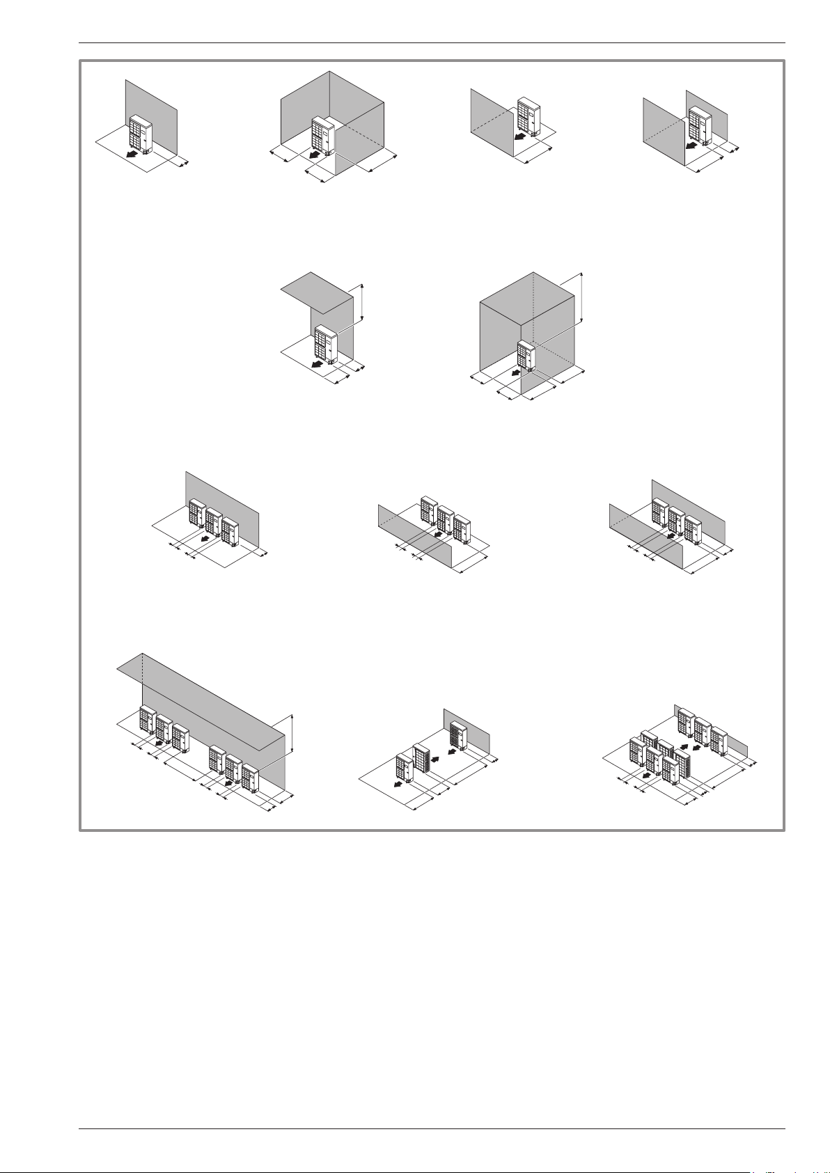
" The outdoor unit must only be installed
outdoors. If a shelter is requried, it must have
large openings on all 4 sides and respect the
installation clearances (gure 14).
• Prefer a sunny position sheltered from strong and
cold dominant winds (mistral, tramontane, etc...).
• the appliance must be fully accessible for the
installation and later maintenance work (gure 14).
• Ensure that the connections can be made easily with
the hydraulic module.
• The outdoor unit can be exposed to the weather,
however avoid installing it in places where it will
become dirty or have excessive water dripping onto it
(under a leaky drainpipe for example).
• When operating water may escape from the outdoor
unit. Do not install the appliance on a terrace,
prefer a drained spot (bed of gravel or sand).
If the installation is in an area where the temperature
can be lower than 0°C for a long period, check that the
presence of ice does not present any danger. It is also
possible to connect a drain pipe to the outdoor unit
(see gure 15, page 16).
• No obstacles must block the air circulation through the
evaporator and from the fan.
• Keep the outdoor unit away from sources of heat or
inammable products.
• Ensure that the appliance does not disturb neighbours
or users (sound levels, draughts caused, low
temperature of the air blown out with the risk of freezing
plants in its path).
• The surface on which the outdoor unit is tted must:
- be permeable (earth, gravel bed...),
- be easily capable of supporting its weight,
- allow solid attachment,
- not transmit any vibrations to the home (anti-vibration
pins are available among the accessories).
• The wall bracket can not be used in conditions likely to
transmit vibrations, ground position is preferred.
- 14 -
Installation and operating manual "1605 - EN"
alfea hybrid duo heat pump oil low NOx CH
250
250
or more
150
200
300
200
1000
300
Max. 500
250
250
or more
300
250
1500
or more
250
1000
or more
Max. 500
500
1500
250
250
or more
1000
or more
1500
or more
150
500
250
250
or more
1500
150
1500
250
250
or more
500
Max.300
1000
600
2000
or more
250
250
or more
gure 14 - Minimum clearances for the installation around the outdoor unit (all models)
1500
600
3000
or more
600
Installation and operating manual "1605 - EN" - 15 -
alfea hybrid duo heat pump oil low NOx CH
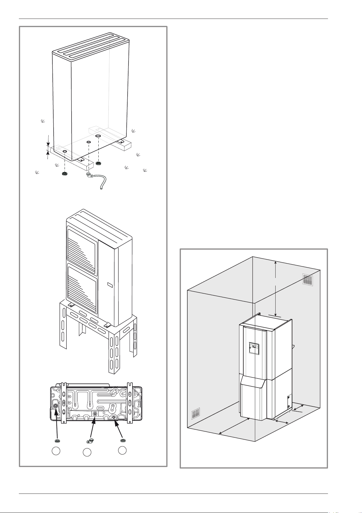
2.5.2 Fitting the outdoor unit
The outdoor unit must be raised by at least 50 mm
from the ground. In snowy regions, this height must be
increased but must not exceed 1.5 m.
- Attach the outdoor unit using screw and spring or split
washers to ensure they do not come loose.
2.5.3 Connecting the condensates drain
If an evacuation pipe must be used:
- Use the elbow provided (C) and connect a exible
hose diameter 16 mm to drain off the condensates.
- Use the Plug(s) provided (B) to block the condensate
tray orice.
Fit so that gravity ow of the condensates is ensured
(waste water, rainwater, gravel bed).
" If it is installed in a region where the temperature
can drop below 0 °C for long periods, t a
tracing resistor to the drain pipe to avoid it
freezing up. The resistance trace must heat not
just the evacuation pipe but also the bottom of
the condensate drip tray of the appliance.
* In regions where there is often snow,
(H) must be higher than the average thickness of snow.
2.6 Installation of the Hydraulic module
2.6.1 Requirements to installation space
The room where the appliance operates must respect
the regulations in force.
The appliance must be installed in a suitable and well
ventilated room. The room must have a new air inlet (A)
300 mm
B
- 16 -
B
gure 15 - Fit the outdoor unit,
evacuation of the condensates
C
B
minimum
150 mm*
A
1000mm
*If the refrigerating connections need to be passed
behind the appliance.
gure 16 - Minimum clearances for the installation
around the Hydraulic module
Installation and operating manual "1605 - EN"
500mm
alfea hybrid duo heat pump oil low NOx CH
with a free cross section that cannot be obstructed of at
least 50 cm2 that opens onto the lower part and a used
air outlet (B) with a free cross section that cannot be
obstructed of at least 100 cm2 positioned on the upper
part and opening directly outdoors (see gure 16).
Refer to Departmental sanitary Regulations Type
(RSD), article 53.4 .
The atmospheric conditions in the room must not be
humid; humidity is damaging for electrical appliances.
If the ground is humid or soft, use a base of sufcient
height.
To facilitate the servicing operations and permit access
to the various parts, it is recommended that sufcient
space be left all around the hydraulic module.
" The warranty on the heater will not cover any
installation of the appliance in a chlorine rich
atmosphere (hairdressers, launderette, etc.) or
any other corrosive vapours.
This equipment may not be installed in a bathroom or a
shower room.
Be careful of the presence of inammable gas close
to the heat pump when it is installed, especially when
brazing is required. The appliances are not antiexplosion
and must therefore not be installed in an explosive
atmosphere.
- To avoid any condensation inside the condensor only
remove the refrigerating circuit plugs when making
refrigerating connections.
- If the refrigerant connection only occurs at the end of
the installation, be sure that the refrigerant circuit caps*
remain in place and tight throughout the installation
duration.
* (Hydraulic module side and outdoor unit side)
- After the work is carried out each time on the
refrigerating circuit, and before nal connection, ret
the Plugs to avoid any pollution of the refrigerating
circuit (sealing with adhesive is not allowed).
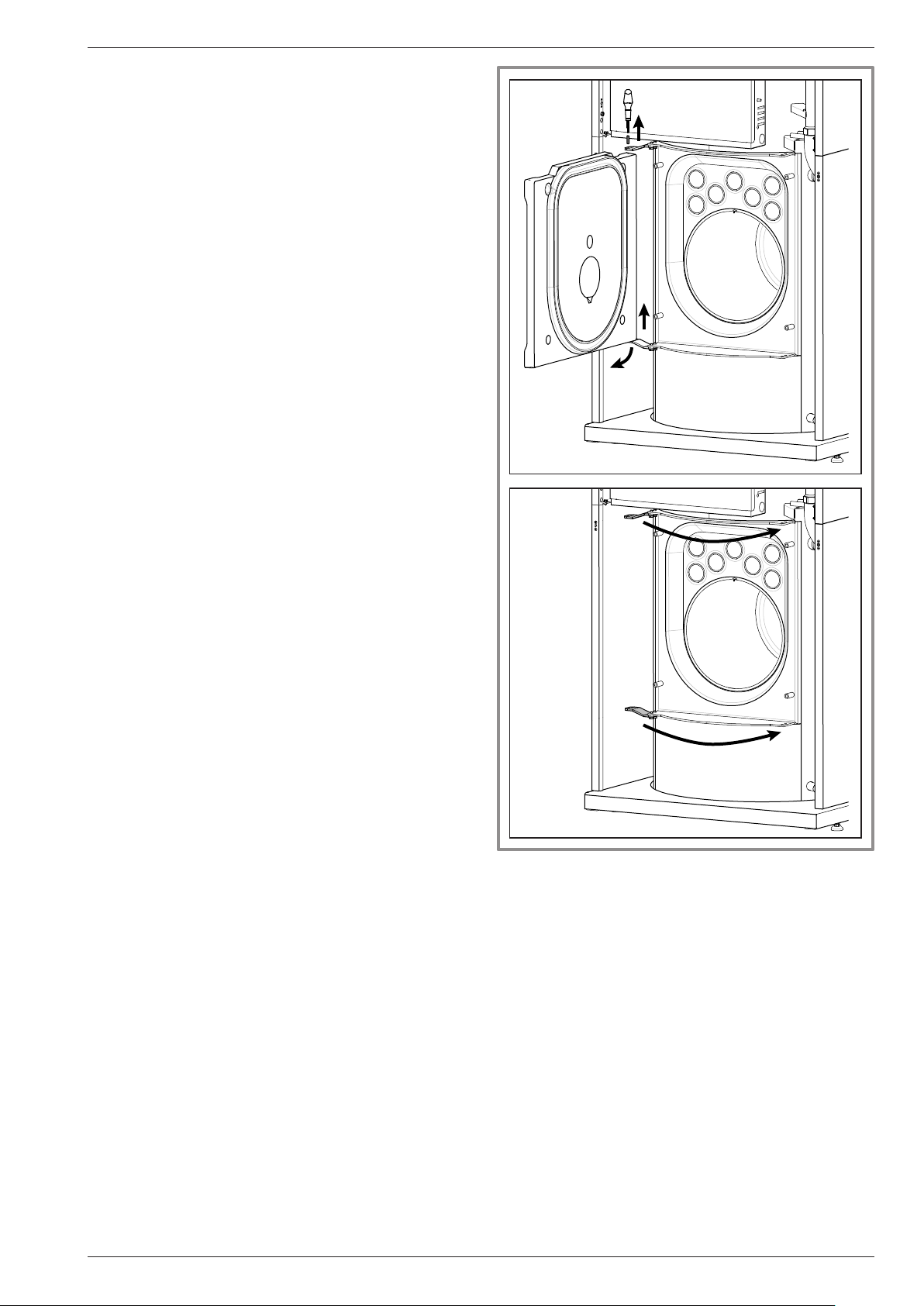
2.6.2 Reversible chamber door
The chamber door is tted with the hinges on the left
as standard. For it to open in the opposite direction,
change over the side on which the hinges and pins are
tted.
- Remove the burner.
- Remove the chamber door.
Remove the 4 door attachment screws.
Remove the upper pin.
- Raise and tilt the door.
" Do not hold the door by its thermal protection.
-- Remove the hinges and x them on the other
side.
- Remove the lower pin and position it on the RH side
of the door.
- Ret the chamber door and attach the upper pin.
" Lightly tighten the screws of the closing door.
gure 17 - Reversible chamber door
2.6.3 Evacuation pipe
(see gure 18, page 18)
The evacuation pipe must comply with the regulations
in force.
The evacuation pipe must have suitable dimensions.
Minimum cross section required = 2.5 dm2 for a chimney
of between 5 and 20 m in height, or a ball valve of 16
cm or Ø 18 cm.
The pipe must only be connected to a single appliance.
The pipe must be waterproof.
The pipe must be correctly thermally insulated in order
to avoid any problems of condensation; otherwise the
pipe must have a tube tted with a system for collecting
the condensates.
Use a good quality watertight tube that is compatible
with the fuel used, possibly with a system for collecting
the condensates.
Installation and operating manual "1605 - EN" - 17 -

alfea hybrid duo heat pump oil low NOx CH
40 cm
1,2 m
40 cm
8m
gure 18 - Height of the base
of the evacuation ue (B23)
8m
2.7 Refrigerating connections
40 cm
< 15°
2.6.4 Connection pipe
The evacuation pipe must comply with the regulations
in force.
The cross section of the connection pipe must not be
smaller than the outlet nozzle of the appliance.
The connection pipe must be removable.
It is strongly recommended to t a ue regulator to the
pipe when the low pressure of the chimney is greater
than 30 Pa. The ue gas case is reversible (2 screws)
and the smoke outlet axis may be offset with respect to
the axis of the boiler to the right or to the left.
The evacuation nozzle is to be connected to the pipe so
that there are no leaks.
" This appliance uses the refrigerating uid
R410A.
Respect the legislation for handling refrigerating uids.
2.7.1 Rules and precautions
• After each operation on the refrigerating circuit, and
before the nal connection, ensure that the plugs are
tted so as to avoid any pollution of the refrigerating
circuit.
• Minimum tooling required
- Set of pressure gauges (Manifold) with exible hoses
for HFC (Hydrouorocarbons).
- Vacuum gauge with isolation valves.
- Special vacuum pump for HFC (use of a classic
vacuum pump only allowed if tted with a non return
valve for the suction).
- Disengageable aring tool, tube cutter, deburrer,
wrenches,
- Approved refrigerating uid detector (sensitivity 5g/
an).
" Tooling that has been in contact with HCFC (R22
for example) or CFC may not be used.
• The manufacturer refuses all responsibility for
warranty if the above values are not respected.
• Tube expanders (ared connectors)
" Lubrication with mineral oil
(for R12, R22) is prohibited.
- Only lubricate with polyolester refrigerating oil (POE).
If POE oil is not available, t without oil.
• Brazing on the refrigerating circuit
(if required)
- Silver brazing (40% minimum recommended).
- Brazing with a dry Nitrogen stream only.
• To eliminate the swarf from the pipes, use dryNitrogen to
avoid introducing humidity that can harm the operation
of the appliance. In general, take every precaution to
avoid humidity penetrating into the appliance.
• Thermally insulate the gas and liquid pipe to avoid
all condensation. Use insulating sleeves that resist
temperatures of over 90°C. In addition, if the level
of humidity where the refrigerating pipes risks
exceeding 70%, protect them with insulating sleeves.
Use a 15 mm thicker sleeve if the humidity reaches
80%, and a 20 mm thicker sleeve if the humidity
exceeds 80%. If the recommended thicknesses are
not respected in the conditions described above,
condensation will form on the surface of the insulation.
Finally, ensure that insulating sleeves are used that
have a thermal conductivity equal to 0.045 W/mK or
lower when the temperature is equal to 20°C. The
insulation must be impermeable to resist the steam
passing during the defrosting cycles (glass wool is
prohibited).
- 18 -
Cover the ared surface
with POE refrigerating oil.
Do not use mineral oil.
Installation and operating manual "1605 - EN"
alfea hybrid duo heat pump oil low NOx CH
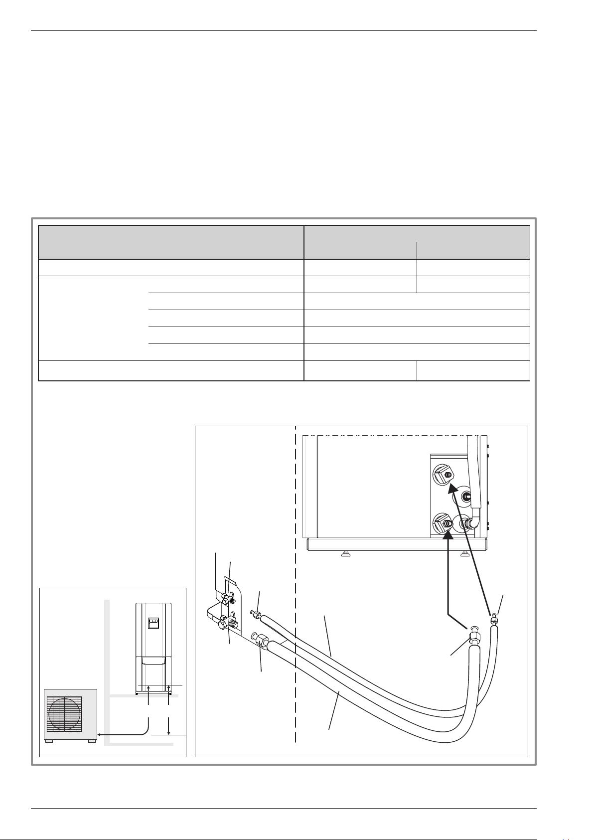
2.7.2 Refrigerating connections
The connection between the outdoor unit and the
Hydraulic module must only be made with new copper
connectors (refrigerating quality) and individually
insulated.
Respect the diameters of the pipes and the authorised
lengths(gure 21, page 20).
If the refrigeration connections are exposed to
weathering or UV- and the insulation is not strong, it is
necessary to provide protection.
Handle the pipes and pass them through the walls with
the protection plugs in place.
If the distance between the outdoor unit and the
hydraulic unit exceeds the length of the maximum
conduits indicated in the table, an additional charge of
R410A must be loaded.
The quantity of R410A added must be suited to the
length of the refrigerating circuit so as to maintain the
performances of the heat pump and not damage the
compressor (gure 21, page 20).
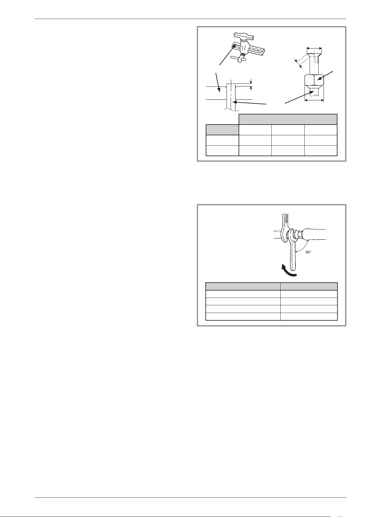
2.7.3 Flaring
- Cut the tube with a tube cutter to the required length
without deforming it.
- Carefully deburr while holding the tube downwards to
avoid introducing swarf into the tube.
- Remove the are nut from the connector on the valve
to be connected and t the tube into the nut.
- Flare it leaving the tube protruding fro the expandable
aring tool.
- After aring, check the condition of the journal (L).
It must not be scratched or signs of splitting. Also
check the side (B).
B
Expander
tube
pipe
Dimensions in mm
ø pipe L B 0/
9.52 (3/8") 2.5 to 2.7 13.2 22
15.88 (5/8") 2.9 to 3.1 19.7 29
gure 19 - Flared section for are connectors
L
C
-0,4
Spanner
Torque wrench
Flare
nut
C
2.7.4 Forming the refrigerant tubes
The refrigerating tubes must only be formed using a
bending machine or a bending spring in order to avoid
any risks of crushing or splitting.
" Warning!
• Remove the insulation locally to bend the tubes.
• Do not bend the copper to an angle of more than 90°.
• Do not bend the tubes more than 3 times at the same
position otherwise this can cause the pipe to split
(hardening of the metal).
Designation Tightening torque
Flare nut 9,52 mm (3/8") 33 to 42 Nm
Flare nut 15,88 mm (5/8") 63 to 77 Nm
Plug (A) 5/8" 30 to 35 Nm
Plug (B) 3/8", 5/8" 10 to 12 Nm
gure 20 - Tightening torques
Installation and operating manual "1605 - EN" - 19 -
alfea hybrid duo heat pump oil low NOx CH
2.7.5 Connecting the are connections
" The connections must be made the day the gas
is connected to the installation (see § 2.8, page
21).
" Pay special attention to the position of the tube
aligned with its connector to avoid damaging
the thread. A correctly aligned connector can be
tted easily by hand without much force being
- Remove the plugs from the pipes and refrigerating
connections
- Place the tube in front of the are connector and
screw on the nut by hand, holding the connector with a
spanner, until contact is made.
- Respect the tightening torques stated (see gure 20,
page 19).
required.
" The refrigerating circuit is very sensitive to dust
and humidity, check that the zone around the
connection is dry and clean before removing the
plugs that protect the refrigerating connectors.
PAC Model alféa hybrid duo oil single phase and three phase
Gas Liquid
Outdoor unit connectors 5/8" 3/8"
Diameter (D1) 5/8" (D2) 3/8"
Minimum length (L) 5
Refrigerating
connections
Maximum * length (L) 15
Maximum * length (L) 20
Maximum ** height difference (D) 20
Hydraulic module connectors 5/8" 3/8"
*: without additional volume of R410A
**: take into account any additional volume (see § 2.8.3, page 22)
Outdoor
unit
Liquid
valve
Flare
nut
“Liquid” refrigeration connection
diameter D2
Gas
valve
Flare
nut
Hydraulic
unit
Flare
nut
Flare
nut
- 20 -
DL
“Gas” refrigeration connection
diameter D1
gure 21 - connection of thre refrigerating connectors (authorised diameters and lengths - in metres)
Installation and operating manual "1605 - EN"

alfea hybrid duo heat pump oil low NOx CH
2.8 Commissioning
the refrigerating gas installation
" This operation is only to be carried out by
qualied tters in compliance with the legislation
for the handling of refrigerating uids.
" Evacuation with a calibrated vacuum pump is
essential (see appendix 1).
" Do not use equipment that has previously been
used with a refrigerating uid other than a HFC.
" Remove the refrigerant circuit caps only when
building the refrigerant connections.
" Unfavourable conditions:
- If the temperature outdoors is between +5 and
+10°C, a vacuum gauge must be used to check
the evacuation and use the 3 vacuum method.
(see appendix 2).
- If the temperature outdoors is below +5°C, it is
strongly recommended to connect the gas.
APPENDIX 1
Method for calibration and control of a vacuum
pump
- Check the oil level of the vacuum pump.
- Connect the vacuum pump with the vacuum gauge
according to the scheme.
Vacuum
Vacuomètre
Flexible
Outlet
bouché
hose
- Empty for 3 minutes
- After 3 minutes, the pump
reaches its threshold value and the vacuum gauge
needle does not move.
- Compare the obtained pressure with the value
of the table. Depending on the temperature, this
pressure must be less than the value indicated in
the table.
=> If this is not the case, change the seal, the
exible hose or the pump.
T °C 5°C<T<10°C 10°C<T<15°C 15°C < T
Pmax
- bar . .
- mbar
. . . 0.009 . . .
. . . . . 9 . . . . .
. . . 0.015 . . .
. . . . 15 . . . .
2.8.1 Start procedure
gauge
Vacuum
Pompe
pump
à vide
. . . 0.020 . . .
. . . .20 . . . . .
APPENDIX 2
Method 3 empty
- Connect the high pressure exible of the manifold
on the load orice (gas connection). A valve must
be mounted on the exible hose from the vacuum
pump in order to isolate it.
a) Empty up to the desired value (see table appendix
1),
Jeu de manomètres
Set of pressure gauges
pressure
Low
Basse
pression
(manifold)
(manifold)
Lo
Hi
High
Haute
pressure
pression
Connection...
UE
liquid
Gas
Liaison...
liquide
gaz
MH
Vacuum gauge
Vacuomètre
Vacuum pump
Pompe à vide
b) Switch off the vacuum pump, close the valve at
the end of the service hose (yellow), Connect this
hose to the pressure regulator of the Nitrogen bottle,
inject 2 bars, close the hose valve,
Nitrogen
Lo
High
Hi
Haute
pressure
pression
UE
Connection...
Liaison...
liquid
liquide
gaz
Gas
MH
Azote
c) Connect the exible hose again to the vacuum
pump, switch it on and progressively open the
exible valve hose.
Lo
High
Hi
Haute
pressure
pression
Connection...
UE
liquid
Liaison...
liquide
gaz
Gas
MH
d) Repeat this operation at least three times.
" Reminder: it is strictly prohibited to carry out
these operations with refrigerating uid.
• Checks before connection:
Checking the gas connection (large diameter).
- Connect the "Gas" connection to the outdoor unit.
- Blow dry nitrogen into the "Gas" connection and
observe this end:
If water or impurities come out, use a new refrigerating
connection.
Otherwise expand and immediately connect to the
Hydraulic module.
Installation and operating manual "1605 - EN" - 21 -
Checking the liquid connection (small diameter).
- Connect the "Liquid" connection to the hydraulic unit.
- Blast with Nitrogen the entire gas-condensor-liquid
connection and observe the end (outdoor unit side).
If water or impurities come out, use a new refrigerating
connection.
Otherwise expand and immediately connect to the
outdoor unit.
 Loading...