

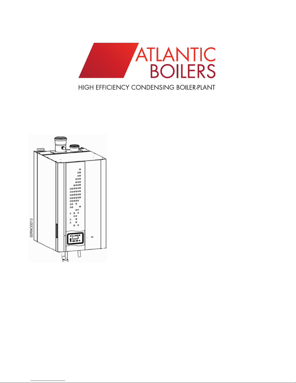
Atlantic VF 40, VF 60, VF 80, VF 100 Use & Maintenance Manual
ADDRESS: ATLANTIC BOILERS, PO BOX 11, ASHTON UNDER LYNE, OL6 7TR
WEB: WWW.ATLANTICBOILERS.COM EMAIL: INFO@ATLANTICBOILERS.COM
TEL: 0161 621 5960 FAX: 0161 621 5966
VF Model
USE & MAINTENANCE
WALL-MOUNTED GAS CONDENSING BOILER
40, 60, 80 & 100KW OUTPUT
MODULATING BURNERS
After sales service is guaranteed by Atlantic Boilers
The boilers conform to the following CE Directives
Directive 2006/95/CD - low voltage
Directive 2004/108/CEE - electromagnetic compatibility
Directive 92/42/CEE - efficiency
Directive 90/396/CEE - gas fired equipment

Summary
1. General characteristics .........................................................................................................3
1.1. Acceptable gas pressure .................................................................................................................3
1.2. Combustion conditions .....................................................................................................................3
1.3. Operating conditions .......................................................................................................................4
1.4. Electrical conditions .........................................................................................................................4
2. Boiler installation ...................................................................................................................5
3. Running the boiler .................................................................................................................5
4. Switching the boiler off..........................................................................................................5
5. Maintenance of the boiler......................................................................................................5
6. Frost protection......................................................................................................................5
7. Boiler control panel................................................................................................................6
7.1. Control panel fascia..........................................................................................................................6
7.2. Control panel display arrangement...................................................................................................6
7.3. Control panel functions.....................................................................................................................7
7.4. Adjustment of the settings.................................................................................................................9
7.5. Information on boiler condition........................................................................................................10
7.6. Adjust the settings...........................................................................................................................13
8. Function of the LMU64 060D168..........................................................................................14
9. Table of boiler settings for the Client..................................................................................15
page 3/17
1. General Characteristics
The V F boiler is set in the Factory to operate
on Natural Gas Group H with a supply pressure of 20mBar.
F
or higher gas pressure up to 300mBar, a filter and
a pressure regulator must precede the V
F gas valve.
1.1. Acceptable gas pressure
Gaz naturel H
G20
Nominal (mbar)
20
Minimum (mbar)
17
Maximum (mbar)
25
1.2. Combustion conditions
VF
40 60 80 100
Nominal output Pn (80/60°C)
kW
56,5
92,6
Nominal condensing output P (50/30°C)
kW
61,8 100
Nominal heat outflow Qn
kW
58 95,1
Minimum heat outflow Qmin
kW
14,5 25,5
G20 gas flow rate at Pn
m
3
/h 6,1 10,1
Recommended CO2 values
% see chapter 6.2
Mass flow of flue gases Qn / Qmin (80/60°C)
g/s 27 / 6,1 44 / 12
Mass flow of flue gases Qn / Qmin (50/30°C)
g/s 25,3 / 5,7 39,6 / 10,4
Temperature of flue gases Qn / Qmin (80/60°C)
°C 70 / 55 76 / 60
Temperature of flue gases Qn / Qmin (50/30°C)
°C 46 / 32 56 / 32
Pressure loss for flue gas circuit Qn
Pa 75 74
Diameter of flue gas outlet mm 80 100
Maximum pressure at flue gas output (B23P)
Qn / Qmin (80/60°C) *
Pa 150 / 8 110 / 6
Maximum pressure at flue gas outlet (B23P)
Qn / Qmin (50/30°C) *
Pa 123 / 3 97 / 5
Combustion air at Qn
m
3
/h 76 124
NOx class to EN 483:2000 4 / 5 5 / 5
Types of flue gas and combustion air arrangements
B23, B23P, C13, C33, C53

page 4/17
1.3. Operating conditions
VF
60 100
Maximum flow water temperature °C 80
Temperature Limit thermostat °C 100
Maximum working pressure
hPa
(bar)
4000
(4,0)
Minimum working pressure
hPa
(bar)
1000
(1,0)
Minimum water flow rate :
primary / secondary circuits (P/20)
l/s 0.67 / 0.67 1.11 / 1.11
Water content
l 6,1 9,4
Dry weight
kg 73 88
1.4. Electrical conditions
VF
60 100
Electrical supply
V 230 V AC (+10% -15%), 50Hz
Requirement at Qn
W 190 300
Requirement at standing load
W 7
Maximum length for sensor cables
m
domestic hot watersensor : 10
external sensor : 40
room thermostat : 40
room sensor : 50
Control panel requirement
V
A
230V AC (+10%, -15%)
5 mA à 1 A
Temperature °C
Ohm resistance
flow/return sensor QAK36.095/109
flue gas sensor QAK36.670/109
NTC 10 KΩ at 25°C
0°C
32 555 Ω
10°C
19 873 Ω
20°C
12 488 Ω
25°C
10 000 Ω
30°C
8 059 Ω
40°C
5 330 Ω
50°C
3 605 Ω
60°C
2 490 Ω
70°C
1 753 Ω
80°C
1 256 Ω
90°C
915 Ω
100°C
677 Ω
110°C
508 Ω
120°C
387 Ω
page 5/17
2. Boiler installation
Installation and maintenance of the installation shoukd be carried by a qualified
engineer according to the recommendations of the relevant codes of practice
and of the boiler manufacturer
The boiler must be installed in an appropriately ventilated compartment
…………………………………………………………….
3. Running the boiler
The boiler must be supplied with G20 natural gas
to bring the boiler into service
1. switch on the electrical supply
2. use the controls to set up a heating demand
3. when the boiler fires, check the gas line for soundness
and measure the combustion efficiency using
a flue gas analyser
4. Set up the controls to the programme required
by the Client
breaking any Factory equipment seals
invalidates the Boiler guarantee
4. Switching the boiler off
1. switch off the electricity supply
2. close the gas supply
5. Maintenance of the boiler
It is essential to service the boiler every year
Be ensure to employ a qualified engineer
6. Frost protection
If the boiler plant is not in use and there
is a risk of freezing, then anti-freeze should be
introduced to the system
In addition the boiler can be drained as follows
• switch off the electricity supply
• close the gas supply valve
• close the heating system isolating valve
• use the safety valve to release water pressure in the boiler
• release the automatic air vent to allow air to enter the boiler
• open the boiler drain valve to release
water from the boiler
page 6/17
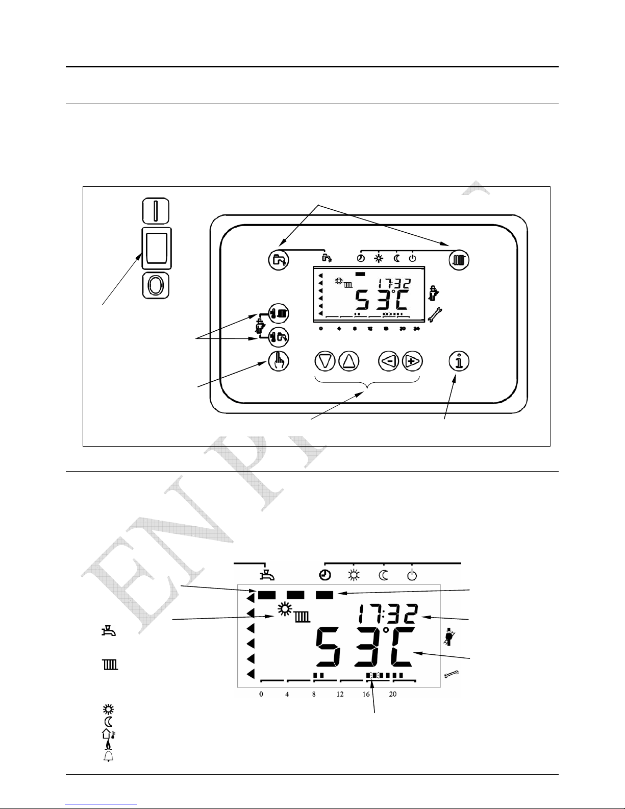
7. Boiler Control Panel
7.1. Control panel fascia
7.2. Display
The screen supplies boiler function, time, hourly programme,
temperature, burner, condition and defect
Hourly programme
Space heating
requirement
Time
Boiler
temperature
DHW requirement
Symbols :
DHW in progress
Space heating
in progress
Comfort requirement
Set back requirement
Outside temperature
Flame established
Defect
Touch requirement
Touch programme Touch information
boiIer isolator
Touch
signals
Touch
re-set
 Loading...