

Page 1
PUMP PROTECTOR
Operating Manual
1-877-80-PONDS
www.atlanticwatergardens.com
Page 2
Product: Pump Protector
Model: TWPP14
Features:
• Pump motor is protected from operating when system is dry
• Provides pump protection from certain cavitations due to
decreased water ow
• Protection from excessive line currents
• 14 amp / 1HP maximum at 120 VAC operation
• Reset/calibration push button for fast commissioning
• Works with existing ground fault circuits
• No wiring; just plug in the unit and pump
Description:
The Pump Protector is an electronic control module designed to help protect pump
motor damage due to sudden restriction in water ow or when system is dry. The
product monitors subtle line power changes that are created by the pump during
changing load conditions, and therefore does not need level
sensors which can plug during operation.
When line current changes exceed the product’s internal threshold, the power to the
pump is switched off until the user pushes the reset button. The product also has
calibration means to set the lower and upper current threshold specic to each pump
size to protect during abnormal power changes.
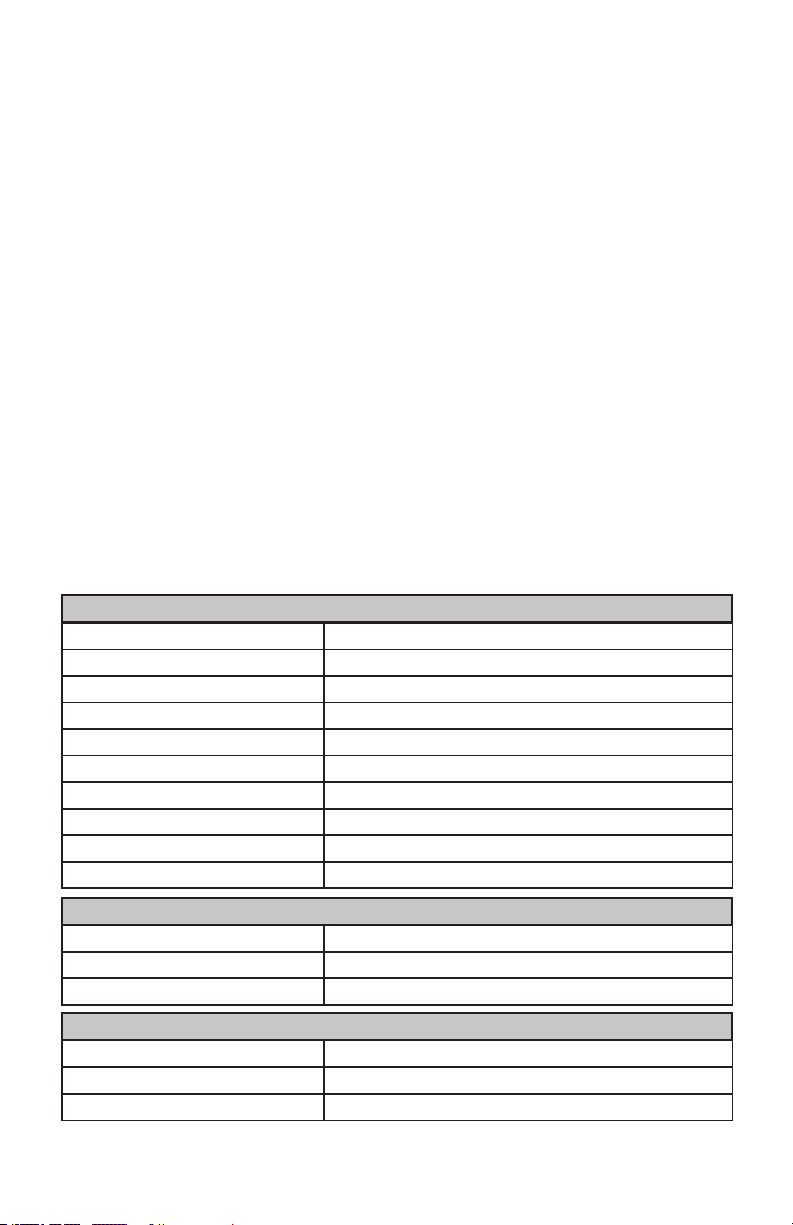
ELECTRICAL
Supply Voltage 105-132 AC
Supply Voltage Frequency 50Hz, 60Hz
Burden Current <12mA
Output Type Relay Form A
Output Current (Maximum) 14 Amp AC, 1 HP
Over Current Circuit Protection 125% of Programmed Current, < 10 sec response time
Under Current Circuit Protection 75% of Programmed Current, <10 sec response time
Overload Current Protection 15 amp +/- 20%, <10 AC cycles
Cavitations Current Protection Adaptive, <10 sec response
Pump Dry Shut down < 10 seconds
ENVIRONMENTAL
Sealing IP64, Dust protection and water spray
Shock 10G
Temperature -25° to 50°C
MECHANICAL
Package Material ASA, Black
Dimensions (LxWxD) L 5.18”, Q 3.25”, H 2.12” w/o base plate
Mounting Holes 2 x 0.125”
2
Page 3
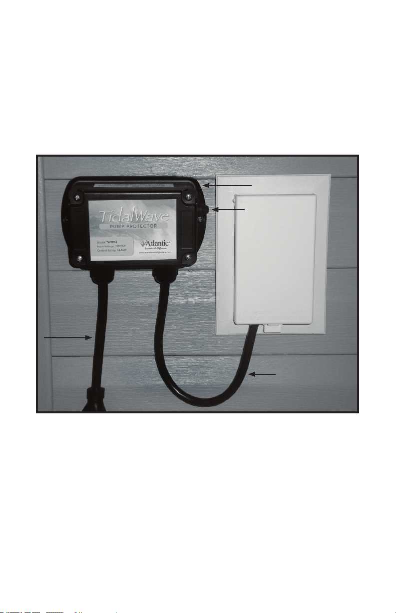
Installation Instructions:
1. Attach the mounting plate to the back of the Pump Protector with
the four screws provided.
2. Choose a spot near the GFCI outlet to mount the Pump Protector.
3. Attach the Pump Protector to a post or structure using two exterior
screws (not included).
Note: Make sure that the Pump Protector is high enough that the Pump Power Supply
Cord ( gure 1) is not lying on the ground. The Pump Protector can either be mounted
horizontally or vertically.
Controller Unit
Reset Button
Pump Power
Supply Cord
Controller Unit
Power Supply Cord
FIGURE 1
To Improve The Reliability of Your Pump Protecting System:
1. Provide adequate wiring to the Pump Protector to ensure that load
switching from other appliances do not change line voltatge more
than 10% during abrupt load changes.
2. Calibrate the Pump Protector only after verication that the pump
liquid ow is adequate.
3. Connect only one pump to the Pump Protector.
4. Regularly check the conveyance system for slow build up of
deposits that can affect water ow over time.
5. Some pumps inherently have cavitation due to pump design and
may intermittently shut down.
Page 4

Instructions - Quick Set Up:
1. Connect pump motor to the pump power supply cord. (See gure 1.)
2. Plug the controller power supply cord into GFCI protected outlet. The pump
should start and buzzer will sound. (See gure 1.)
3. Ensure water ow is adequate in the conveyance lines and wait until the
buzzer stops.
4. Press the reset button once – the internal buzzer will pulse.
5. During the time between buzzer pulse 2 and pulse 5, press the reset button
once – this auto calibrates the unit to a power change range of plus or minus
10%. These settings will be permanently stored.
NOTE: Some pumps require a wider power change. Push the reset button
twice for a range of plus or minus 15%.
6. The buzzer will increase in tone frequency to acknowledge button depression.
7. The above process can be repeated if pump is changed or operating
conditions change.
Application Summary
The Pump Protector is designed to help reduce damage to water pumps like
those used in outdoor ponds and pond-free water features. Pumps need water
owing through the chamber in order to cool the motor windings. If water ow
is impeded, the pump can overheat, resulting in permanent damage. Water also
lubricates moving parts and therefore a loss of water ow can also damage these
internal parts.
Excessive water bubbles or a quick reduction in water ow creates small
changes in the line current to the pump. Additionally, a blockage from debris on
either the inlet or outlet side also causes small line current changes. The Pump
Protector control module is designed to detect these small changes and take action to help protect the pump. Upon fault detection the control circuit will switch
off the power to the pump to protect it from over heating. Once tripped, the
user needs to inspect the water system to ensure adequate water ow is
established to the pump. Pressing the reset button on the control module once
will restart the pump.
The Pump Protector also has a calibration feature, which sets a high and low
protection threshold for each pump. To implement this feature, press the reset
button once and the buzzer will beep. Then press the button once between the
second and fth beep from the buzzer. The unit will acknowledge by increasing
the tone of the buzzer. The control module is now calibrated to your pump. It is
critical that the water ow is checked for adequate movement before calibrating
the system to ensure that trip thresholds are set to normal operating conditions.
Some motors have thermal protection built in to help protect the pump. The
thermal protection will turn off the pump when hot but after cooling the pump
will automatically restart. Therefore the pump can get into a continuous on-off
cycle, which can result in permanent pump damage. The control circuit will detect
a thermal shutdown as a low current fault and switch off the pump to
eliminate cycling.
4
 Loading...