


Controller
Indicator
Transmitter
1/32 DIN - 48 x 24
C10 line c
U s e r m a n u a l • M . I . U . C 1 0 - 1 / 0 2 . 0 6 • C o d . J 3 0 - 4 7 8 - 1 A C 1 S E A
C UL US
LISTED
ATHENA CONTROLS, INC.
5145 Campus Drive
Plymouth Meeting
PA 19462 U.S.A.
Tel: (610) 828-2490
Fax: (610) 828-7084
AthenaControls.com
Controller
Indicator
Transmitter
1/32 DIN - 48 x 24
C10 line |
c |
|
|
|
C U US |
|
L |
|
LISTED |
 274.8
274.8
information
c
NOTES
ON ELECTRIC
SAFETY AND
ELECTROMAGNETIC COMPATIBILITY.
2
Please, read carefully these instructions before proceeding with the installation of the controller.
Class II instrument, rear panel mounting.
This controller has been designed with compliance to:
Regulations on electrical apparatus (appliance, systems and installations) according to the European Community directive 73/23 CEE amended by the European Comunity directive 93/68 CEE and the Regulations on the essential protection requirements in electrical apparatus EN 61010- 1 (IEC 1010 - 1) : 90 +A1:92 + A2:95.
Regulations on Electromagnetic Compatibility according to the European Community directive n089/336/CEE, amended by the European Community directive n° 92/31/CEE and the following regulations:
Regulations on RF emissions
EN50081 - 1 residential environments EN50081 - 2 for industrial environments Regulation on RF immunity
EN500082-2 for industrial equipment and system
It is important to understand that it’s responsibility of the installer to ensure the compliance of the regulations on safety requirements and EMC.
The device has no user serviceable parts and requires special equipment and specialised engineers. Therefore, a repair can be hardly carried on directly by the user. For this purpose, the manufacturer provides technical assistance and the repair service for its Customers.
Please, contact your nearest Agent for further information.
All the information and warnings about safety and electromagnetic compatibility are marked with the Bsign, at the side of the note.
|
|
Table of contents |
|
TABLE OF CONTENTS 1 |
INSTALLATION........................................................................................................................... |
Page |
4 |
2 |
ELECTRICAL CONNECTIONS..................................................................................... |
Page |
8 |
3 |
PRODUCT CODING.............................................................................................................. |
Page |
14 |
4 |
OPERATIONS.............................................................................................................................. |
Page |
18 |
5 |
AUTOMATIC TUNE............................................................................................................... |
Page |
28 |
6 |
TECHNICAL SPECIFICATIONS................................................................................... |
Page |
29 |
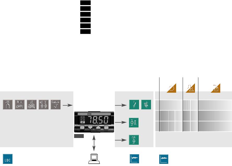
Resources |
|
Operating mode |
|
|
|
Control |
Alarms |
Retransmission |
|||||||
|
|
|
|
|
|
|
|
|
|
|
|
|
|
|
|
|
|
|
|
|
|
|
|
|
|
|
|
|
|
|
|
|
|
|
|
|
|
|
|
Main universal input |
OP1 |
|
|
|
|
PV |
PV |
0 |
Indication |
OP1 OP2 OP4 |
|||
|
|
only |
|
|||
|
|
1 |
Single |
OP1 |
|
OP2 OP4 |
|
OP2 |
output |
|
|||
|
|
2 |
Single |
OP2 OP1 |
OP4 |
|
|
|
output |
||||
C10 |
OP4 |
|
|
|
|
|
|
(option) |
|
|
|
|
|
Setpoint |
|
Fuzzy tuning with automatic selection |
|
|
||
|
Modbus RS485 |
|
|
|
|
|
|
Parameterisation |
One shot |
|
One shot |
|
|
|
Supervision |
Auto tuning |
|
Natural frequency |
||
3
1 - Installation
1 INSTALLATION
Installation must only be carried out by qualified personnel.
Before proceeding with the installation of this controller, follow the instructions illustrated in this manual and, particularly the installation precautions marked with the B symbol, related to the European Community directive on electrical protection and electromagnetic compatibility.
B
To prevent hands or metal touching parts that may be electrically live, the controllers must be installed in an enclosure and/or in a cubicle.
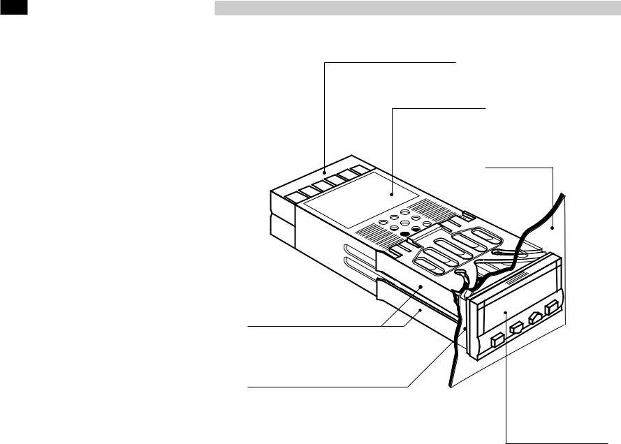
1.1 GENERAL DESCRIPTION
IP 20 Termination Unit
EN61010 - 1 (IEC1010 - 1)
Product code label
Panel surface
Mounting clamps
Sealin front panel gasket
Front panel
IP65 protection
EN 60529 (IEC 529)
4

1.2 DIMENSIONAL DETAILS
48mm
1.89in
25 mm
0.99 in
20 mm max
0.79 in max
120 mm
4.72 in
1 - Installation
1.3 PANEL CUT-OUT
|
|
|
|
|
|
|
|
|
|
65 mm min |
|
|||||||
|
|
|
|
|
2.56 |
in min |
|
|||||||||||
|
|
|
|
|
|
|
|
|
|
|
|
|
|
|
|
|
min. |
min. |
|
|
|
|
|
|
|
|
|
|
|
|
|
|
|
|
|
||
|
|
|
|
|
|
|
|
|
|
|
|
|
|
|
|
|
||
|
|
|
|
|
|
|
|
|
|
|
|
|
|
|
|
|
||
|
|
|
|
|
|
|
|
|
|
|
|
|
|
|
|
|
||
|
|
|
|
mm |
in |
|
|
|
|
|
|
|
42 mm |
1.65 in |
||||
|
22.2+0.3 |
0.87+0.01 |
|
|
|
|
|
|
|
|
|
|
|
|||||
|
|
|
|
|
|
|
|
|
|
|
|
|||||||
|
|
|
|
|
|
|
|
|||||||||||
|
|
|
|
|
|
|
|
|
|
|
|
|
|
|||||
|
|
|
|
|
|
|
|
|||||||||||
|
|
|
|
|
|
|
|
|
45+0.6 mm |
|
|
|
|
|
|
|
||
|
|
|
|
|
|
|
|
1.78+0.023 in |
|
|
|
|
|
|
|
|||
5

1 - Installation
1.4 ENVIRONMENTAL RATINGS
Operating conditions
B
M |
Altitude up to 2000 m |
|
|
|
|
T |
Temperature 0…50°C |
|
|
|
|
%Rh |
Relative humidity 5…95 % non-condensing |
|
|
|
|
|
|
|
Special conditions |
Suggestions |
|
|
|
|
M Altitude > 2000 m |
Use 24V~ supply version |
|
|
|
|
T |
Temperature >50°C |
Use forced air ventilation |
|
|
|
%Rh |
Humidity > 95 % |
Warm up |
|
|
|
P |
Conducting atmosphere |
Use filter |
|
|
|
|
|
|
Forbidden Conditions D |
|
|
|
|
|
C |
Corrosive atmosphere |
|
|
|
|
E |
Explosive atmosphere |
|
|
|
|
6

|
|
|
|
|
|
|
|
1 - Installation |
|
|
|
|
|
|
|
||
1.5 PANEL MOUNTING |
|
|
|
|
|
|
||
|
|
|
|
|
|
|
|
|
1.5.1 INSERT THE INSTRUMENT |
|
1.5.2 INSTALLATION SECURING |
|
|
1.5.3 CLAMPS REMOVING |
|||
1 |
Prepare panel cut-out |
1 |
Position the mounting clamps |
1 |
Insert the screwdriver in the clips |
|||
2 |
Check front panel gasket posi- |
2 |
Push the mounting clamps |
|
|
of the clamps |
||
|
tion |
|
towards the panel surface to |
2 |
Rotate the screwdriver |
|||
3 |
Insert the instrument through |
|
secure the instrument |
|
|
|
||
|
the cut-out |
|
|
|
|
|
|
|
1
1
3 |
2 |
|
1 |
||
1 |
|
|
1.5.4 INSTRUMENT UNPLUGGING |
|
|
1 Push and |
1 |
|
2 pull to remove the instrument |
||
Electrostatic discharges can dam- |
|
|
age the instrument |
|
|
Before removing the instrument the |
2 |
|
operator must discharge himself |
1 |
|
to ground |
||
|
B
1MΩ
7
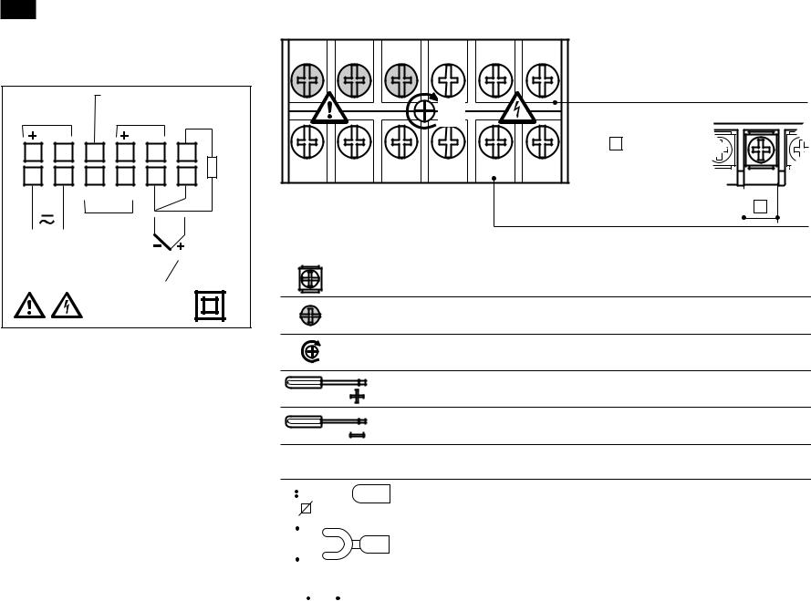
2 - Electrical connections
2 ELECTRICAL CONNECTIONS
RS485 |
+18V— OUT |
|||
OP2 - L |
||||
(OP4) |
||||
|
|
|
A |
|
|
|
|
||
7 |
8 |
9 |
10 |
11 |
12 |
RTD |
|
1 |
2 |
3 |
4 |
5 |
6 |
||
|
|||||||
|
|
NO |
C |
B |
b |
|
|
|
|
|
|
|
|
OP1 TC
L N
mA
mV
F50474 1A1C1
|
B |
2.1 TERMINATION UNIT |
7 |
8 |
9 |
10 |
11 |
12 |
Rear |
|
|
|
|
|
|
|
||
|
|
|
|
|
|
terminal |
|
|
|
|
0,5 |
|
|
cover |
|
|
|
|
|
|
|
||
|
|
|
Nm |
|
|
|
|
|
|
|
|
|
|
5.7 mm |
|
1 |
2 |
3 |
4 |
5 |
6 |
0.22 in |
|
Cable size |
|||||||
|
|
|
|
|
|
||
|
|
|
|
|
|
0,5…1,5 mm2 |
|
|
|
|
|
|
|
(22 a 16 AWG) |
12 screw terminals
Option terminals
Holding screw 0.5 Nm
Positive screw driver PH1
Negative screw driver 0,8 x 4 mm
Recommended wire terminal leads
|
|
|
|
|
|
|
|
|
Pin connector q 1.4 mm - 0.055 in max |
|
|
|
|
|
|
|
|||
|
|
|
|
|
|
|
|
|
|
|
|
|
|
|
|
|
|
|
|
|
|
|
|
|
|
|
|
|
Fork-shape AMP 165004 Ø 5.5 mm - 0.21 in |
|
|
Ø |
|
|
|
|
|
||
|
|
|
|
|
|
|
|
|
|
|
|
|
|
|
|
|
|
||
|
|
|
|
|
|
|
|
|
Stripped wire L 5.5 mm - 0.21 in |
|
|
|
L |
|
|
|
|||
|
|
|
|
|
|
|
|
|
|
|
|
|
|
|
|
|
|
|
|
8

PRECAUTIONS B
Despite the fact that the instrument has been designed to work in an harsh and noisy environmental (level IV of the industrial standard IEC 801-4), it is strongly recommended to follow the following suggestions.
A
All the wiring must comply with the local regulations.
The supply wiring should be routed away from the power cables. Avoid to use electromagnetic contactors, power relays and high power motors nearby.
Avoid power units nearby, especially if controlled in phase angle
Keep the low level sensor input wires away from the power lines and the output cables.
If this is not achievable, use shielded cables on the sensor input, with the shield connected to earth.
|
|
|
|
|
|
|
|
|
|
2 - Electrical connections |
|
|
|
|
|
|
|
|
B |
||||
2.2 RECOMMENDED ROUTING OF WIRES |
|
||||||||||
|
|
|
|
|
|
|
|
|
|
||
|
|
|
Conduit for low level sensor cables |
|
|
|
|
||||
|
|
|
|
|
|
|
|
|
|
|
|
|
|
|
|
|
|
|
|
|
|
|
|
|
|
D |
E |
C |
D |
E |
C |
|
|
||
7 |
8 |
9 |
10 |
11 |
12 |
|
7 |
8 |
9 |
10 |
11 |
12 |
|
L |
N |
|
|
|
IN |
|
L |
N |
|
|
|
IN |
|
1 |
2 |
|
3 |
4 |
5 |
6 |
1 |
2 |
|
3 |
4 |
5 |
6 |
|
|
|
|
|
|
|
|
A = Supply |
|
|
|
|
|
|
|
|
B = Outputs |
|
|
|
|
|
|
|
|
C = Analog inputs |
|
A |
B |
|
A |
B |
|
D = Analogue output |
|
|
|
|
|
|
|
|
|
Serial communications |
|
|
|
|
|
|
|
|
|
|
|
|
|
|
|
|
|
E = SSR drive output |
|
|
|
|
|
|
|
||
|
|
Conduit for supply and output cables |
|
|||||
|
|
|
|
|
|
|
|
|
9
2 - Electrical connections
2.3 TYPICAL INSTRUMENT WIRING
V~
|
|
|
|
|
|
|
|
|
|
|
Load |
|
Solid |
||
|
|
|
|
||||
|
|
|
|
|
|
|
state |
|
|
|
4…20mA |
0P4 |
relays |
||
|
|
|
|
|
|
|
|
Retransmission
RS485 RX/TX
7 |
8 |
9 |
10 |
11 |
 18V
18V  OP2
OP2
Supervisory |
[4] |
|
|
|
|
|
0.2 A T |
|
|
OP1 |
|
|
Fuse |
|
|
|
|
Power |
1 V~ 2 |
3 |
4 |
5 |
|
supply |
|
|
|
|
|
switch |
|
|
|
|
|
L |
|
|
|
|
|
Supply V~ |
|
|
|
|
|
N |
|
|
|
[6] |
|
|
|
|
|
|
Fuse [5]
V~
Coil of the load contactor
12 |
A 
6
Pt100
B
B
Thermocouple
DC voltage
Current |
|
2.5 Ω external |
PV |
shunt resistor |
2 wire transmitter
B
Notes:
1] Make sure that the power supply voltage is the same indicated on the instrument.
2] Switch on the power supply only after that all the electrical connections have been completed.
3] In accordance with the safety regulations, the power supply switch shall bring the identification of the relevant instrument. The power supply switch shall be easily accessible from the operator.
4] The instrument is protected with a 0.2 A~ T fuse. In case of failure it is suggested to return the instrument to the manufacturer for repair.
5] To protect the instrument internal circuits use:
-2 A~ T fuses for Relay outputs
-1 A~ T fuses for Triac outputs 6] Relay contacts are already pro-
tected with varistors.
Only in case of 24 V ~ inductive loads, use model A51-065- 30D7 varistors (on request)
10
 Loading...