

Page 1

M-Control Remote Software
and
Lobe Assembler Software
for
Messenger series M, L, XL, II-L and II-XL
(Manual version 1.21)
Messenger XL
Is a trademarks
of
Ateïs International S.A.
Distributed by:
ATEÏS International S.A.
Chemin du Vallon, 26
CH-1030 Bussigny-près-Lausanne
SWITZERLAND
Phone: +41 21 881 2510
Fax: +41 21 881 2509
http//www.ateis-international.com
mailto: [email protected]
Page 2

Messenger Operating Manual
TABLE OF CONTENTS
1. INTRODUCTION:........................................................................................................................................4
2. GENERAL INFORMATION:......................................................................................................................4
3. LIST OF SHIPPED ITEMS: ........................................................................................................................4
4. PRODUCTS:..................................................................................................................................................5
5. SYSTEM CONSIDERATIONS: ..................................................................................................................5
6. PRODUCT VIEW: ........................................................................................................................................7
6.1 MOUNTING CONSIDERATIONS:...................................................................................................................8
7. M-CONTROL:...............................................................................................................................................9
7.1. UNPACKING AND INSTALLATION.............................................................................................................10
8. USING THE SOFTWARE..........................................................................................................................10
8.1. MINIMUM SYSTEM REQUIREMENTS .........................................................................................................10
8.2. GETTING STARTED ..................................................................................................................................10
8.3. CONNECTING TO THE MESSENGER USING M-CONTROL...........................................................................11
8.3.1. Using the USB-485 interface:........................................................................................................11
8.4. ESTABLISHING A CONNECTION BETWEEN PC AND MESSENGER:.............................................................11
9. THE PROGRAM TABS AND STANDARD SETTINGS:.......................................................................12
9.1. STATISTICS TAB:.....................................................................................................................................12
9.2. INPUT SETTINGS TAB:..............................................................................................................................13
9.2.1. Primary input: ................................................................................................................................13
9.2.2. Secondary input:............................................................................................................................14
9.3. E.Q. TAB:................................................................................................................................................15
9.3.1. Filter selection:..............................................................................................................................15
9.3.2. Presets:...........................................................................................................................................16
9.4. GLOBAL TAB:..........................................................................................................................................17
9.4.1. The UPLOAD of a LOBE (FIR-File) .............................................................................................18
9.4.2. Ambient noise following.................................................................................................................19
9.4.3. VOX................................................................................................................................................19
9.4.4. Ambient noise following and Vox both on......................................................................................19
9.4.5. Global amplifier gain: ...................................................................................................................20
9.4.6. Design new Lobe filter...................................................................................................................20
10. SYSTEM TAB:......................................................................................................................................... 21
MAIN SETTINGS: .................................................................................................................................................21
10.2. SETTINGS............................................................................................................................................22
11. SAVE YOUR DATA................................................................................................................................23
12. MESSENGER LOBE ASSEMBLER SOFTWARE.............................................................................24
12.1. GENERAL INFORMATION ABOUT LOBE-ASSEMBLER: ..........................................................................24
12.2. HOW TO START WITH THE LOBE-ASSEMBLER SOFTWARE:...................................................................27
12.3. PERSONALISING OF YOUR PROJECT FILE:.............................................................................................27
12.4. VISUALISATION SCREEN:.....................................................................................................................28
12.5. SPEAKER CHOICE: ...............................................................................................................................29
12.6. LOBE SHAPE SELECTION:.....................................................................................................................30
12.7. LOBE PROPERTIES:..............................................................................................................................31
12.8. SAVE AND EXPORTING FIR DATA:.......................................................................................................33
12.8.1. Save your project data:..................................................................................................................33
12.8.2. Exporting a FIR-file or Lobe-file: ..................................................................................................33
Page 2 of 38
Page 3

Messenger Operating Manual
13. EXAMPLES:............................................................................................................................................34
13.1. PROJECT 1:..........................................................................................................................................34
13.2. PROJECT 2:..........................................................................................................................................35
13.3. PROJECT 3...........................................................................................................................................36
13.4. PROJECT 4...........................................................................................................................................37
Page 3 of 38
Page 4
Messenger Operating Manual
1. Introduction:
This document describes the methods to be employed when installing and connecting
equipment associated with the Messenger XL digital controlled loudspeaker array, produced
by Ateïs International S.A.
This type of loudspeaker Array is equipped with onboard amplifiers, powersupply and signal
processing boards and needs extra precaution during installation and set-up of the unit.
The Messenger comes pre-programmed from the factory and is ready for immediate use. With
the concept of the Messenger we have focussed on an easy to install and to set-up unit which
does not lead to human errors and mistakes during the installation and set-up.
The Messenger can be programmed to adapt it for special applications where a different lobe-
shape is required. For that purpose you will need a USB-RS485 interface and the M-Control
communication protocol for Windows
®.
2. General information:
The Messenger XL has the unique quality that the acoustical centre can be moved over the
array to match with required mounting heights. This can be achieved because each driver is
separately powered and processed and therefore all variations between a Symmetrical and an
asymmetrical arrangement can be made by a simple push on a button. This separates the
Messenger XL from any other line-array speaker making it the most flexible and unique line
array with software controlled directivity pattern.
Lobes:
The Symmetrical lobe has its acoustical-centre centred in the middle of the array. The
Asymmetrical lobe has its acoustical-centre centred at the bottom or at the top of the array.
Any other position of the acoustical-centre between the middle and the bottom/top of the array
fades the lobe-shape from a purely symmetrical shape to an asymmetrical shape.
Symmetrical lobes are mostly used to address balcony areas or is used for mounting heights
of 1.2m from the floor. It results in a sharply defined directive shape with vertical openingangles adjustable in steps from 40 down to 5 degrees. The lobe shape guarantees an equal
coverage even when seated very near to the source.
An asymmetrical lobe are used for typical mounting heights between 1.8 and 4m from the floor
and covers the groundsection. It results in a lobe that starts at 5m distance from the array at
ear-level and ends in a sharp lobe at 40m and further.(This depends on the type of array) The
Asymmetrical lobe has the ability to keep the sound deviation within 2 dB from 5 to 60m. Its
mounting height is NOT critical and therefore it is the most used system solution. The verticalopening angle can be adjusted in steps from 40 down to 5 degrees.
3. List of shipped items:
The following items are packed with the shipment in the carton of each Messenger:
Description: Pieces
Mounting brackets 2
230 VAC Powerplug, 3-pin. (Euro-stile plug) 1
Spare 24VDC fuse, 40 Amp. 1
Audio input/output connector, 3-pin. (Phoenix) 2
Data RS485 input/output connectors, 4-pin. (Phoenix) 3
Input / output contact interface, 8-pin. (Phoenix) 2
Factory test sheet 1
Page 4 of 38
Page 5
Messenger Operating Manual
4. Products:
The Messenger XL series of products is series of digital controlled line-arrays with constant
directivity. The series contains the following products:
- Messenger M, a 12-way digital controlled steerable array, length 171 cm.
- Messenger L, a 18-way digital controlled steerable array, length 237 cm.
- Messenger XL, a 24 way digital controlled steerable array, length 304 cm.
- Messenger Two-L, a 36 way digital controlled steerable array, length 454 cm.
- Messenger Two-XL, a 48 way digital controlled steerable array, length 608 cm.
5. System considerations:
Mounting height of the Messenger XL is NOT critical. The Asymmetrical unit can be
positioned between 1.85 metre and 4 metre from the floor, measuring from floor level
to the centre of the first driver, acoustical mounting point, at the bottom of the array.
The symmetrical array is located at 1.2 metre from the floor measuring from floor level
to the centre of the first driver, acoustical mounting point, at the bottom of the array.
The acoustical centre of the Messenger can be moved over the array from bottom to
the middle and from the middle to the top in 9-stepsd. Special pre-constructed lobes
are available as well as lobes with variable opening angles.
The bottom of the array is indicated by the part that carries the service hatch behind
which the input connection board is located. The mains and the 24 VDC connectors
are located in this position. The battery for emergency purposes should be located as
close as possible to the array to avoid power loses over the cable. The built-in charger
is able to maintain the battery. It is NOT meant for quick or for normal charging!
The position of the acoustical centre of the Messenger can be chosen from a library of
lobes available from our download site at: www.ateis-international.com
The lobes can offer you system solutions in cases where there are special
requirements on mounting position or where there are height variations in the listening
plane.
When connecting the Messenger to the mains supply, be aware that the signal earth
of the Messenger is the same as the mains earth. It is recommended that the mains is
checked and connected to a proper ground. The mains should also be uninterrupted!
If this is not the case a backup power supply can be applied to maintain operation in
case of a power failures. Check the technical details in case of a battery back-up
source and its capacity.
The audio input to the Messenger should be according to one of the following
electrical standards:
Primary input: Transformer balanced line level signal of 0 dBu ≡ 775 mV.
Level can be electronically adjusted
Maximum recommended distance: 300 metre.
Secondary input: (Used for Ambient Noise Microphone or optional inputboard SD-1)
→♪ Un-balanced line level signal of 0 dBu or 6 dBu.
Level can be electronically adjusted
Audio output :
←♪ This output follows the signal input 1
Level can be set in M-Control
Page 5 of 38
Page 6
Messenger Operating Manual
Optional input board for secondary input – SD-1:
→♪ Transformer balanced microphone level signal of 5 - 10 mV.
The Messenger is equipped with an RS485 data-network connection, which allows
remote system set-up and control of all parameters available through the M-Control
software for Windows®. Each addressable loop device gets a unique I.D. number for
quick FIR/Lobe downloads. I.D.-numbers are chosen between 1 and 32.
A two core communication link is used to connect an RS485 serial link to up to 32
Messengers using the DATA-RS485 input and slave-output.
NOTE: - An end-of-line resistor of 120 ohm should be applied to the last Messenger
connected in the data-ring.
The Ambient-Noise-Following option is supplied in the software and needs the
hardware module SD-1 and an ambient-noise microphone. The SD – 1 is equipped
with a pre-amplifier with phantom power and uses the secondary input of the
Messenger.
The ambient temperature for the Messenger XL should not exceed 40°C. If higher
temperatures are expected, precaution should be taken to avoid this by means of
installing extra forced ventilation within the Messenger. Alternatively a Messenger
XL/WP can be ordered which has the electronics externally installed in box. This unit
must be placed in a conditioned room.
2 potential-free OUTPUT contacts are provided to serve the following functions:
√ No. 1 General fault
√ No. 2 Fatal fault
2 Opto-coupler isolated inputs are provide for
√ No. 1 Priority Audio input 2 activated
√ No. 2 Lobe switch
Page 6 of 38
Page 7
Messenger Operating Manual
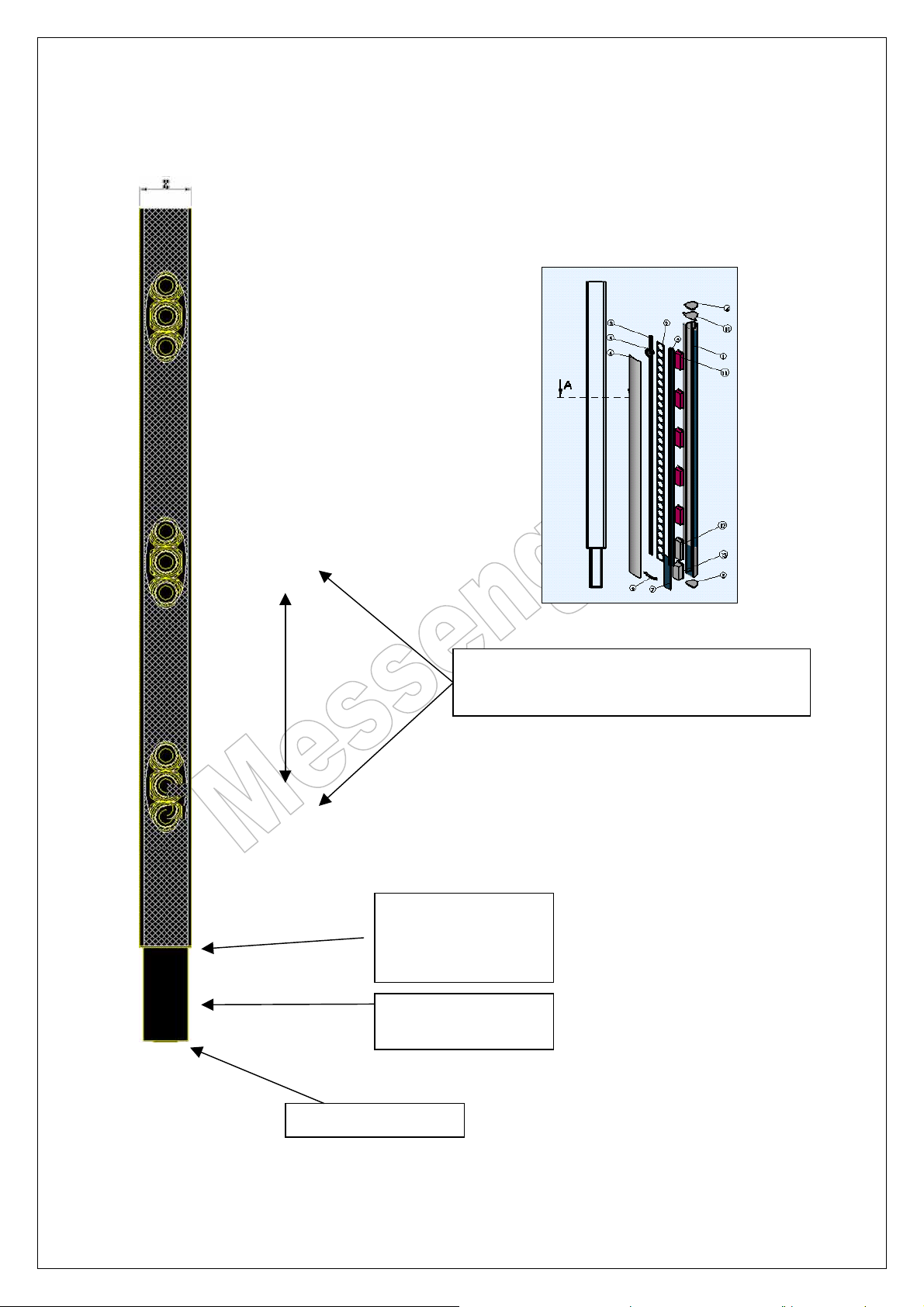
6. Product view:
Typical: Messenger XL
Acoustical centre can be chosen from asymmetric to
symmetrical or any position in between to match with
customer requirements.
Reference point for
acoustical mounting height.
Centre of the bottom driver
Service hatch with
connector department
Bottom of the array
Page 7 of 38
Page 8
Messenger Operating Manual
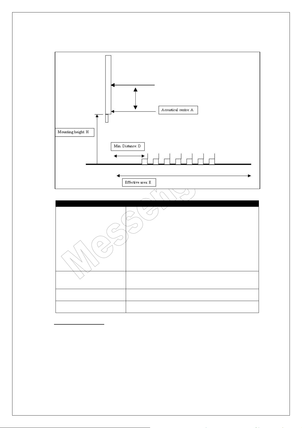
6.1. Mounting considerations:
Mounting instructions:
A: Acoustical centre When the acoustical centre is chosen in the lower range of the array,
an Asymmetrical lobe is generated. These are used in conjunction
with mounting heights between 1.8 and 4m from the floor and results
in a lobe that starts at 5m distance from the array at earlevel and ends
in a sharp lobe at 60m and further. The Asymmetrical lobe has the
ability to keep the sound deviation within 2 dB from 5 to 60m. Its
mounting height is NOT critical and therefore it is the most used
system solution. The vertical-opening angle is adjustable from 40
down to 5 degrees, with steering up to 30 degrees up and down.
The acoustical centre runs from A-symmetrical to Symmetrical, from
bottom to top in 9-steps.
H: Mounting height This height is measured between the floor and the bottom of the array
which starts at the bottom driver. (Small plate).
It is recommended to keep this height around 2mt.
D: Min. Distance This distance is measured from the front wall towards the first
listener’s position.
E: Effective range This distance is measured between the Messengers mounting
position and the last listener’s position.
Additional information:
Position: It is of vital importance that the Messenger is always placed in a rectangle
line with the listener’s plane. This ensures that reflected energy from the
back-wall stays in the acoustical centre and is not bounced into the ceiling
area where it might contribute artificial reverberation to the building
acoustics.
Opening angle: The vertical opening angle can be varied between 40 and 5 degrees.
Steering: Steering up to +/- 30 degrees.
Page 8 of 38
Page 9
Messenger Operating Manual
7. M-Control:
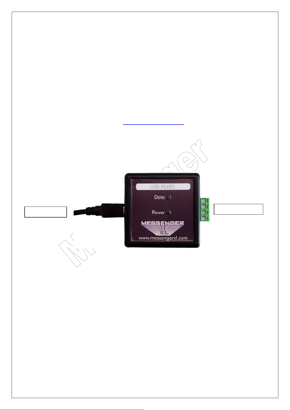
All versions are controlled using the M-Control USB - 485 interface. This interface is available
from the pricelist. This interface is an electronic device that can only be used in conjunction
with the Messenger series of products and in conjunction with FIRMWARE VERSION V2.15
or higher. The device allows easy system configuration via a PC-link that is supported by
Windows
The software is a development of Ateïs International SA and is license free, but only available
for key-dealers and distributors. The M-Control interface combines access control and datalink control and can be used as permanent interface or for configuration-use only. The
interface is delivered complete with a USB cable of approx. 1 meter and a CD with the
necessary driver software. The M-Control software and the Lobe-Assembler software are
also on this CD.
®
XP. (Other operating systems are not tested)
www.ateis-international.com
USB
RS 485 connection
Page 9 of 38
Page 10

Messenger Operating Manual
7.1. Unpacking and installation
The RS485 box should contain the following items:
• M-Control USB – 485 interface.
• USB connection cable, length: 1 m.
• Interface set-up manual.
• CD with drivers for the interface, the M-Control program for setting up
the Messenger(s) and this user manual.
Before using the RS 485 interface, please check if all the given items are present. Secondly,
be sure that the FIRMWARE VERSION of your Messenger is reading V2.15 or higher. Lower
versions will not provide complete functionality of the M-Control Software.
The interface set-up manual can be found with the interface..
8. Using the software
The M-Control and Lobe-Assembler software packages are easy to use and provide full
access to all system features of the Messenger. All menu pages and sub-menus are displayed
and can be opened by clicking the appropriated icon. If you select a sub-menu, close current
before opening new menu or submenu. The cursor movement, selection of parameters and
parameter settings can be established with the use of the mouse and keys.
It is important to note that you store changes into the Messenger before terminating the
software program. After every power shutdown, or software reboot, the Messenger will startup in its last saved configuration.
8.1. Minimum system requirements
The minimum system requirements to run the M-Control and Lobe assembler software
properly should be:
• PC-Pentium type with Windows® XP or higher
• Free disk space of approximately 25 Mb
• USB to RS 485 interface
8.2. Getting started
Insert the CD and click on “install M-Control and Lobe Assembler.
Install the drivers for the RS485 interface. (see the interface manual)
Latest version of M-control : Version 1.21
Latest version of the Lobe Assembler software : Version 1.10
Minimum firmware requirements of the Messenger : Version 2.15
(Firmware information can be found on the inside sticker in the connection
bay of the Messenger).
After you have finished the installation you can run both programs.
Page 10 of 38
Page 11
Messenger Operating Manual
8.3. Connecting to the Messenger using M-Control
8.3.1. Using the USB-485 interface:
The interface comes with a USB cable to connect the interface to the computer.
See the interface manual for installing the software for the interface and connecting
the Messenger(s) with the interface.
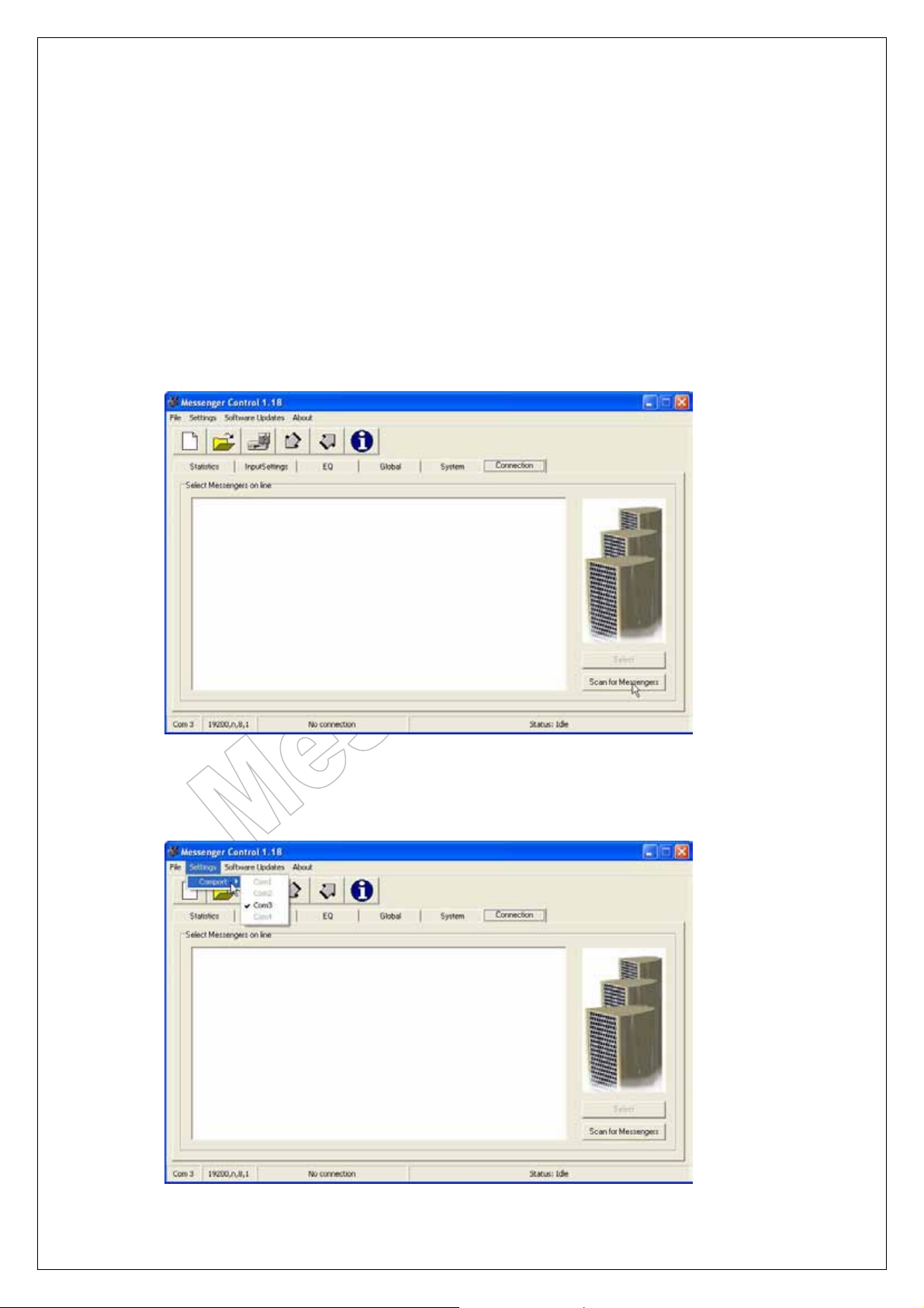
8.4. Establishing a connection between PC and Messenger:
Once you have made the connection between your PC and the Messenger, via the
USB – 485 interface start M-Control.
Startup screen of M-Control.
Select the COM port for communicating. Note that you can only select COM 1 till 4.
If all COM ports stay grey you have to set the USB-485 interface to a different COM
port. This has to be done in the Windows system settings menu.
Page 11 of 38
Page 12
Messenger Operating Manual
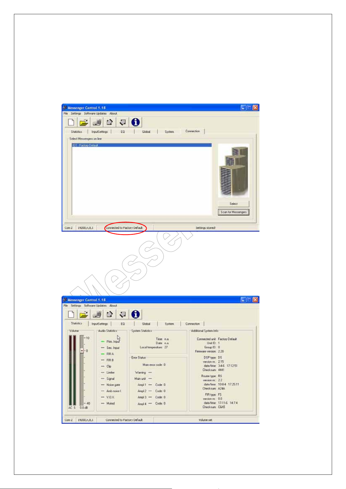
If you have a connection between the PC and the interface click on “scan for Messengers”
Note: The Messenger(s) must be powered-up for at least 20 seconds before the M-Control
program can detect them.
You will see the Messenger(s), which are present in the 485 loop.
Select the Messenger you want to control. In the bottom line of the screen you
can read the Messenger(s) you are connected to.
9. The program tabs and standard settings:
9.1. Statistics tab:
Here you can find the general information about the selected Messenger.
Page 12 of 38
Page 13
Messenger Operating Manual
9.2. Input Settings tab:
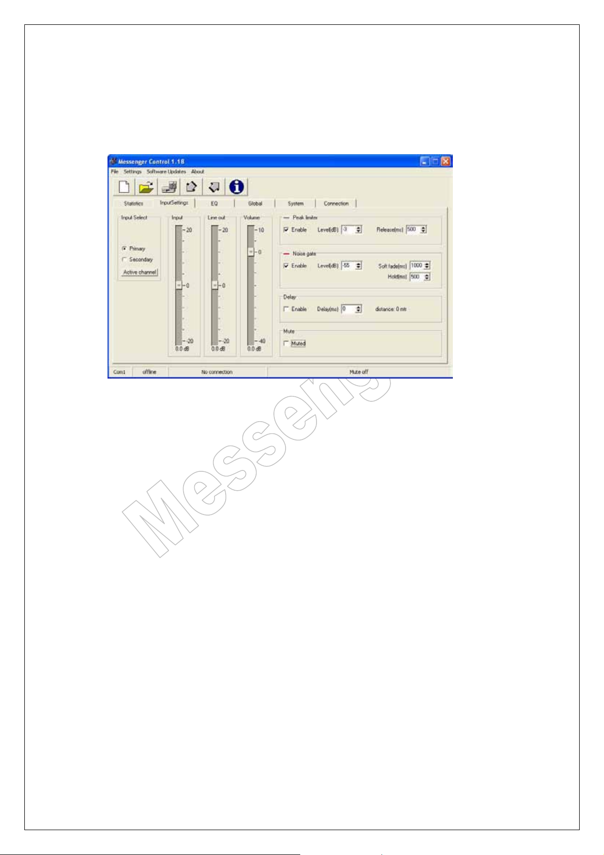
If you are accessing a new Messenger (Factory Default) in the “input Settings” tab
the settings are as in the windows below.
9.2.1. Primary input:
INPUT SENSE Sets the input sensitivity of the primary input. By default this is
set to 0 dB.
LINE OUT Sets the output level to the next Messenger. By default this is
set to 0 dB.
VOLUME Sets the direct audio level of the primary input. By default this
is set to 0 dB.
NOISE GATE Is by default enabled and can be adapted to the situation by altering
the values in the boxes: Level, Hold and Soft fade (out).
PEAK LIMITER Is by default enabled and set at –3dB. It is our strong recommendation
that the peak-limiter stays enabled. It is for protection reasons. If high
SPL levels are required the limiter could be set to 0 dB. This will still
limits the audio at 0,1 dB before the AD converter starts clipping.
DELAY Maximum delay setting is 1000 ms.
MUTE Audio MUTE mutes the primary input. It does not mute the audio path
from the audio-slave output.
Page 13 of 38
Page 14
Messenger Operating Manual
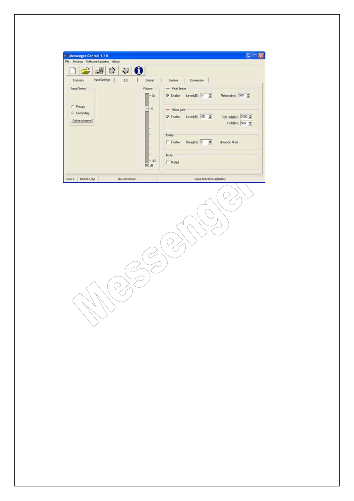
9.2.2. Secondary input:
VOLUME Sets the direct audio level of the secondary input. By default this is
set to 0 dB.
NOISE GATE Is by default enabled and can be adapted to the situation by altering
the values in the boxes: Level, Hold and Soft fade (out).
PEAK LIMITER Is by default enabled and set at –3dB. It is our strong recommendation
that the peak-limiter stays enabled. It is for protection reasons. If high
SPL levels are required the limiter could be set to 0 dB. This will still
limits the audio at 0,1 dB before the AD converter starts clipping.
DELAY Maximum delay setting is 1000 ms.
MUTE Audio MUTE mutes the secondary input.
Page 14 of 38
Page 15
9.3. E.Q. tab:
Messenger Operating Manual
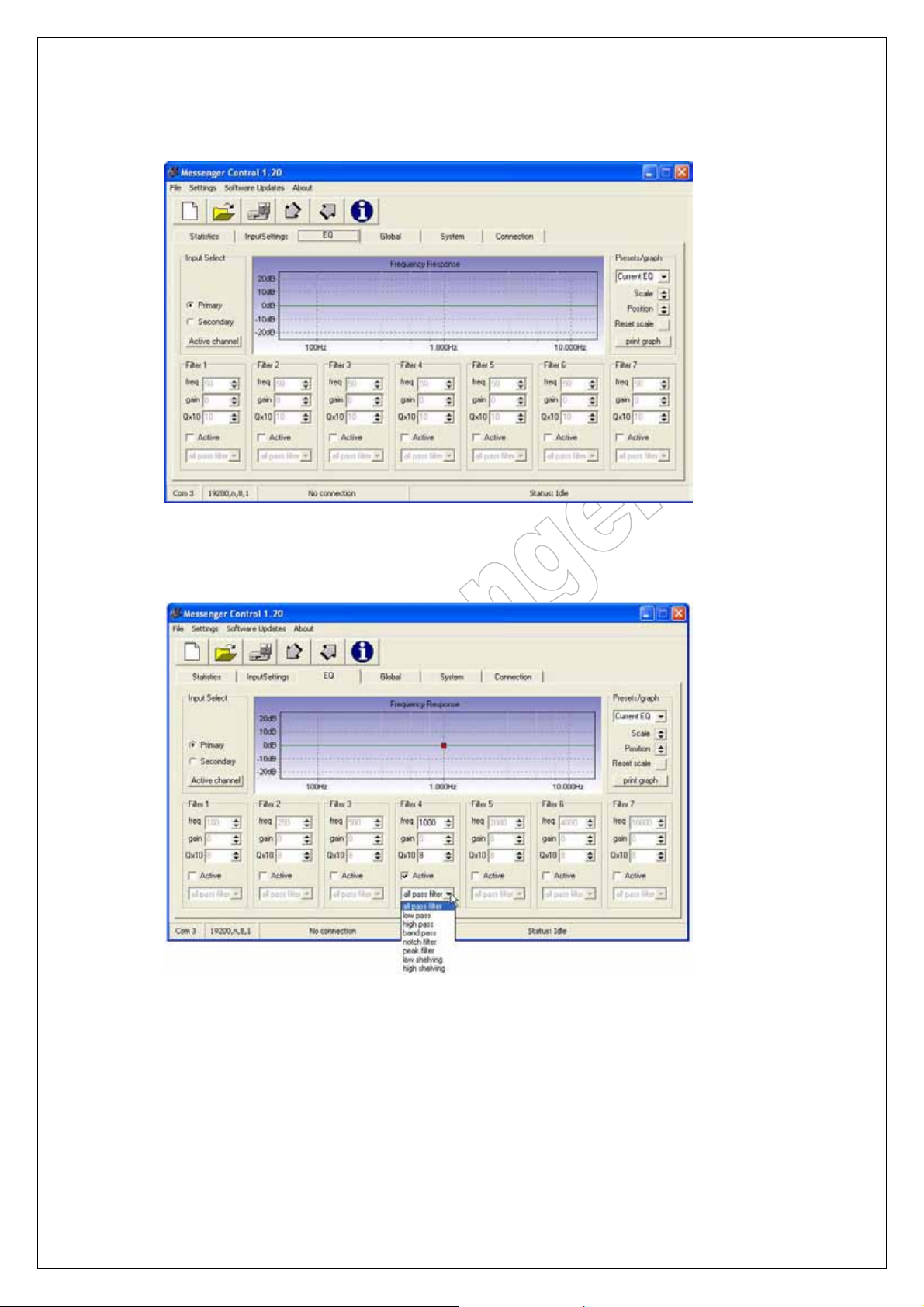
Changes made in the EQ settings are directly effecting the settings of the Messenger.
9.3.1. Filter selection:
The EQ-folder provides 7 free addressable filters. Every EQ has the following
pre-selectable filter-characteristics:
- All pass (Phase shifting)
- Low pass (high-cut)
- High Pass (low-cut)
- Low Shelving (Tone control)
- High Shelving (Tone control)
- Band pass
- Notch filter (Anti –feedback)
- Peak filter (Room resonance’s)
Page 15 of 38
Page 16
9.3.2. Presets:
Messenger Operating Manual
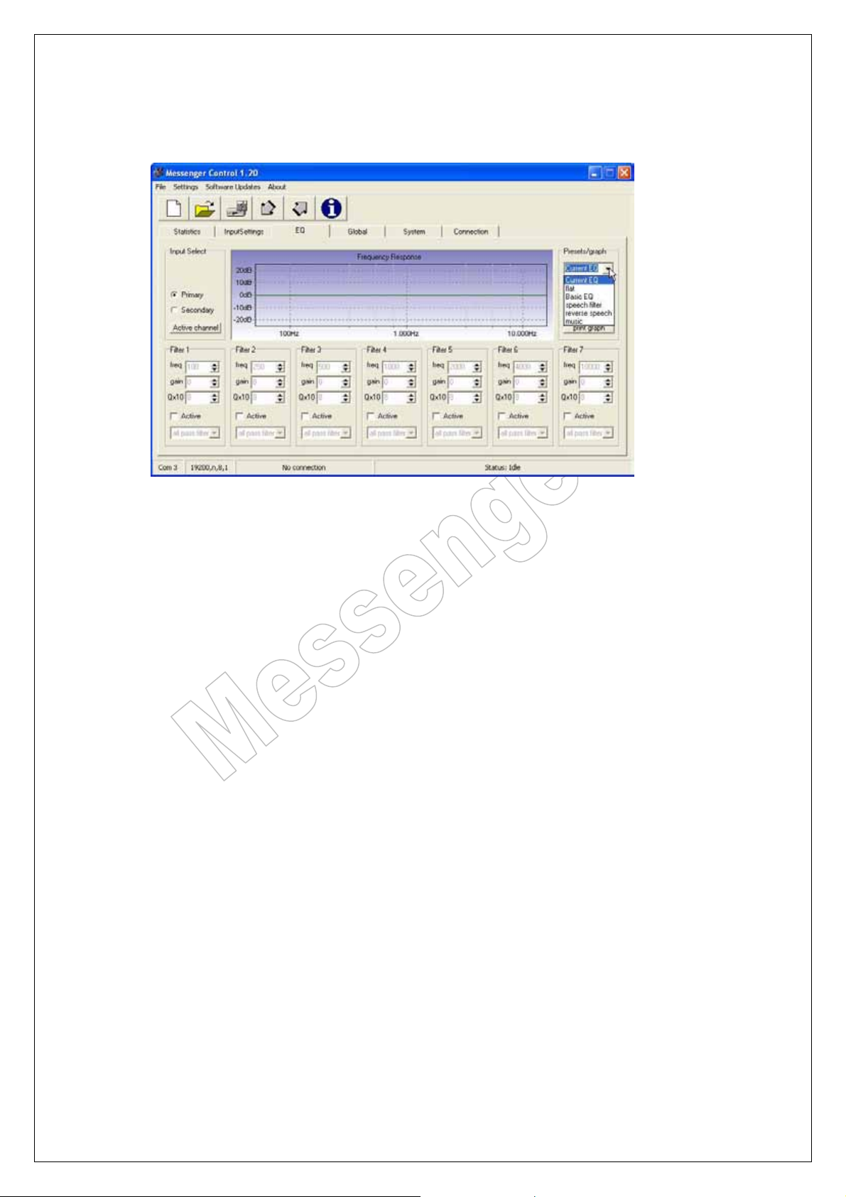
Here you can select several factory-pre-set settings for the EQ.
Note that the primary and secondary input have their own EQ.
Page 16 of 38
Page 17
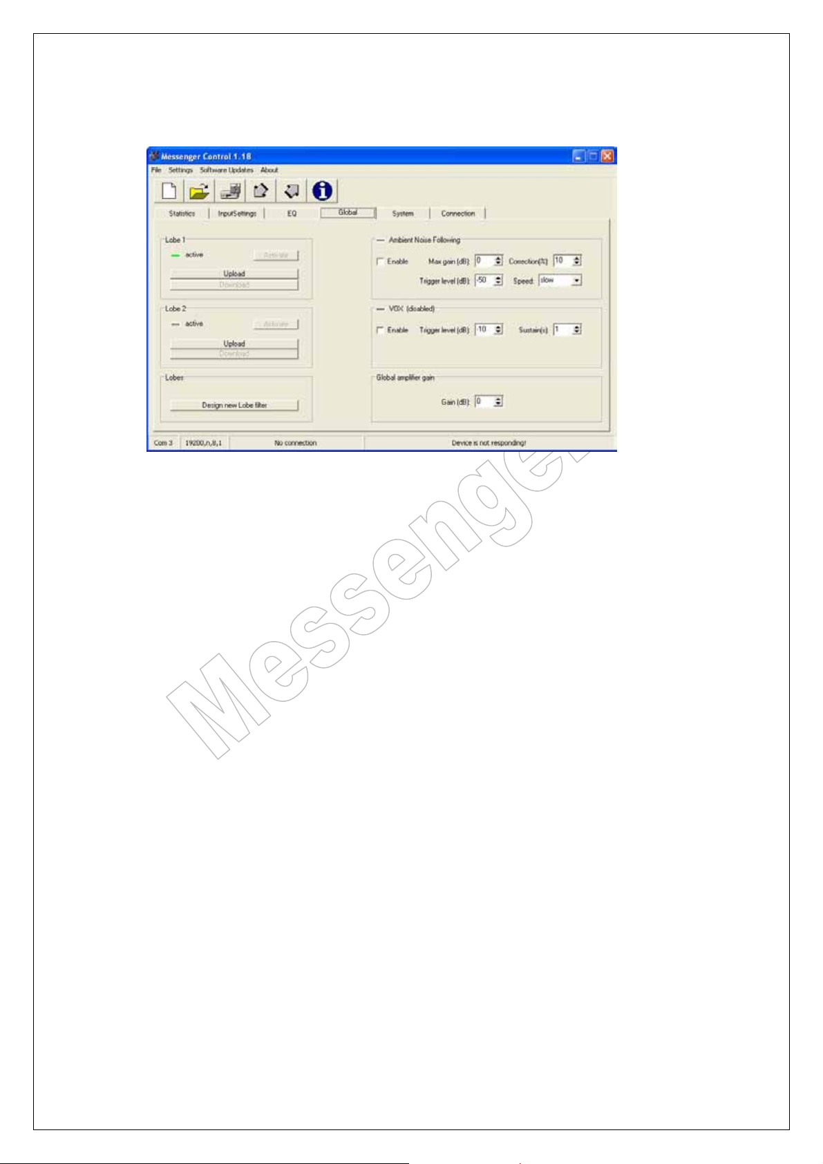
9.4. Global tab:
Here you can upload Lobe files, set the amplifier gain, and several other things
described in this chapter.
There is the possibility to store two different Lobe files in the memory of the Messenger.
The selection of the Lobe is done with a contact closure. For further information see the
description of the input board.
Messenger Operating Manual
Page 17 of 38
Page 18
Messenger Operating Manual
9.4.1. The UPLOAD of a LOBE (FIR-File)
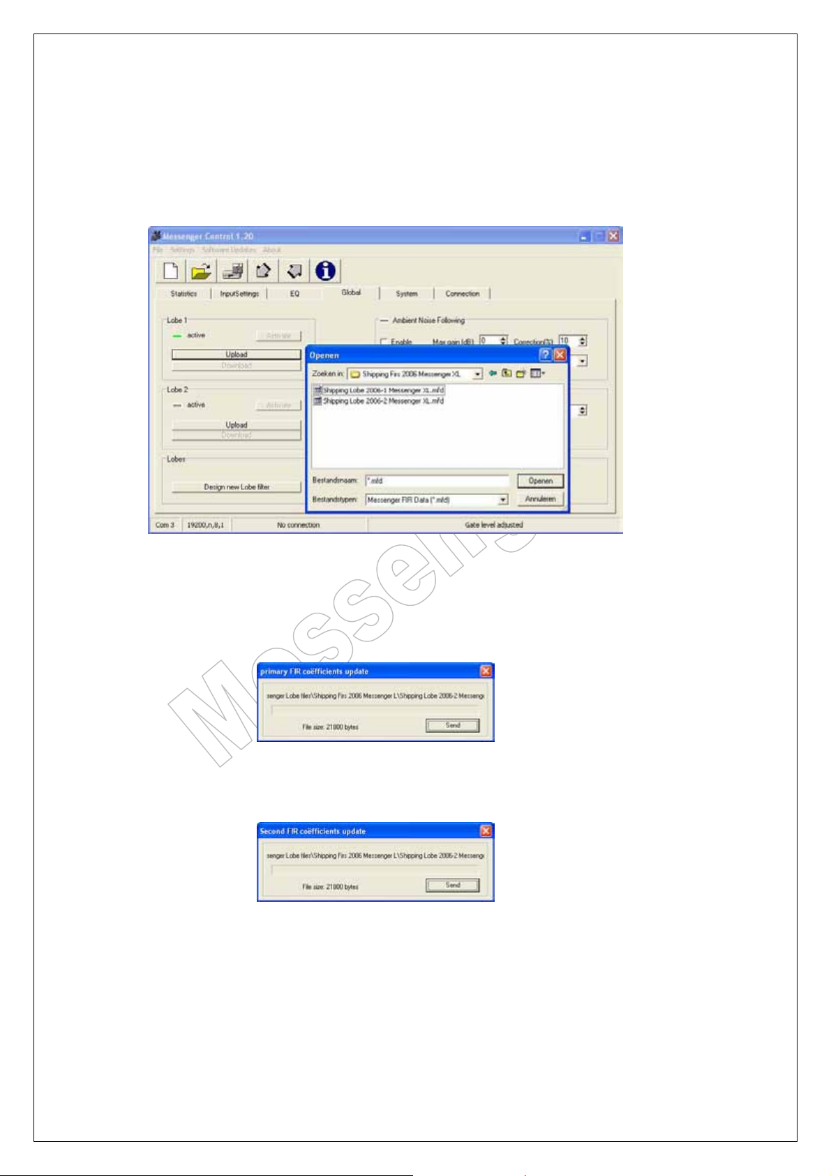
To upload a lobe, you first have to generate a FIR file from the Lobe-Assembler software.
(See section 4 of this manual). The file will carry the file extension: *.mfd (Export file from Lobe
Assembler)
Click on Upload (Lobe1 or Lobe2) and select the MDF (Messenger Fir Data)
you want to load in the Messenger.
For uploading the data into the Lobe1 section you get the following screen:
For uploading the data into the Lobe2 section you get the following screen:
Click on send.
A running bar will show you the time remaining for the upload. During the upload the
unit will not pause its functioning, so an upload or lobe-change could be done during
a live performance. After loading the lobe click on activate.
It is advised to reset the Messenger after the upload of a new Lobe file.
The reset procedure is described in the System tab.
Page 18 of 38
Page 19
Messenger Operating Manual
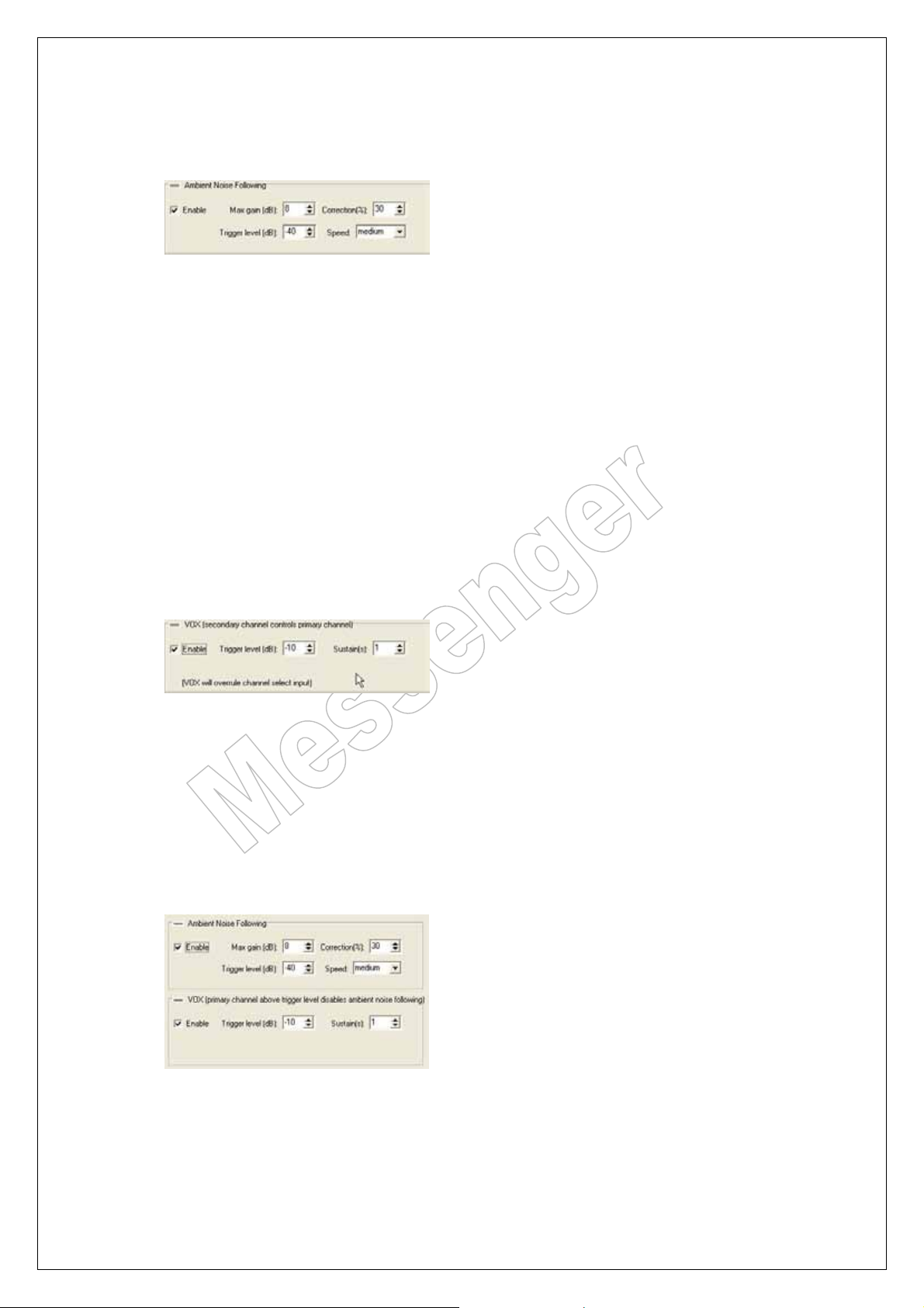
9.4.2. Ambient noise following.
If Ambient noise following is activated the secondary input is turned into a measuring input.
This input accepts line signals. If a sensing microphone is connected we advise you to use
the SD 1 expansion input board. For all the details of the SD 1 expansion board we refer to
the appendix.
Max gain; determinates the maximum additional amplification.
Trigger level; is the point where the additional amplification starts.
The LED lights up when the trigger level is reached.
Correction; is the ratio between the level above trigger level and the increase in volume gain.
Example (correction is set at 30%):
if the Ambient noise level is 10dB above trigger level the volume gain will be 3 dB.
Speed; (slow – medium – fast) sets the reaction to changes the sensing
microphone is reregistering.
9.4.3. VOX
In this setting the secondary input can be used as alarm input.
If the audio level, on the secondary input, reaches a certain level
this signal overrides the primary input.
Trigger level; sets the point where the secondary input becomes active.
The LED lights up when the trigger level is reached.
Sustain; sets the hold time of the Vox in seconds.
9.4.4. Ambient noise following and Vox both on.
When those two functions are set on together the Ambient noise following function is set
with an extra feature. The Vox is now working as a threshold on the primary input.
This feature means that if the audio level on the primary input reaches the trigger level the
Ambient noise sensing is stalled at the correction value of that moment.
Page 19 of 38
Page 20
Messenger Operating Manual
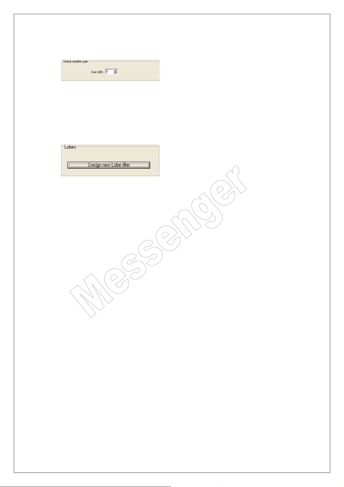
9.4.5. Global amplifier gain:
This sets the gain of all the amplifiers. It can be set between –10dB and + 10dB.
Default setting is 0 dB.
For normal situations it is advised to keep the default setting. Only when a higher
SPL level is needed correct it upwards.
9.4.6. Design new Lobe filter.
This starts the Messenger Lobe Assembler program.
Page 20 of 38
Page 21
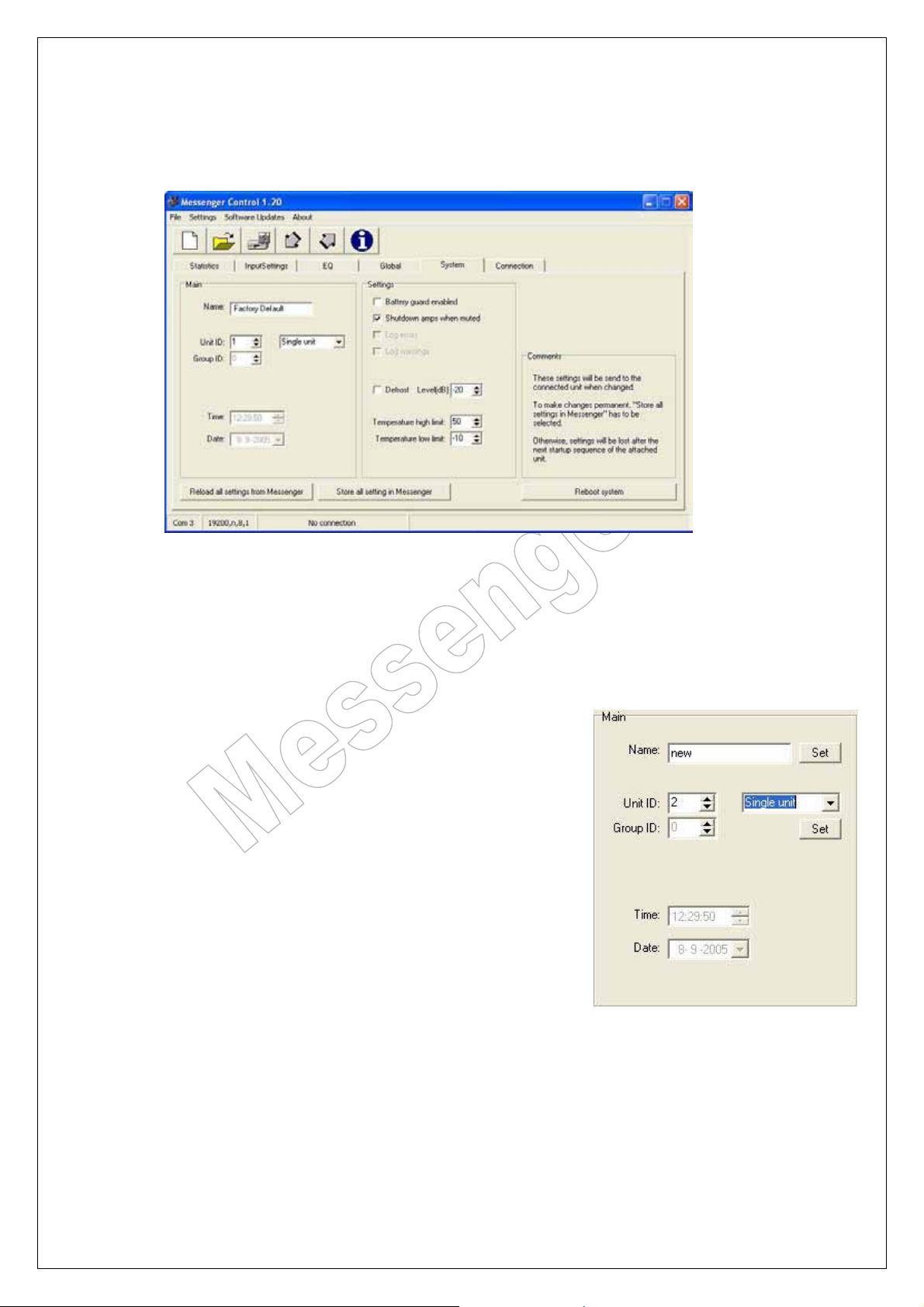
10. System tab:
Messenger Operating Manual
These are the default settings.
10.1. Main settings:
Here you can change the name and
the ID of the unit.
Changing the name; simply type the name and click
on the set button. The new name is now stored into the
Messenger. Then go to the connection tab and click on
“scan for new Messenger”. This is the only right procedure
to change the name.
Changing the unit ID; Alter the ID number and click on set.
The number has to be between 1 and 32.
Then go to the connection tab and click on “scan for new
Messenger”. This is the only right procedure to change the
name.
Here you can also select the type of unit. If the messenger
is a 2L or 2XL type the bottom unit is the master and the
top unit is the slave unit. The master and the slave unit
must have the same Unit ID.
Page 21 of 38
Page 22
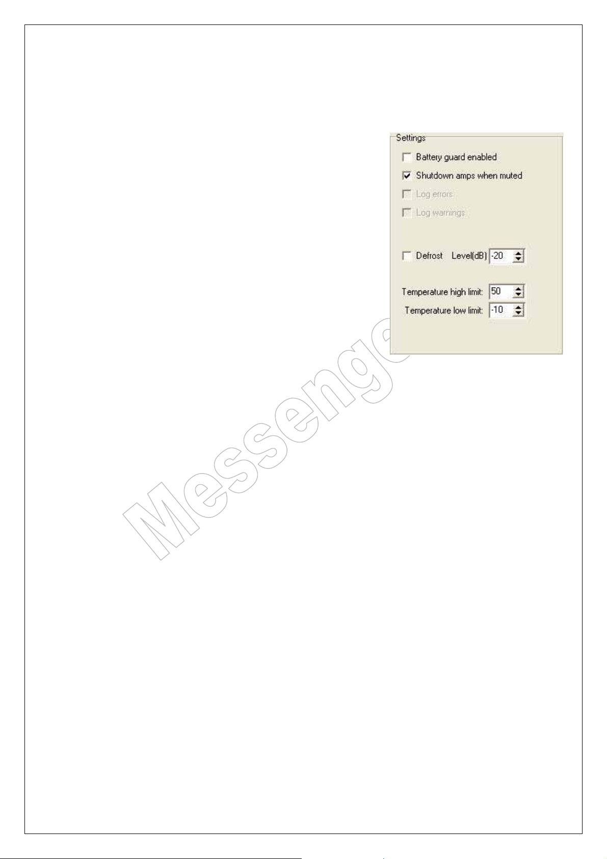
10.2. Settings.
Battery guard:
Default setting off.
When a battery backup is connected to the Messenger it is
possible to guard this connection if the (24-Volt) battery
backup is present. If battery guard is activated and the 24
Volt backup is not present an error can be seen in the
statistics tab. There is also a possibility for a remote
warning via the Pre-warning switching contacts.
Shutdown amps when muted:
Default setting activated.
This option is to minimise, heat dissipation and energy
consumption when idle.
Defrost:
Default setting off.
This function is only used in special situations where
Messengers are used in the WP version. This is a special
version of the Messenger that can be used in outdoor
situations. If there is a risk that the temperature will drop
below 2 degrees Celsius the defrost function can be set on.
Then the loudspeakers will be kept moving in a sequential
mode. Note that this will not work if the temperature drops very low.
Than other protection measures have to be taken.
Messenger Operating Manual
Temperature high and low limit:
Default settings 50 and –10 degree.
If the temperature inside the Messenger is reaching
these limits the warning status is activated.
Page 22 of 38
Page 23
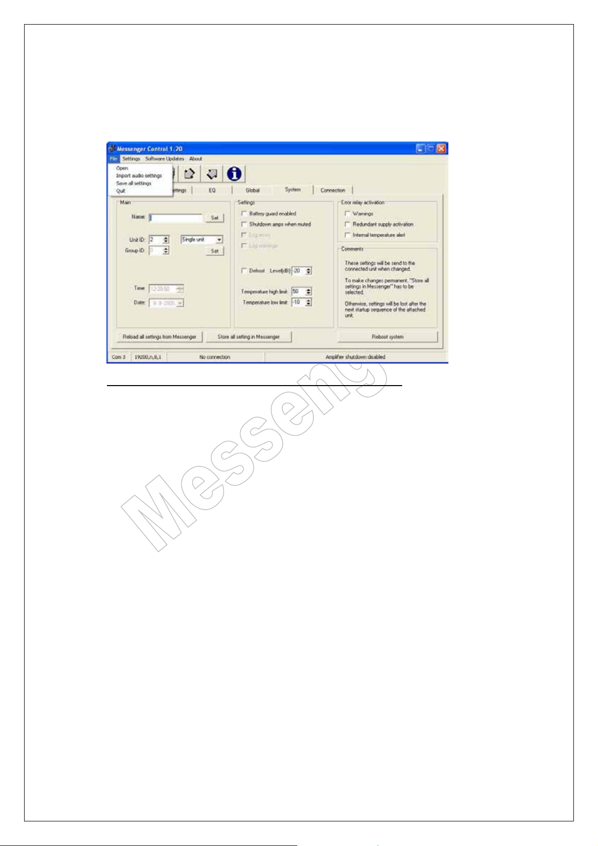
Messenger Operating Manual
11. Save your data
All audio settings can be saved and also reloaded into the Messenger
Please note that only the audio settings can be stored on this way.
The other information like unit ID, unit name etc. is not saved in this file.
Also the lobe(s) loaded into the Messenger are not saved in this file.
For saving the Lobe(s) and Fir filters see the part concerning these items.
Page 23 of 38
Page 24
Messenger Operating Manual
12. Messenger Lobe Assembler software
12.1. General information about Lobe-Assembler:
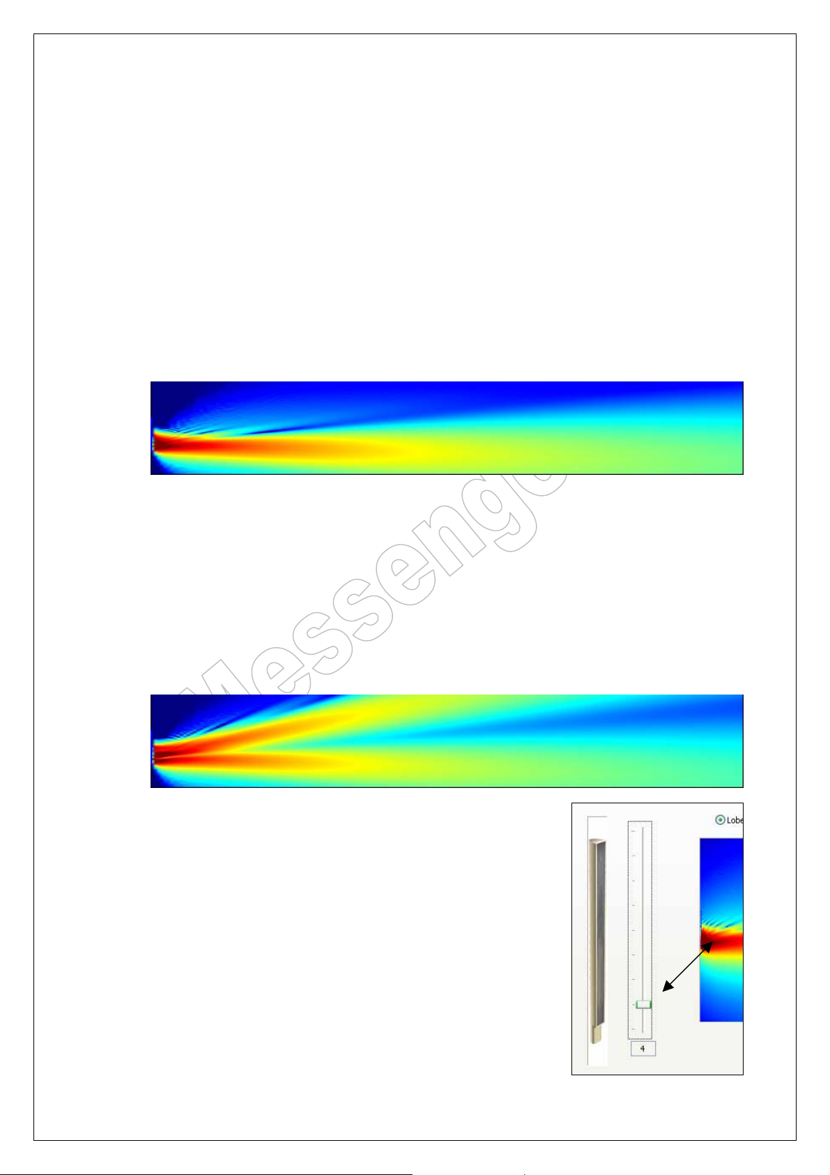
The Messenger Lobe-Assembler software allows you to create your own lobes. Lobes are
described as the output result of the array. Based on the chosen opening angle, steering
angle and focal point, a sound output is created that will cover the audience area. This output
is called a lobe. A lobe picture is normally shown in the way of a hot flame that comes from a
certain point of the array, acoustic centre, and is thrown into the room. The hotspot of this
flame is shown in the colour red. Any colour decline from red to green means a signal decay
from loud to a lower level. Same colour at earlevel, means an even signal pattern. Using the
cursor or a reference line, the signal decay versus distance can be visualised by means of
figures or as graph.
This is a typical lobe picture:
The Messenger Lobe Assembler program shows you the direct energy distribution in an
anechoing chamber. Lobe Assembler is therefor not a prediction program. Its is only useful to
get information about the direct energy and the expected signal decay. It also allows you to
calculate second and third lobes for balconies and for lobe-merging.
Lobe merging can be useful if you have to cover seats over great distances where the signal
needs to be tuned for near, middle and far-field. This way you can tune a lobe such that the
far-field lobe is gained in signal without causing any feedback effects on the near-field
microphones.
This is a typical dual lobe picture for ground section and balcony:
Beside the choices for opening angle and focal points, the Lobe-
Assembler also allows you to select an acoustic centre. The
acoustic centre defines the basic shape of the lobe. It is selectable
from A-symmetric to symmetric in 9 steps. This function allows for
more flexibility when it comes down on mounting heights and
mounting facilities. The Messenger XL, therefor, can be positioned
at various heights starting from 1.60 up to 4 meters, counting from
the audience groundsection.
(The slider position shows the acoustic centre of the lobe on
driver number 4. Moving the slider up, will change the basic shape
of the lobe.)
Page 24 of 38
Page 25
Messenger Operating Manual
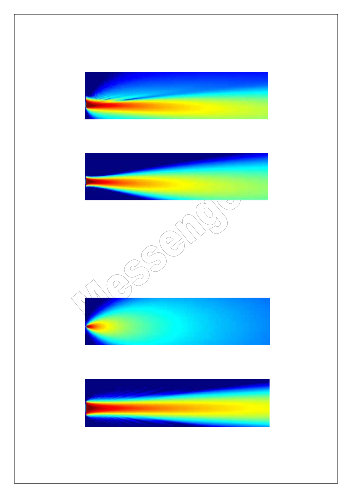
For the groundsection coverage an A-symmetrical lobe is more common to use. For a remote
balcony a symmetrical lobe is more common.
Typical A-symmetrical lobe shape with the acoustic centre on driver number 4:
Typical Symmetrical lobe shape with the acoustical centre on driver number 13:
Beside the adaptable acoustic centre, every chosen lobe has a variable opening angle, which
is selectable from max. 45 degrees to a minimum of 5 degrees. With this function together
with the selected height of the speaker, an even signal pattern can be accomplished. It is also
known that a 5 degrees penetrates the environment much better than one with a bigger
opening angle. It is therefor useful to build a lobe out of two lobes when you have to deal with
a long throw to reach the last seats. (@ 40 – 50 mt). The far-field lobe could be a 10 or 5
degrees one and is focussed on the last seat. A near-field one could be a 15 or 20 degrees
one with an azimuth/tilting of app. 12 degrees.
Typical 45 degrees shape:
Typical 5 degrees shape:
Page 25 of 38
Page 26
Messenger Operating Manual
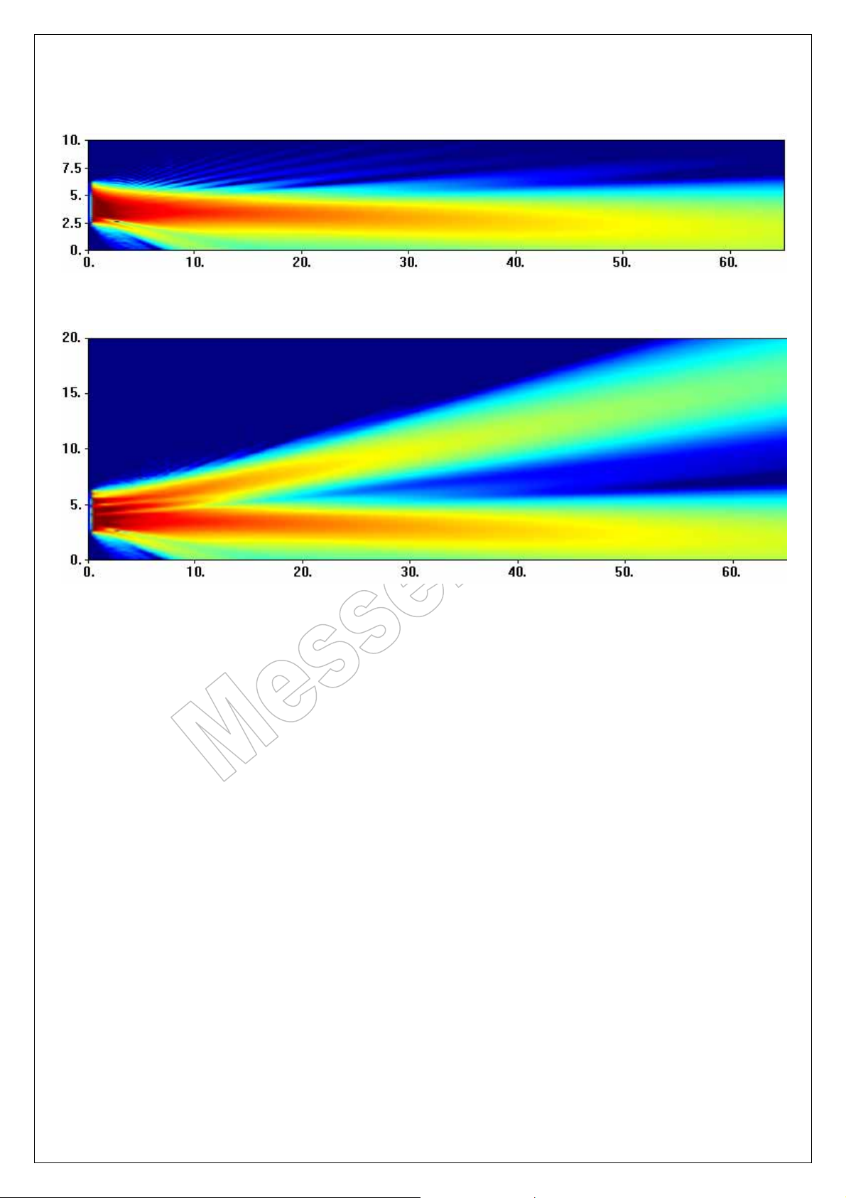
Typical dual-lobe set-up for near and far-field coverage (Dimensions are in meters):
And, if that is not enough, a triple-lobe version that also covers for the balcony
(Dimensions are in meters):
Whatever you do with the Lobe-assembler software and the Messenger XL, it is clear that
side-lobes do not appear. This is one of the key features of the Messenger technique. No
side-lobes means, no outrages feedback frequencies, so easier to tune and more gain!!!
Page 26 of 38
Page 27
Messenger Operating Manual
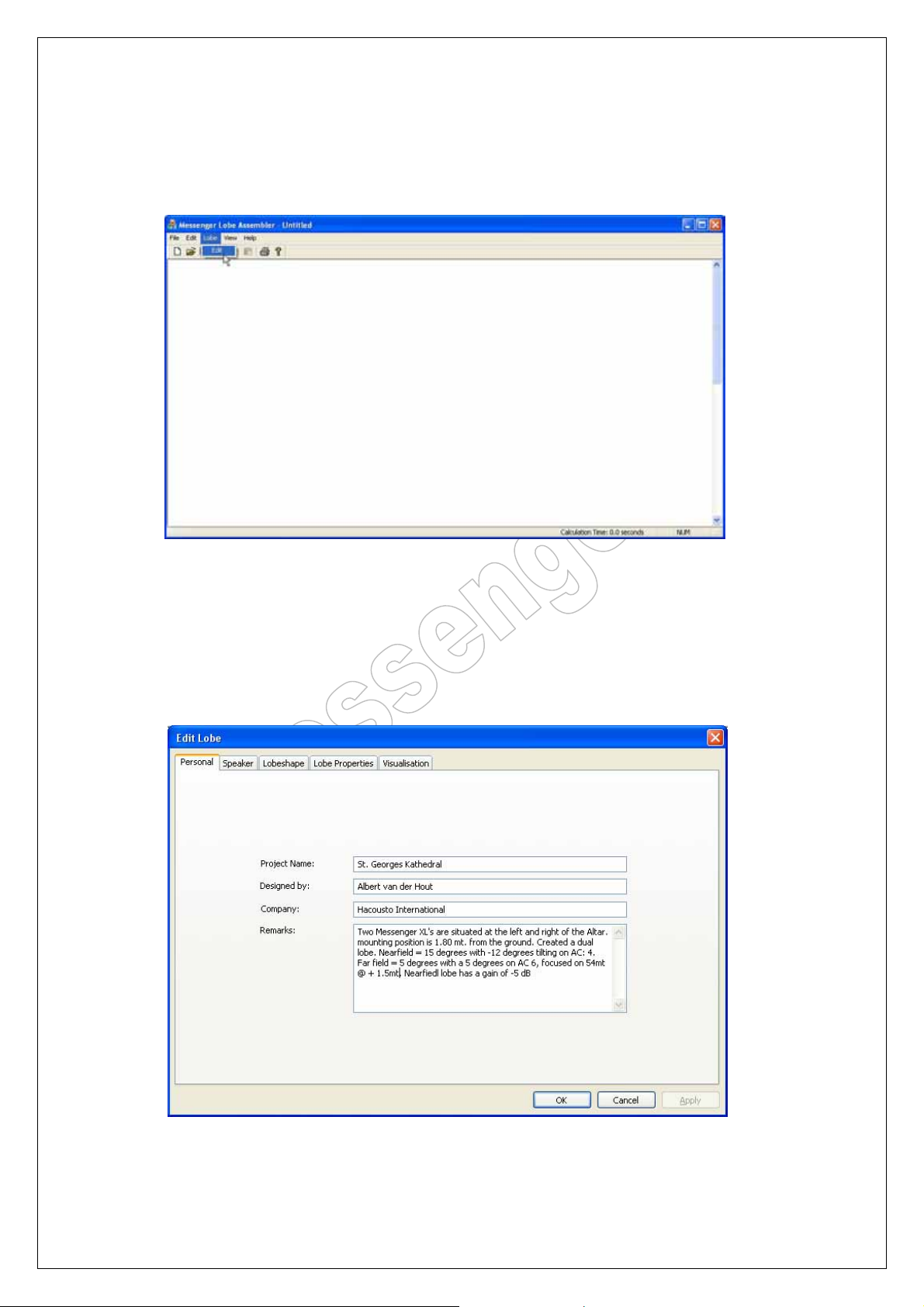
12.2. How to start with the Lobe-assembler software:
Extract all data into one directory of your choice. Then run the *.exe. This will open the
following screen:
From the top-bar, select ‘EDIT’ to open the edit-lobe menu. Or, alternatively, click on ‘FILE’
and ‘OPEN’ to select a previously saved project. You can also drag and drop project data from
explorer directly into any Lobe-Assembler window.
Every time you press on the button ‘OK’, the result is calculated. In this stage you better go
through all the folders before you press on the button ‘OK’.
12.3. Personalising of your project file:
When you are going to build a new project, ‘EDIT’ is the function to start with.
Page 27 of 38
Page 28
Messenger Operating Manual
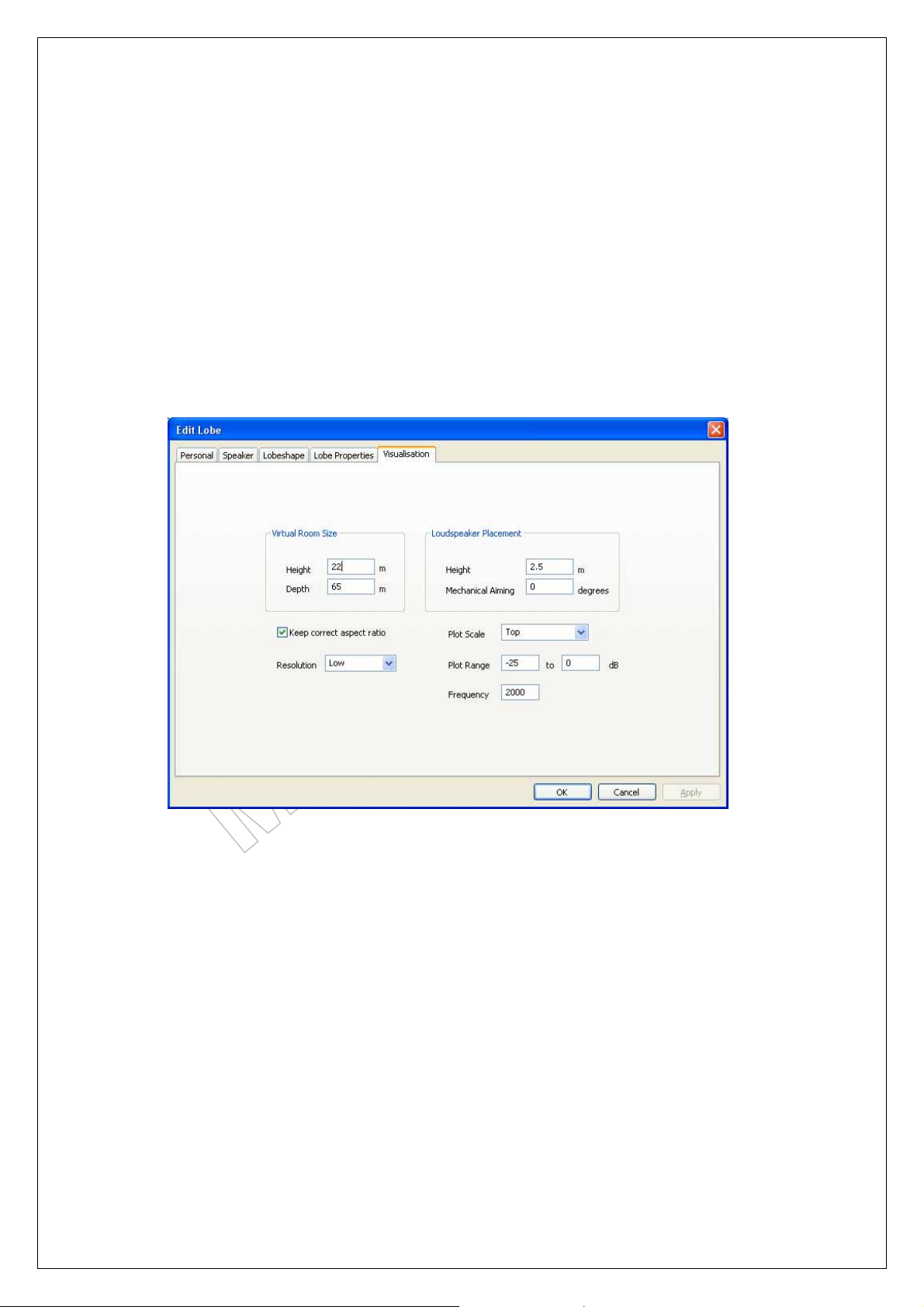
The first folder that you see is the ‘PERSONAL, folder. Here you put all your relevant project
data. This data is also stored in the project file that can be saved and the essential data like,
lobe building data is also stored in the messenger together with the exported FIR/LOBE file.
These essential data files will be visualised in the next version on M-Control.
Everytime you press on the button ‘OK’, the result is calculated. In this stage you better go
through all the folders before you press on the button ‘OK’.
12.4. Visualisation screen:
In this screen you define the building data, like height, depth, height of the Messenger and the
frequency you want to evaluate. The field ‘RESOLUTION’ sets the image resolution that is
presenting the results on the screen of your PC. It has no influence on the results of the
calculated lobe. The resolution set to high just extents the calculation time, but it might be
required that you want to use a high-resolution picture for presentation purposes.
Everytime you press on the button ‘OK’, the result is calculated. In this stage you better go
through all the folders before you press on the button ‘OK’.
Functions:
Virtual Room Size:
Height Height of the ceiling.
Depth Depth of the object
Loudspeaker Placement:
Height Height of Messenger, measured from the floorlevel to the first driver.
Mech. Aiming If the Messenger is not placed 100% vertical, you can compensate for the
angle + and -. (We refer to the installation manual for more detailed
information)
Resolution Low, Middle, High. Sets picture quality
Plot scale Top, Bottom, left, right. The dB scaling position.
Frequency The lobe results at the given frequency
Note: It is proven that the 2000 Hz result matches with PINK-NOISE measurements in the
field. And it is easy to listen at. Other frequencies need to be played as sinewave and
measured as sinewaves. See it as a practical tool.
Page 28 of 38
Page 29
Messenger Operating Manual
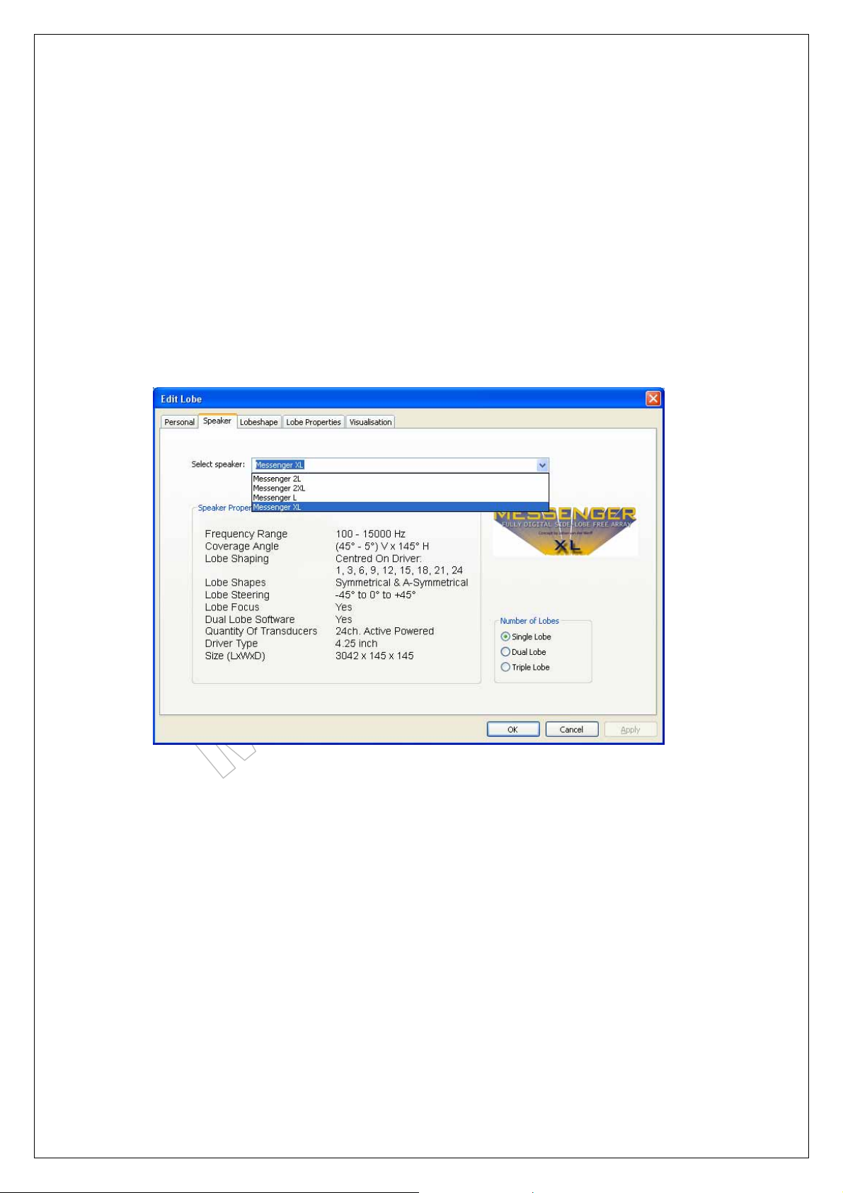
12.5. Speaker choice:
In the next menu you have to select what type of Messenger to use for your application.
You can choose from:
Messenger L: an 18-way Array. Only restriction on this type is the minimum opening
angle of 10 degrees, which is related to its reduced size.
Messenger XL: a 24-way Array.
Messenger Two-L: Two Messenger L units, linked as one to a 36 way Array.
Messenger Two-XL: Two Messenger XL units, linked as one to a 48 way Array.
All Messengers have:
Triple lobe capabilities, 9-steps adaptable acoustic centre, variable opening angles, full
pre-processing controls, variable mounting heights from 1.60 up to 4 mt.
From the pull-down menu you simply select the type you want to use. From the ‘NUMBER
OF LOBES’ field you select a single, dual or triple lobe set-up. You can always start with a
single lobe version and add a second and a third in a later stage of your design work.
Everytime you press on the button ‘OK’, the result is calculated. In this stage you better go
through all the folders before you press on the button ‘OK’.
Page 29 of 38
Page 30
Messenger Operating Manual
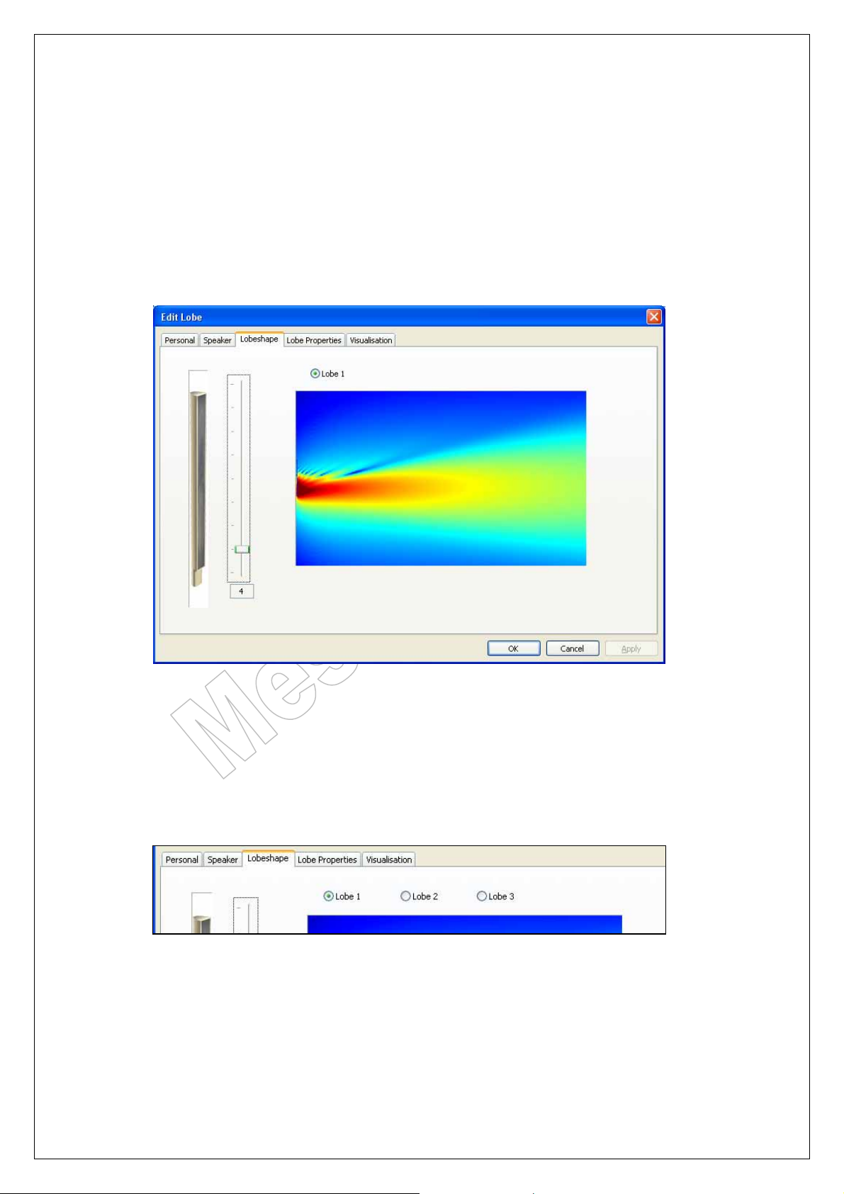
12.6. Lobe shape selection:
One of the unique features of the Messenger is that you can adapt the acoustic centre to
accommodate for the required mounting height. Depending on the mounting position of the
speaker, you can change the acoustic centre and with that the basic lobe shape from Asymmetrical to symmetrical and reversed. Every type of messenger, L, XL, Two-L and TwoXL, have 9 acoustic centres that define the basic shape and application of the lobe.
A typical A-symmetrical shape is used for the typical ground section coverage, symmetrical
lobes are more likely to be used for remote placed balconies.
Every basic lobe is to be post-processed within the lobe-assembler software.
Moving the slider up and down will alter the basic shape of the lobe from A-symmetrical on
driver number 1 to symmetrical on driver number 13 to reversed a-symmetrical on the top
driver number 24. (In case of the XL).
The number at the bottom of the slider indicates the driver number that corresponds with the
acoustic centre.
In case you have chosen for a dual lobe set-up or a triple-lobe set-up, the tickerbox at the top
will allow you to jump from one lobe to the other, where you can define its basic shape.
Every time you press on the button ‘OK’, the result is calculated. In this stage you better go
through all the folders before you press on the button ‘OK’.
Page 30 of 38
Page 31
Messenger Operating Manual
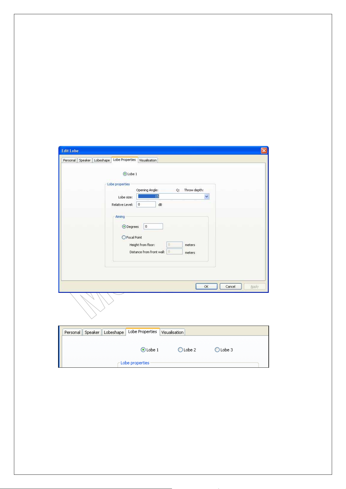
12.7. Lobe properties:
Once a basic lobe has been selected from the previous menu, you have to post process the
lobe to your need. For this you have access to the following settings:
Lobe size: Opening angle in steps of 5 degrees from 5 to 45 degrees
(With exception of the ‘L’, that goes from 10 to 45 degrees)
Relative level: If a second and third lobe is activated, the level of the lobe can be
raised or lowered from the 0 dB reference level. This way you can
gain the level at certain positions in the room.
Degrees: Is the steering angle. + means steering up, - means steering down.
Focal point: If you do not know the steering angle, you can also fill out the data
required for the focal point that will exactly bring the lobes acoustic
centre through your measuring point.
In case you have chosen for a dual lobe set-up or a triple-lobe set-up, the tickerbox at the top
will allow you to jump from one lobe to the other to alter the settings.
Now is the time you can select the ‘OK’ button to let the program run for result. The result is
showing the direct energy, as the Messenger would be positioned in an anechoing chamber.
Page 31 of 38
Page 32
Messenger Operating Manual
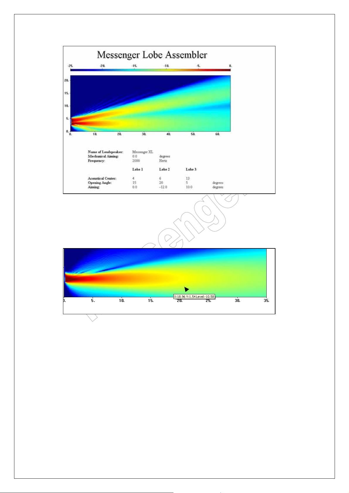
This could be one of the results when a triple lobe set-up was selected. Two lobes for the
ground field, one for the far and one for the near, and one for a balcony.
Use the mouse to go through the picture and check for the direct SPL results on the listening
plane. Too much variation? Go back and retune the lobe by changing focal points, relative
gains or opening angles.
The arrow shows the X, Y and level value. Y = height.
Make sure that the level does not varies more than 2 dB.
Page 32 of 38
Page 33
Messenger Operating Manual
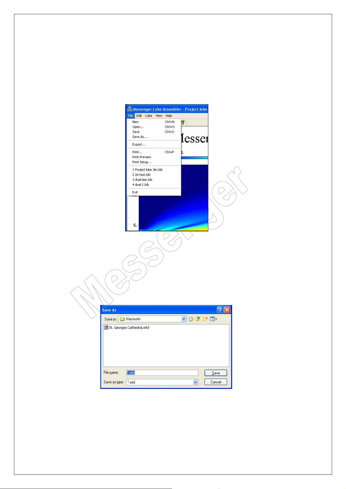
12.8. Save and exporting FIR data:
12.8.1. Save your project data:
Last step is to save the project data once you have finished your project. For this select
‘SAVE’ from the ‘FILE’ menu at the top bar and save the project. Every project will carry the
extension *.lob
12.8.2. Exporting a FIR-file or Lobe-file:
Once you have finished your project and saved your project data, you want to listen to the
results of the lobe you have just created. To do this, you have to ‘EXPORT’ the data. Go to the
‘FILE’ menu and select ‘EXPORT’. A box will open asking you to name the FIR-lobe data,
which than will be stored with the extension: *.mfd
Now your file is ready for use and can be uploaded using M-control. For instructions, follow
the instructions as described in section 2.5 of this manual.
Page 33 of 38
Page 34
Messenger Operating Manual
13. Examples:
There are many ways of building and creating lobes. Because of the many possibilities it is not
un-usual that you will not gain the maximum results the first time. It is also very unusual for a
sound engineer to shape a lobe where in earlier days the only way of directing sound was my
means of re-positioning the speaker or cluster or by choosing a different type of speaker.
This array technique has many benefits, but to be able to use it to the max you have to
develop a feeling for it. This is the reason why we have put in this chapter with examples. We
hope that we can extent this section and fill it with all your experiences. So please feel free to
share your experience with us by sending your lobe with comments to:
From our experience 8 out of 10 lobes are build the following way and are in this way the most
successful to start with, giving the best gain before feedback and the highest STI results.
The projects can be downloaded from our website from the User site. Just look for the Project
number.
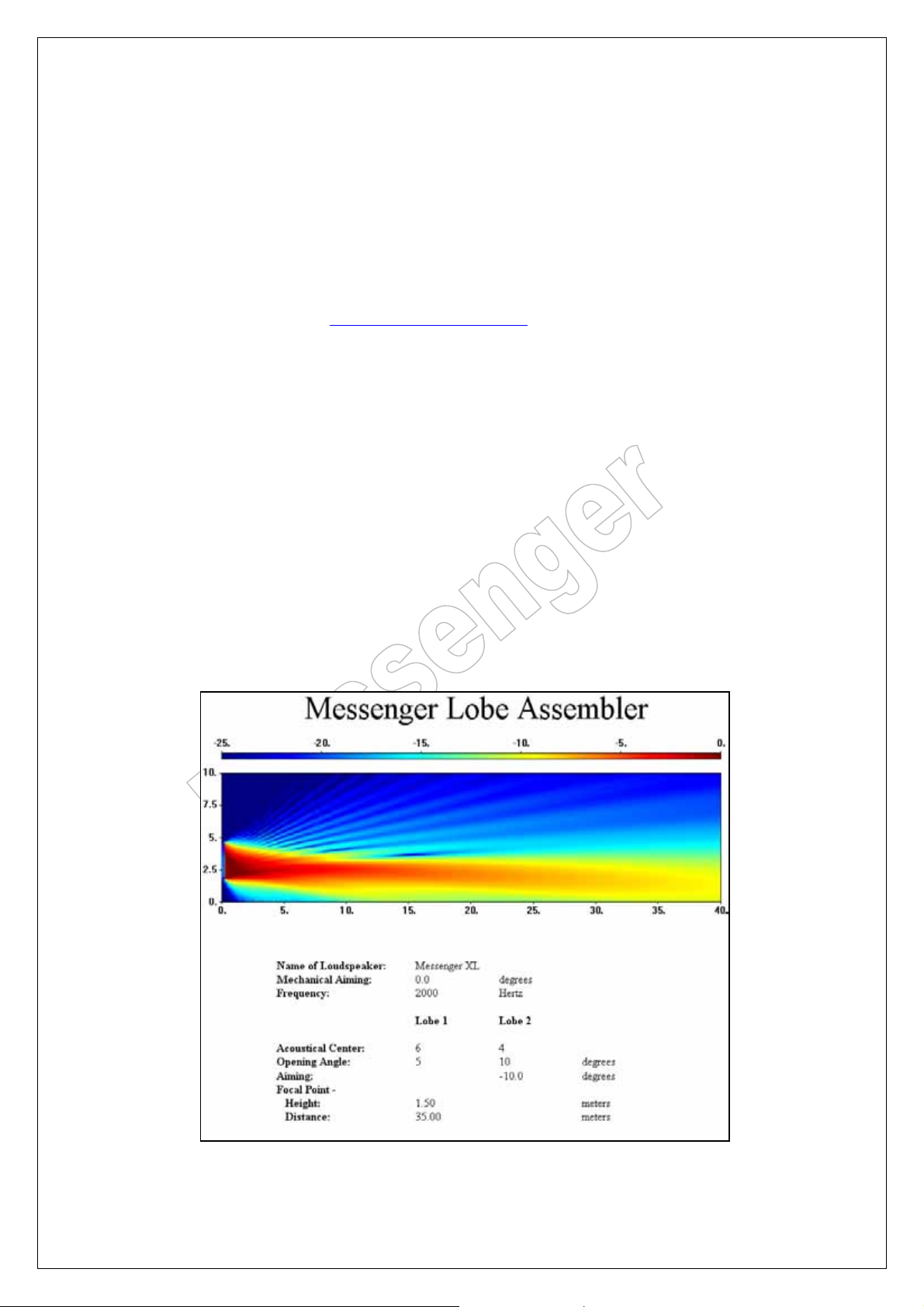
13.1. Project 1:
Typical solution for an average object where the Messengers are hang on a height of 1.80 m,
the first rows are at 5 meter from the Messenger and the last seat at a distance of 30 to 40mt.
Data settings:
Messenger : XL
Mounting height : 1.80
Nearfield row : at 5 mt
Far field row : at 35 mt
Balcony : no
Gain Lobe 1: 3 dB
Gain Lobe 2: -12 dB
Page 34 of 38
Page 35
Messenger Operating Manual
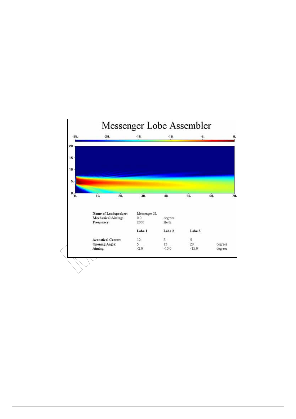
13.2. Project 2:
Typical solution for a shopping centre where the Messenger is also used for emergency
messages and is positioned out of reach of people to become vandal-proof at a height of 3.5
mt. The mall has a depth of 60 mt.
Data settings:
Messenger : Two-L
Mounting height : 3.50
Nearfield : at 5 mt
Far field : at 65 mt
Balcony : no
Gain Lobe 1: 0 dB
Gain Lobe 2: - 6 dB
Gain Lobe 3: - 6 dB
Page 35 of 38
Page 36
Messenger Operating Manual
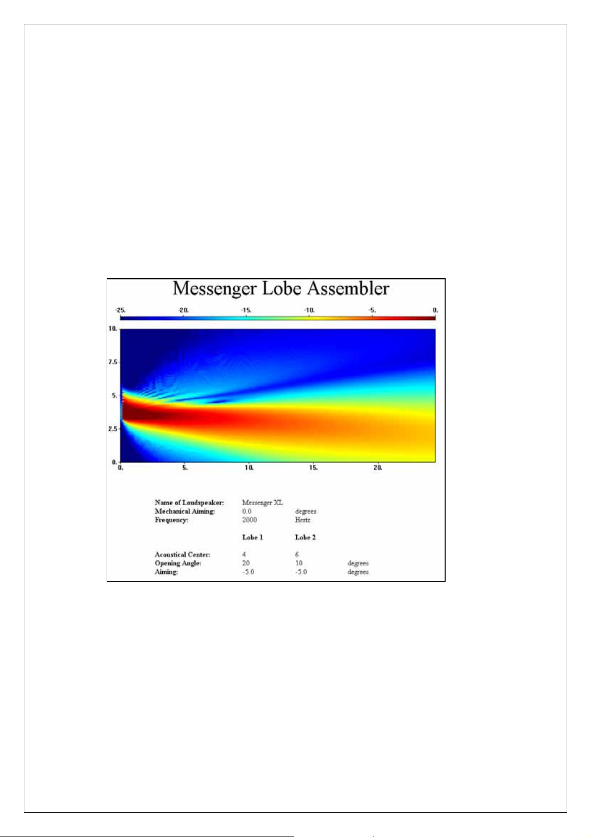
13.3. Project 3
This example describes a system where 4 Messengers XL’s were placed, serving the stales at
the left and right from the stage in a theatre and two for two upper balconies. The trick was to
radiate over the stage avoiding the stage microphones and arrive at the first seats. A second
set of Messengers XL was serving the first and the second balconies with the most remote
seat at 53 mt.
Stales units:
Data settings:
Messenger : XL
Mounting height : 3.17
Nearfield : at 10 mt
Far field : at 26 mt
Balcony : no
Gain Lobe 1: - 4 dB
Gain Lobe 2: - 0 dB
Page 36 of 38
Page 37
Messenger Operating Manual
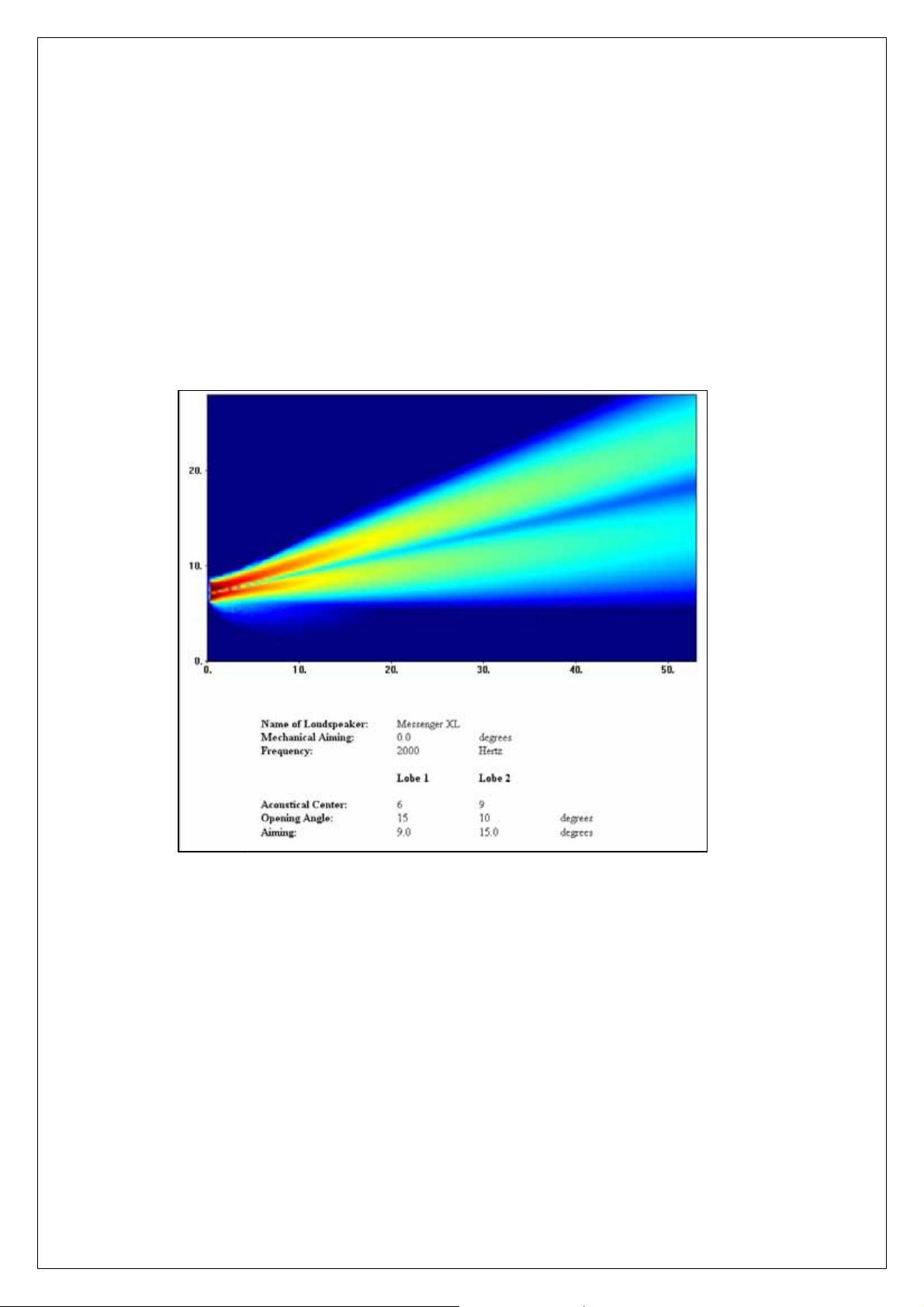
13.4. Project 4
These are the balconies Messengers described in Project 3
Balcony units:
Data settings:
Messenger : XL
Mounting height : 6.27
Nearfield : at 25 mt
Far field : at 53 mt
Balcony : yes
Gain Lobe 1: - 0 dB
Gain Lobe 2: - 2 dB
Page 37 of 38
Page 38

Messenger Operating Manual
ATEÏS International S.A.
Chemin du Vallon, 26
CH-1030 Bussigny-près-Lausanne
SWITZERLAND
Phone: +41 21 881 2510
Fax: +41 21 881 2509
http//www.ateis-international.com
mailto: [email protected]
Page 38 of 38
 Loading...