

Page 1

ATEIS INTERNATIONAL
Version
: EN.1
ECS MANUAL
Full instruction guide for the
Echo Cancellation System
Ateïs International
3/3/2010
Page 2

ECS MANUAL
Version EN.1
CONTENTS
INTRODUCTION ............................................................................................................................4
WELCOME ................................................................................................................................4
PRESENTATION.........................................................................................................................4
PRODUCTS............................................................................................................................4
DEVELOPMENT .....................................................................................................................4
ATEÏS Field of applications ........................................................................................................4
ECS PRESENTATION ......................................................................................................................5
INSTALLATION ..............................................................................................................................6
SYSTEM OVERVIEW ......................................................................................................................7
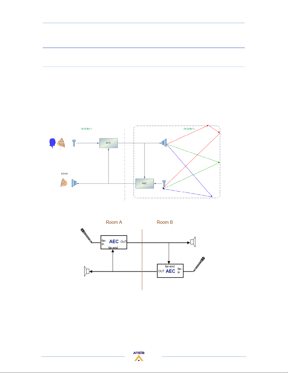
MACHINE..................................................................................................................................7
AUDIO ......................................................................................................................................7
LINKING....................................................................................................................................7
SYSTEM CONFIGURATION.........................................................................................................7
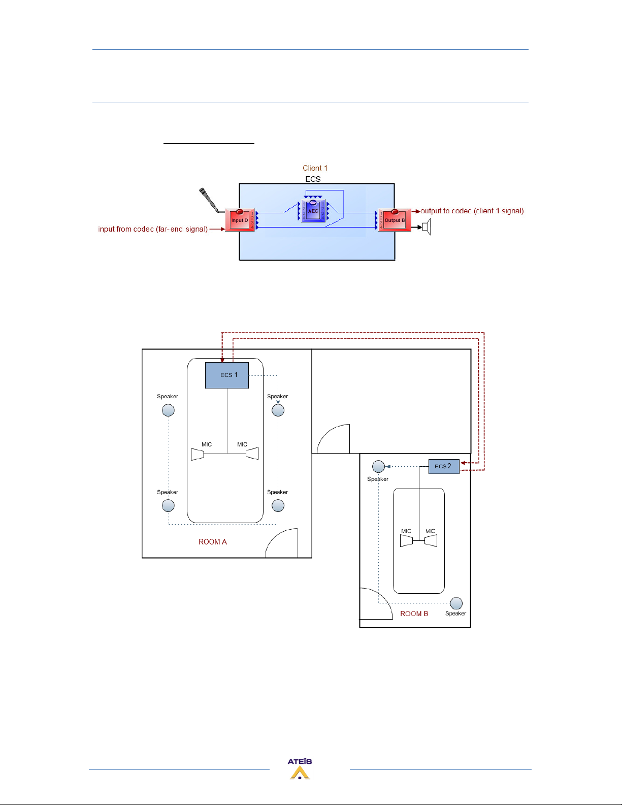
PRESET MANAGEMENT.............................................................................................................8
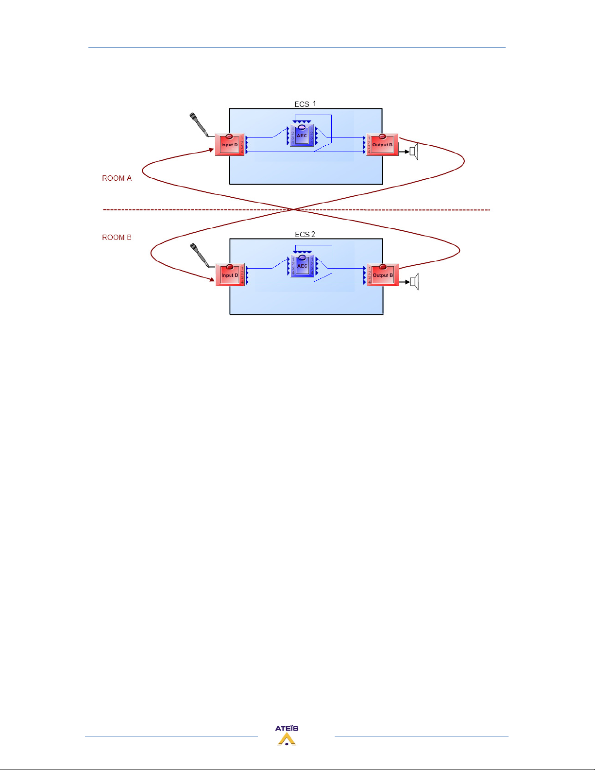
SYSTEM CONTROL.....................................................................................................................8
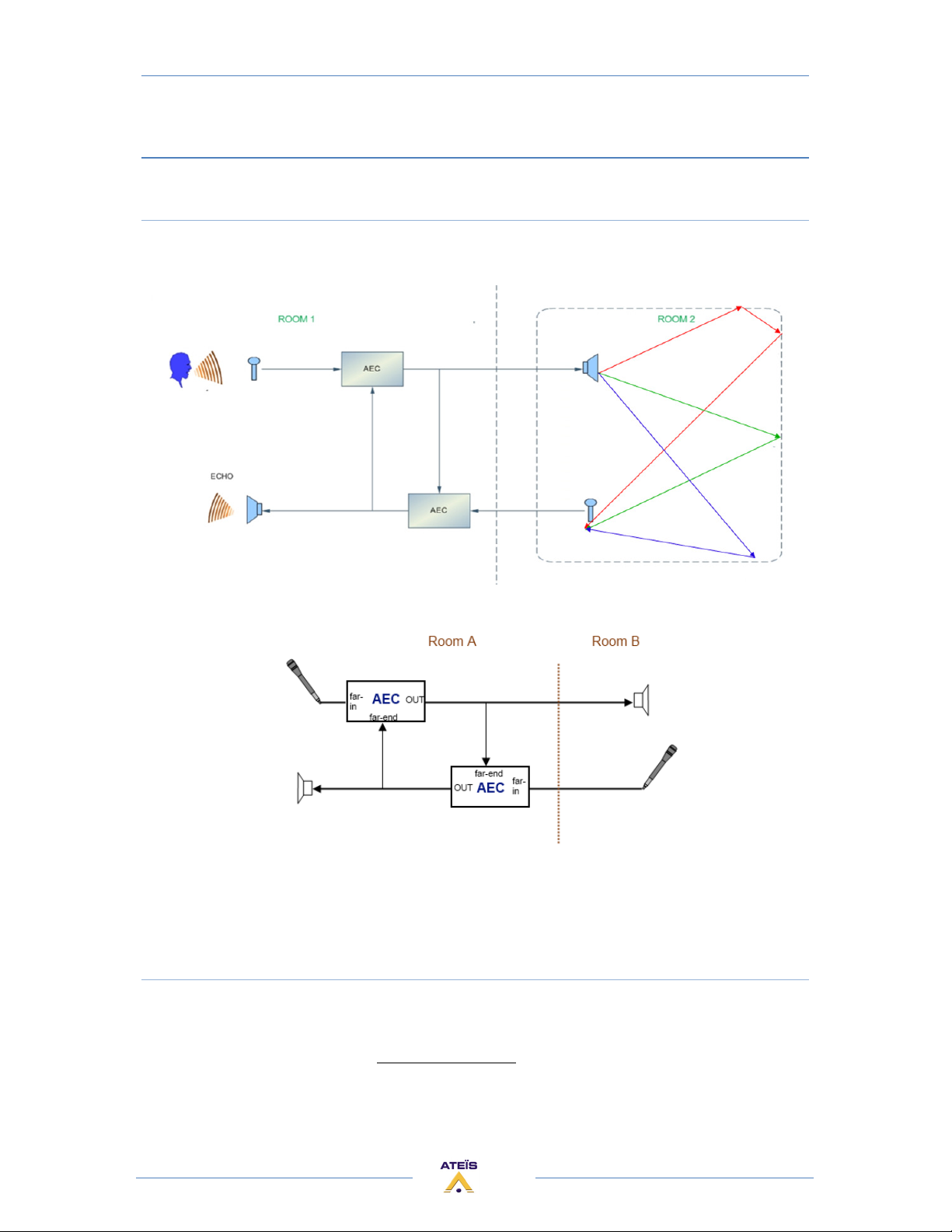
CONNECTION............................................................................................................................8
COMPONENTS ..........................................................................................................................8
SYSTEM.....................................................................................................................................8
OFFLINE PROGRAMMING .........................................................................................................8
FOR YOUR SAFETY ........................................................................................................................9
CONTACTS..................................................................................................................................11
HARDWARE DESCRIPTION ..........................................................................................................12
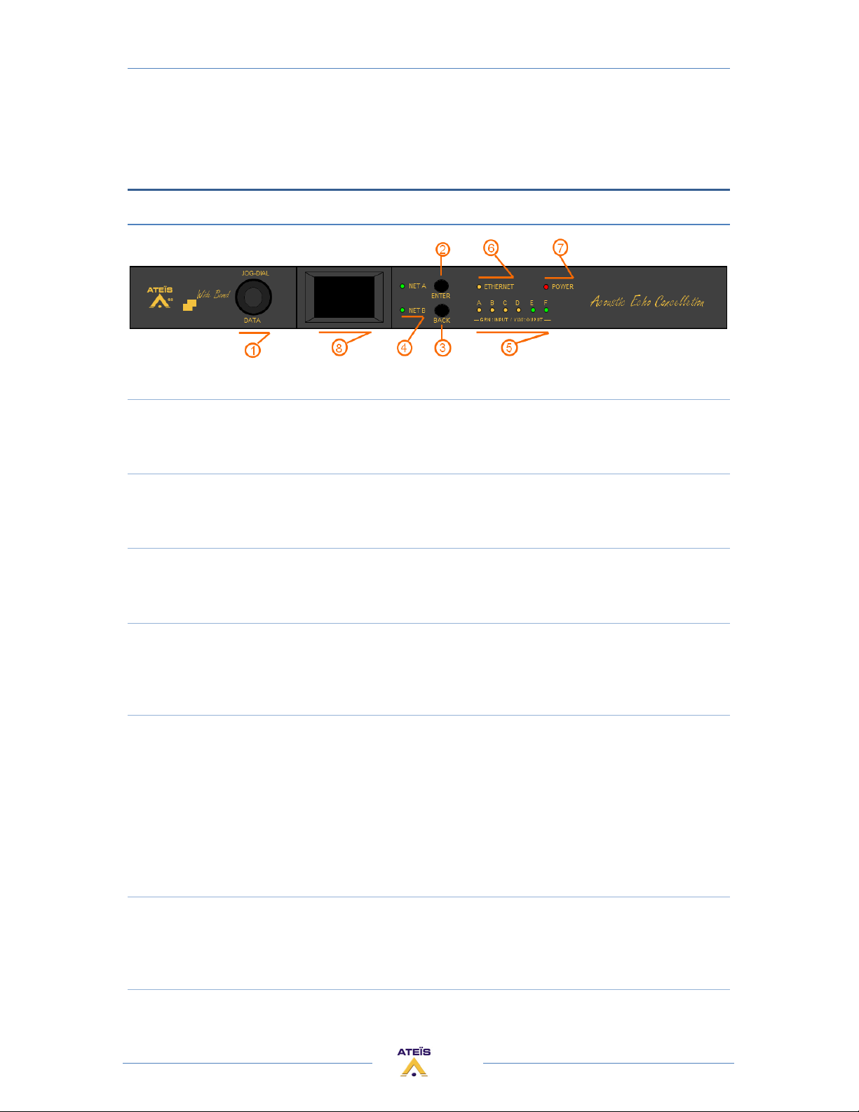
FRONT PANEL .........................................................................................................................12
1) JOG-DIAL / DATA.............................................................................................................12
2) ENTER BUTTON...............................................................................................................12
3) BACK BUTTON.................................................................................................................12
4) NET A / NET B LED...........................................................................................................12
5) CONFIGURABLE AUDIO I/O .............................................................................................12
6) ETHERNET LED ................................................................................................................12
7) POWER LED.....................................................................................................................12
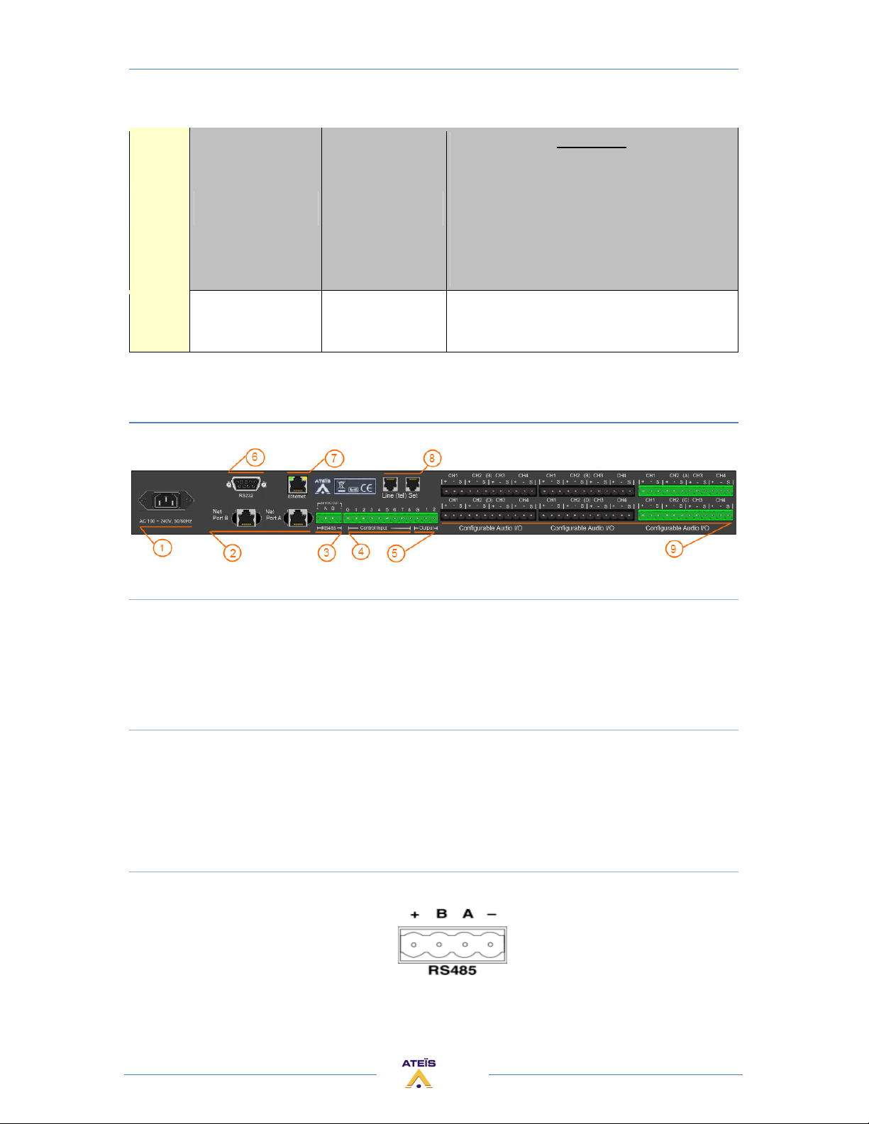
REAR PANEL............................................................................................................................13
1) POWER SECTION.............................................................................................................13
2) LINK CONNECTORS..........................................................................................................13
3) RS485 CONNECTORS.......................................................................................................13
4) CONTROL INPUT CONECTORS .........................................................................................14
5) LOGIC OUTPUTS CONNECTORS .......................................................................................15
6) RS232 CONNECTOR.........................................................................................................15
7) ETHERNET (RJ45) CONNECTOR........................................................................................16
8) TELEPHONE CONNECTOR................................................................................................16
9) AUDIO INPUT/OUTPUT CONNECTOR...............................................................................16
FRONT ACCES (LCD Screen).........................................................................................................17
ACOUSTIC ECHO CANCELLATION (AEC).......................................................................................22
ACOUSTIC ECHO EXPLANATION ..............................................................................................22
ACOUSTIC ECHO CANCELLATION RULES..................................................................................23
AEC WITH TWO DEVICES.........................................................................................................25
Schematic: ..........................................................................................................................25
Design in the ECS: ...............................................................................................................26
AEC WITH ONE DEVICE ...........................................................................................................28
Schematic: ..........................................................................................................................28
2
Page 3

ECS MANUAL
Version EN.1
Design in the ECS: ...............................................................................................................28
AEC WITH CODEC SERVER.......................................................................................................30
Schematic: ..........................................................................................................................30
Design in the ECS ................................................................................................................32
AEC WITH CODEC SERVER AND LOCAL AMPLIFICATION...........................................................33
Schematic: ..........................................................................................................................33
Design in the ECS: ...............................................................................................................33
AEC WITH FULL EXAMPLE (2 mics, 2 lines, local amplification) ................................................34
Schematic: ..........................................................................................................................34
Design in the ECS: ...............................................................................................................35
AEC COMPONENT FUNCTIONS................................................................................................36
AEC Coefficient / Reset .......................................................................................................36
Volume display and control.................................................................................................36
Non Linear Process (NLP) ....................................................................................................37
AEC COMPONENT PARAMETERS.............................................................................................38
AEC SETUP PROCEDURE..........................................................................................................39
TELEPHONE CARD.......................................................................................................................45
Schematic: ..........................................................................................................................45
Design in the ECS : ..............................................................................................................46
TELEPHONE CARD COMPONENT.............................................................................................46
TC Transmit Component .....................................................................................................46
TC Receive Component.......................................................................................................48
LOCAL ECHO SUPPRESSOR ..........................................................................................................49
Schematic: ..........................................................................................................................50
Design in the ECS: ...............................................................................................................50
LOCAL ECHO SUPPRESSOR COMPONENT ................................................................................51
ADDITIONAL DEVICES FOR ECS SYSTEM ......................................................................................52
URC (UNIVERSAL REMOTE CONTROL) .....................................................................................52
PPM........................................................................................................................................52
PPM-SP (stacking paging)........................................................................................................52
RAC (REMOTE ACCESS CONTROL) ...........................................................................................53
JB (JUNCTION BOX).................................................................................................................53
Remote Devices Hardware Connections .....................................................................................54
Connection example for one PPM with JB...............................................................................55
Connection example for several PPMs with JB ........................................................................56
Rj45 pin out ............................................................................................................................57
Junction Box ...........................................................................................................................57
Connect JB to ECS ...............................................................................................................59
Connect URC to ECS with JB ................................................................................................59
Connect URC to ECS ............................................................................................................59
Connect PPM to JB..............................................................................................................60
Connect PPM to ECS ...........................................................................................................60
Connect RAC...........................................................................................................................60
3
Page 4

ECS MANUAL
Version EN.1
INTRODUCTION
WELCOME
Thank you for choosing ATEÏS ECS. We hope you will enjoy using this exciting piece of technology as
much as we enjoy developing and building it.
This manual can be updated at any time without prior notice in order to keep this manual up to date.
In case of errors in this manual or not clear process description, feel free to submit us mistakes,
suggestions or questions by sending an email: [email protected] subject: ECS manual
corrections.
This document intends to be a complete manual and we hope that this Help file will provide you all
information or answers needed. However if you have any questions, feel free to contact us.
PRESENTATION
ATEÏS is a leading supplier of high-quality PA/VA audio equipment with distributors and
subsidiaries in 23 countries throughout Europe, States, Middle East and Asia. Since 1981 we are
manufacturing reliable and high quality loudspeakers, amplifiers, security matrices and other audio
components. Our products are manufactured to IS0 9001 standards and, when possible, meet local
requirements.
With more than twenty years of experience, ATEÏS has quickly established itself as a leading
manufacturer of Public Address, Voice Alarm systems and counter intercoms. The constant growth of
market share in Europe provides confirmation of the quality of ATEÏS’s commercial and technical
approach.
PRODUCTS
The company now offers a full range of sound equipment: microphones, preamplifiers, digital
processors, digital audio matrixes, loud-speaker monitoring systems, amplifiers, etc. ATEÏS designs
and manufactures leading products in the voice alarm systems market which have been certified
EN60849 compliant by the TÜV.
DEVELOPMENT
Thanks to a development team that includes thirty engineers, and to constant investment, we are
able to respond quickly to the demands of our various markets with specific solutions and cutting
edge technology. We have distributors in more than fifteen countries in Europe and the Middle East,
with whom we have carried out major projects. In choosing ATEÏS, you are guaranteed a trustworthy
partner that can be counted on for the long term.
ATEÏS Field of applications
ATEÏS's audio systems have been installed into following markets:
- Railways
- Subways
4
Page 5
ECS MANUAL
Version EN.1
- Airports
- High raise buildings
- Hotels
- Restaurants
- Shopping center and Malls
- Theme parks
- Places of worship
- Stadia
- Museums
- Industrial buildings
- Industrial plants
- Commercial buildings
ECS PRESENTATION
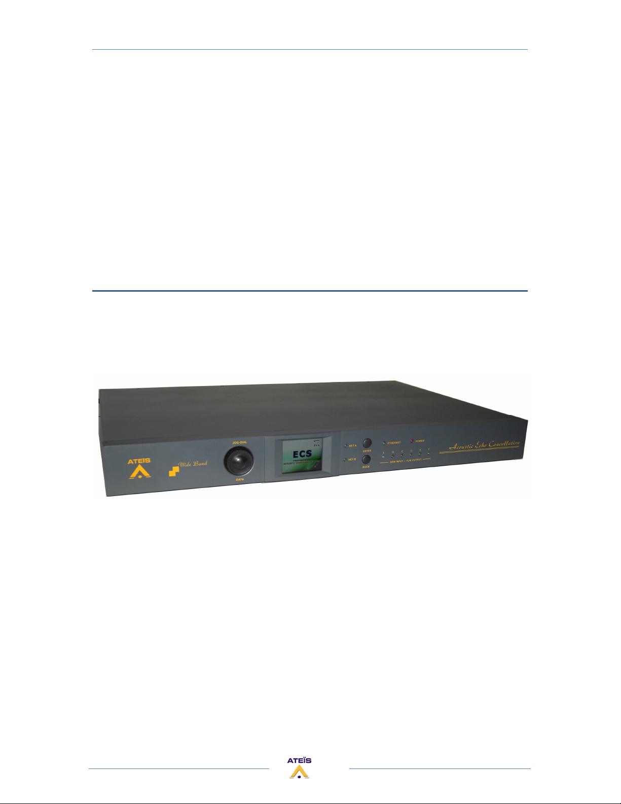
The ATEÏS ECS is the new Ateïs processor which includes the echo cancellation component in more
than general functions of UAPg2 and LAPg2.
Designed for Conference application, the ECS is the new DSP audio Matrix for medium paging
application and multi zone audio routing.
According to its powerful audio numerical signal treatment the ECS can easily be used in an exigent
environment requiring audio quality.
Thanks to its Ethernet port you can easily connect and pilot the ECS through an IP network or direct
from a PC by using RJ-45 connector.
ECS's programming is done through convivial software Ateïs Studio based on graphical Windows®
design environment. The signal path is defined by adding DSP components (Equalizer, Gate,
Compressor, delay...), simply inserted in a clear and easy graphical window by "drag en drop"
operation. You can recreate a complex audio system in a simple 1U space machine. Forget the
addition of machines that required racks and too much long cables in the past.
Once programmed, you can pilot your system through PC, VITY, Crestron or AMX. You can also
disconnect the PC and the networked devices run as a standalone system; however it can be
controlled through a range of controllers (logical TTL Input, logical TTL Output, analogical inputs,
RS485 network). Wall mounted source selectors, smart controllers and programmable paging mikes
are available.
5
Page 6

ECS MANUAL
Version EN.1
INSTALLATION
RACK MOUNTING:
If needed, fit the rack mounting brackets to each side of the ECS by using the 6 pcs Phillips M3X
screws supplied with the package.
SITTING
The ECS takes only a single 19’’ rack space and generates little heat itself. Consider leaving
enough ventilation space above and below the unit. Do not mount the ECS directly above heat
generating devices like power supplies or power amplifiers.
ECS cooling is provided by a fan at the left side of the unit. Be sure to not to block the air vent
holes along the sides of the housing. Normal operation is ensured within a temperature range
between 0°C and 40°C (32 °F to 104 °F).
POWER CONNECTION:
Connect the AC to the mains supply via a power cord. Check your line voltage before plugging in.
The power supply of the ECS accepts AC voltages ranging from 100 V to 240 V, 50/60 Hz. The ECS can
also be powered up from a 24 VDC supply; i. e. backup battery.
6
Page 7
SYSTEM OVERVIEW
MACHINE
ECS MANUAL
Version EN.1
The ECS is made of:
• 6 slots of 4 audio channels
• 8 (0 to 5 VDC) Control inputs either analogue or Logical (contacts)
• 2 logic outputs (Dry contacts)
• RS-232 serial interfacing for third party control
• Ethernet port (RJ-45) TCP/IP based
• RS-485 for connecting ATEÏS remote devices (URC, PPM-SP)
• 90 Mbytes memory Message player (Wave format, 16/24/48kHz, 16bits)
• Devices linked using ATEIS NET
• One microcontroller and one DSP for standalone operation
AUDIO
The ECS unit handles 6 slots of 4 audio channels. Each slot can contain either an input board (A/D
converters) or an output board (D/A converters); this is a factory hardware configuration. You can
choose between them and custom your ECS as you want.
The excellent sonic performance is being achieved by the advanced 24 bit A/D and D/A
converters, together with the 48/96 kHz capable audio processing and the ADSP 21369 (400MHz
SIMD SHARC Core, capable of 2.4 GFLOPS peak performance).
Every single analogue audio input can be software defined for five different sensitivities (input gain
of 0dB, 12dB, 24dB, 40dB or 54dB it means the input device have sensitivities of 0dB, -12dB, -24dB, -40dB or -54dB) and
for 48V phantom power operation. This can be set for each single channel and each machine
independently.
The ECS can contain from 1 to 4 AEC boards. Each one has two ADSP 21363 (333 MHz SIMD
SHARC Core, capable of 2 GFLOPS peak performance). That's need for the AEC treatments.
LINKING
If more inputs or outputs are required, it is possible to digitally link several ECS by using the
Ateïs Net. This one is explained in the Ateïs Studio manual.
SYSTEM CONFIGURATION
To tell the machine what to do with audio and control signals there is a Windows® based
graphical design and operating environment software called Ateïs Studio. With this all-in-one
program you build up the network, design signal processing from a huge library of DSP components
and apply control sources.
The signal path of the ECS is built from virtual elements called 'Components', providing the
functionality of simple preamps, filters, dynamics, delays, or more complex processors like automatic
mixers, crossovers or feedback killer. Their control windows hold all the buttons, faders, knobs,
meters etc. to set the desired values.
7
Page 8

ECS MANUAL
Version EN.1
There is also the AEC component which is particular to the ECS. It is this component which allows
echo cancellation.
After selecting, placing and wiring DSP 'Components', your 'System' will be compiled and sent to
the ECS via TCP/IP Ethernet port.
PRESET MANAGEMENT
The ECS includes two types of presets:
The Sub-Preset presets (Parameter -preset): They enable values of multiple parameters of the
same design, such as levels, gains, EQ, etc. to be restored either from the PC software, the remote
controllers or the control inputs.
The Master presets (Design preset): they enable completely different designs to be restored.
Application examples for this feature are hotel meeting rooms with removable walls.
These 'Master Presets' and 'Sub-Presets' residing in the ECS's memory which can be accessed in
many ways: PC, Logic inputs, Third party.
The limitation depends on memory usage. In Ateïs Studio, there is an indication of percentage
of used memory
SYSTEM CONTROL
Once a 'System' is stored into the ECSs memories, you can disconnect your PC and run it as a
standalone audio network. You can control all parameters like 'Channel Level', 'Master Volume' etc.
from assignable control sources or from front knob. There is a range of control devices built for the
system you can operate. The ECS integrates perfectly into third party control systems like: VITY, AMX,
Audace, Crestron, etc.
CONNECTION
Audio and control connections are made via Euro-block connectors on the rear panel of the
units.
COMPONENTS
Huge library with audio tools for all applications (routing, paging, signal processing, networking,
speaker managing, etc)
SYSTEM
• System design by drag & drop
• DSP design by drag & drop from component library
• Changeable appearance of the control elements
OFFLINE PROGRAMMING
Design and editing of 'DSP designs'
8
Page 9
ECS MANUAL
Version EN.1
FOR YOUR SAFETY
Please follow the instructions in this chapter to get the optimum results from these units.
EXCLUSION OF RESPONSIBILITY
Manufacturer, importer, or dealer shall not be liable for any incidental damages including
personal injury or any other damages caused by improper use or operation of the ECS.
INTERFERENCE
Like all computing devices, the ECS uses high frequency digital circuitry that may cause
interference on radio or television equipment placed close to the unit. The best solution for
problems like this is to relocate the affected parts.
WARNING
• Do not expose the ECS to extreme temperatures, direct sunlight, humidity, or dust, which
could cause fire or electrical shock hazard.
• Keep away water or other liquids from the ECS. Otherwise fire or electrical shock may result.
• Connect the power cord only to an AC outlet of the type stated in this Owner's Manual or as
marked on the unit. Otherwise fire and electrical shock hazard results.
• When disconnecting the power cord from an AC outlet always grab the plug. Never pull the
cord. A damaged power cord is a potential risk of fire and electrical shock hazard.
• Avoid touching power plugs with wet hands. Doing so is a potential electrical shock hazard.
• Take care for correct polarity when operating the ECS from a DC power source. Reversed
polarity may cause damage to the unit or the batteries.
• Avoid placing heavy objects on power cords. A damaged power cord is a fire and electrical
shock hazard.
• Do not cut, scratch, bend, twist, pull, or heat the power cord. A damaged power cord is a fire
and electrical shock hazard. Ask your ATEÏS dealer for replacement.
• Turn off the unit immediately, remove the power cord from the AC outlet and consult your
ATEÏS dealer in any of the following circumstances:
o Smoke, odour, or noise getting out of the unit.
o Foreign objects or liquids get inside the ECS.
o The unit has been dropped or the shell is damaged.
o The power cord is damaged.
If you continue using the ECS, fire and electrical shock may result.
• Do not drop or insert metallic objects or flammable materials into the unit as this may result
in fire and electrical shock.
• Do not remove the ECS s cover, as there are exposed parts inside carrying high voltages that
may cause an electrical shock. Contact your ATEÏS dealer if internal inspection, maintenance,
or repair is necessary.
• Do not try to make any modifications to the ECS. This is a potential fire and electrical shock
hazard.
9
Page 10

ECS MANUAL
Version EN.1
• Avoid the ECS’s ventilation slots to be blocked. Blocking the ventilation slots is a potential fire
hazard.
CAUTION
• To prevent the unit from falling down and causing personal injury and/or property damage,
avoid installing or mounting the unit in unstable locations.
• Leave enough space above and below the unit to provide good ventilation of the ECS. If the
airflow is not adequate, the ECS will heat up inside and may cause a fire.
• Operate the ECS in an environment with a free-air temperature of between 0 °C and 40 °C
(32 °F and 104 °F).
• Turn off all audio equipment when making any connections to the ECS, and make sure to use
adequate cables.
• Do not use benzene, thinner, or chemicals to clean the ECS. Use only a soft, dry cloth.
• If the ECS is moved from a cold place (e.g. overnight in a car) to a warmer environment,
condensation may form inside the unit, which may affect performance. Allow the ECS to
acclimatize before use.
10
Page 11
CONTACTS
ECS MANUAL
Version EN.1
INTERNATIONAL
Sydneystraat 42, 3047BP ROTTERDAM - NETHERLANDS
Fountain Court, 2 Victoria Square, Victoria Street, St. Albans, Hertfordshire, AL1 3TF, UK
Web: http://www.ateis-international.com
Chemin du Dévent, 1024 Ecublens -Switzerland
Web: http://www.ateis-international.com/
Building SEA, room 324, DAFZA, DUBAÏ, United Arab Emirats
Web, contact: http://www.ateis-international.com/
34, avenue de l’Europe, Z.A Font Ratel, CLAIX, FRANCE
Web, contact: http://www.ateis-france.fr/
Industriestrasse 8, D-63801 Kleinostheim, Deutschland
Web: http://www.ateis-germany.de/
Web, contact: http://www.ateis.co.uk/
Ateïs China, 亚提斯(中国)技术服务中心
地址:上海市闵行区吴宝路255号力国大厦610室
Web, contact: http://www.ateis.com.cn
ATEÏS Europe bv
Phone: +31 (0)10 2088690
Fax: +31 (0)10 2088699
Ateïs International S.A.
Phone: +41 (0)21 881 25 10
Fax: +41 (0)21 881 25 09
Mail: [email protected]
Phone: +971 4609 1325/24
Fax: +971 4609 1326
Phone: +33 (0) 4 76 99 26 30
Fax: +33 (0) 4 76 99 26 31
Phone: +49(0)60 27 97 98 85
Fax: +49(0)60 27 97 98 80
Mail: [email protected]
phone: + 44 (0) 8456 521 511
Fax: + 44 (0) 8456 522 527
电话:021-54495191/92
传真 021-54495193
Ateïs Middle East
Ateïs France
Ateïs Germany
Ateïs UK
11
Page 12
ECS MANUAL
Version EN.1
HARDWARE DESCRIPTION
FRONT PANEL
1) JOG-DIAL / DATA
The jog-dial allows navigation in the menu of the ECS screen.
2) ENTER BUTTON
This button is used to enter in a menu or to validate a parameter in the ECS screen.
3) BACK BUTTON
This button is used to go out of a menu or out of a parameter in the ECS screen.
4) NET A / NET B LED
These independent led Light when data are received or sent on the port.
5) CONFIGURABLE AUDIO I/O
Inside the ECS you have 6 audio slots (named A, B, C, D, E and F). Each of these audios slots receives
either 4 audio inputs channels or 4 audio outputs channels. When you switch on the ECS you can see
which kind of audio card is fitted in each slots:
• Green LEDs mean INPUTs
• Yellow LEDs mean OUTPUTs
When a signal passes through an input or an output the corresponding LED will blink.
6) ETHERNET LED
Light when the ECS is connected (on-line) to TCP/IP network.
7) POWER LED
12
Page 13
Lights when the ECS is switched on.
Normal status Standby status
ECS MANUAL
Version EN.1
Error status
-Problem on the Ateïs Net.
-The ECS has no design inside.
-The design inside the ECS does not match with
the physical installation.
-If the link led is off :
The ECS has no input link
Power
LED
The LED grows
bright in green
The LED grows
bright in red
The LED flicks in red and green
REAR PANEL
1) POWER SECTION
Insert provided power cable first into ECS then in the wall power connector.
Power switch:
• | (engaged) = ON;
• O (engaged) = OFF
2) LINK CONNECTORS
If you want to put several ECS in your rack (increase the number of input/output or remote
controllers) simply use straight CAT5 cable to connect “Net Port B” output to the "Net Port A” input
of the next sub-ECS. Close the loop by connecting the last ECS to the first one.
Note: this is not a network but a link: The maximum cable length is 10 meters between two ECS.
3) RS485 CONNECTORS
Here starts the RS485 network (connection for PPM and/or URC):
• Power: + and –
• DATA: A and B
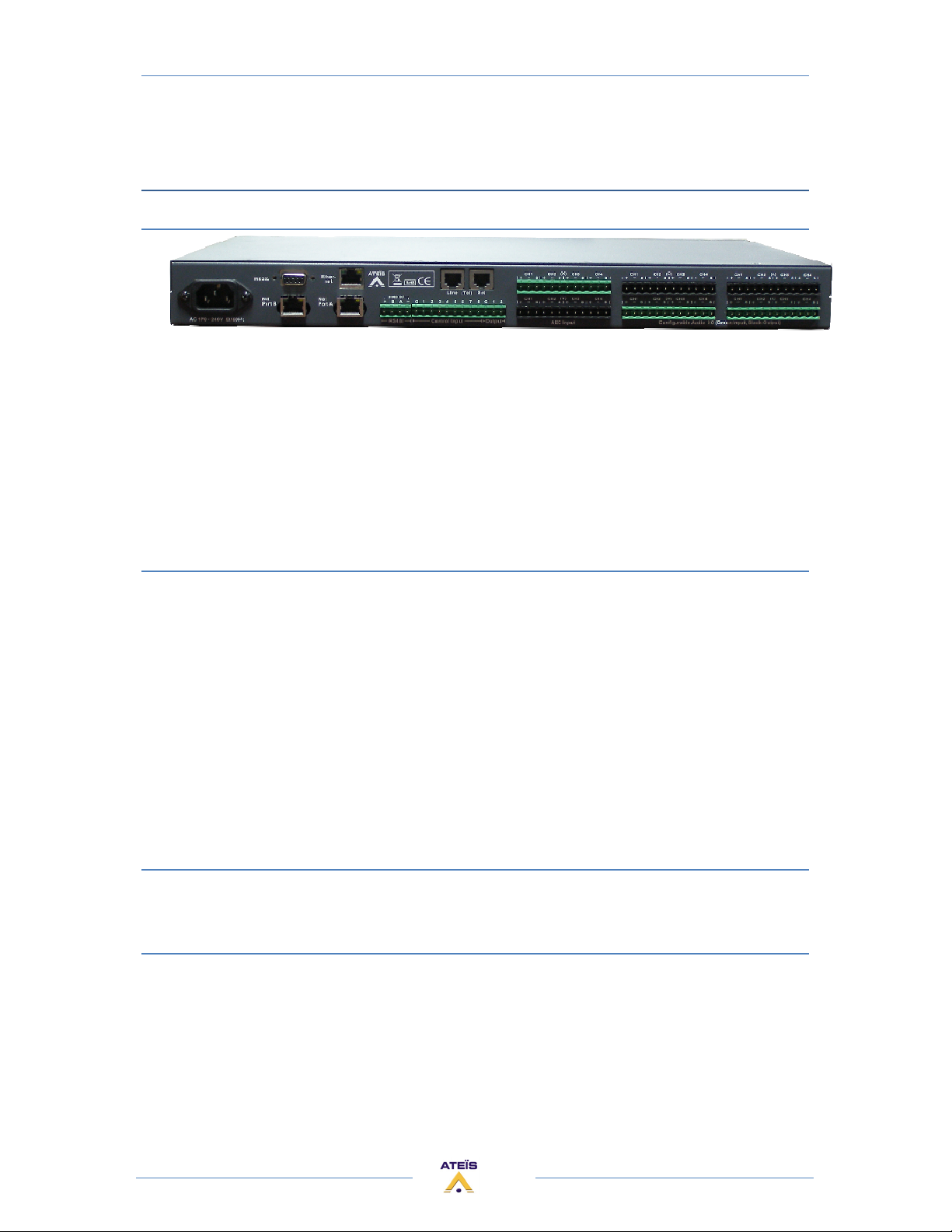
The RS485 port at the rear side of the unit is used for additional units like the URC (Universal Remote
Controller) or the PPM (Programmable Paging Microphone).
13
Page 14
ECS MANUAL
Version EN.1
Note: The maximum cable length depends on the type of cable used and should not exceed 300 m
with standard CAT5.
This restriction is mostly due to supply voltage drops with low wire gauge in longer cable runs
and can be obviated by using external power supplies (Junction Box) or higer diameter cables.
However, we have seen data cable lengths up to 850m working just fine. You will have to put
external power every three remote devices (PPM or URC) or every 300m.
Note: It is recommended to not put more than 8 remote devices (PPM and/or URC) on one ECS. You
can of course use more remote devices (ECS can manage up to 16 PPMs), but this increase the
response time of the devices and you will have to be very carefull in the wiring by adding
external power supply.
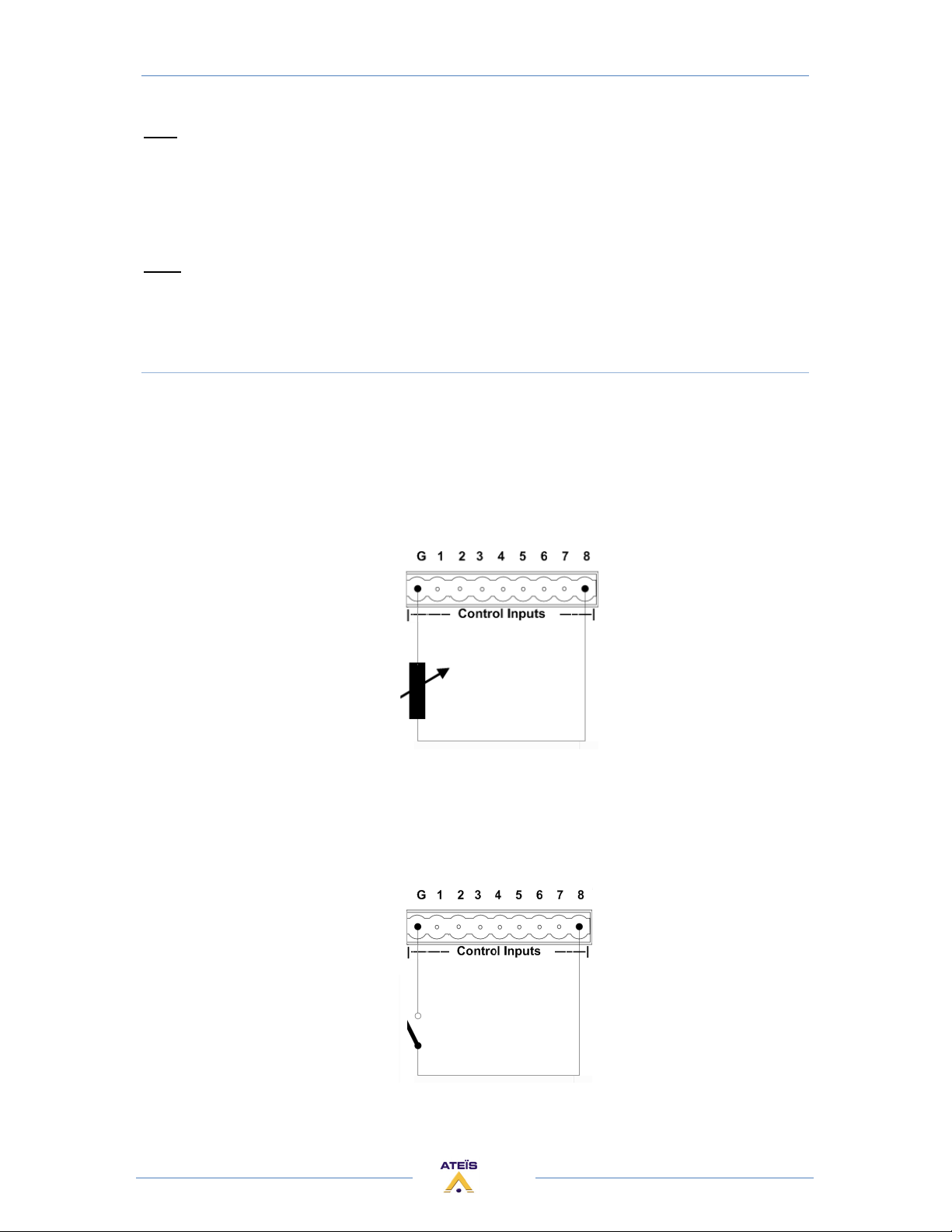
4) CONTROL INPUT CONECTORS
Either connects logical input (TTL IN, dry contact) or analogical input (10 k Ohm potentiometer).
Simply connect the switch or relay or potentiometer between the number (1 and 8) and the G
(ground). The number indicates which control logic channel will be used (when you define the action
of the control input).
If you use control Input as analogue input:
You can connect Remote Controllers RAC5 or RAC8. Or a simple variable resistor (10K) to the
analogue control inputs as follows:
You can reduce the step by putting a 100uF capacitor in parallel across the contact.
If you use control Input as Logic input:
The logic In is momentary activate when the contact is closed.
Simple activation of the TTL inputs can be made like this:
14
Page 15
ECS MANUAL
Version EN.1
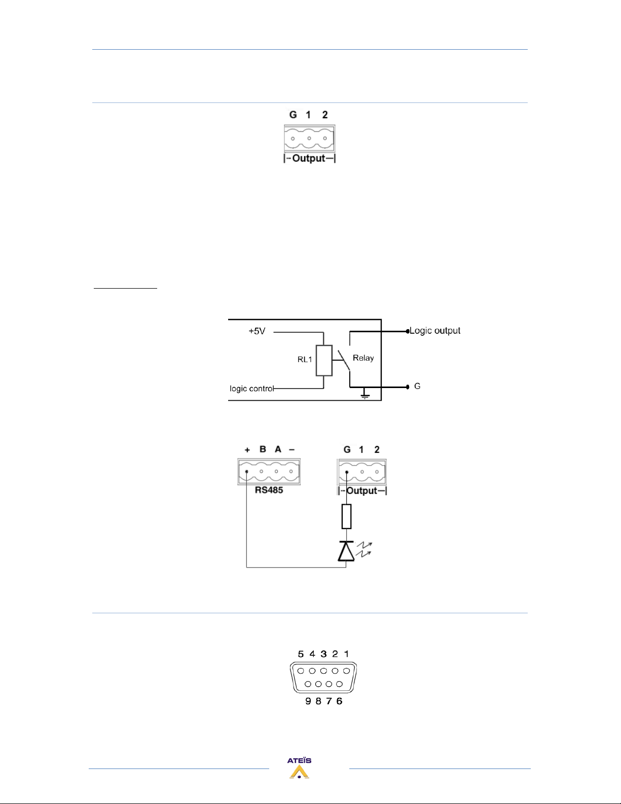
5) LOGIC OUTPUTS CONNECTORS
The Contact closes when the Logic Output is active.
The logic outputs are simple dry contact or relay contact, with a common rail.
The common rail is linked to the ground.
Caution: Do not connect voltage (24V) to the common rail.
No voltage is provided.
Contact rating: (relays EGE type EDR201A0500)
Maximum voltage 100 VDC, Maximum switching current 0.5 amps, Maximum switching power 10VA
If the RS485 bus is unused, then you can easily use the 24V DC output of the ECS to feed 8 LEDS that
each have a 2k2 current limiting resistor.
6) RS232 CONNECTOR
Connect third party device (Crestron, AMX, VITY) to pilot some desired features of your ECS system
by using the Ateïs Third party protocol.
15
Page 16

ECS MANUAL
Version EN.1
At the rear side of the ECS you also find a DB9f connector for RS232 data communication. This port
can be used for transparent RS232 data multipoint communication through the network (for using
with IDA4) or for 3rd party control applications.
Note: RS232 does support cable lengths up to 15 m.
P
Signal Text
i
n
1 CD carrier detect (n.c.)
2 RXD receive data
3 TXD transmit data
4 DTR data terminal ready (n.c.)
5 GND ground
6 DSR data set ready (n.c.)
7 RTS request to send (n.c)
8 CTS clear to send (n.c.)
9 RI ring indicator (n.c.)
(n.c):non connected
7) ETHERNET (RJ45) CONNECTOR
For connecting the ECS in a TCP/IP based network or directly to a computer:
• To load design in a ECS system
• To pilot ECS system
• To monitor ECS system
8) TELEPHONE CONNECTOR
There are two connectors. One is to connect the telephone line. The other is to connect a
physical telephone, allowing you to have a physical interface in more than the software interface.
9) AUDIO INPUT/OUTPUT CONNECTOR
Balanced Audio input or output:
• S = Shield
• + = Hot audio signal
• - = Cold audio signal
Input and output cards have different connector colours:
• BLACK = OUTPUT
• GREEN = INPUT
If you want to use unbalanced signal please connect the Cold (-) pin with the Shield (S) pin.
There is a hardware clip operation on input board over 15dBu.
16
Page 17
ECS MANUAL
Version EN.1
FRONT ACCES (LCD Screen)
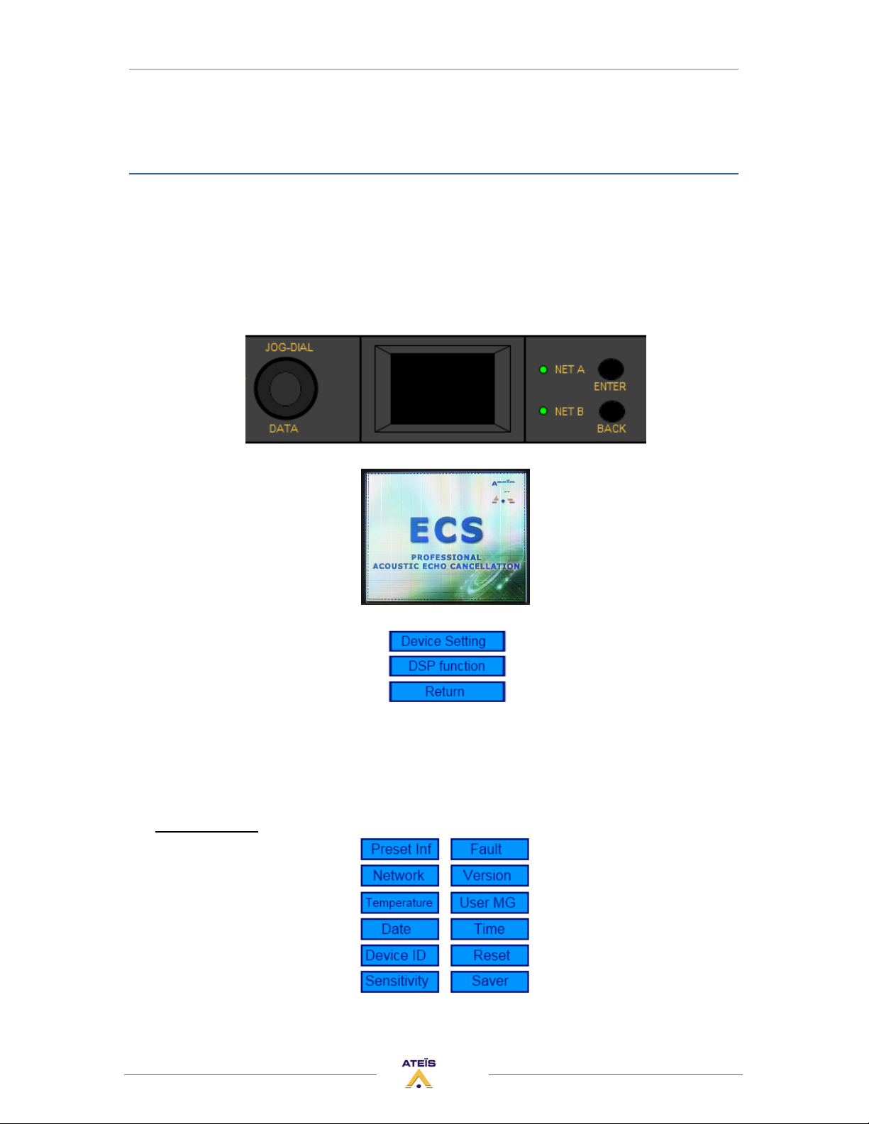
You can get the access to some function and parameters of the ECS, by using the JOG-DIAL, the
ENTER button and the BACK button.
• The JOG-DIAL allows moving in the menu, or modifying a parameter.
• By pushing the ENTER button, you enter in a menu or you select a parameter. If the
screen is on rest, the ENTER button displays the root menu.
• By pushing the BACK button, you get out of a menu or you cancel the selection.
•
On rest the screen displays the ECS logo:
Click on ENTER to displays the root menu:
• Device Setting : enter in the Device Settings
• DSP function : enter in the DSP function
• Return : go back on rest
Use the JOG-DIAL to move in, and click ENTER.
Device Settings >
17
Page 18
ECS MANUAL
Version EN.1
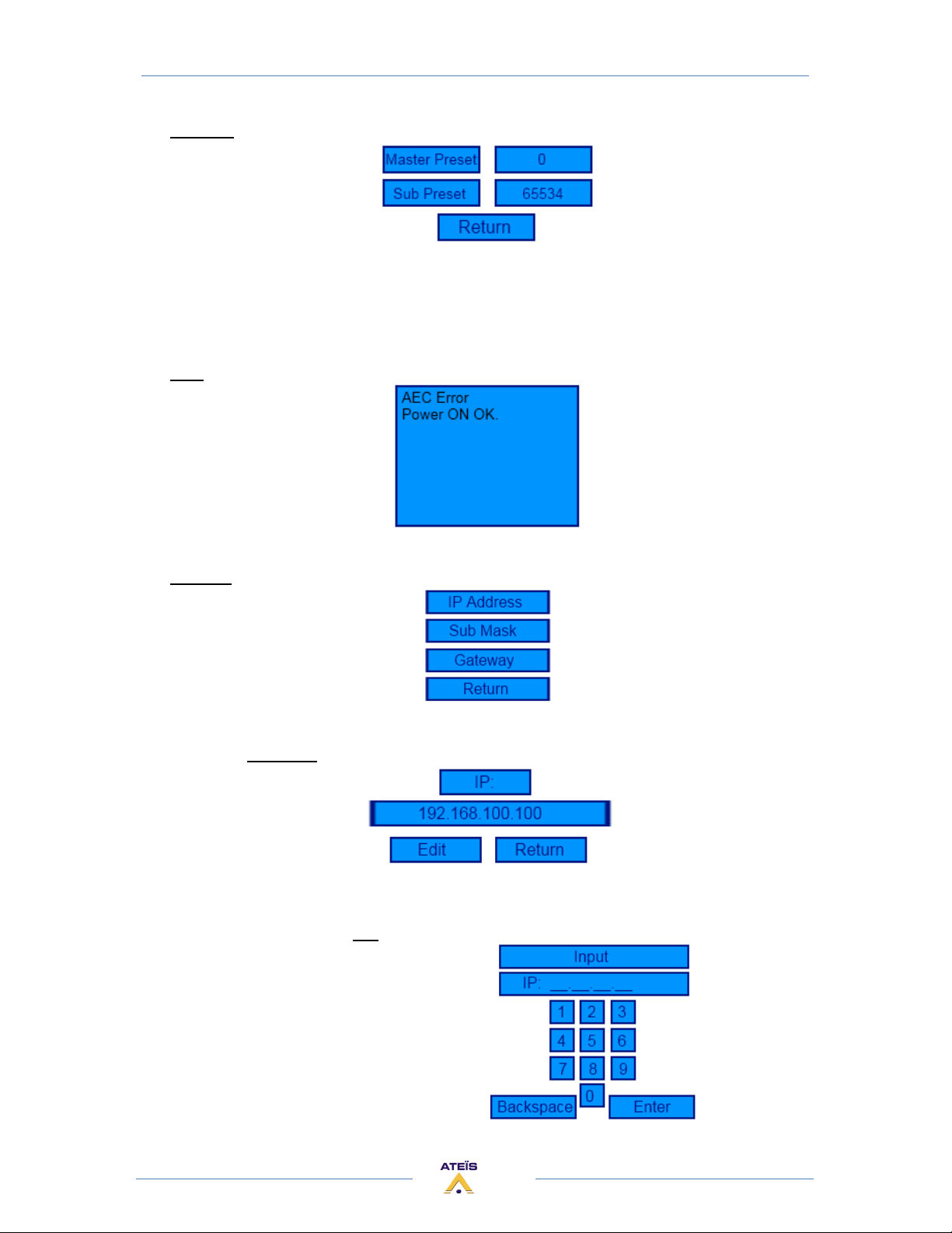
Preset Inf > Information about sub-preset and master-preset
• Master Preset: at the right is displayed the current master-preset number
• Sub Preset: at the right is displayed the current sub-preset number
• Return: go back root menu
Fault > Display the current fault and status of the ECS
Network >
• Return: go back to root menu
IP Address > Here you can set the IP address of the ECS
o Edit : click here to set the IP.
o Return: go back to "Network" menu
Edit > Type the IP address and click [ENTER]
18
Page 19
ECS MANUAL
Version EN.1
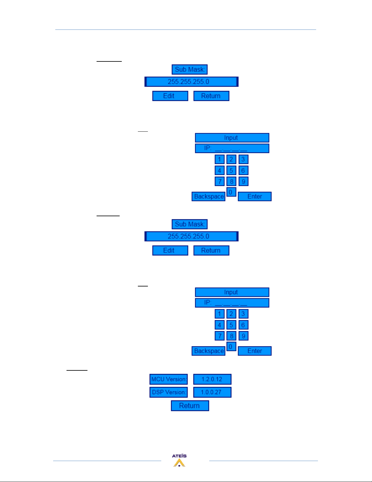
Sub Mask > Here you can set the sub-net mask of the ECS
o Edit: click here to set the mask.
o Return: go back to "Network" menu
Edit > Type the sub-net mask and click [ENTER]
Gateway > Here you can set the gateway of the ECS
o Edit: click here to set gateway IP.
o Return: go back to "Network" menu
Edit > Type the gateway IP and click [ENTER]
Version > Display the current version numbers
• MCU Version : displays the version of the MCU
• DSP Version : displays the version of the DSP
• Return: go back to root menu
19
Page 20
ECS MANUAL
Version EN.1
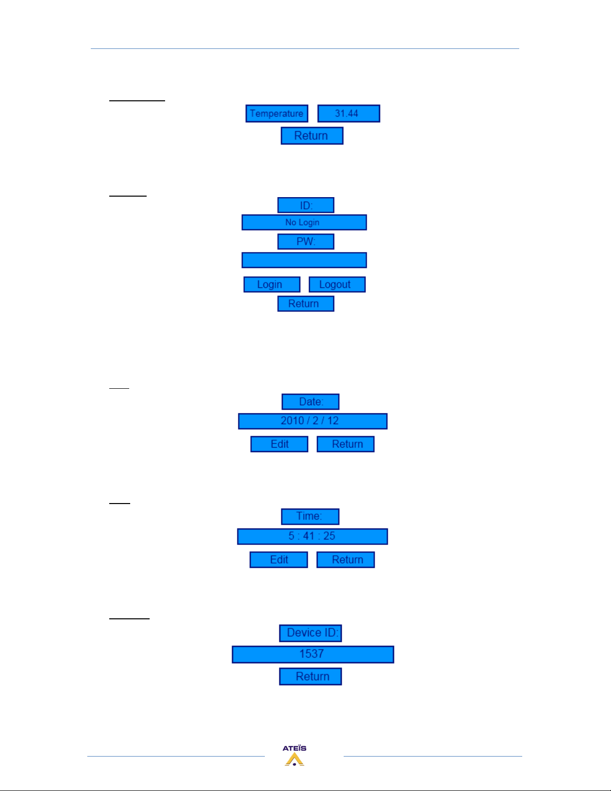
Temperature > Display the temperature of the ECS
• Temperature : displays the current temperature inside the ECS
• Return: go back to root menu
User MG > Allows the user management.
• ID: click here and type the ID.
• PX: click here and type the Password
• Login:
• Logout:
Date >
• Edit: click here to set the date
• Return: go back to Root menu
Time >
• Edit: click here to set the time
• Return: go back to Root menu
Device ID > Display the device ID. It's fixed.
• Return: go back to Root menu
20
Page 21
ECS MANUAL
Version EN.1
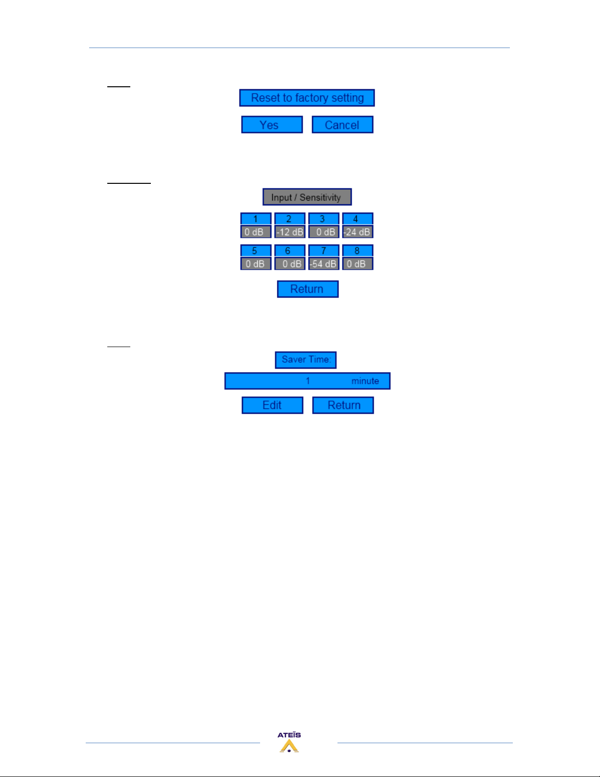
Reset > Allows resetting the device
• Yes: click here to confirm that you want reset the device
• Cancel: click here to not reset the device, and go back to root menu
Sensitivity > Displays the inputs sensitivity of the ECS inputs. (You cannot change them here)
• Return: go back to Root menu
Saver > Here you can choose the saving time.
• Edit: click here to set the saver time
• Return: go back to Root menu
21
Page 22
ECS MANUAL
Version EN.1
ACOUSTIC ECHO CANCELLATION (AEC)
ACOUSTIC ECHO EXPLANATION
In remote conference applications, reflected signals caused by acoustic echo between
microphones and speakers are normal, for example, when two people communicate with each other
in different places.
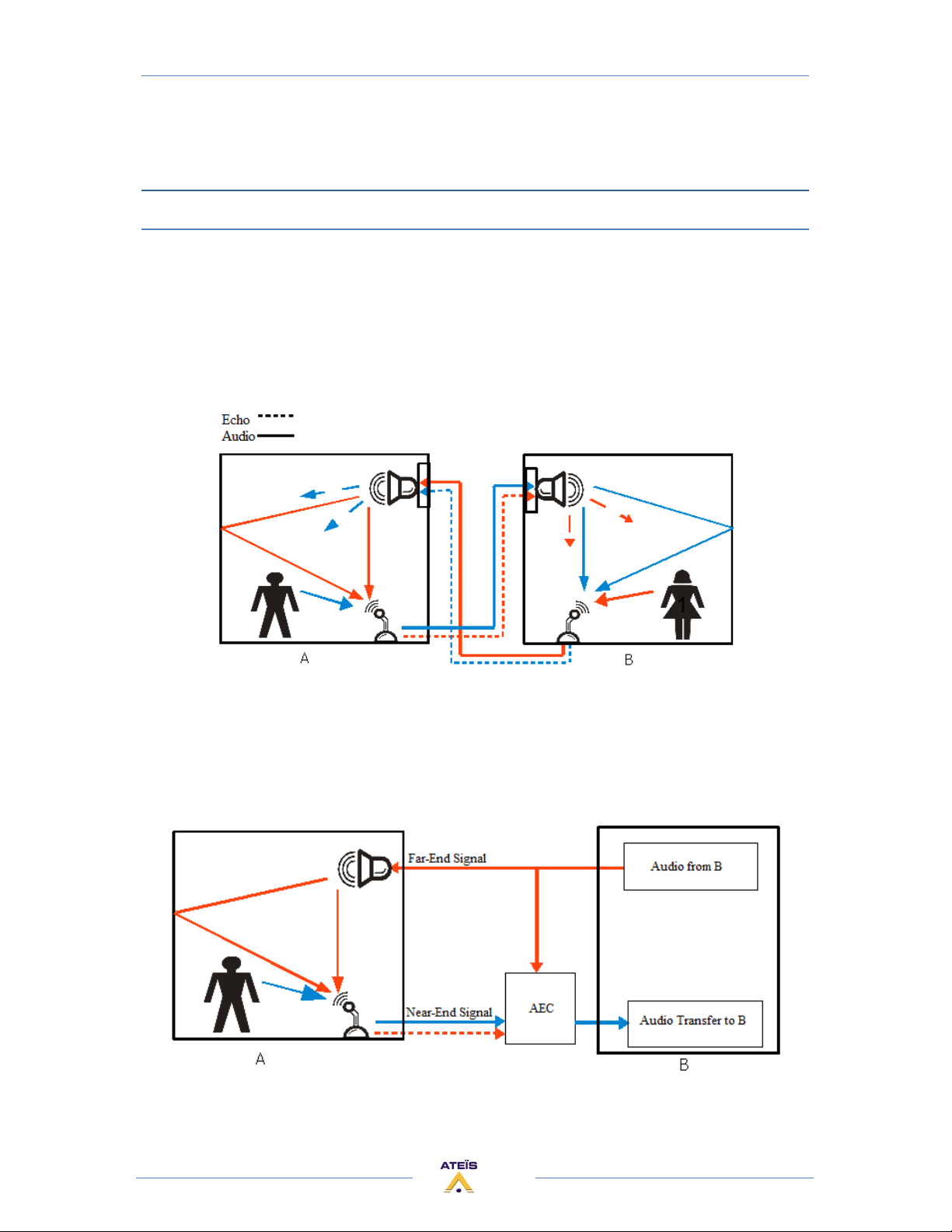
A's voice from the microphone will travel through the speaker in room B and reflect to the
microphone. It would result in acoustic echo. The acoustic echo usually appears when microphones
and speakers are in the same space. It can decrease the quality of the conversation.
The main idea of AEC is to simulate the impulse response of the echo path included space
reflection and time delay. According to this concept, the audio is sampled at the Far-End signal. AEC
applies the sampled signal 180 degrees out of phase with the Near-End signal to eliminate it. If the
simulation is meeting to the real echo signal, the echo will be deleted and not affect the voice of the
user. The following picture aims to eliminate the echo for user B. B will not hear her own voices from
the speaker.
22
Page 23
ECS MANUAL
Version EN.1
The purpose of Ateïs AEC is for cancellation the acoustic echo in the remote conference
applications. The audio quality is wide bandwidth up to 24 kHz. With the Double Talk Detection, the
AEC improves the interactive communication. It can also support the maximum delay time achieved
to 128ms and perform the echo cancellation efficiently.
Depending of the application, different schematic using the AEC can be made. They are explained in
the following chapters.
ACOUSTIC ECHO CANCELLATION RULES
At first we have to define the signal labeling.
Signals Definitions:
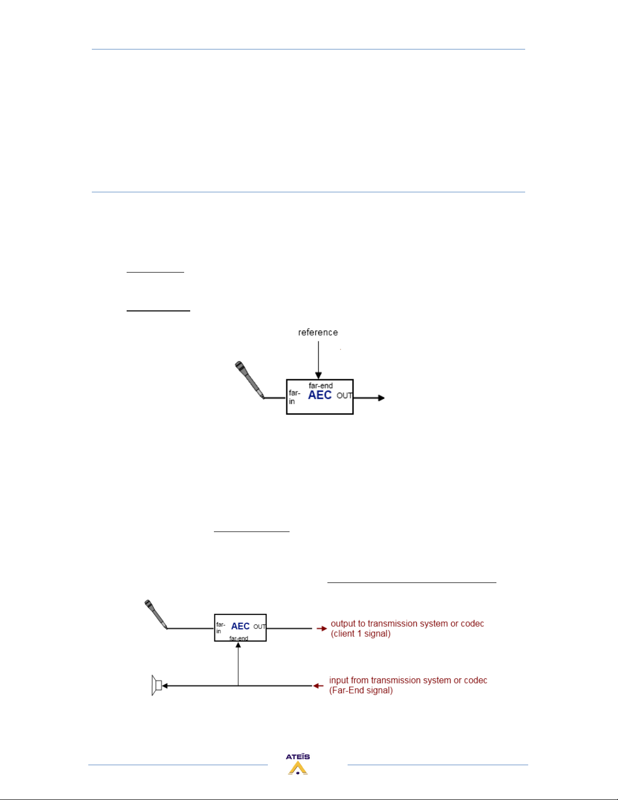
Far-In signal: The audio signal source on which the echo cancellation process is applied.
Generally it's the microphone.
Far-End signal: The audio signal used as reference for the echo cancellation process.
AEC Rules:
Microphones:
Every microphone has to use the AEC before to be sent to the transmission through a mixer if
necessary.
Each microphone needs one AEC channels.
The reference of these AEC channels is the Far-End signal after the AEC treatment.
After proper adjustment of the level (in the input component, and in the mixer) the volume
control of the microphone has to be done with the Near-End Volume parameter of the AEC
component.
23
Page 24
ECS MANUAL
Version EN.1
Audio lines:
If there are audio lines (like CD/DVD/Radio, etc) in more than the microphones, they don't need
to pass through an AEC.
They are directly sent to the transmission and the local amplification through mixer if necessary.
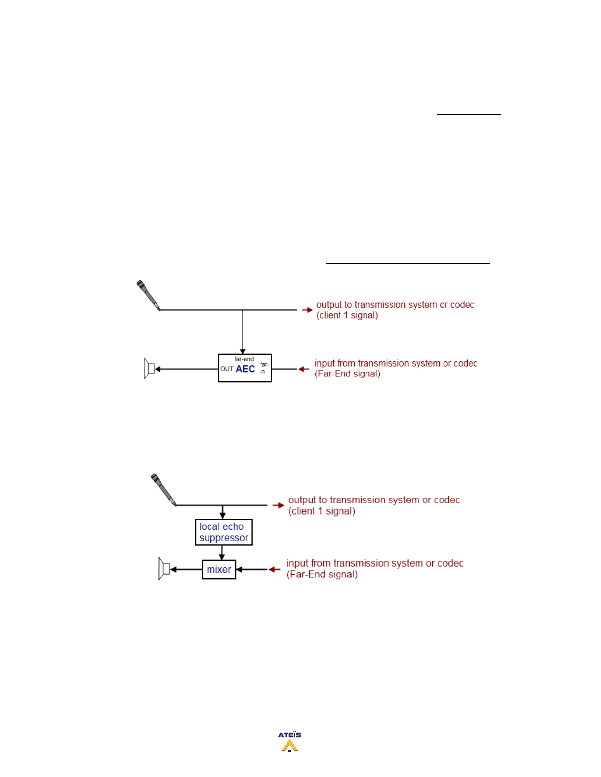
Far-End signal:
If the transmission system use a codec server, then the Far-End signal must be treated on one
AEC channel.
The reference of this AEC channels is the mixed signal of all the local audio sources (output of the
local mixer).
After proper adjustment of the level (in the input component, and in the mixer) the volume
control of the Far-End signal has to be done with the Near-End Volume parameter of the AEC
component.
Local amplification:
If there is a local amplification, then each microphone has to pass through a local echo
suppressor before to be sent to the local amplification.
24
Page 25
ECS MANUAL
Version EN.1
AEC WITH TWO DEVICES
Schematic:
In a system without video codec, each side receives the incoming signal called "far-end",
coming from the other side. Without AEC, this signal contains the audio sources of the other side
(microphones, and maybe PC, DVD, etc) and the echo due to the acoustic reflections on the other
side.
The idea of the AEC is to send a proper signal to the other side.
The AEC simulates the local reflections, and removes them from the signal to be sent.
The AEC component modifies the signal of the local microphone by using the far-end signal as
reference.
This is an example of a standard point to point system:
On the both sides, there is an AEC component on the microphones, in order to send a proper
signal to the other side. The reference signal of the AEC is the signal coming from the other side,
called far-end signal.
25
Page 26
ECS MANUAL
Version EN.1
Design in the ECS:
Regarding the schematic of a point to point system, here is the corresponding design which must
be created with Ateïs Studio software.
With two ECS, the same configuration is stored into each ECS. There are linked together with
two audio signals in the both directions.
26
Page 27
ECS MANUAL
Version EN.1
The complete system with two ECS is linked like this:
27
Page 28
ECS MANUAL
Version EN.1
AEC WITH ONE DEVICE
Schematic:
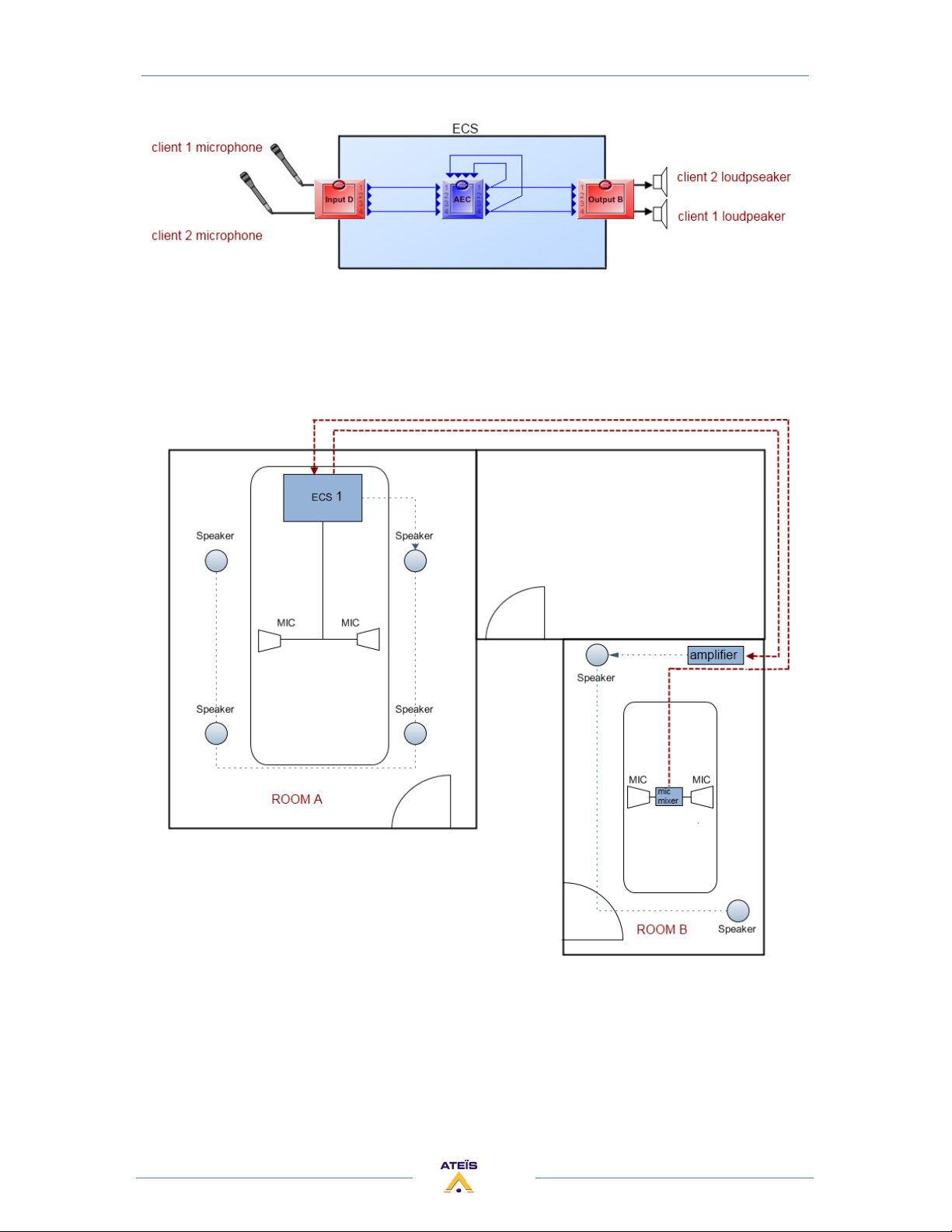
The only difference with the previous chapter, is that here the both AEC components are in the same
ECS.
The schematic is the same, only the room separation has been moved:
There is an AEC component on the both microphones, in order to send a proper signal to the
other side. The reference signal of the AEC is the signal coming from the other side, called far-end
signal.
Design in the ECS:
Regarding the schematic of a point to point system, here is the corresponding design using one
ECS device. It must be created with Ateïs Studio software.
28
Page 29
ECS MANUAL
Version EN.1
With one ECS device, the both configuration are mixed in one design. The signal coming from
the remote room B contain the audio source of the room B, without AEC treatment. The signal sent
from room A has to be amplified and send to the loudspeakers.
29
Page 30
ECS MANUAL
Version EN.1
AEC WITH CODEC SERVER
Schematic:
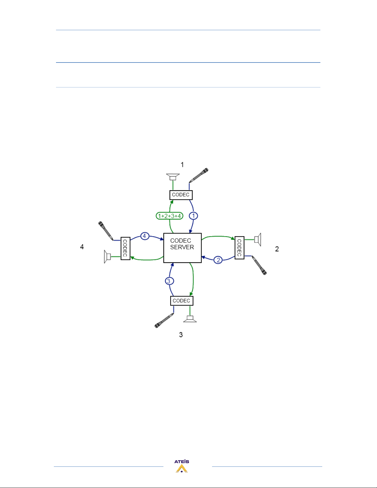
As internet doesn't provide the multi-cast, the most of time, a multi-point conference system
use a video codec server. Each client of this system sends its audio signal to the video codec server.
The video codec server mixes all the received signals in one and sends it to each client of the
system. That means that each the clients receive the audio signal of every client and also its own
signal. It's done like this because otherwise it would take too much process time to send only each
signal to its target.
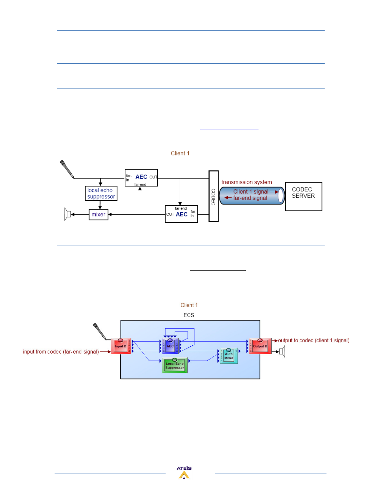
In this following schematic you can that the Client 1 send its signal to the codec server and
receive a mixed signal of the client signal 2,3 and 4, including its own signal 1.
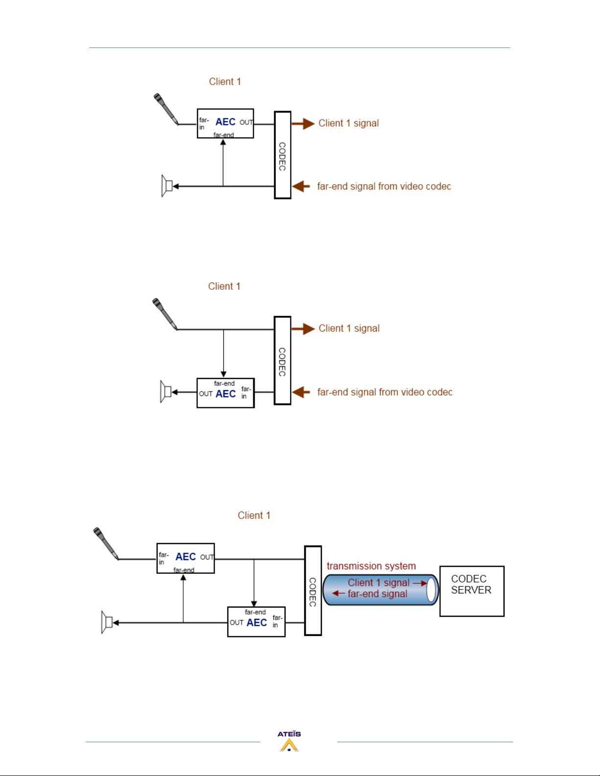
The first using of the AEC is to send a proper signal to the codec server. It simulates the local
reflections, and removes them from the signal to be sent.
The AEC component modifies the signal of the local microphone by using the far-end signal as
reference.
30
Page 31
ECS MANUAL
Version EN.1
As each client receives its own signal (mixed with the others) then each client has to use an
AEC to remove its own signal from the received signal, called "far-end". This is the second using of
the AEC.
In a system with video codec, each client has to send a proper signal to the video codec and
also to remove its own signal from the incoming signal far-end.
The following schematic includes all the required functions decrypted above on a client side
for a system with video codec.
31
Page 32
ECS MANUAL
Version EN.1
Design in the ECS
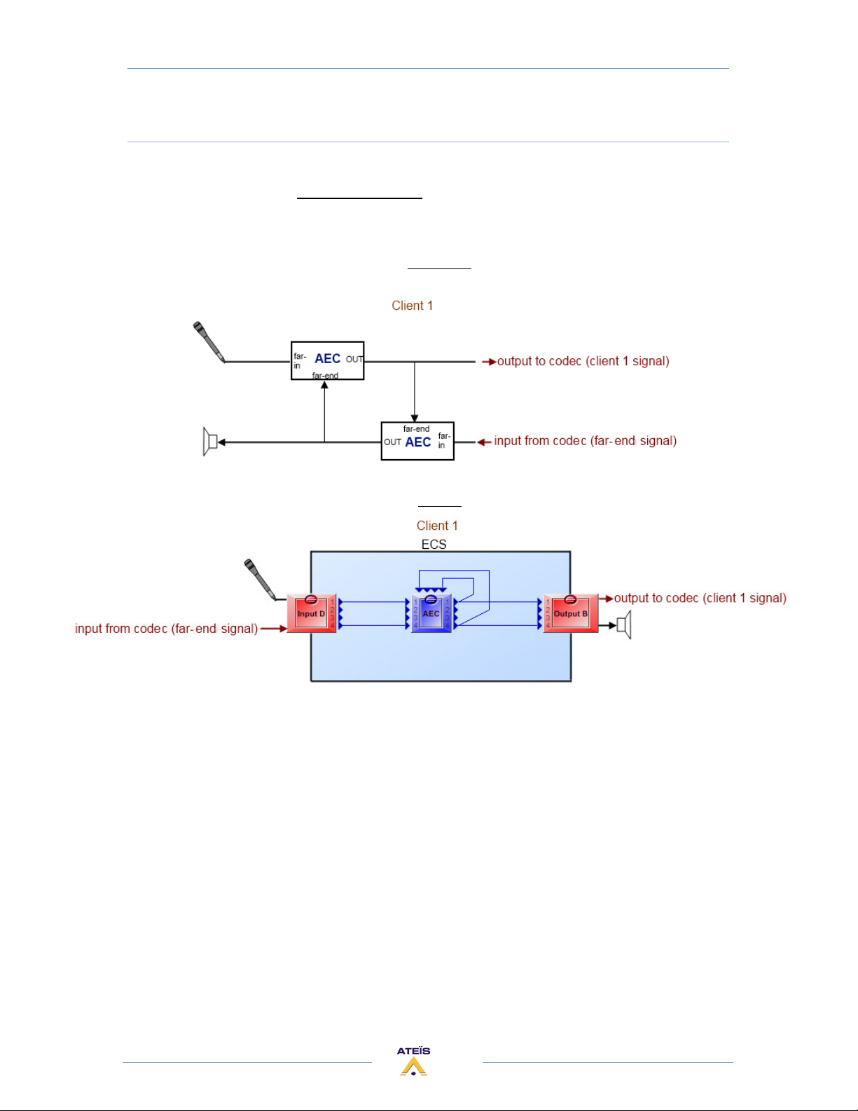
Regarding the schematic of a system using a codec server, here is the corresponding design
which must be created with Ateïs Studio software.
The AEC component provides four independent channels. As we need one channel for each
microphones signal (if there are several local microphones) and one for the far-end signal, the using
of one AEC component is enough.
Schematic:
Design:
It's not easy at first sight, but this design is exactly corresponding to the schematic.
The AEC channel 1, linked to the local microphone use the far-end signal as reference.
The AEC channel 2, linked to the local loudspeaker use the microphone signal (far-in) as reference.
32
Page 33
ECS MANUAL
Version EN.1
AEC WITH CODEC SERVER AND LOCAL AMPLIFICATION
Schematic:
With the AEC, the local reflexions are removed on the signal sent to the codec server.
If the client wants to hear its own microphone signal by using a loudspeaker (and of course an
amplifier), then in order to avoid the local echo reflexion on the local loudspeaker, it is needed to use
also the local echo suppressor component (please see Local Echo Suppressor chapter for detail about
this component).
Design in the ECS:
Regarding the schematic of a system using a codec server and a local amplification, here is the
corresponding design which must be created with Ateïs Studio software.
The AEC component provides four independent channels. As we need one channel for each
microphones signal (if there are several local microphones) and one for the far-end signal, the using
of one AEC component is enough.
33
Page 34
ECS MANUAL
Version EN.1
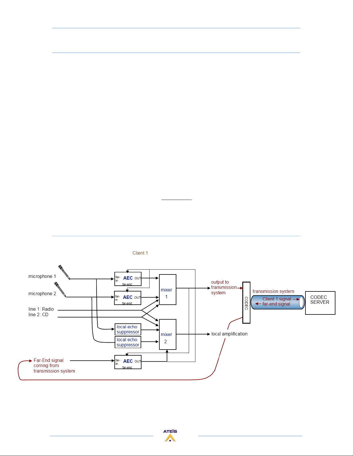
AEC WITH FULL EXAMPLE (2 mics, 2 lines, local amplification)
In this example we include 2 microphones and 2 audio sources (Radio and CD) in a system with codec
server.
Microphones:
Every microphone has to use the AEC before to be sent to the mixer 1 for the transmission. One
microphone needs one AEC channels.
The reference of these AEC channels is the Far-End signal after the AEC treatment.
If there is a local amplification, each microphone has to use a local echo suppressor before to be
sent to the mixer 2 for the local amplification.
Audio line:
The audio sources which are not microphones don't need use AEC.
They are directly sent to the mixer1 and 2, for the transmission and the local amplification.
Far-End signal:
If the transmission system use a codec server, then the Far-End signal has to use one AEC
channel.
The reference of this AEC channels is the mixed signal of all the local audio sources (output of
mixer 1).
Schematic:
As the AEC component contains four channels, all these three AEC modules (for mic 1, mic 2 and
far-end signal) are in one AEC component.
34
Page 35
ECS MANUAL
Version EN.1
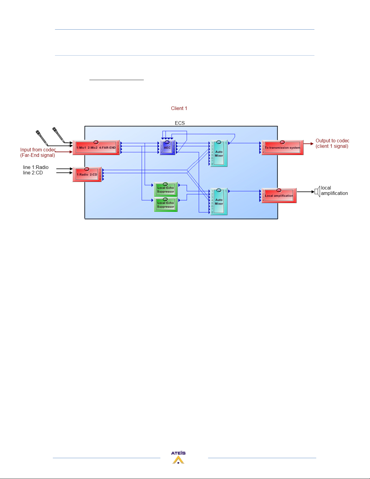
Design in the ECS:
Regarding the complete schematic above, here is the corresponding design which must be
created with Ateïs Studio software.
The AEC component provides four independent channels. As we need one channel for each
microphones signal and one for the far-end signal, the using of one AEC component is enough.
35
Page 36
ECS MANUAL
Version EN.1
AEC COMPONENT FUNCTIONS
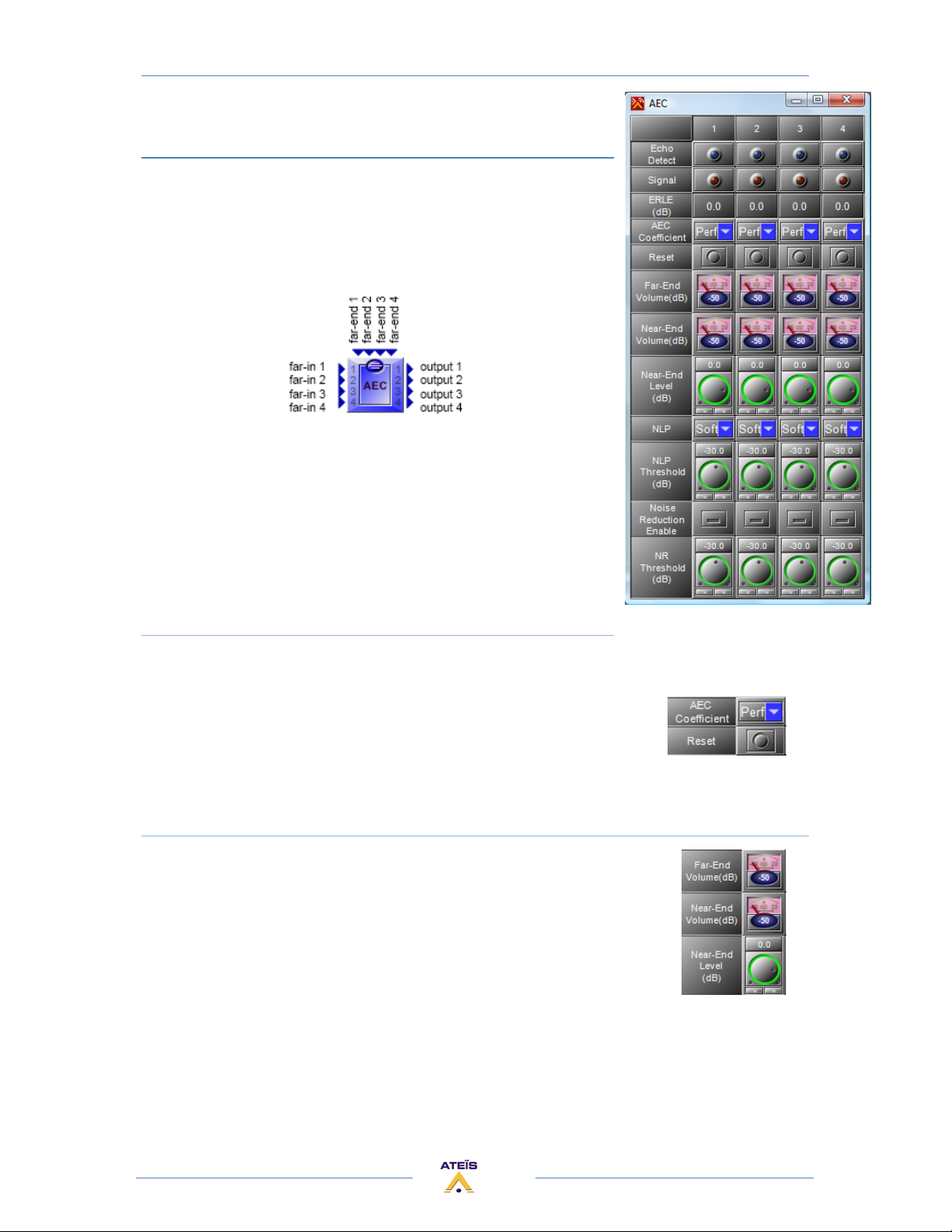
The AEC component provides four fully independent channels.
On the component, each channel has one input called "far-in", one
output, and one reference called "far-end". The far-end signal will be
removed of the far-in signal, in order to send a proper signal to the
other room.
AEC Coefficient / Reset
On each channel you can independently activate the echo cancellation process by setting the
"AEC Coefficient" parameter on "Perform". You can also let it working without
the process activates, by keeping the AEC coefficient by choosing "Hold". Of
course, you can deactivate it on "Off".
The reset button is used to reset the AEC coefficient.
Volume display and control
The far-end volume and near-end volume vu-meters display respectively the
far-end and near-end volume level.
If you want to modify the volume of a source (near-end inputs), then you have
to use the "Near-End Level" knobs in the AEC component. When the system is
properly adjusted, it is not advised to change the volume by using another
parameter than this one.
36
Page 37
ECS MANUAL
Version EN.1
Non Linear Process (NLP)
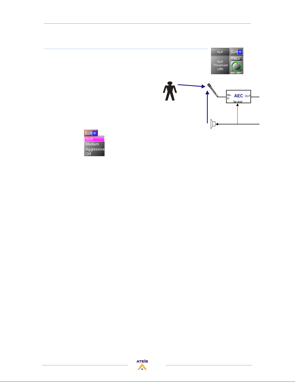
The microphone captures the sound coming from the loudspeaker and also
the speaker's voice.
If on the microphone capsule, the sound pressure
level of the loudspeaker sound is near of the sound
pressure level of the speaker's voice, then the AEC
component won't be able to recognize them. In this
case the AEC process is stopped and the non-linear
process is activated.
All you have to do is to choose the type of the nonlinear process, soft, medium, aggressive or off.
The NLP threshold parameter is not available, the threshold is now automatically set.
37
Page 38
ECS MANUAL
Version EN.1
AEC COMPONENT PARAMETERS
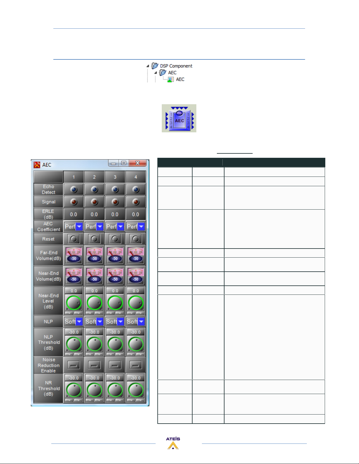
This component is used to avoid reflected signals caused by acoustic echo between microphones and
speakers, in remote conference applications.
The control window of the "AEC" module
is opened by a double click on the icon in the
DESIGN AREA and appears like this: AEC Parameters
Parameter Range Comment
Echo Detect led This led lit when an echo is detected.
Signal led This led lit when an audio signal is detected.
ERLE (dB) Echo Return Loss Enhancement.
The decrement of echo, it indicates the quality
of the AEC.
AEC Coefficient Selector:
Perform,
Bypass, Hold
Reset Button Reset the echo cancellation on the channel
Far-End
Volume
Near-End
Volume (dB)
Near-End Level -90 to 20 (dB) volume adjustment of the near end audio signal
NLP Selector:
NLP Threshold
(dB)
Noise
Reduction
Enable
NR Threshold -90 to 20 (dB)
Vu-meter
(dB)
Vu-meter
(dB)
Soft,
Medium,
Aggressive,
Off
-90 to 20 (dB) The threshold value of the Nonlinear Process.
Button Enable the noise gate
Function supplied for AEC controlled status. It
offers 4 functions:
• Perform: turn on the AEC function
• Bypass: turn off the AEC function
• Hold: hold the parameters of the echo
coefficient
Audio volume of the Far-end audio signal.
Audio volume of the Near-end audio signal.
The purpose is to suppress the remain echo in
complex environment.
It offers four functions:
• off: NLP function off
• soft: weak intensity of remain
echo suppression.
• medium: medium intensity of
remain echo suppression.
• aggressive:aggressive intensity of
remain echo
suppression.
Threshold of the noise gate
NonLinear Process.
38
Page 39
ECS MANUAL
Version EN.1
AEC SETUP PROCEDURE
The design must be stored into the ECS, and your PC on which Ateïs Studio is running must be
On-line (live) with the ECS. Now you can start the setup procedure.
You can have different kind of ECS use, but the setup procedure idea is the same for all.
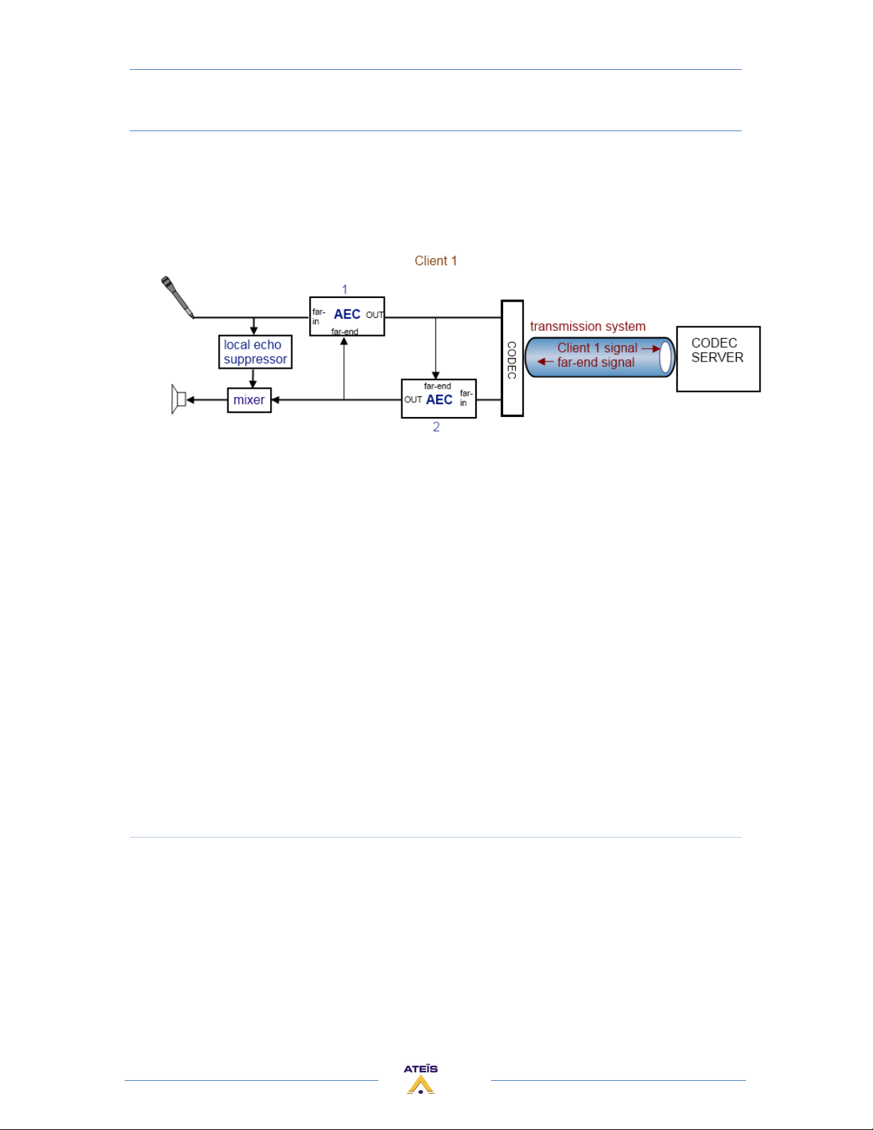
For example let's take this complete configuration:
This procedure is decrypted on several pages but the idea is simple:
• Turn off local amplification
• Bypass the AEC
• Adjust signal coming from the other side
• Adjust local sources
• Adjust the local echo suppressors of the local sources
• Active the AEC
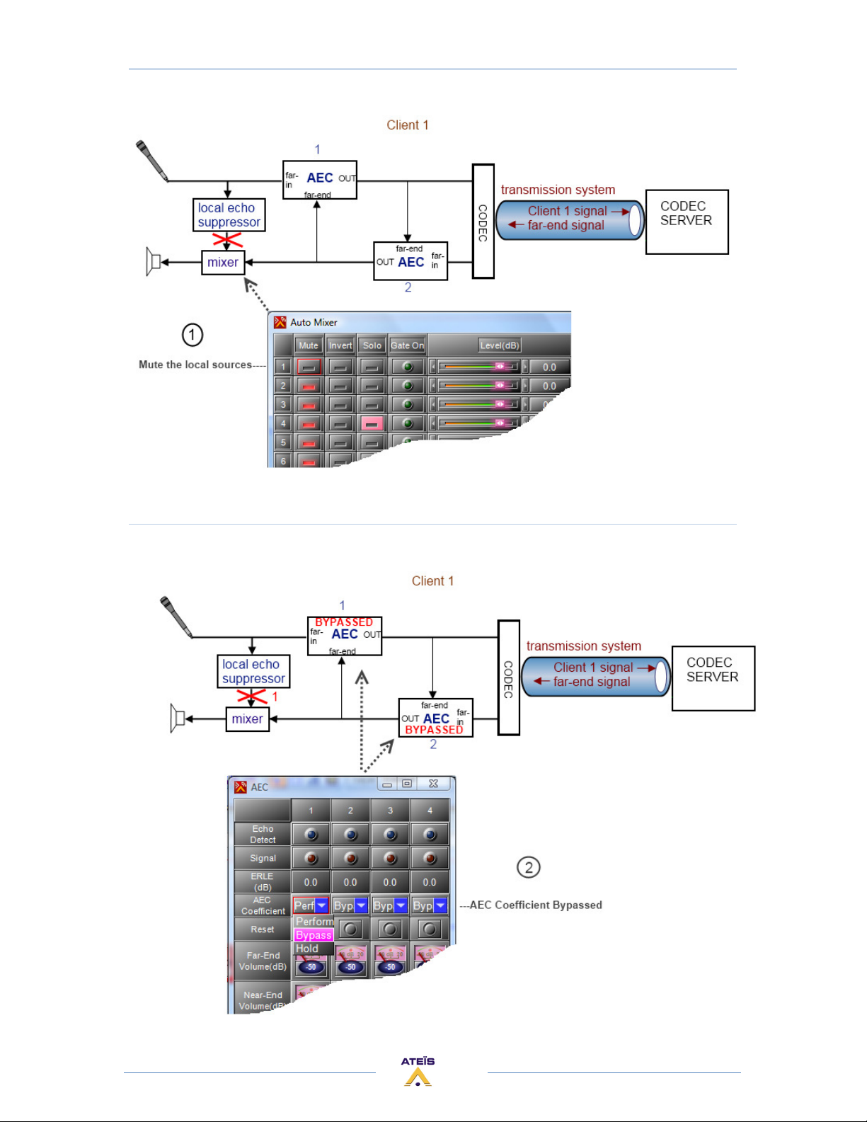
Turn off local amplification
1) If you have a local amplification of the local sources then turn off the local application. Only
the far end signal is allowed in the speakers.
Mute the local sources in the mixer of the local amplification and just enable the far-end
signal coming from the other side.
39
Page 40
ECS MANUAL
Version EN.1
Bypass the AEC
2) In the both AEC, set the AEC coefficient function to "Bypass".
40
Page 41
ECS MANUAL
Version EN.1
Adjust signal coming from the other side
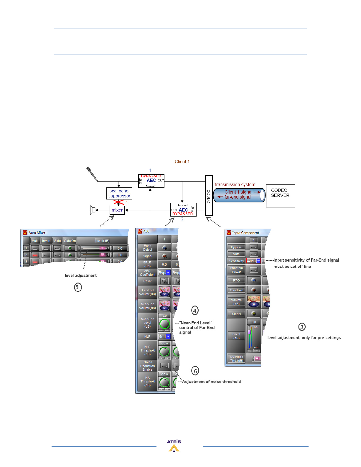
3) Make proper adjustment of the input sensitivity of the far-end signal coming from the other
side on the input component.
4) In the AEC 2, adjust the volume level of far-end signal coming from the other side with NearEnd parameter.
5) Make proper adjustment of the volume level of the Mixer until the audio from the other side
is clear and without feedback noise.
6) In the AEC 2, make proper adjustment of Background Noise Threshold, then To Press Noise
reduction Enable button to make noise reduction working.
41
Page 42
ECS MANUAL
Version EN.1
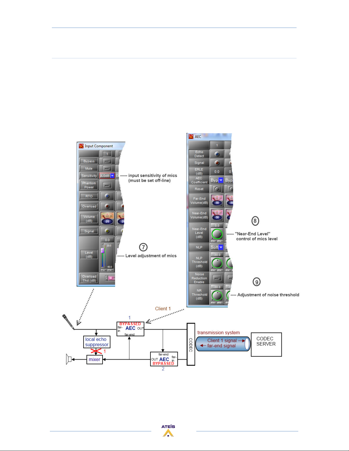
Adjust local sources
7) Make proper adjustment of the input sensitivity of the local microphones on the input
component.
8) In the AEC 1, adjust the microphone volume level with Near-End parameter.
9) In the AEC 1, make proper adjustment of Background Noise Threshold, then To Press Noise
reduction Enable button to make noise reduction working.
42
Page 43
ECS MANUAL
Version EN.1
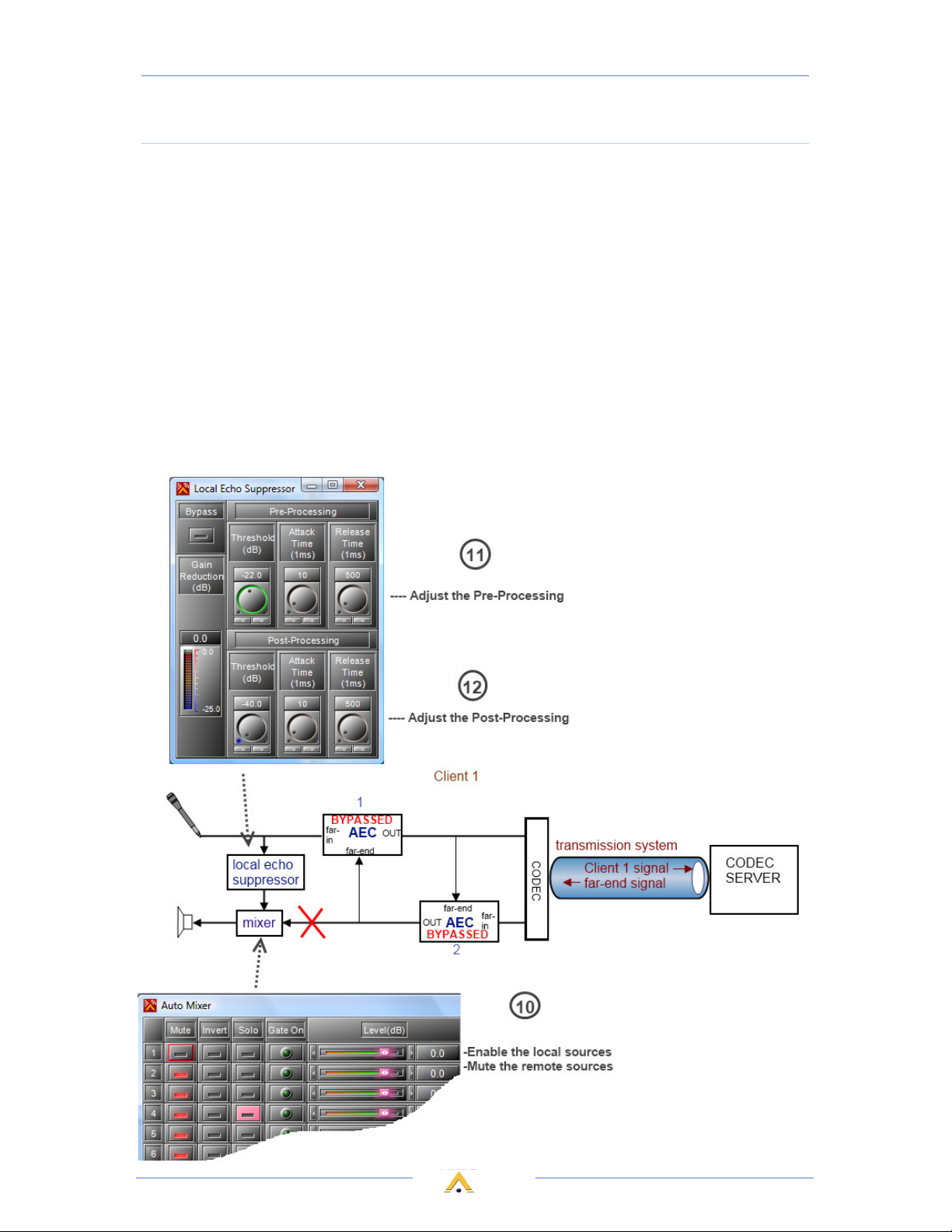
Adjust the local echo suppressors of the local sources
If you have a local amplification, the purpose of this step is to turn on the local amplifier application
and to turn off the signal coming from the other side. Only the far-in signals (microphones) are
allowed in the speakers.
10) Enable the local sources in the mixer of the local amplification mute the far-end signal
coming from the other side.
11) Make adjustment of Pre-Threshold of LES (Maximum audio level).
12) Make adjustment Post-Threshold of LES (Minimum audio level).
By default, the Pre-Threshold and Post-Threshold are set as -22dB and -40dB in table microphones. If
output volume of near end in LES is increased, it is essential to decrease Pre-Threshold level to
suppress the local audio echo feedback.
43
Page 44
ECS MANUAL
Version EN.1
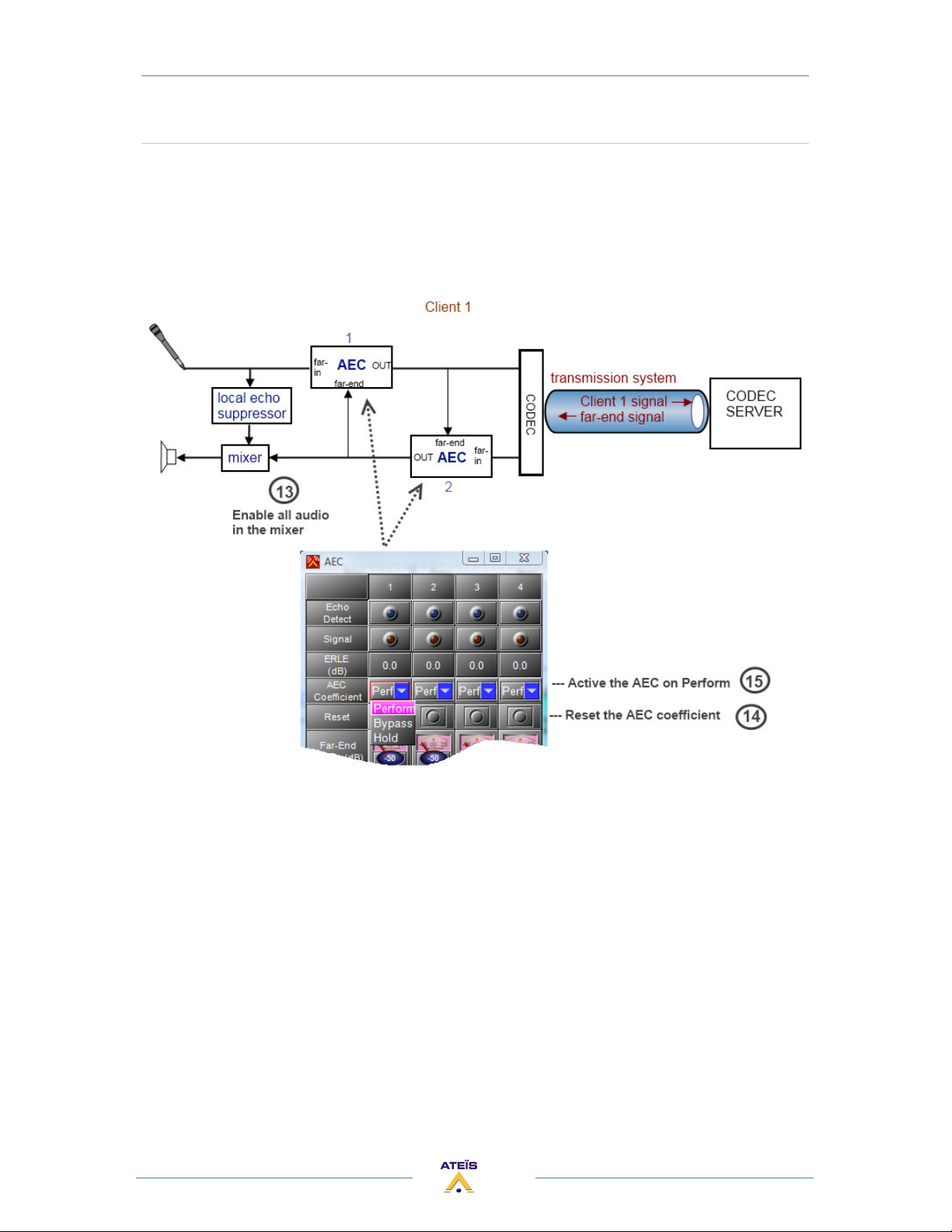
Active the AEC
13) Enable the local sources in the mixer of the local amplification.
14) In the both AEC, set the AEC coefficient function to "Reset".
15) In the both AEC, set the AEC coefficient function to "Perform".
The system is ready.
44
Page 45
TELEPHONE CARD
ECS MANUAL
Version EN.1
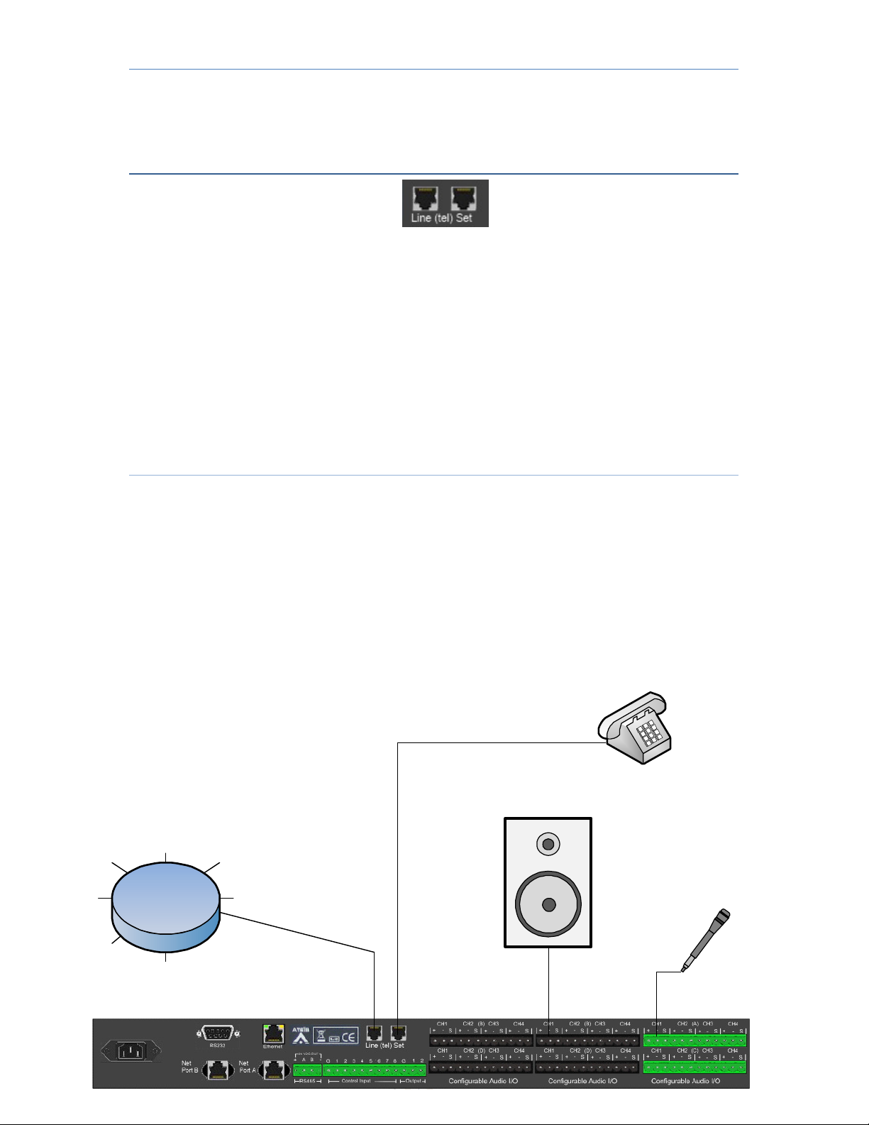
By linking the "Line" connector of the ECS to a telephone line, and by using a microphone and a
loudspeaker, then you can use the ECS as a telephone interface.
The interface of this telephone is available by using the dedicated components in Ateïs Studio
software, which are TC transmit and TC receive.
In option, you can also connect a telephone to the "Set" connector of the ECS allowing you to
have a physical interface.
The telephone line bandwidth is around 300hz – 3.3khz. It's due to its narrow bandwidth we
simulate.
The sound to be up to 6.6 kHz for comfortable listening. But there is a distortion resulting in a
metallic sound. You can put a low-pass filer to cut above 3.5kHz, that will help.
Schematic:
• Connect the direct telephone line or a line coming from a PABX central to the "Line" RJ11
connector of the ECS.
• In option, you can also connect a analogue telephone to the "Set" RJ11 connector of the
ECS.
• Connect a microphone or audio source to an input of the ECS. It will be used as
telephone microphone.
• Connect a listening system (loudspeaker) to an output of the ECS. It will be used as a
telephone speaker.
Analogue
telephone
Direct phone line
Or
PABX central
Amplified
Loudspeaker
Microphone
45
Page 46
ECS MANUAL
Version EN.1
Design in the ECS :
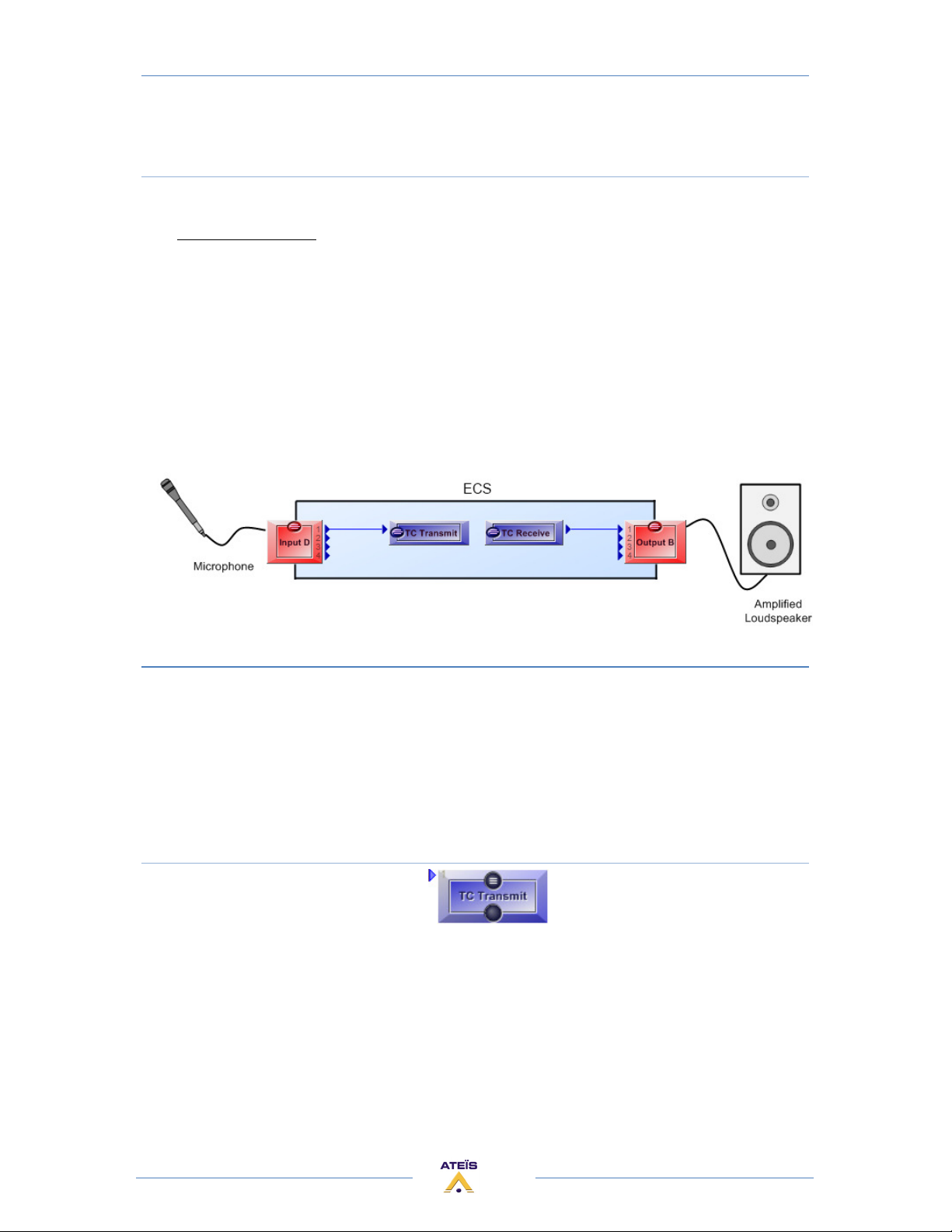
Regarding the basic schematic above, here is the corresponding design which must be created
with Ateïs Studio software.
The TC Transmit component is the interface between the local microphone (or audio sources)
and the telephone line. Its input has to be linked to an input component where the microphone is
physically connected to the ECS.
The TC Receive component is the interface between the local listening system (loudspeaker) and
the telephone line. Its output has to be linked to an output component where the listening system is
physically connected to the ECS.
You can use any input/output channels of the ECS.
TELEPHONE CARD COMPONENT
The telephone card component allows using the ECS as a telephone interface.
In the ECS configuration design, the telephone card consist of a TC transmit component and a TC
receive component. When your PC with Ateïs Studio software is connected live with the ECS, the TC
transmit and TC receive component offer a telephone interface allowing you to manage the
telephone call.
TC Transmit Component
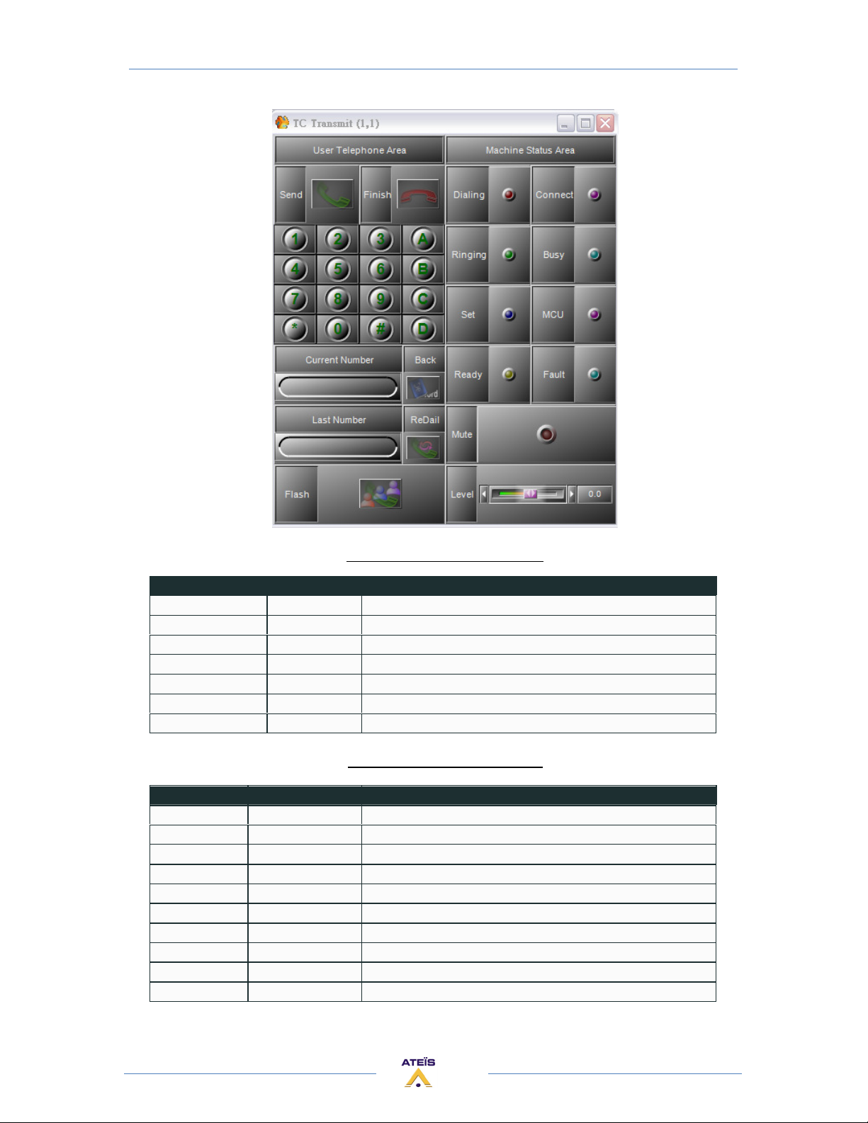
The TC transmit component provides the telephone keypad with the standard functions of a
telephone.
The component is split in two parts:
The "User Telephone Area", allowing you to type a telephone number, to start the call and to
stop it.
The "Machine status Area", which contains several status led showing you the current state of
the interface.
46
Page 47
ECS MANUAL
Version EN.1
User Telephone Area Parameters
Parameter Range Comment
Send Button Start the telephone call
Finish button Stop the telephone call
Current Number display Display the current target telephone number
Last Number display Display the previous target telephone number
Back Button Not available
ReDail Button Re-start the last telephone call
Flash Not available
Machine Status Area Parameters
Parameter Range Comment
Dialling led Light when the call is established, until the end of the call.
Connect led
Ringing led Light when the telephone is ringing on the other side
Busy led Light when the telephone line is busy on the other side
Set led Light when you pick up the telephone (if there is one)
MCU led Not available
Ready led Light when the telephone line is properly connected to the ECS
Fault led Light when the telephone line is not connected to the ECS
Mute button Mute the telephone line (mic)
Level -15 to 12(dB) Control the volume level of the microphone
47
Page 48
TC Receive Component
ECS MANUAL
Version EN.1
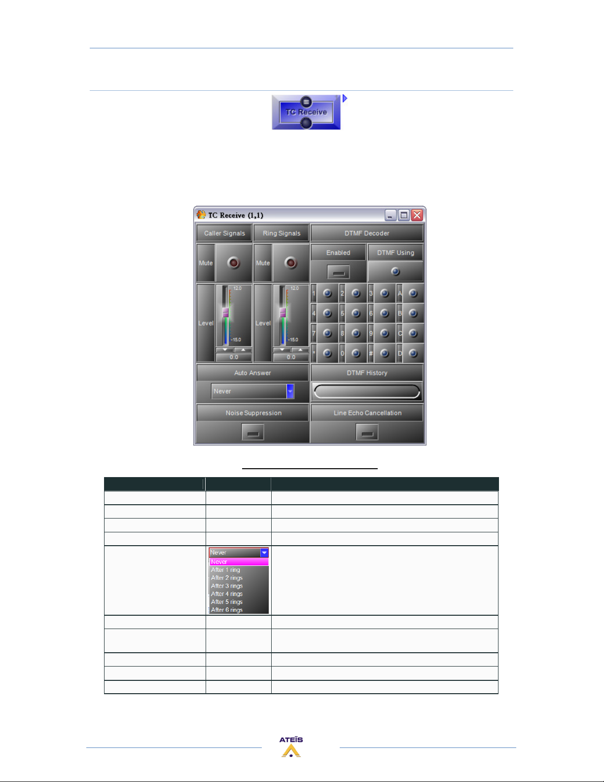
The TC receive component allows to see the incoming call with the DTMF Decoder and provides
also some controls. Here you can adjust the audio level of the incoming caller signal and of the
incoming ringing signal that you will hear in the speaker connect to the TC receive output.
The auto-answer function is available, allowing the ECS to automatically answer the incoming call.
A Noise suppression can be activated, and also a line echo cancellation in order to reduce the
noise and the echo due to the telephone line.
Machine Status Area Parameters
Parameter Range Comment
Caller signals / Mute Button/led Mute the caller signal
Caller signals / Level -15 to 12(dB) Level control of the caller signal
Ring signals / Mute Button/led Mute the ring signal
Ring signals / Level -15 to 12(dB) Level control of the ring signal
Auto-answer
Noise suppression Button Active the noise suppression on the caller signal
DTMF decoder /
enabled
DTMF using Light when a DTMF signal is detected
DTMF history Display the last DTMF signal received
Line echo cancellation Button Active the echo cancellation on the line
Button/led Enable the DTMF decoder
Active the auto-answer function, by selecting after how many
rings the ECS will answer.
48
Page 49
ECS MANUAL
Version EN.1
LOCAL ECHO SUPPRESSOR
The local echo suppressor is needed if a microphone is amplified and its signal is sent to a
loudspeaker for a local listening.
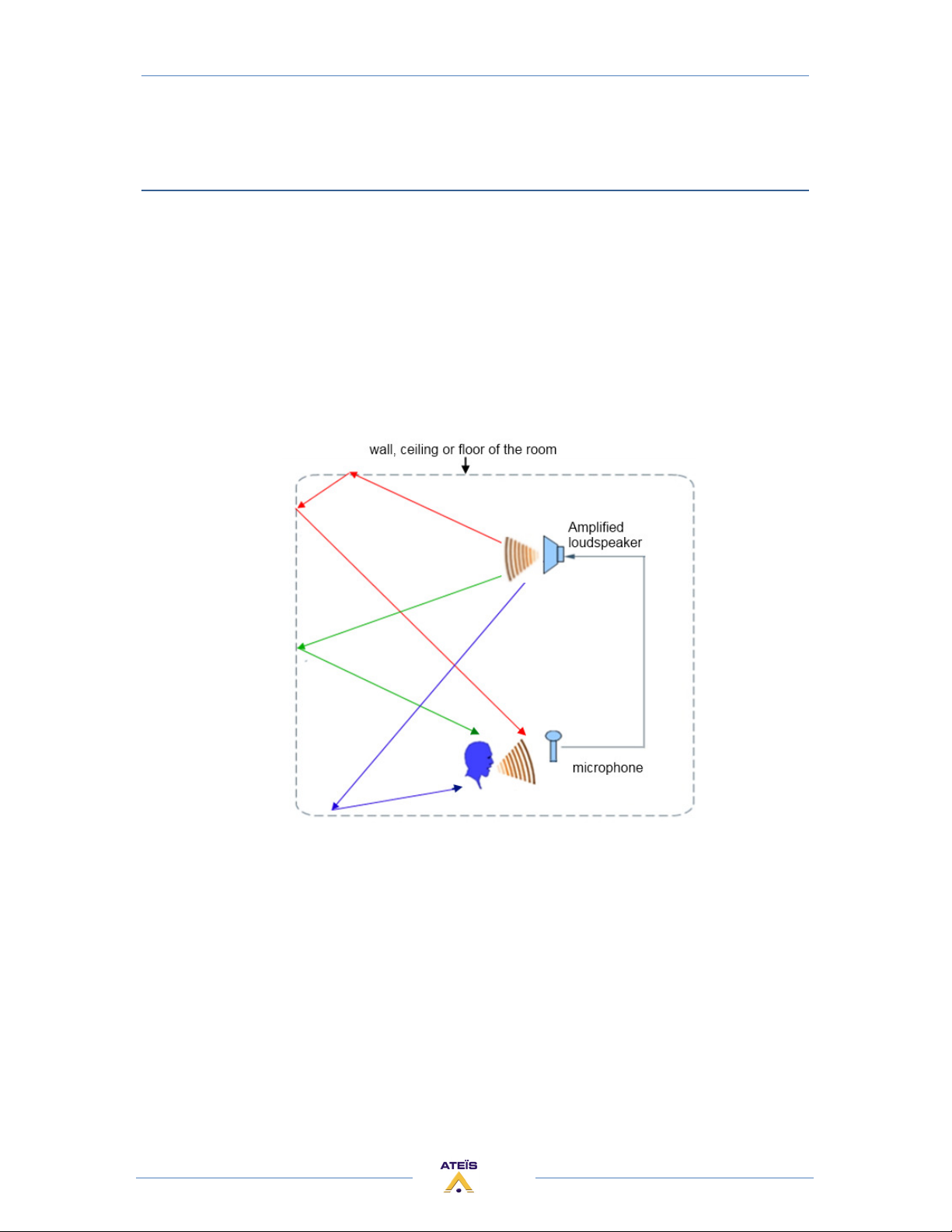
In this case two problems may appear. There is a risk of feedback Larsen, when the microphone
receives its own sound highly. The signal will be indefinitely amplified, which result in a high
frequency signal on the loudspeaker, very uncomfortable, called Larsen.
The second problem that may appear is the residuals echo. These echoes are due to the local
reflections.
As the sound in the room is sent to different directions, it reflects in the wall, the ceiling or the
floor. So the sound use different ways between the loudspeaker and the microphone, these ways
have different lengths that result by several little echoes.
49
Page 50
ECS MANUAL
Version EN.1
Schematic:
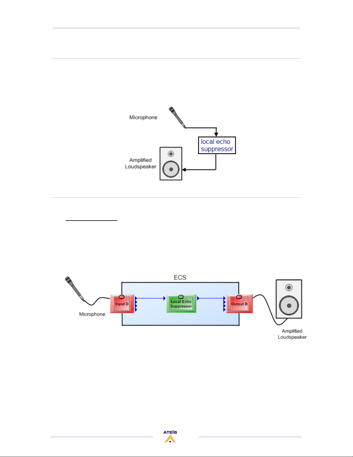
To avoid the problems explained above, a local echo suppressor is added between the
microphone and the listening system. The local echo suppressor component is split in two parts. The
Pre-Processing part take care of the residual echoes, and the Post-Processing part take care of the
feedback.
Design in the ECS:
Regarding the basic schematic above, here is the corresponding design which must be created
with Ateïs Studio software.
The input of the Local Echo Suppressor has to be linked to an input component where the
microphone is physically connected to the ECS.
The output of the Local Echo Suppressor has to be linked to an output component where the
listening system is physically connected to the ECS.
You can use any input/output channels of the ECS.
50
Page 51
ECS MANUAL
Version EN.1
LOCAL ECHO SUPPRESSOR COMPONENT
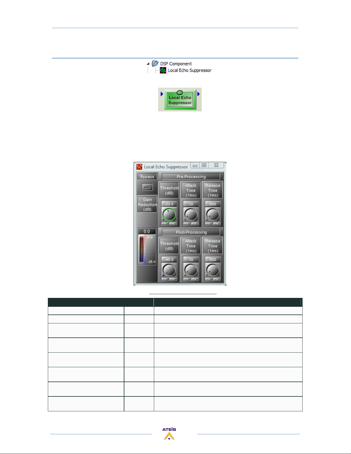
This component is designed for suppressing local Echo or feedback.
It's shared in two parts, pre-processing and post-processing.
The Pre-Processing limits the level to a threshold above which the gain will be reduced. This is to
avoid feedback.
The Post-Processing removes the echo below a threshold. This is to avoid the residual echo.
The control window of the "Local Suppressor Echo" module is opened by a double click on the icon
in the DESIGN AREA and appears like this:
Parameter Range Comment
Bypass Button Switches off the component operations
Gain Reduction Display the gain of output volume.
Pre-Processing > Threshold
(dB)
Pre-Processing > Attack Time
(ms)
Pre-Processing > Release Time
(ms)
Post-Processing > Threshold
(dB)
Post-Processing > Attack Time
(ms)
Post-Processing > Release Time (ms) 100 to 5k
-40 to 0
(dB)
1 to 100
(ms)
100 to 5k
(ms)
-40 to -20
(dB)
1 to 100
(ms)
(ms)
Local Echo Suppressor Parameters
When input volume is bigger than Pre-Processing Threshold ,it
will Reduce the volume to Threshold.
The time needed to change the volume from original level to the
expected level.
The time needed to change the volume from expected level to the
original level.
When input volume is smaller than Post-Processing Threshold ,it
will suppress the residue echo sound.
The time needed to change the volume from original level to the
expected level.
The time needed to change the volume from expected level to the
original level.
51
Page 52
ECS MANUAL
Version EN.1
ADDITIONAL DEVICES FOR ECS SYSTEM
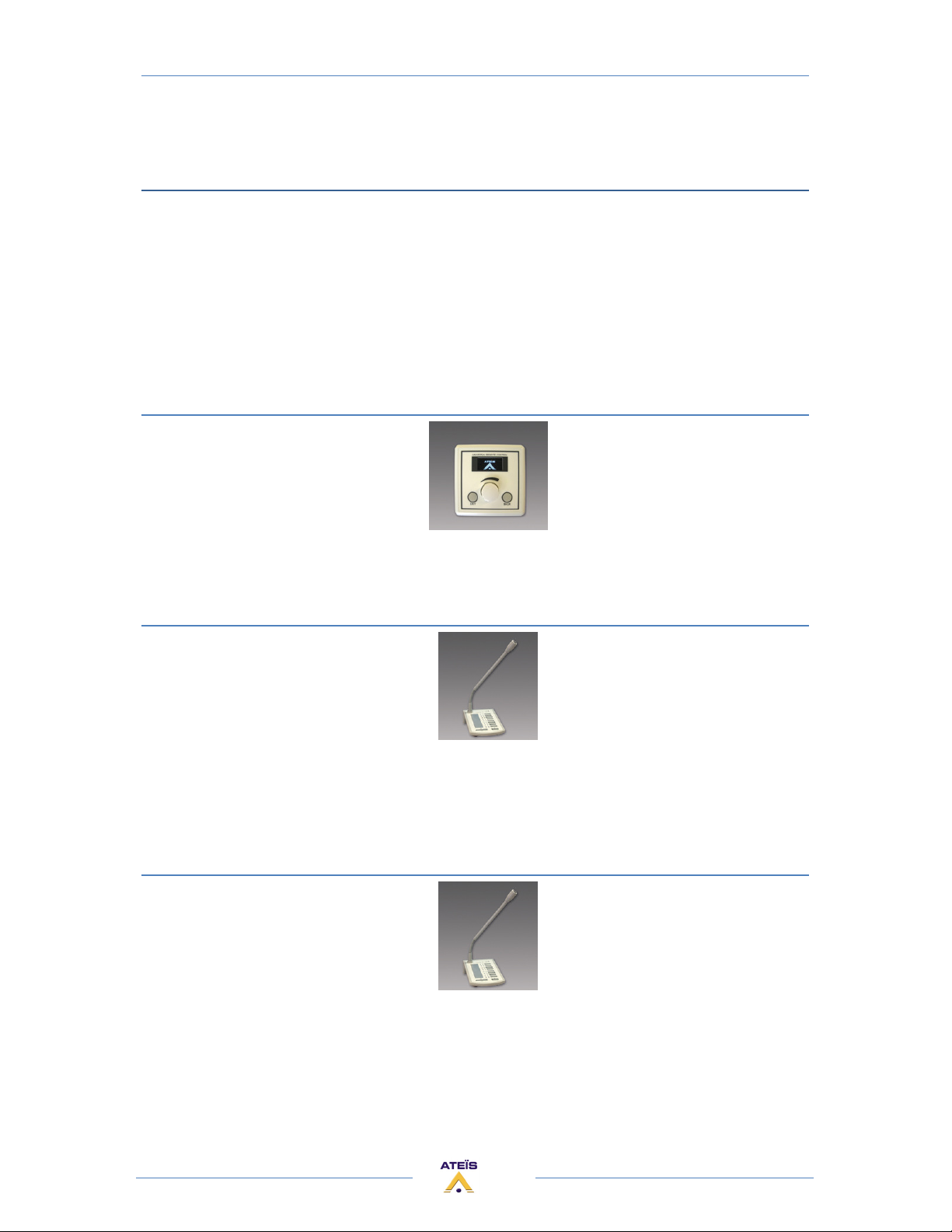
To maintain simple, secure and intuitive interfaces for operators, the ECS offers different types of
remote controllers:
• Universal Remote Control (URC)
• Programmable Paging Microphone (PPM, PPMTouch)
• RAC5 or RAC8
• To connect several devices on a ECS It may be helpful to use a Junction Box (JB)
Note: It is recommended to not put more than 8 remote devices (PPM and/or URC) on one ECS.
Putting more will increase the time response of the URCs and/or PPMs.
URC (UNIVERSAL REMOTE CONTROL)
URC can be fully programmed via ECS software to adjust every setting you want: volume, mute,
preset, components' adjustments... This remote device is connected to the ECS via the RS485 port.
PPM
Allow you to have up to 64 buttons (with additional Keypad). With the ECS Software you can
select in which area(s) (outputs) the microphone will be heard when you press a PPM's key. You can
also define pre or post chime when an announcement is done. This remote device is connected to
the ECS via the RS485 port.
The PPM has an Omni directional microphone capsule.
PPM-SP (stacking paging)
Same features as the PPM and a small memory (2min audio) in the PPM-SP allow storing the
message if the PPM-SP cannot rout the message to the desired zone. When the zone becomes
available the message will be played.
The PPM has a Cardio directional microphone capsule and an enhanced audio quality.
If the PPM-SP is linked to an additional keypad V2, the keypad is able to start messages.
52
Page 53
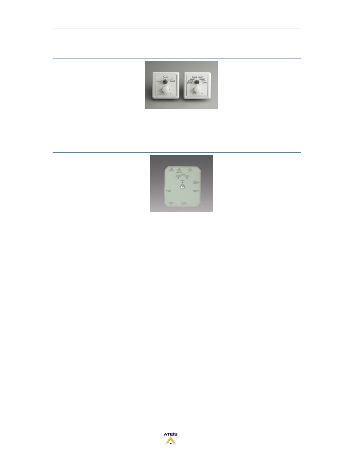
RAC (REMOTE ACCESS CONTROL)
ECS MANUAL
Version EN.1
Allow using analogue inputs for selecting a channel among 5 or 8 and setting the volume.
• RAC5 - Wall-mounted level and 5 sources selectors
• RAC8 - Wall-mounted level and 8 sources selectors
JB (JUNCTION BOX)
Easy chain connection of ECS peripherals (URC and PPM), using standard CAT5 cables.
KEY FEATURES:
• 5 x RJ45:
1) Connection to previous JB (or ECS bus on the first JB)
2) RS485-SIDE for URC connection
3) Easy connection to a Master PPM using the supplied 10 pins cable.
4) Connection to first Slave PPM (feature not available by now)
5) MAIN OUT connection to next JB
• 2 internal screw connectors for 0 dB audio:
• audio output from PPM microphone --> Audio Output (connect to the Audio
In of the ECS)
• audio input to PPM speaker --> Audio Input (connect to the Audio Output of
the ECS, if needed)
• 1 input for additional 24V power supply. (Depending on distance between ECS and
PPM/URC you will have to put an external power supply)
• 1 internal switch for PPM Master or Slave selection. (Slave features are not available for
the moment)
• 1 internal switch for System or Local power supply selection.
53
Page 54

ECS MANUAL
Version EN.1
Remote Devices Hardware Connections
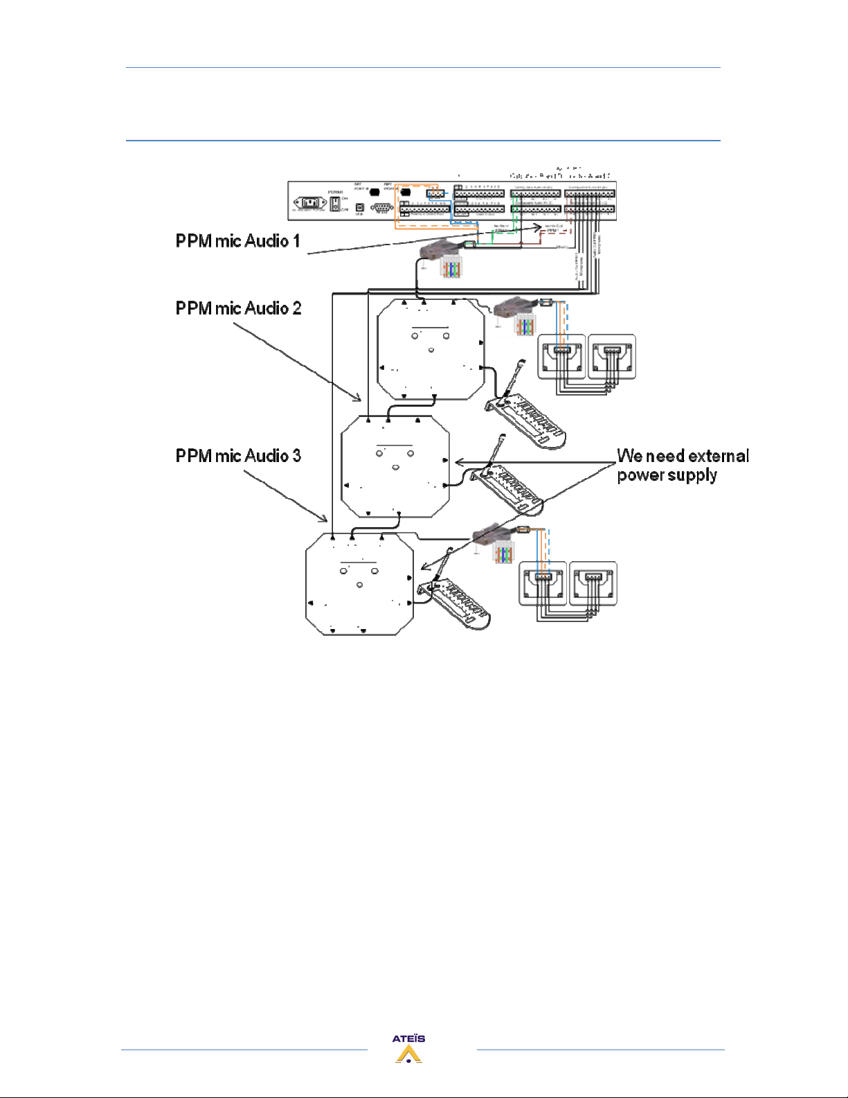
Because of the bus 485 and the audio, the connection of several PPM is not easy. You normally have
to create a bus with the RS485 (data and power) by using junction box (daisy-chain).
All audio from PPM must be sent to the LAP. Each Junction box has an audio output which is the
microphone signal of the PPM connected to the junction box.
Connect audio output from each junction box to an audio input of the ECS.
Each Junction box has also an audio input, used to get the audio from the ECS and sent it to the PPM
speaker.
Only for the first PPM/JB : The audio of the first PPM is already on the RJ45 linked to the ECS, so you
can either use the audio coming from the RJ45 or the audio coming from the JB audio output.
In summary:
• 485 : daisy chain, datas and power go from the ECS to the first JB (or PPM) then from
the first JB (PPM) to the second, etc.
• Audio: "star" connection, Each microphone and/or speaker is connected to an input and/or
output of the ECS
For other type of connection (Star connection, each PPM are directly connected to the ECS) we
cannot ensure a proper working.
Note: it is advised to not put more than 8 PPMs and or URCs on one ECS. It is working with up to
16 PPM but the response time is increased and you will have to use external power supply.
54
Page 55

ECS MANUAL
Version EN.1
Connection example for one PPM with JB
55
Page 56
ECS MANUAL
Version EN.1
Connection example for several PPMs with JB
56
Page 57
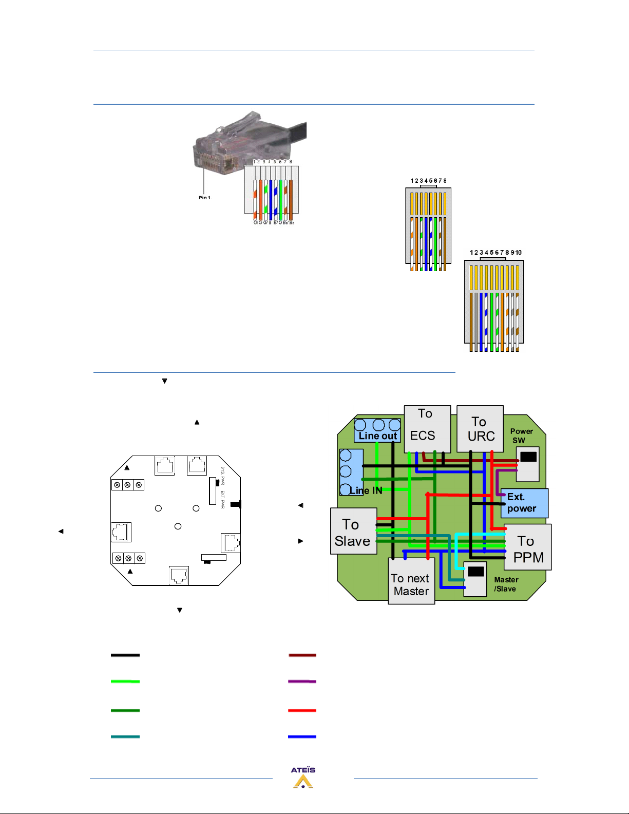
Rj45 pin out
ECS MANUAL
Version EN.1
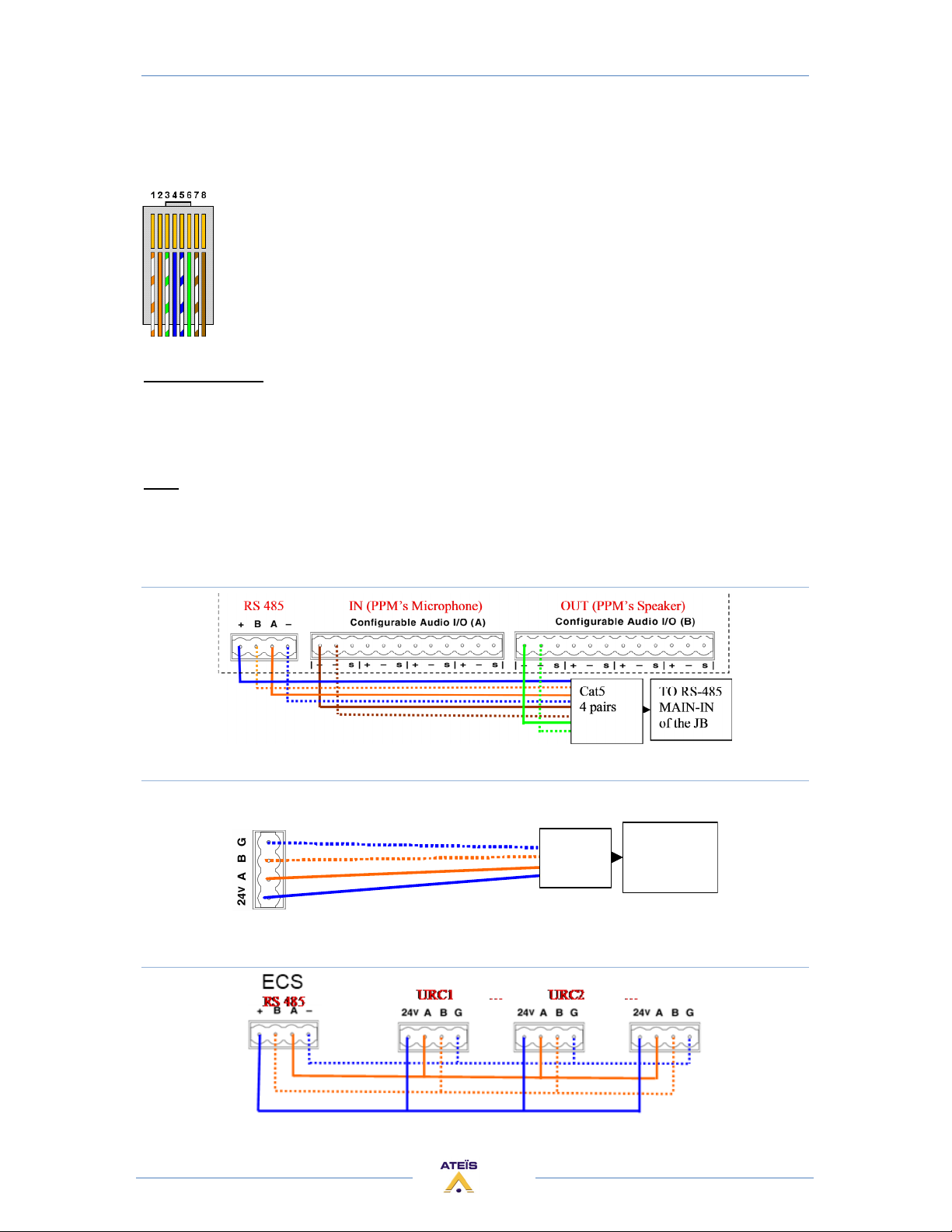
For practically all the wiring you'll need straight CAT5 cable (4 pairs):
With PPM, a straight CAT5 cable 5 pairs is needed (provided with PPM):
Junction Box
AUDIO
OUTPUT
S - +
SLAVE
PPM
S - +
AUDIO
INPUT
RS-485
MAIN-IN
+
AUDIO
OUT
RS-485
SIDE
LOCAL
POWER
(24 VDC)
RS-485
MAIN-OUT
Master S lave
MASTER
PPM
GND 24VDC <- from UAP
Line OUT (+ -) 24VDC <- from adapter
Line IN (+ -) 24VDC
Slave RS-485 (A B) Master RS-485 (A B)
57
Page 58
ECS MANUAL
Version EN.1
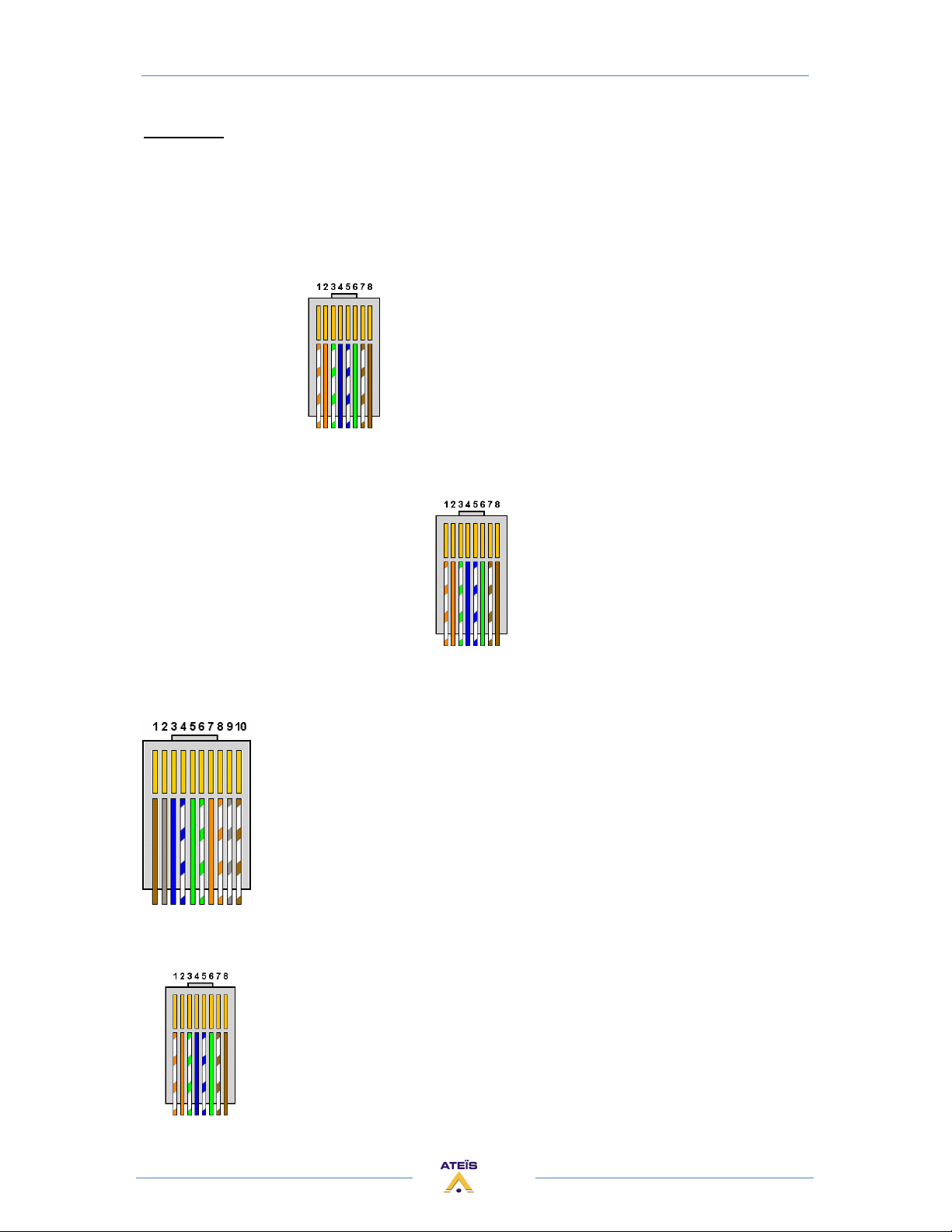
Connectors:
AUDIO OUTPUT (line out): This signal comes from the PPM's microphone to be connected in a ECS
input (Shielded audio cable)
RS-485 MAIN-IN + AUDIO OUT (To ECS): It is the BUS 485 to be connected into the ECS. You can also
have access with this JB output to the PPM's microphone signal
(to be connected to a ECS input)
Pin 1. RS-485 B
Pin 2. RS-485 A
Pin 3. Line in Pin 4. 24Vdc
Pin 5. Ground
Pin 6. Line in +
Pin 7. Line out Pin 8. Line out +
RS-485 SIDE: BUS 485 to connect URC
Pin 1. RS-485 B
Pin 2. RS-485 A
Pin 3. NC
Pin 4. 24Vdc
Pin 5. Ground
Pin 6 ~ 8. NC
LOCAL POWER (24VDC):To gives power to the JB through a local power supply
MASTER PPM (CAT5 5 pairs): To connect the PPM
Pin 1. Slave RS-485 A
Pin 2. 24Vdc
Pin 3. Master RS-485
Pin 4. Master RS-485 A
Pin 5. Line out + ( PPM Mic)
Pin 6. Line out - (PPM Mic)
Pin 7. Line in + (PPm speak.)
Pin 8. Line in – (PPm speak.)
Pin 9. Ground
Pin10. Slave RS-485 B
RS-485 MAIN-OUT (To next Master): To connect another JB (daisy-chain)
Pin 1. RS-485 B
Pin 2. RS-485 A
Pin 3. NC
Pin 4. 24Vdc
Pin 5. Ground
Pin 6 ~ 8. NC
58
Page 59
ECS MANUAL
Cat5
TO R
S-485
Version EN.1
AUDIO INPUT: To send audio signal from a ECS output to the PPM speaker (Shielded audio cable)
SLAVE PPM (CAT5 5 pairs): NOT AVAILABLE FOR THE MOMENT (to connect Slave PPM)
Pin 1. Slave RS-485 B
Pin 2. Slave RS-485 A
Pin 3. Line in Pin 4. 24Vdc
Pin 5. Ground
Pin 6. Line in +
Pin 7. Line out Pin 8. Line out +
Internal Switches:
POWER S/W: To choose between local power supply or the ECS power supply
Master/Slave:NOT AVAILABLE FOR THE MOMENT (chose if the PPM connected to this JB is a Master
or a Slave)
LEDs:
POWER SYSTEM: Lights if the power comes from a local power supply
POWER LOCAL: Lights if the power comes from ECS
READY: Lights if the Junction Box is ready to work
Connect JB to ECS
Connect URC to ECS with JB
URC
Connect URC to ECS
4 pairs
SIDE
of the JB
59
Page 60
ECS MANUAL
Version EN.1
Connect PPM to JB
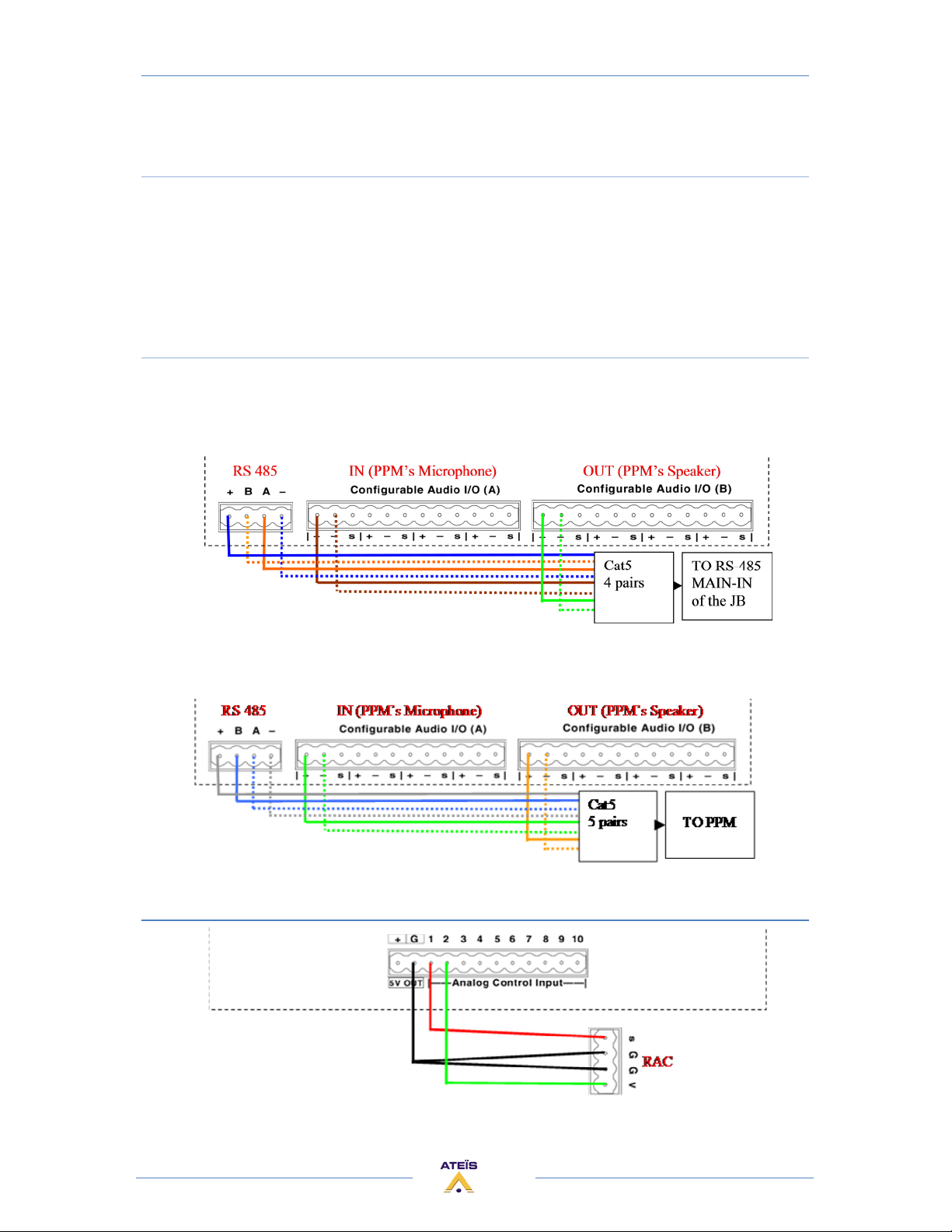
Simply use the CAT5 5 pairs provided with your PPM or a standard CAT5 4 pairs (Straight): from PPM
to MASTER PPM of the JB.
If you use a CAT5 4 pairs you probably will hear some data into the speaker of the PPM. This is due to
the internal wiring (if you do not use speaker, simply disconnect it).
Connect PPM to ECS
There is two way to connect one PPM
1) Use a 4 pairs between the ECS and the junction box, and then connect the PPM to MASTER
PPM of the junction box with a 5 pairs..
2) Use a CAT5 5 pairs directly between the PPM and the UAP, as follow.
Connect RAC
60
 Loading...