


 Loading...
DIVA system
User Manual
Version 1.0.0
© 2012 ATEÏS
www.ateis-europe.com
ATEÏS Europe BV - Sydneystraat 42 - 3047BP ROTTERDAM - NETHERLANDS
Phone +31 (0)10 2088690 - Fax +31 (0)10 2088699
P.O. box 12172, 3004 GD, ROTTERDAM - Chamber of commerce: 24465391 Rotterdam
Revision History
Time |
Version |
|
|
|
|
2012/09/03 |
1.0.0 |
The First Version. |

Contents |
3 |
|
|
Table of Contents
|
|
|
|
0 |
Introduction |
|
|
7 |
|
1.1 |
Welcome................................................................................................................................... |
7 |
||
1.2 |
Ateis ...................................................................................................................................Presentation |
7 |
||
1.3 |
EC Declaration...................................................................................................................................of Conformity |
9 |
||
Safety Declartion |
10 |
|||
Quick Start |
|
|
11 |
|
Product Features |
34 |
|||
4.1 |
DIVA...................................................................................................................................Series Audio Processor |
34 |
||
4.1.1 |
DIVA8M .......................................................................................................................................................... |
34 |
||
|
4.1.1.1 ......................................................................................................................................................... |
Overview |
34 |
|
|
4.1.1.2 ......................................................................................................................................................... |
What's inside the Box |
40 |
|
|
4.1.1.3 ......................................................................................................................................................... |
Installation |
40 |
|
|
4.1.1.4 ......................................................................................................................................................... |
Front Panel |
42 |
|
|
|
4.1.1.4 ......................................................................................................................................... |
Fireman Microphone |
43 |
|
4.1.1.5 ......................................................................................................................................................... |
Rear Panel |
44 |
|
|
|
4.1.1.5 ......................................................................................................................................... |
A) Control Inputs |
46 |
|
|
4.1.1.5 ......................................................................................................................................... |
B) Evacuation Inputs |
46 |
|
|
4.1.1.5 ......................................................................................................................................... |
C) RS232 Connector |
47 |
|
|
4.1.1.5 ......................................................................................................................................... |
F) Control Outputs |
48 |
|
|
4.1.1.5 ......................................................................................................................................... |
H) Amplifiers I/O |
49 |
|
|
4.1.1.5 ......................................................................................................................................... |
I) 100V Signal Links |
50 |
|
|
4.1.1.5 ......................................................................................................................................... |
J) Speaker Zone Outputs |
51 |
|
|
4.1.1.5 ......................................................................................................................................... |
K) PSS/PSM (RJ45) Connector |
51 |
|
|
4.1.1.5 ......................................................................................................................................... |
L) Ethernet (RJ45) Connector |
54 |
|
|
4.1.1.5 ......................................................................................................................................... |
N) Mic/Line Input (XLR) |
56 |
|
|
4.1.1.5 .........................................................................................................................................O) Music Inputs (RCA) |
57 |
|
|
|
4.1.1.5 ......................................................................................................................................... |
Q) Backup Pow er Input |
57 |
|
4.1.1.6 ......................................................................................................................................................... |
Peripherals |
58 |
|
|
4.1.1.7 ......................................................................................................................................................... |
Characteristics |
58 |
|
|
4.1.1.8 ......................................................................................................................................................... |
3rd Party Control |
60 |
|
|
4.1.1.9 ......................................................................................................................................................... |
LCD Menu |
61 |
|
|
|
4.1.1.9 ......................................................................................................................................... |
Evacuation List |
63 |
|
|
4.1.1.9 ......................................................................................................................................... |
EVAC Zone List |
64 |
|
|
4.1.1.9 ......................................................................................................................................... |
Fault List |
64 |
|
|
4.1.1.9 ......................................................................................................................................... |
Events List |
64 |
|
|
4.1.1.9 ......................................................................................................................................... |
Scheduler List |
64 |
|
|
4.1.1.9 ......................................................................................................................................... |
Setting Menu |
64 |
|
|
4.1.1.9 ......................................................................................................................................... |
Managing Music Sources |
71 |
|
|
4.1.1.9 ......................................................................................................................................... |
Messages and Microphone Calls |
71 |
4.1.2 |
DIVA8S .......................................................................................................................................................... |
75 |
||
|
4.1.2.1 ......................................................................................................................................................... |
Overview |
75 |
|
|
4.1.2.2 ......................................................................................................................................................... |
What's inside the Box |
78 |
|
© 2012 ATEÏS
3

4 DIVA system
|
4.1.2.3 |
Installation......................................................................................................................................................... |
78 |
||
|
4.1.2.4 |
Front Panel......................................................................................................................................................... |
79 |
||
|
4.1.2.5 |
Rear Panel......................................................................................................................................................... |
79 |
||
|
4.1.2.6 |
Characteristics......................................................................................................................................................... |
80 |
||
4.2 |
Consoles...................................................................................................................................and Accessories |
81 |
|||
4.2.1 |
Fireman Microphone.......................................................................................................................................................... |
81 |
|||
|
4.2.1.1 |
Characteristics......................................................................................................................................................... |
82 |
||
|
4.2.1.2 |
Configuration......................................................................................................................................................... |
82 |
||
4.2.2 |
PSM |
.......................................................................................................................................................... |
85 |
||
|
4.2.2.1 |
Overview......................................................................................................................................................... |
85 |
||
|
4.2.2.2 |
Control Panel......................................................................................................................................................... |
86 |
||
|
4.2.2.3 |
LED Indicators......................................................................................................................................................... |
87 |
||
|
4.2.2.4 |
Characteristics......................................................................................................................................................... |
88 |
||
|
4.2.2.5 |
Configuration......................................................................................................................................................... |
88 |
||
4.2.3 |
PSSG2 .......................................................................................................................................................... |
94 |
|||
|
4.2.3.1 |
Overview......................................................................................................................................................... |
94 |
||
|
4.2.3.2 |
Control Panel......................................................................................................................................................... |
95 |
||
|
4.2.3.3 |
Rear Panel......................................................................................................................................................... |
96 |
||
|
4.2.3.4 |
Configuration......................................................................................................................................................... |
96 |
||
|
4.2.3.5 |
Touch Screen......................................................................................................................................................... |
102 |
||
|
|
4.2.3.5 |
Configuration ......................................................................................................................................... |
103 |
|
|
|
4.2.3.5 |
General Options......................................................................................................................................... |
104 |
|
|
|
4.2.3.5 Audio Input and.........................................................................................................................................Output settings |
105 |
||
|
|
4.2.3.5 |
Screen Calibration......................................................................................................................................... |
108 |
|
|
|
4.2.3.5 |
Mechanical Buttons......................................................................................................................................... |
109 |
|
|
|
4.2.3.5 |
Working w ith the.........................................................................................................................................VACIE System |
109 |
|
4.2.4 |
PSSG2-E .......................................................................................................................................................... |
113 |
|||
|
4.2.4.1 |
Overview......................................................................................................................................................... |
113 |
||
|
4.2.4.2 |
Control.........................................................................................................................................................Panel |
114 |
||
|
4.2.4.3 |
Rear/Side.........................................................................................................................................................Panel |
115 |
||
|
4.2.4.4 |
Configuration......................................................................................................................................................... |
116 |
||
4.2.5 |
CD16 |
.......................................................................................................................................................... |
118 |
||
|
4.2.5.1 |
Overview......................................................................................................................................................... |
118 |
||
|
4.2.5.2 |
Front/Rear.........................................................................................................................................................Panel |
120 |
||
|
4.2.5.3 |
Characteristics......................................................................................................................................................... |
122 |
||
|
4.2.5.4 |
LED Indicators......................................................................................................................................................... |
122 |
||
|
4.2.5.5 |
Troubleshooting.........................................................................................................................................................Guide |
123 |
||
|
4.2.5.6 |
Configuration......................................................................................................................................................... |
124 |
||
4.3 |
Amplifier................................................................................................................................... |
|
124 |
||
4.3.1 |
SPA |
.......................................................................................................................................................... |
124 |
||
|
4.3.1.1 |
Overview......................................................................................................................................................... |
124 |
||
|
4.3.1.2 |
Front Panel......................................................................................................................................................... |
127 |
||
|
4.3.1.3 |
Rear panel......................................................................................................................................................... |
128 |
||
|
4.3.1.4 |
Characteristics......................................................................................................................................................... |
129 |
||
|
4.3.1.5 |
Parallel.........................................................................................................................................................Output |
130 |
||
System Functionality |
130 |
||||
5.1 |
DIVA...................................................................................................................................Software |
131 |
|||
5.1.1 |
Overview.......................................................................................................................................................... |
131 |
|||
5.1.2 |
System Requirement.......................................................................................................................................................... |
131 |
|||
5.1.3 |
Install DIVA..........................................................................................................................................................Software |
131 |
|||
5.1.4 |
Windows Layout.......................................................................................................................................................... |
135 |
|||
5.1.5 |
File |
.......................................................................................................................................................... |
137 |
||
© 2012 ATEÏS

|
|
|
Contents |
5 |
|
|
|
||
5.1.6 |
Edit .......................................................................................................................................................... |
138 |
||
5.1.7 |
View .......................................................................................................................................................... |
138 |
||
5.1.8 |
User .......................................................................................................................................................... |
139 |
||
5.1.9 |
Operation.......................................................................................................................................................... |
140 |
||
5.1.10 |
Tools .......................................................................................................................................................... |
141 |
||
5.1.11 |
Lock .......................................................................................................................................................... |
141 |
||
5.1.12 |
Window .......................................................................................................................................................... |
142 |
||
5.1.13 |
Help .......................................................................................................................................................... |
142 |
||
5.1.14 |
Toolbars .......................................................................................................................................................... |
142 |
||
5.1.15 |
Tab Bar .......................................................................................................................................................... |
144 |
||
5.1.16 |
Status Bar.......................................................................................................................................................... |
144 |
||
5.1.17 |
Design Component..........................................................................................................................................................Section |
144 |
||
5.1.18 |
Design View..........................................................................................................................................................Area |
146 |
||
5.1.19 |
Property Control.......................................................................................................................................................... |
146 |
||
5.1.20 |
Color Scheme.......................................................................................................................................................... |
147 |
||
5.2 |
How...................................................................................................................................To |
148 |
||
5.2.1 |
Save/Open.......................................................................................................................................................... |
148 |
||
5.2.2 |
Project .......................................................................................................................................................... |
149 |
||
5.2.3 |
Perform A..........................................................................................................................................................DIVA Master Network |
151 |
||
5.2.4 |
Add DIVA8S..........................................................................................................................................................slave |
152 |
||
5.2.5 |
Set Speaker..........................................................................................................................................................Parameters Setting |
154 |
||
5.2.6 |
Set Power..........................................................................................................................................................Monitor Setting |
155 |
||
5.2.7 |
Add Messages..........................................................................................................................................................Into DIVA |
156 |
||
5.2.8 |
Set up Front..........................................................................................................................................................Panel Message |
160 |
||
5.2.9 |
Create a Monitorable..........................................................................................................................................................Button |
163 |
||
5.2.10 |
Use Scheduler.......................................................................................................................................................... |
165 |
||
5.2.11 |
Use Logic..........................................................................................................................................................Inputs |
168 |
||
|
5.2.11.1 |
Normal.........................................................................................................................................................Logic Inputs |
170 |
|
|
5.2.11.2 |
Evacuation.........................................................................................................................................................Inputs |
171 |
|
|
5.2.11.3 |
External.........................................................................................................................................................Fault Inputs |
172 |
|
5.2.12 |
Do Phase..........................................................................................................................................................Evacuation |
172 |
||
5.2.13 |
Use Output..........................................................................................................................................................Relay |
177 |
||
5.2.14 |
Use Monitoring.......................................................................................................................................................... |
180 |
||
|
5.2.14.1 |
Explanation.........................................................................................................................................................About Monitoring Process |
184 |
|
5.2.15 |
Use Presets.......................................................................................................................................................... |
186 |
||
5.2.16 |
Manage Log..........................................................................................................................................................File |
188 |
||
5.3 |
Operation................................................................................................................................... |
190 |
||
5.4 |
User...................................................................................................................................Management |
192 |
||
5.4.1 |
Enter Password.......................................................................................................................................................... |
195 |
||
5.5 |
Device...................................................................................................................................Management |
196 |
||
5.5.1 |
Search and..........................................................................................................................................................Settings |
196 |
||
|
5.5.1.1 |
Set Computer.........................................................................................................................................................Network Parameters |
196 |
|
|
5.5.1.2 |
Configure.........................................................................................................................................................Network Options |
199 |
|
|
5.5.1.3 |
Search.........................................................................................................................................................Device |
200 |
|
|
5.5.1.4 |
IP Address......................................................................................................................................................... |
203 |
|
5.5.2 |
Verify Diva..........................................................................................................................................................Versions |
205 |
||
5.5.3 |
Update .......................................................................................................................................................... |
206 |
||
|
5.5.3.1 |
Update.........................................................................................................................................................Master Unit |
208 |
|
|
5.5.3.2 |
Update.........................................................................................................................................................Slave Unit |
209 |
|
|
5.5.3.3 |
Update.........................................................................................................................................................PSSG2 |
210 |
|
|
5.5.3.4 |
Update.........................................................................................................................................................PSM/CD16 |
211 |
|
|
5.5.3.5 |
Update.........................................................................................................................................................PSSG2E |
212 |
|
© 2012 ATEÏS
5

6 DIVA system
5.6 |
Event...................................................................................................................................Management |
212 |
||
5.6.1 |
Common Options.......................................................................................................................................................... |
214 |
||
5.6.2 |
Event Sequence.......................................................................................................................................................... |
215 |
||
5.6.3 |
Event Type.......................................................................................................................................................... |
217 |
||
5.7 |
Audio...................................................................................................................................Sources |
237 |
||
5.7.1 |
Music Source.......................................................................................................................................................... |
237 |
||
|
5.7.1.1 |
Use Music.........................................................................................................................................................Source From Front Panel |
240 |
|
|
5.7.1.2 |
With Modulation.........................................................................................................................................................Detection |
240 |
|
|
5.7.1.3 |
Use Music.........................................................................................................................................................Source From PSS |
241 |
|
|
5.7.1.4 |
Use Music.........................................................................................................................................................Source From Logic Input |
244 |
|
|
5.7.1.5 |
Software.........................................................................................................................................................Control |
246 |
|
5.7.2 |
MIC/LINE..........................................................................................................................................................Input |
247 |
||
|
5.7.2.1 |
With Modulation.........................................................................................................................................................Detection |
250 |
|
|
5.7.2.2 |
From Logic.........................................................................................................................................................Input |
251 |
|
|
5.7.2.3 |
From Software......................................................................................................................................................... |
253 |
|
5.8 |
DSP...................................................................................................................................Components |
254 |
||
5.8.1 |
Filter .......................................................................................................................................................... |
256 |
||
|
5.8.1.1 |
Hi/Lo Pass......................................................................................................................................................... |
256 |
|
|
5.8.1.2 |
PEQ ......................................................................................................................................................... |
260 |
|
5.8.2 |
Limiter .......................................................................................................................................................... |
264 |
||
5.9 |
3rd...................................................................................................................................Party Control |
268 |
||
5.9.1 |
Communication..........................................................................................................................................................Protocols |
268 |
||
|
5.9.1.1 |
Notifier......................................................................................................................................................... |
268 |
|
|
5.9.1.2 |
Modbus......................................................................................................................................................... |
271 |
|
|
5.9.1.3 |
Vox@net......................................................................................................................................................... |
272 |
|
5.9.2 |
Use RS232..........................................................................................................................................................Ports |
273 |
||
|
5.9.2.1 |
Notifier......................................................................................................................................................... |
273 |
|
|
5.9.2.2 |
Modbus......................................................................................................................................................... |
274 |
|
|
5.9.2.3 |
Vox@net......................................................................................................................................................... |
275 |
|
5.9.3 |
Put DIVA in..........................................................................................................................................................Vox@net |
275 |
||
Contact Infomation |
277 |
|||
|
Index |
|
0 |
|
© 2012 ATEÏS

Introduction 7
1 Introduction
1.1Welcome
Thank you for choosing ATEÏS DIVA. We here at ATEÏS hope you will enjoy our technology as much as we enjoyed developing and building it.
This files has been written for the ATEÏS DIVA software version: v3.0.1.50 and higher.
This manual is intended to provide the user with the necessary understanding of our system architecture as well as guide users through the configuration process.
This manual can be updated at any time without prior notice in order to keep it up to date.
If you find errors in this manual or would like to improve on the presentation, feel free to submit mistakes, suggestions or questions by sending an email.
We hope that this Help File Manual will provide you all the information you need. However if you have any questions, feel free to contact us.
1.2Ateis Presentation
ATEÏS has been in the professional audio market for close to thirty years and is viewed as a leading competitor in the Public Address, Voice Alarm, and Professional Audio Market in Europe, Asia, and the Middle East.
Products
The company offers a full range of audio equipment: microphones, preamplifiers, digital processors, digital audio matrixes, loud-speaker monitoring systems, amplifiers, etc. ATEÏS designs and manufactures leading products in the voice alarm systems market which have been certified EN60849 compliant by the TÜV and UL listed.
Development
Thanks to a development team of over forty engineers and a close connection to our customer base, we are able to respond rapidly to the demands of our various vertical markets with specific solutions and cutting edge technology. You can rest assured that our technology is always cutting edge with a view to the future.
ATEÏS Vertical Markets
Transportation (Railways, Subways, Airports)
High rise buildings
© 2012 ATEÏS

8 DIVA system
Hotels
Restaurants
Shopping malls
Theme parks
Places of worship
Stadia
Museums
Industrial
University and campus applications
© 2012 ATEÏS

Introduction 9
1.3EC Declaration of Conformity
© 2012 ATEÏS

10 DIVA system
2 Safety Declartion
 Do not expose the device to extreme temperatures, direct sunlight, humidity, or dust, which could cause fire or electrical shock hazard.
 Keep away water or other liquids from the device. Otherwise fire or electrical shock may result.
 Connect the power cord only to an AC outlet of the type stated in this Owner's Manual or as marked on the unit. Otherwise fire and electrical shock hazard results.
 When disconnecting the power cord from an AC outlet always grab the plug. Never pull the cord. A damaged power cord is a potential risk of fire and electrical shock hazard.
 Avoid touching power plugs with wet hands. Doing so is a potential electrical shock hazard.
 Take care for correct polarity when operating the device from a DC power source. Reversed polarity may cause damage to the unit or the batteries.
 Avoid placing heavy objects on power cords. A damaged power cord is a fire and electrical shock hazard.
 Do not cut, scratch, bend, twist, pull, or heat the power cord. A damaged power cord is a fire and electrical shock hazard. Ask your ATEÏS dealer for replacement.
 Turn off immediately the unit, remove the power cord from the AC outlet and consult your ATEÏS dealer in any of the following circumstances:
Smoke, odor, or noise getting out of the unit.
Foreign objects or liquids get inside the device.
The unit has been dropped or the shell is damaged.
The power cord is damaged.
If you continue using the device, fire and electrical shock may result.
 Do not drop or insert metallic objects or flammable materials into the unit as this may result in fire and electrical shock.
 Do not remove the device's cover, as there are exposed parts inside carrying high voltages that may cause an electrical shock. Contact your ATEÏS dealer if internal inspection, maintenance, or repair is necessary.
 Do not try to make any modifications to the device. This is a potential fire and electrical shock hazard.
 Avoid the device's ventilation slots to be blocked. Blocking the ventilation slots is a potential fire hazard.
© 2012 ATEÏS
Safety Declartion |
11 |
|
|
 To prevent the unit from falling down and causing personal injury and/or property damage, avoid installing or mounting the unit in unstable locations.
 Leave enough space above and below the unit to provide good ventilation of the device. If the airflow is not adequate, the device will heat up inside and may cause a fire.
 Operate the device in an environment with a free-air temperature of between 0 °C and 40 °C (32 °F and 104 °F).
 Turn off all audio equipment when making any connections to the device, and make sure to use adequate cables.
 Do not use benzene, thinner, or chemicals to clean the device. Use only a soft, dry cloth.
 If the device is moved from a cold place (e.g., overnight in a car) to a warmer environment, condensation may form inside the unit, which may affect performance. Allow the device to acclimatize for about one hour before use.
3 Quick Start
This topic is designed for "Quick Stat" and is only intent to give a rapid overview of how to start with DIVA. To obtain more precise details on "how to" and for further information about more complex configuration possibilities, please read all topics in this manual.
 Basic Setup
Connections and Power Up
Fireman Microphone
o Connect the fireman microphone to the connector on the DIVA's front panel.
Music Sources:
o Connect a tuner on the Cinch connector labeled 1 under "Music Input" on the rear of DIVA.
o Connect a CD player on the Cinch connector labeled 2 "Music Input"
Speaker Lines
o Connect one speaker line to the "Zone 1" connector. The speaker positive cable should be connected to "LINEA+" and the negative cable to "LINEA-"
o Connect a second speaker line to the "Zone 1" connector. The speaker positive cable should be connected to "LINEB+ and the negative cable to "LINEB-"
o If more zones have to be used, please redo the same connection for ZONE2, ZONE3,
etc...
© 2012 ATEÏS

12 DIVA system
Voice Amplifier
o Connect the "AIN+", "AIN-" and " from the "VOICE AMP" connect to "Channel 1" amplifier's input.
Note: respect polarity to avoid inversion phase problem.
o Connect the "Channel 1" amplifier"output to the "VOICE AMP" "AOUT and "AOUT-" connectors
Note: respect polarity to avoid inversion phase problem.
Music Amplifier
o Connect the "AIN+", "AIN-" and " from the "MUSIC AMP" connect to "Channel 1" amplifier's input.
Note: respect polarity to avoid inversion phase problem.
o Connect the "Channel 2" amplifier"output to the "MUSIC AMP" "AOUT and "AOUT-" connectors.
Power Supply
o To ensure the surveillance role, the power supply have to be secured.
Evacuation Button:
o Connect a button between EVAC1+ and EVAC1-.
 Slave add and set up
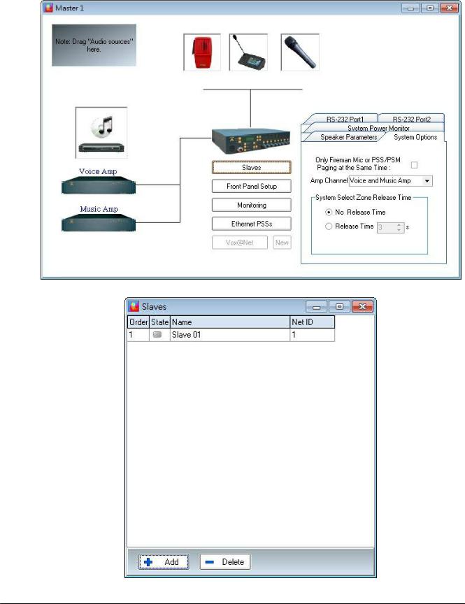
The Slave unit is for adding zones, one DIVA master unit can connect with 15 slave units. The maximum is 128 zones per system. The Fig3-1 shows the slave button in DIVA software, press it and you can see the pop-up window as Fig 3.2. Net ID in this table is the same with Slave's knobs on rear panel, the monitor detects the slave units through the ID numbers.
© 2012 ATEÏS
Quick Start |
13 |
|
|
Figure 3-1: Slave add button
Figure 3-2: Slave list w indow
© 2012 ATEÏS
14 DIVA system
 Software Start Up
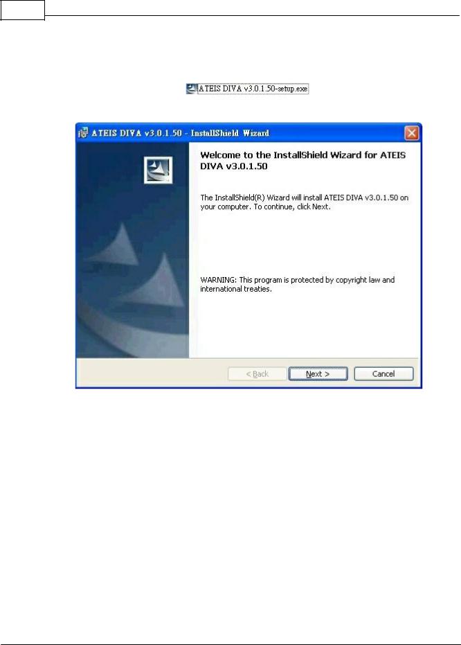
First of all, please install the DIVA which could be found on the Ateis-International website.
After double-clicking the DIVA Setup , please follow the next few step to complete the installation.
Figure 4: DIVA InstallShield Wizard start page
After the installation process complete, launch DIVA software from the Start menu or the desktop shortcut automatically installed.
 DIVA Configuration
The first steps to DIVA's configuration, is to set up network parameters and to test communication.
© 2012 ATEÏS
Quick Start |
15 |
|
|
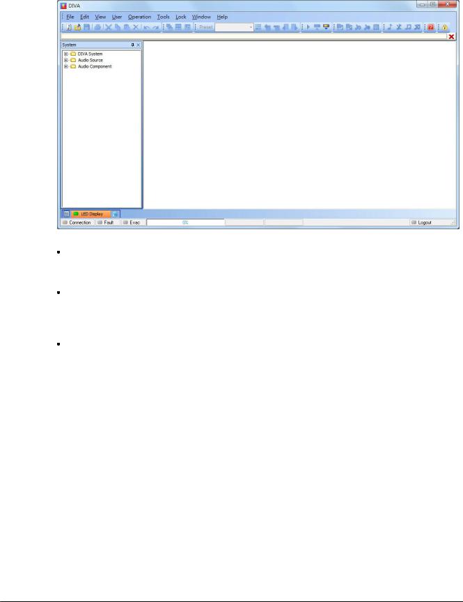
Figure 5: DIVA Softw are front page
The start page is represented on Figure 5. A first thing to do is to start a new project by clicking on or by going trough the menu file. This will launch a new window named "System" displayed on Figure 7.
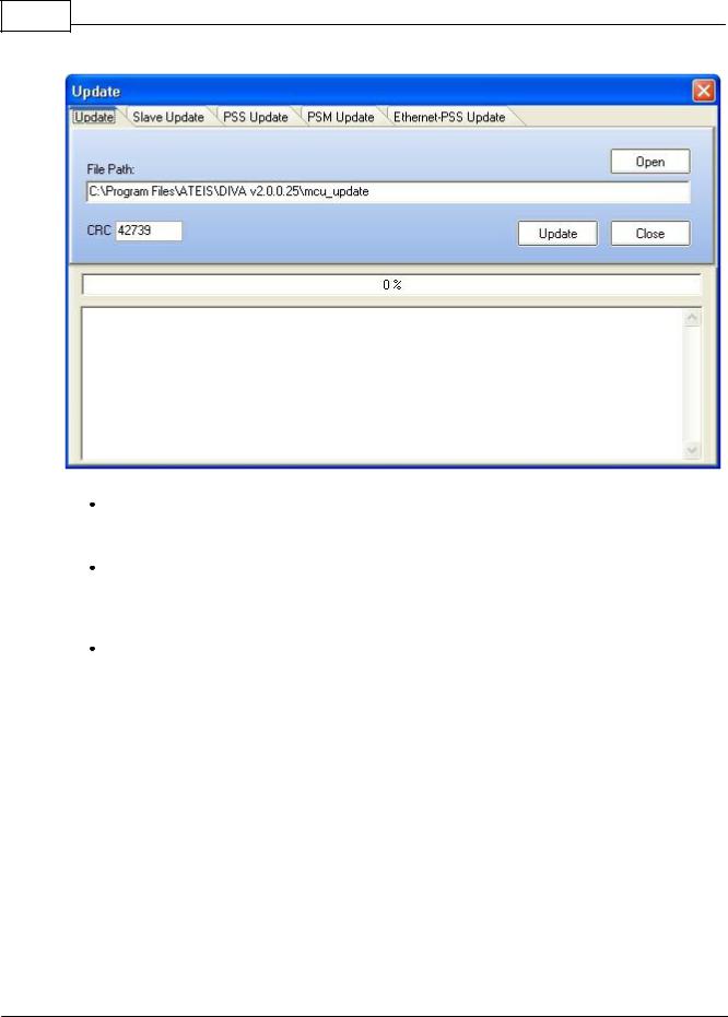
If this is the first installation, please update the DIVA software to the latest version available on our website. In the DIVA software click on the menu "tools-> update". In the update window (Figure 6), verify that the path specified is the one corresponding to the last version software, if not click open and choose the right one. Then click on the update button.
DIVA software will ask for password. For default users have been set into DIVA:
o User1: ATEIS1 Password: ATEIS1 User level: 1
o User2: ATEIS2 Password: ATEIS2 User level: 3
o User3: ATEIS3 Password: ATEIS3 User level: 3
o User4: ATEIS4 Password: ATEIS4 User level: 4
© 2012 ATEÏS
16 DIVA system
Figure 6: Update w indow
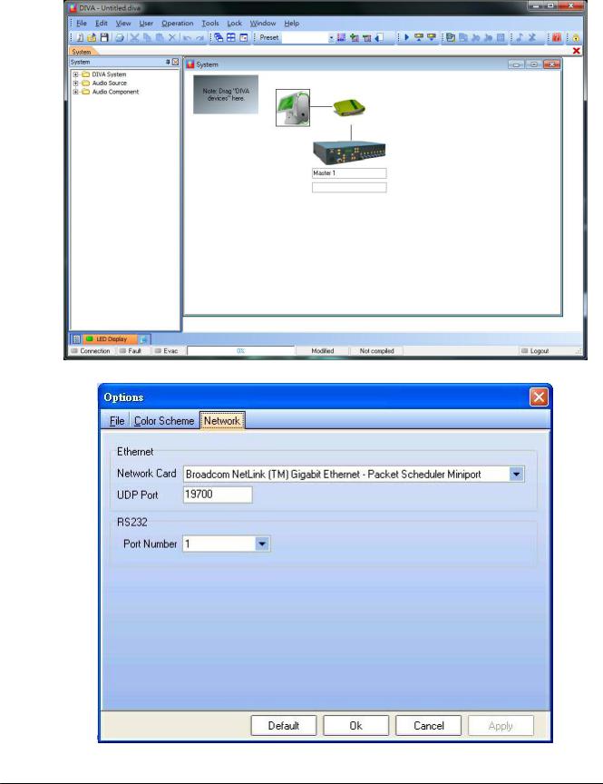
Next step is to set the network option. Simply click F12 or menu "Tools->Options". new pop window will appear directly on the network options page (Figure 8). Please check that the network card is one to be used.
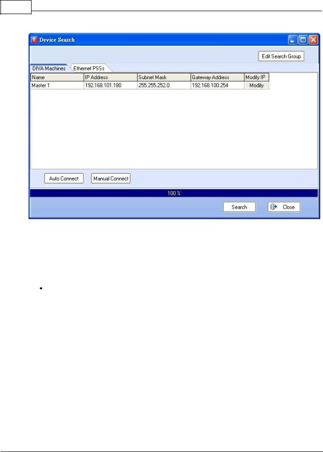
The devices connected to the TCP/IP network have to be detected. Click on the menu "Tools- >Device Search". In the new window, click on device "Start Search" button to check if the Network is correctly set up. A list of all networked devices is displayed. If your Master DIVA is not detected, please check cables and verify the IP address assignment.
Select the Master DIVA you want to work on and then click "Auto Connect". After connection, you will be able to see the IP address of the master on the system window.
© 2012 ATEÏS
Quick Start |
17 |
|
|
Figure 7: New System
Figure 8: Netw ork options page
© 2012 ATEÏS
18 DIVA system
Figure 9: Device Search page
 Event Philosophy
For a better understanding of how the DIVA works, a quick "Events" explanation is needed.
Event can be compare to an action. Each action or event can be started by a multiple of different ways: external trigger, modulation detection, etc. Those events are hierarchically organized by priority levels set for each one of them. You also can set permanent event like playing music.
Music
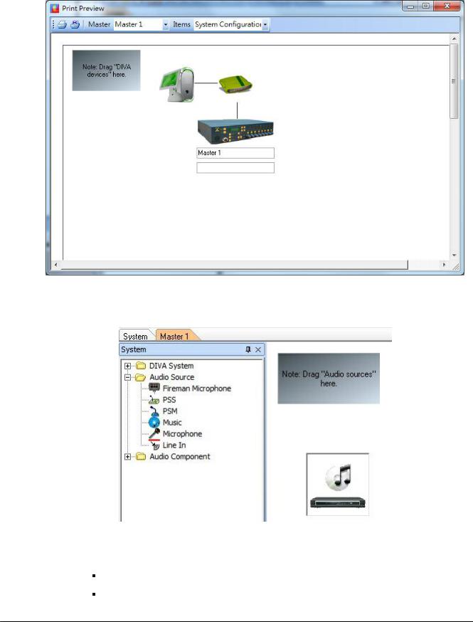
Now the DIVA connections are configured. The following step is how to set the system for using audio external sources, like tuner, cd player, computer, etc., and assigned them to zone. In the main system page (Figure 7), double click the DIVA Icon after having rename DIVA apparel according to your wishes, here DIVA1 (default is "master1"). A "DIVA1" pop window is displayed (Figure 10).
© 2012 ATEÏS
Quick Start |
19 |
|
|
Figure 10: Master page
In the tree folder, click on audio. It will display all the audio sources available for DIVA. Simply drag and drop the music icon on the corresponding drawing in the DIVA1 window (Figure 11). The connection picturing will automatically show that the connection exists.
Figure 11: Adding music source
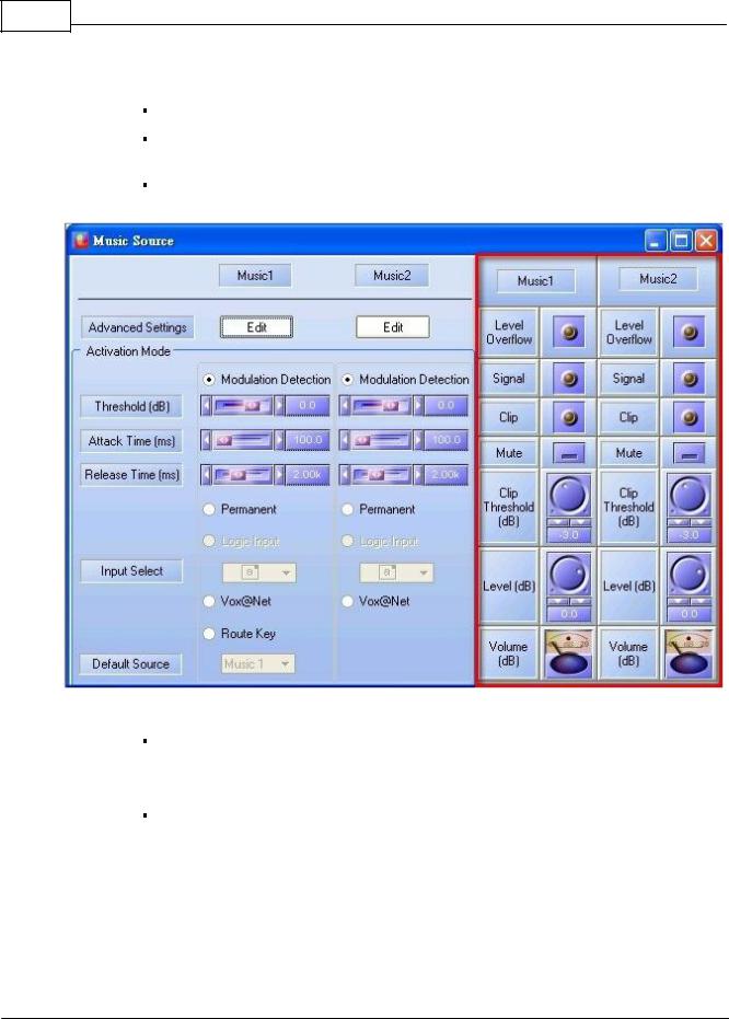
oDouble Click on the music source icon to open the "Music Source" window(Figure 12). On the figure, the part that is red framed is for the real time control.
In order to achieve your aim, you need to specify some parameters:
Select the Route Key mode under Music 1. The music sources will be controllable from
© 2012 ATEÏS
20 DIVA system
the front panel.
Click on Edit, for Music1 and Music2, in order to set event's parameters
Define the priority from 0 to 20, default is 20. Note: 0 is the highest priority. Here music has been set to 13.
The event "Play Music" is created automatically as soon as you configure you music source.
Figure 12: Music Source w indow
In the "Advance Setting" page, tick the "Pre-define Zone Enable". Then are able to define the zone where music will be played, here zone 1, 2, 3.
Note: you cannot define different zone for the two music sources.
Click the OK button.
© 2012 ATEÏS
Quick Start |
21 |
|
|
Figure 13: Play Music Event w indow
Configure your default source. Choice is between music source 1 and 2 (here 1).
Your system is now configured to play music from the music source 1 and 2. Please save your project before going to next step and close the "Music Source" window.
Note: At this time, you won't be able to hear music before compiling your file and store it into DIVA.
 Messages
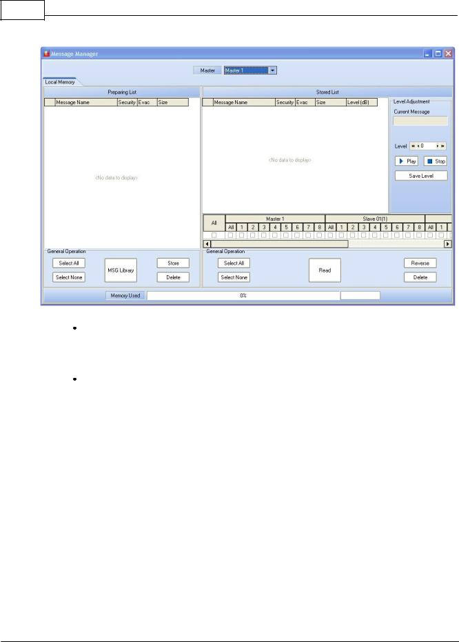
This section will explain how to set up messages (like alarm, evacuation, test, etc.) and how to use them.
The messages are administered with the so-called "Messages Manager". To add messages to message library, just save your messages in .wav format (16bit, 16kHz) into the "message lib" folder under the "Programe Files ->Ateis ->ATEIS DIVA folder.
To access the messages manager, please follow the next steps.
Click on the menu "view" -> "Message". The message page will display(Figure 14).
© 2012 ATEÏS
22 DIVA system
Figure 14: Message Window
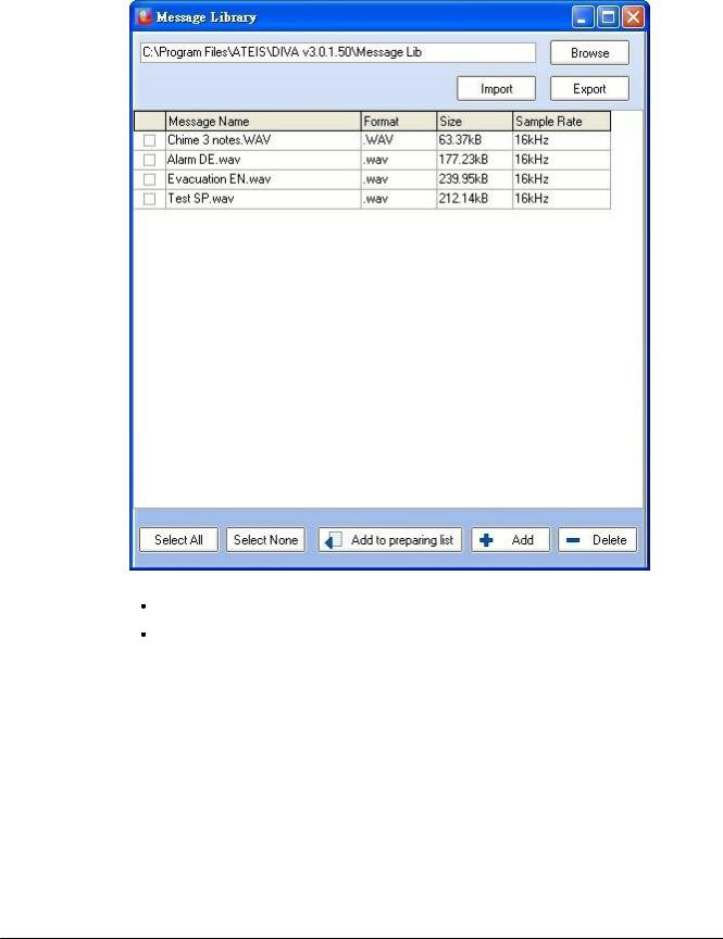
Click on the "MSG Manager" button. A new "Message Library" window appears. In the Library (Figure 15), all the messages in the library files are display. Simply tick the one you want, here all, to import into DIVA and click the "Add to DIVA" button. You will automatically return to Message page.
Once you are back in the message window, you can select the messages to store in DIVA and specify if there are security messages or not. Simply tick the right cases, and then push the "Store" button. For this example, all of them are selected and security has been desired for "Alarm DE" and "Evacuation EN".
© 2012 ATEÏS
Quick Start |
23 |
|
|
Figure 15: Message Manager Library page
Close the message page and go back on the "DIVA1" page
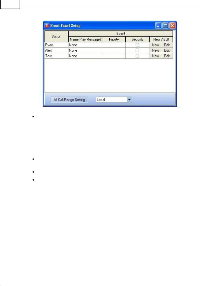
Click, under DIVA icon, the "Front Panel Setup"(Figure 16). You need to assign an event to the message buttons of the front panel (Evac, Alert and Test). For each button, make a new event and then edit the events (example on Figure 17).
© 2012 ATEÏS
24 DIVA system
Figure 16:"Front Panel Setup" w indow
In dedicated area of "Play Message Event window (Figure 17), change the name, choose a priority and tick if it's a security message or not. Under "Message" emplacement, choose with the drop-down menu the right message for the event. You can also define the "Play Mode" option: peat for ever or repeat for a definable number of time. Please choose between the "cancel all" or "Coexist" option. "Cancel All" consist of cancellation all the messages or events, with a lower priority, that are currently playing in the selected zone. "Coexist" permit to momentarily disable the current message or event and to retrieve it as soon as the one with a higher priority has finished.
Last thing to do is to define the zone where this message will be played. Here for the evacuation message, every zone are selected.
Repeat this section for the two more buttons (Alert and Test).
Close the "Front Panel Setup" window
© 2012 ATEÏS

Quick Start |
25 |
|
|
Figure 17: "Message Event" edit page
 Fireman Microphone
The Fireman microphone is a special monitored microphone. It means that at any time, the connection and the status of the microphone are measured and analyze. If any faults are detected, the front panel "Faults" led will illuminate.
In order to set up the use of the fireman microphone, please do as follow.
In the DIVA1 window, drag and drop the fireman microphone icon from the tree folder.
© 2012 ATEÏS
26 DIVA system
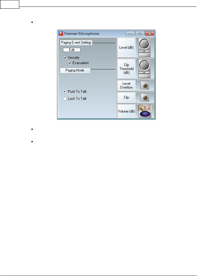
Double click the Fireman Microphone Icon. The "Fireman Microphone" window will open (Figure 18).
Figure 18: Fireman Microphone w indow
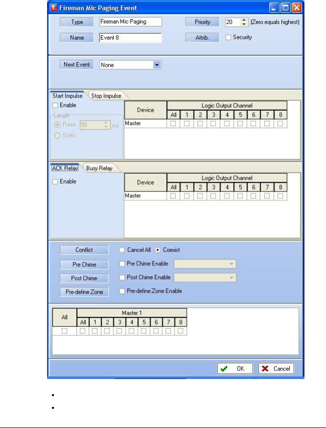
As for music, the event corresponding to the fireman microphone is automatically created. Click "Edit". A new pop-up window opens(Figure 19).
You need now to set the priority of the fireman microphone, by default it is set to 0, and tick security (as his main purpose is to deliver security warning).
© 2012 ATEÏS
Quick Start |
27 |
|
|
Figure 19: Paging Event w indow
Then, under "Conflict", choose "Cancel All" "Coexist according to your needs.
Tick "Pre-define Zone Enable" in order to define where the fireman microphone will play.
© 2012 ATEÏS
28 DIVA system
Choose zone according to your needs. Then click "OK".
In the Fireman Microphone window, select the behavior of the microphone under "Paging Mode". You can choose between "Push To Talk" or "Lock To Talk", respectively means that you can talk only while pushing the microphone button or talk after pushing once the microphone button (stop talking by pushing a second time the microphone button).
Close the "Fireman Microphone" window.
 GPIOs
GPIOs
The two next paragraphs EXFLT and INPUT discuss about, respectively, how to use GPIOs to have the SONaes default contact working and to add a external contactor to trigger an evacuation action.
To access the GPIOs page, click under menu "View -> GPIO"
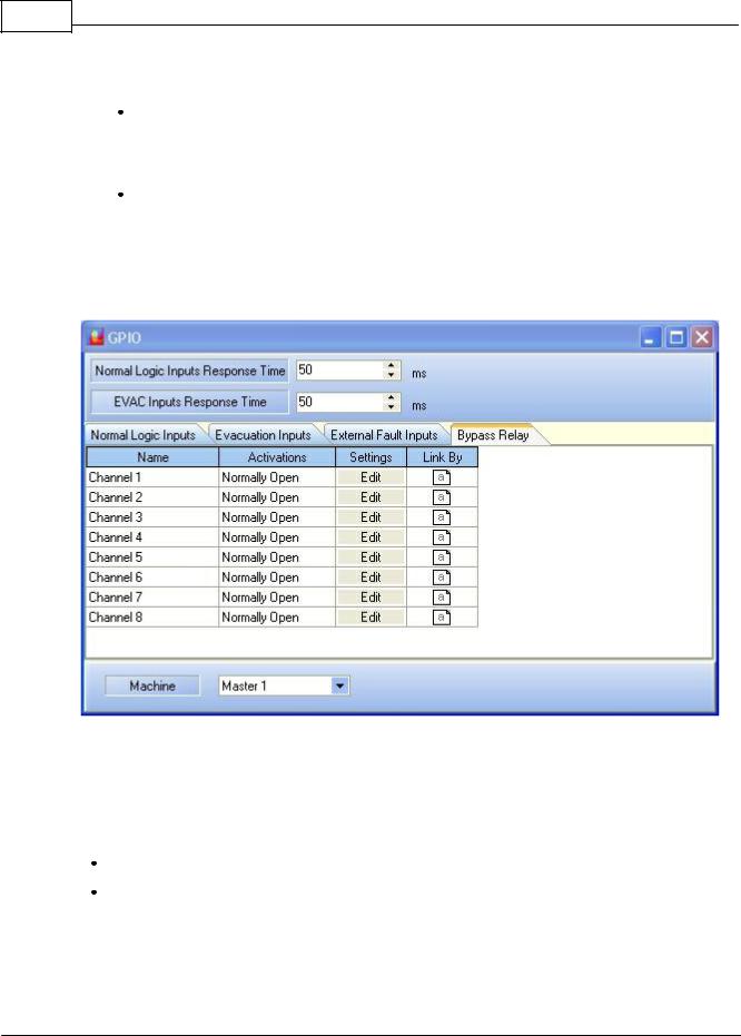
Figure 20: GPIO w indow
 EXFLT
EXFLT
Before going any further, the principle of security in the event have to be discussed. In case of power shutdown, the all DIVA system is designed to run under 24V battery. The DIVA is made for energy saving and will only keep security event alive. All the non-security event will be disable. The activation of an external fault input will force DIVA into security mode.
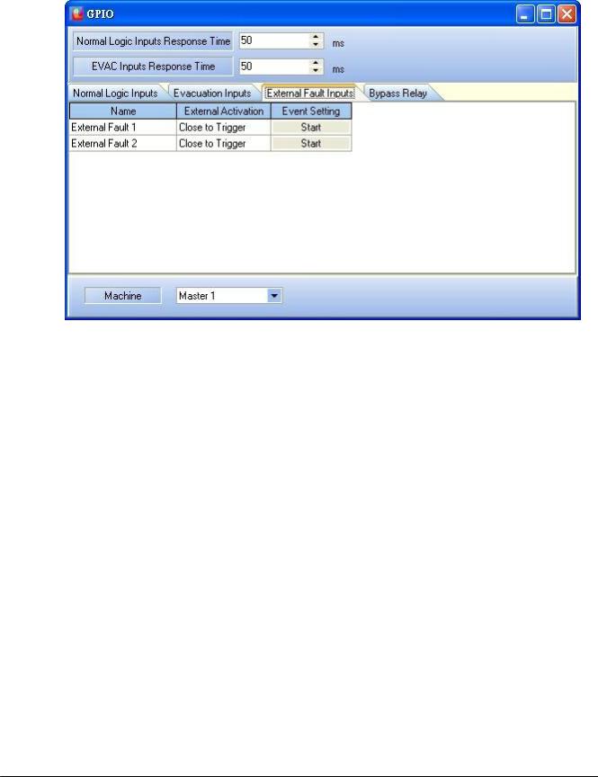
In the GPIO window (Figure 20), click the External Faults Inputs tab (Figure 21).
Tick the security square.
Note: You don't have to define an event in order to activate the external fault inputs. Ticking Security will induce DIVA to know in case this contact is activated that there is a major issue and will automatically go in power safe mode. So that only security event could be activated.
© 2012 ATEÏS
Quick Start |
29 |
|
|
Figure 21: External Fault Inputs page
 EVAC:
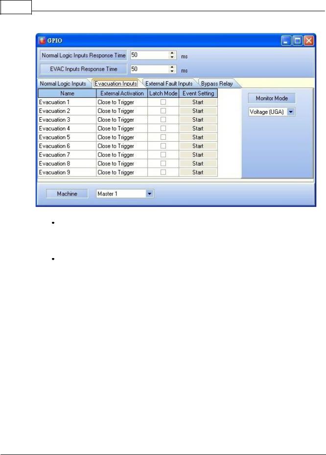
EVAC:
Evacuation inputs can be monitored input. It means that the line is under surveillance. In this example, we will activate the evacuation message by calling the "Evac" event.
Note: see annexe to know how to perform a monitored evacuation button/line.
In the GPIO window, please click on the "Evacuation Inputs" tab, see Figure 22.
© 2012 ATEÏS
30 DIVA system
Figure 22:GPIO's Evacuation Inputs tab
Under Channel 1, tick the "Latch Mode" square selector. "Latch mode" defines way the contact or button will work. In "Lach Mode", you will have to close/open the contact once for launching the event, and reclose/reopen it to stop the event. In "Non Latch Mode" the contact need to be close/opened all the time the event has to be activated.
Click on the "Start" under "Event Setting" for channel 1. You will enter in the "Events Selection" page, see Figure 23.
© 2012 ATEÏS
Loading...