

Page 1
Broadband
EMC Test Antennas
Specifications, JB Series Antennas
Frequency range: See below
Impedance: 50 ohms nominal
VSWR: <2:1 above 200 MHz
Connector: Type N female
Polarization: Linear
Imbalance: Less than 1 dB
Max. Power: See curve
Length: 51 in. (130 cm)
Wing span: 44 in. (112 cm)
Width: 19 in. (48 cm)
Weight: 10 lbs. (5 kg)
Mounting Tube: 22 mm stainless steel
Wing Mount: Dual compression
Finish: Sunol powdercoat
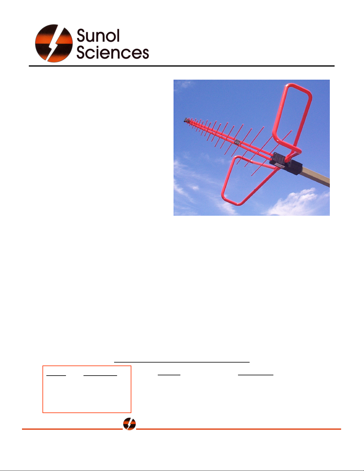
JB Series antennas are compact, highperformance instruments designed for
EMC emissions and immunity testing.
The broadband characteristics of these antennas enable them to operate over a wide
frequency range - a must for automated test environments. Innovative design and
manufacturing techniques result in long-lasting strength and mechanical integrity. The result is
an electrically stable measuring instrument that maintains calibration over extended use.
The antenna boom is made from a custom aluminum extrusion that reduces the number of
parts at the nose. The result is a stronger, more stable feedpoint and excellent crosspolarization properties. The unique shape allows for a larger feed cable to be used, which
significantly increases the maximum power rating. Dipole elements are permanently attached
to the boom by an assembly technique that maintains excellent electrical characteristics for the
life of the antenna.
The low-frequency wings are swept forward and turned in at the ends to reduce ground plane
coupling while maintaining performance. Each wing is attached with dual compression fittings
for true alignment. A tough powdercoat finish with UV inhibitors seals the aluminum structure
and protects it from sunlight and moisture.
Model
JB1
JB3
JB5
JB6
Frequency
30 - 2000 MHz
30 - 3000 MHz
30 - 5000 MHz
30 - 6000 MHz
Includes Individual A2LA accredited calibration
Options
• Sunol SNAP! mount
• Tripod mount
• Carrying case
Sunol Sciences Corporation
Model JB1
Applications
• Radiated emissions
• Radiated immunity
• Pre-scan / Full-compliance
30 MHz – 6 GHz
6780 Sierra Court, Suite R • Dublin, California 94568 • Tel: (925) 833-9936 • Fax: (925) 833-9059
info@sunolsciences.com • www.sunolsciences.com
Page 2
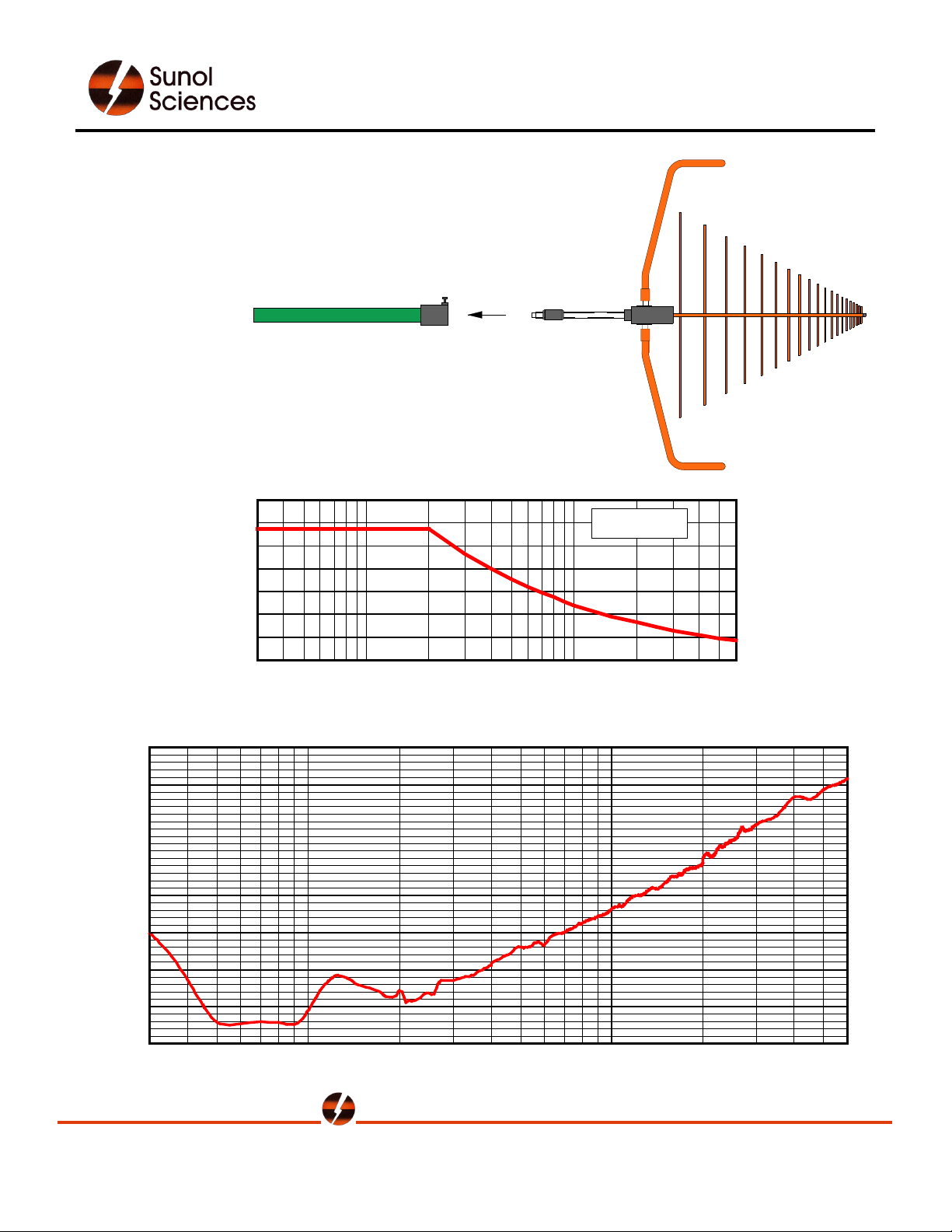
Mounting
All Sunol antennas have a 22 mm stainless steel rear mounting
tube. This configuration enables polarization changes without
vertical displacement of the antenna, and minimizes the effect of
the RF cable by keeping it well behind the antenna elements.
UICK
• Q
ECURE
• S
• N
O UNWANTED ROTATION
TOWER BOOM
SNAP!
MOUNT
The Sunol SNAP! mount provides a secure interface to most
antenna positioning towers. It locks the antenna in place,
prevents unwanted rotation and facilitates rapid antenna changes.
1400
1200
1000
800
600
400
200
Max. Input Power (watts)
0
30 50 70
100 200 300 500 700 2000 3000 60001000
Frequency (MHz)
JB Series Antennas (cont.)
MAX POWER
Typical E-field Antenna Factor, JB Series Antennas
45
40
35
30
25
20
Antenna Factor (dB)
15
10
5
30 50
70 100 200 300 500 700 1000 2000 3000 6000
Frequency (MHz)
Sunol Sciences Corporation
6780 Sierra Court, Suite R • Dublin, California 94568 • Tel: (925) 833-9936 • Fax: (925) 833-9059
info@sunolsciences.com • www.sunolsciences.com
Page 3

JB Series Antennas
Radiation Patterns
180°
30 MHz
90°
°
0
2
1
°
0
5
1
°
0
1
2
°
0
4
2
270°
6
0
°
3
0
°
0°
-20-30
0
0
°
0 dB-3-10
3
3
0
°
3
E-Plane
H-Plane
180°
°
0
5
1
°
0
1
2
0
2
1
°
0
4
90 MHz
90°
°
0
2
1
6
0
°
0
2
1
°
2
°
50 MHz
90°
270°
150 MHz
90°
6
0
°
3
0
°
0°
-20-30
0
0
°
0 dB-3-10
3
3
0
°
3
6
0
°
180°
°
0
5
1
-20-30
°
0
1
2
°
0
4
2
270°
0
0
°
3
0
°
0°
0 dB-3-10
3
3
0
°
3
180°
°
0
5
1
-20-30
°
0
1
2
°
0
4
2
270°
0
0
°
3
0
°
0 dB-3-10
3
3
0
°
3
Sunol Sciences Corporation
6780 Sierra Court, Suite R • Dublin, California 94568 • Tel: (925) 833-9936 • Fax: (925) 833-9059
info@sunolsciences.com • www.sunolsciences.com
0°
Page 4

JB Series Antennas
Radiation Patterns
180°
200 MHz
90°
°
0
2
1
°
0
5
1
°
0
1
2
°
0
4
2
270°
6
0
°
3
0
°
0°
-20-30
0
0
°
0 dB-3-10
3
3
0
°
3
E-Plane
H-Plane
180°
°
0
5
1
°
0
1
2
0
2
1
°
0
500 MHz
90°
°
0
2
1
6
0
°
0
2
1
°
4
2
°
250 MHz
90°
270°
1000 MHz
90°
6
0
°
3
0
°
0°
-20-30
0
0
°
0 dB-3-10
3
3
0
°
3
6
0
°
180°
°
0
5
1
-20-30
°
0
1
2
°
0
4
2
270°
0
0
°
3
0
°
0°
0 dB-3-10
3
3
0
°
3
180°
°
0
5
1
-20-30
°
0
1
2
°
0
4
2
270°
0
0
°
3
0
°
0 dB-3-10
3
3
0
°
3
Sunol Sciences Corporation
6780 Sierra Court, Suite R • Dublin, California 94568 • Tel: (925) 833-9936 • Fax: (925) 833-9059
info@sunolsciences.com • www.sunolsciences.com
0°
Page 5

JB Series Antennas
Radiation Patterns
180°
1500 MHz
90°
°
0
2
1
°
0
5
1
°
0
1
2
°
0
4
2
270°
6
0
°
3
0
°
0°
-20-30
0
0
°
0 dB-3-10
3
3
0
°
3
E-Plane
H-Plane
180°
°
0
5
1
°
0
1
2
2
1
°
0
°
0
4
2
2000 MHz
90°
270°
6
0
°
3
0
°
0°
-20-30
0
0
°
0 dB-3-10
3
3
0
°
3
2500 MHz
90°
°
0
2
1
6
0
°
3
0
°
0°
0 dB-3-10
3
3
0
°
3
180°
°
0
5
1
-20-30
°
0
1
2
°
0
4
2
270°
0
0
°
Sunol Sciences Corporation
6780 Sierra Court, Suite R • Dublin, California 94568 • Tel: (925) 833-9936 • Fax: (925) 833-9059
info@sunolsciences.com • www.sunolsciences.com
 Loading...