

Page 1
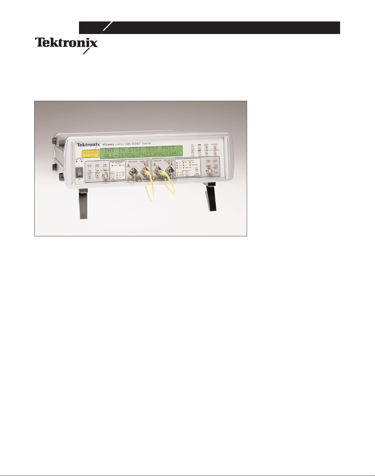
The ST2400A is the first
STM-16/OC-48 test product
optimized for testing
2.488 Gbit/s Dense Wavelength Division Multiplexed
(DWDM) client systems. Its
compact size, flexibility of
configuration, choice of operating modes, unique I/O features, extensive software
driver support, and range of
error and defect inject capabilities make it particularly
effective for DWDM system
test during production and
installation. It can also be
used in non-DWDM SDH and
SONET test applications.
The ST2400A is payloadindependent; external
SDH/SONET 155 Mbit/s
optical and electrical and
622 Mbit/s optical signals are
supported in add/drop mode.
The ST2400A can be ordered
as an ST2400A Transceiver,
as an ST2400R Receiver, or
as an ST2400T Transmitter to
meet a wide range of application needs economically.
The ST2400A Transceiver
version can transmit and
receive STM-16/OC-48 signals. The ST2400A has the
ability to receive, generate
and modify an STM-16c/
OC-48c signal. The transmitter section can internally generate a 2.4 Gb/s signal or
multiplex the higher-rate signal from STM-1 or STM-4
(OC-3 or OC-12) signal
inputs. The ST2400A can
also accept a STM-16/OC-48
signal in through mode and
regenerate it. The receiver
section receives an STM16/OC-48 signal, demultiplexes it, and can drop out
either the STM-1 or STM-4
(OC-3 or OC-12) signal as
required.
The Transmitter version can
generate and transmit the
STM-16/OC-48 signal from
an internal source, or multiplex the higher-rate signal
from either STM-1 or STM-4
(OC-3 or OC-12) signal
inputs. In the case of STM-4c
and STM-16c (OC-12c or
Copyright © 1999 Tektronix, Inc. All rights reserved.
ST2400A
STM-16/OC-48 2.4 Gbit/s Test
Set for DWDM Applications
Optimized for Dense Wavelength
Division Multiplexing (DWDM)
Transmission Quality Testing
Available in Transceiver, Receiver
and Transmitter Only Versions
Tributary Testing of STM-64/OC-192
Systems
Easily Switchable to/from
SDH/SONET
Optical Tributary Payload Add/Drop
with Payload Independence
External Sync Reference for Timing
Coordination
Active Through Mode to Simulate
Fault Conditions on Installed
Networks
Compact and Light Weight for
Production and Installation Test
A Variety of Optics Options,
Including No Optics
Emulates Network Elements
Transmitting Live Traffic
Page 2

page 2
OC-48c, the ST2400A can
either generate four STM-4c
(OC-12c) tributary signals
with PRBS payloads inside
an STM-16/OC-48 envelope,
or generate three tributary
payloads of PRBS STM-4c
(OC-12c) and insert a fourth
from outside the tributary
interface (which could contain IP traffic). In the case of
STM-16c/OC-48c, the entire
(single) payload is PRBS. All
applicable SDH/SONET Path
Pointer Bytes (H1/H2/H3) are
set correctly to indicate the
type of payload being carried
(STM-4c/STM-16c,
OC-12c/OC-48c, etc.).
The Receiver version can
receive and demultiplex the
STM-16/OC-48 signal and
drop either the STM-1 or
STM-4 (OC-3 or OC-12) signal to an auxiliary test set,
as required.
ST2400A can accept zero,
one or two factory-installed
2.488 Gb/s laser transmitter
modules and/or zero or one
APD receiver module (also
referred to as I/O modules).
One type of laser transmitter
– direct modulated (DM) – is
available.
The ST2400A provides electrical input and output clock
and data interfaces operating
at 2.488 Gb/s. Base
Transceiver configuration
provides 2.488 Gb/s electrical
interfaces and 155/622 Mb/s
optical and electrical
add/drop tributary interfaces.
Transmitter configurations do
not include 155/622 optical
and electrical drop interface.
Receiver configurations do
not include 155/622 optical
and electrical add interface.
The user can individually
enable/disable laser #1 (if
installed), laser #2 (if
installed), and electrical outputs. Multiple outputs can be
simultaneously active.
NOTE: RX will not measure
correctly if both TX lasers are
enabled and looped back to
RX (since RX contains broadband optical detector which
is not wavelength-selective).
Three Operating Modes
The ST2400A Transceiver
features three operating
modes to provide the flexibility you need to test today’s
advanced STM-16, OC-48,
STM-64, OC-192, and DWDM
systems. Analysis is done at
the SDH/SONET Regenerator
Section (Section), Multiplexer Section (Line) and
Path levels independent of
the payload.
Standalone (Internal) Mode
Where payload testing is not
required, or an external
155 or 622 Mbit/s tributary
signal is not available, the
ST2400A can operate independently. An internally-generated 2.488 Gbit/s test signal
provides full error performance analysis and reporting
of the 2.488 Gbit/s signal.
1.5 Mbit/s, 2 Mbit/s, and
2 MHz external reference
clock signals or an internal
clock signal can be used to
time the transmitted signal in
internal mode. Internal mode
is ideal for DWDM
SDH/SONET client system
testing, where transmission
quality test time and cost can
be lowered through the use of
a high-speed signal.
Active Through Mode
Through Mode allows overhead bytes to be passed or
edited while regenerating the
received 2.488 Gbit/s signal.
Alarms and errors can also be
added to the received signal
prior to retransmission. This
mode is especially valuable
for testing framing synchronization and protection
switching, and for diagnosing
system interoperability problems. 155 or 622 Mbit/s signals can be dropped from the
receiver for path level analysis on another tester.
Add/Drop (External) Mode
In this mode, the ST2400A
transmitter creates the 2.488
Gbit/s signal from an externally added 155 or 622
Mbit/s SDH or SONET signal.
The external signal can be
copied into one or all available payload envelopes in the
2.488 Gbit/s signal. The
ST2400A receiver performs
2.488 Gbit/s level testing and,
as required, drops a tributary
signal for path level analysis
by a Tektronix CTS 850, CTS
710, ST112, or any other 155
or 622 Mbit/s SDH or SONET
test set. Previous investment
in lower speed test equipment is preserved.
Emulation of Real SDH/SONET
Systems
The ST2400A provides two
features that let the tester
emulate real network conditions. First, a 2
23
-1 PRBS pattern can be generated to produce a synchronous signal
that behaves like live traffic.
Second, the optical receiver’s
decision threshold can be offset to emulate older
SDH/SONET network elements that are deployed in
the field and which can create interoperability issues
when connected to optically
amplified systems such as
DWDM. By controlling what
the ST2400A considers a
“one” or a “zero,” true system transmission quality can
be determined; installed
behavior predicted; and, optimized in the factory.
DWDM Parallel Channel Test
Because DWDM systems carrying SDH/SONET clients are
expected to operate at a transmission quality level of
10
–12
BER or better per ITU-T
G.692 and Bellcore GR2918,per channel transmission quality test cycles can
easily exceed twelve hours.
By testing all channels in parallel, system test time can
remain constant as channel
counts increase from eight to
sixteen to thirty two and
beyond. The ST2400R
Receiver provides the means
for highly cost-effective
simultaneous multi-channel
analysis. A Receiver can measure the transmission performance of each channel of the
multi-wavelength system,
while a ST2400T Transmitter
Page 3
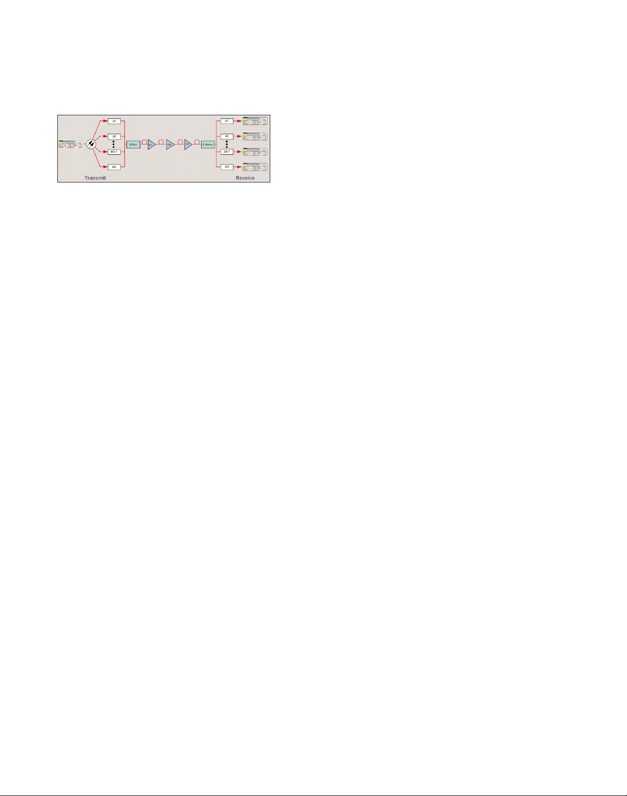
page 3
is used to generate the
2.488 Gbit/s signal, which
can be split to multiple
inputs of the DWDM system.
The Parallel Channel Test is
illustrated in the figure
below.
Help in Lowering per Channel
Test Time
In addition to using the
ST2400A for effective parallel channel test, the product
can also help lower per-channel test time.
Accelerating Low BER Measurement
through Extrapolation
Measuring the low error rates
that DWDM systems promise
can take a minimum of 11
hours at 2.488 Gbit/s. The
ST2400A provides a way in
some applications to save test
time by extrapolating to low
BERs through offset of the
optical receiver’s decision
threshold.
Improved Test Convenience
If the system has been characterized in design, then many
of these tests need not be
repeated further down the
value chain. The power of the
ST2400A is focused on system transmission quality verification during production
and installation. For production test, a full remote command set plus LabView™and
LabWindows™CVI, HP-VEE
™
drivers help manufacturing
engineers create automated
test suites quickly and efficiently. A "pause" feature
enables tests to be suspended
while rearrangements are
made, which allow long-term
testing to proceed. Tests can
also be automatically
resumed after lost power is
restored, again saving retest
time. Finally, by using the
ST2400A in constant wavelength (unmodulated) mode,
optical tests such as OSNR
and spectral width can be
done without the need for an
additional laser source.
2.488 Gbit/s Interface Choices
For manufacturers and
installers of DWDM equipment, the ST2400A offers a
low-dispersion, long reach
1550 nm laser option that
provides enhanced performance. In addition, the lowdispersion optics can be
ordered at specific ITU-T
G.692 grid frequencies to
meet precise requirements. If
low-dispersion optics are not
required, the ST2400A longreach 1310 nm optics can be
ordered. A dual
1310/1550 nm wavelength
option is provided for customers who need flexibility.
Finally, a customer can
choose to configure units
with only 2.488 Gbit/s electrical I/O. This feature is provided for applications such
as laser-driver module tests
where optics are not
required.
± 1 nm Wavelength Tuning
The ST2400A provides the
capability to “tune” the
wavelength of its 1550 nm
laser from its nominal value
up or down by one nanometer. This feature allows the
user to check adjacent channels on the G.692 frequency
grid without purchasing
additional specific wavelength lasers. This feature
would typically be useful in
testing DWDM systems without transponders or in testing
transponder-based systems
when the transponder is not
part of the test set up.
STM-64/OC-192 Tributary Testing
Testing 10 Gbit/s systems at
the line rate requires very
expensive test equipment.
These systems can be tested
more economically at the
2.488 Gbit/s tributary rate
using the ST2400A.
Adheres To The Latest Standards
The ST2400A complies with
the latest ITU-T, ANSI, ETSI,
and Bellcore recommendations and standards.
Capabilities
• STM-16 SDH RS and MS
Testing/OC-48 SONET Section and Line Testing
– B1, B2, B3 Error
Generation
– B1, B2, B3 Error
Measurement
– Path REI, Path Alarms,
Pattern Bit Error
– J0, J1 Capture and J0 Edit
– RS and MS Alarm
Generation
– RS and MS Alarm
Detection
– RS and MS Layer Alarm
and Error Generation
• VC4 PRBS Mappings/STS1,
STS3c PRBS Mappings
• Ability to receive, generate
and modify an STM4c/STM-16c (OC-12c/
OC-48c) Payload (Opt. 41)
• External Clock Input
(2 Mbps/2 MHz) or
1.5 Mbps
• User-selectable power failure recovery mode
• Electrical Offset of Receiver
Decision Threshold
• ±1 nm wavelength tuning
(applies only to 1550 nm
lasers)
• CW laser source mode
• 2.488 Gb/s electrical I/O
• 3-year warranty
• Automatic Optical Receiver
shut-off if power exceeds
maximum rating
• Specific wavelength G.692
lasers in 1550 nm region
• Portable – 11.4 kilograms
(25 pounds) maximum
weight
• A simple menu system
• Tributary Access at
155 Mb/s or 622 Mb/s
• Easily software switched
between SDH and SONET
• Integrates with the CTS 750
or CTS 850 or ST112 for
complete “all-rate” SDH or
SONET analysis
• Wide optical range:
– 3 dBm to –2 dBm Typical
Output Power
– -29 dBm to –10 dBm
Receiver Sensitivity
Page 4

page 4
ST2400A
Transmitter
Specifications
• Through Mode with Overhead Editing, Error, and
Alarm Injection
• Direct user download of
software updates
• CCITT/ITU G.708, G.709
and GR-253-CORE framing
• Complete Remote Control
– RS-232 and GPIB ports,
and standard printer
interfaces
– LabView, LabWindows
CVI, and HP Vee
• Standard tributary
interfaces
– STM-1e 155 electrical/
STS-3 155 electrical
– STM-1 155 optical/
OC-3 155 optical
– STM-4 622 optical/
OC-12 622 optical
• Interface to Regenerator
Section Terminating Element and Multiplexer Section Terminating Element
and other test equipment
With firmware version 5.0
(Opt. 42), the following new
features are added to capabilities of the ST2400A:
• Payload bit error injection/B3 Injection on the TX
side (TSE)
• B3, Path-REI, Payload bit
error count measurement
on the RX side (TSE ES,
SES (SDH only))
• Alarm signal status (RX)
– Path RDI, Loss of Pointer,
Path AIS, Path REI
• Path Overhead Monitor
(RX) – Displays value of
bytes: J1, B3, C2, G1, F2,
H4, Z3/F3, Z4, N1
• For the path overhead, C2
byte added at TX (Path Signal Label C2) – Identifies
High Order Path Label
Unequipped and High
Order Path Label Mismatch. C2 byte can be set to
any value from 0x00 to
0xFF.
• B3 Path Analysis/J1 Path
Trace (displayed as ASCII
text).
• TX Patterns. PRBS 231-1
and 231-1 Inverted; Fixed
(00 to FF)
• Pointers. Pointer Value displayed (0 to 782). Pointer
Measurement Counts for
Positive Pointer Justifications, Negative Pointer Justifications, New Data Flag
(NDF)
• Extended capability of
View History button
• APS Switch Time measurement (LOF, LOS durations).
APS testing can be performed by causing protection switch via control of
K1/K2 bytes and then
displaying time to restore
frame synchronization.
Highly-accurate LOF timer
enables this test to be
performed with <1 ms
resolution.
• RX mapping (PRBS 223-1
and 223-1 Inverted; PRBS
231-1 per ITU-T O.151 and
231-1 Inverted per ITU-T
O.181, User-defined byte
0x00 to 0xFF)
Applications
The ST2400A meets the
needs of development, manufacturing, and service engineers by providing the capabilities for:
• System interrogation and
conformance testing
• Manufacturing Production
Testing
• Network Integrity testing
• Network Performance
monitoring
• Network Troubleshooting
2.488 GBIT/S LONG REACH LASER OPTIONS
1310/1550 WAVELENGTH
1310 nm ± 6 nm/1550 nm ± 6 nm
Power – 0 dBm (typical).
Spectral Width – 1 nm modulated mode
(maximum), 0.3 nm (typical).
Wavelength Stability – < ± 0.1 nm
(minimum).
Wavelength Adjustment Range – > ± 1 nm
(uncalibrated).
Side Mode Suppression Ratio – 30 dB.
Output Power Variation, CW Mode –
± 0.1 dB (typical).
Output Power Variation, Between Modulated Mode and Unmodulated Mode –
± 0.5 dB (typical).
Extinction Ratio, Modulated Mode –
> 10 dB.
Optical Waveform – per ITU-T G.691/G.957
and Bellcore GR-253-CORE/GR-2918-CORE.
Safety Classification – Class IIIB per 21
CFR 1040.10; Class IIIA per IEC 825-1.
Category – SDH L-16.1/SONET LR-1.
1550 Dispersion Budget – 1800 ps/nm;
2 dB power penalty.
Category – SDH L-16.2/SONET LR-2.
2.488 GBIT/S ELECTRICAL OUTPUTS
Single-ended clock and data interfaces;
unterminated ECL; requires connection to
an AC-coupled 50 Ω termination through a
bias-tee network supplying current for the
ECL outputs; falling edge of output clock
coincides with data edge crossing ±100 ps;
SMA connectors. ECL specifications: At
high output voltage, 25°C, –0.98 V (min). At
low output voltage, 25°C, –1.95 V (min)
and –1.63 V (max).
TRIBUTARY ADD INTERFACE
Inputs monitored for LOS and LOF, status
displayed on front-panel LEDs.
155 Mbit/s Electrical:
75 Ω BNC CMI per ITU-T G.703 and
Bellcore GR-253-CORE.
155/622 Mbit/s Optical:
Wideband input: 1250 nm to 1600 nm.
Minimum sensitivity: –28 dBm at
10
–10
BER.
Overload limit: –8 dBm at 10
–10
BER per
ITU-T G.957 and Bellcore GR-253-CORE.
Page 5

page 5
ST2400A
Transmitter
Specifications
Continued
PAYLOAD GENERATION
2.488 Gbit/s signal framing and multiplexing format to meet ITU-T G.707 and
Bellcore GR-253-CORE.
Output Timing –
INT mode: Generated from internal
2.488 Gbit/s ±20 ppm clock or external
1.544 Mbit/s, 2.048 MHz, or 2.048
Mbit/s ref clock.
THRU mode: Generated from clock
recovered from 2.488 Gbit/s input.
EXT mode: Generated from clock, recovered from 155/622 Mbit/s add input.
OUTPUT SIGNAL STRUCTURE
1. Active THRU (Through) Mode
Regenerated with recomputed B1, B2 but
otherwise unaltered or with user-modified
overhead, added defects, or added errors
from the received 2.488 Gbit/s input signal
using the recovered clock. Jitter transfer
from 2.488 Gbit/s input to output is filtered
by a 1 MHz (nominal) bandwidth PLL
(typical 0.3 dB jitter transfer).
2. EXT (Terminal) Mode
155 or 622 Mbit/s tributary signals are
added from an external SDH or SONET test
set. 2.488 Gbit/s signal is generated using
clock recovered from the add input. Tributary signals added into any 1 of 16
(155 Mbit/s) or any 1 of 4 (622 Mbit/s) payload locations or duplicated to fill all payload locations. Unused payload locations
are VC-4 structured STM-1 (SDH mode)
STS-3C structured STS-3, or 3 x STS-1
(SONET mode) structured with unequipped
path overhead (J1=0, C2=0, correct B3,
remainder of path overhead =0). The
remainder of the channel payload is bulkfilled with user-selected test pattern (all
Zeros, ITU-T 0.181 223-1 PRBS, or 223-1
PRBS). In "all" mode, the tributary overhead
is copied to fill all the 2.488 Gbit/s overhead; in "single" mode, one copy is made for
the selected location and all other locations
are filled with "unequipped" channel overhead and user-selected test patterns (all
Zeros, ITU-T 0.181 2
23
-1 PRBS, or
223-1 PRBS).
3. INT (Standalone) Mode
2.488 Gbit/s signal is VC-4 structured STM1 (SDH), STS-3C structured STS-3, or 3 x
STS-1 (SONET) structured and filled with
test patterns as in External Mode. Default
overhead: A1 and A2 are set to F6H and
28H, respectively; J0 byte is set to 1; 15 Z0
bytes and 32 National Use bytes (formerly
C1 bytes) are numbered from 2 to 48 (decimal); H1 is set to 6AH and H2 is set to 0AH
for valid STS/STM pointers.
B1 contains computed B1 BIP and B2 contains computed B2 BIP; all other overhead
set to 00H.
J1 and C2 in path overhead set to 0. B3 BIP
set to correctly computed parity. All other
path overhead set to 00.
OVERHEAD EDITING
Overhead bytes in STS-1, column 1 can be
independently set as hex values in the range
00 to FF.
Settable bytes: J0, E1, F1, D1-D3, K1, K2,
D4-D12, S1, M1, E2.
Following bytes may not be directly edited:
A1, A2, B1, B2, B3, H1-H3.
Clear-text coding and dedicated menus for
S1 (Synchronization Status Byte) and K1/K2
(MSP – Multiplex Section Protection/APS
– Automatic Protection Switching).
Active THRU (Through) Mode: Overhead
bytes are regenerated from the 2.488 Gbit/s
input and can be selectively overwritten.
B1 and B2 are recalculated prior to
transmission.
EXT (Terminal) Mode: All bytes except for
B1 are inserted from the tributary into one
or all envelopes. Settable bytes can be
selectively overwritten. B1 and B2 are recalculated prior to transmission.
INT (Standalone) Mode: All bytes are generated internally. Settable bytes can be selectively overwritten.
DEFECT/ALARM GENERATION – LOS, LOF, MS-AIS/AIS-L,
MS-RDI/RDI-L
Multiple defects and alarms can be set for
simulation of real network conditions.
Duration Control –
LOS: 1 to 127 µs (1µs resolution).
LOF, MS-AIS/AIS-L, MS-RDI/ RDI-L: 1 to
127 frames (1 frame resolution).
All: 0.1 to 9.9 s (0.1 s resolution).
Continuous or off.
Interval Control: Repeat On/Off.
Injection time: 0.1 to 9.9 s.
Idle time: 1.0 to 30 s.
Resolution (all): 0.1 s.
ERROR GENERATION B1, MS-REI/REI-L, BIT
Error Control –
B1 (BIP-8): Single error or continuous error
rate, 2.5E-5 to 0.1E-9.
B2 (BIP-24): Single error in one or all
channels or continuous error rate, 1.0E-3
to 0.1E-9.
B3: Single error in one or all channels or
continuous error rate 1.0E-3 to 0.1E-9.
MS-REI/ REI-L: M1 byte is overwritten. 0 to
255 errors per frame inserted in a single
frame, continuously, or for a duration of 0.1
to 9.9 s; Resolution, 0.1 s.
Bit errors in selected STM-1/STS-1 tributary
or across 2.488 Gbit/s frame.
Single error or continuous error rates,
1.0E-3 to 0.1E-9.
Interval Control: Repeat On/Off.
Injection time: 0.1 to 9.9 s.
Idle time: 1.0 to 30 s.
Resolution (all) : 0.1 s.
Other Interfaces –
Clock Sync Output: 1/8 rate, AC-coupled,
300 mV
p-p
(minimum), SMA connector.
Frame Sync Output: 50 Ω, ECL, 25.8 ns
pulse width, BNC connector.
Event Trigger Output: 50 Ω, TTL, 25.8 ns
pulse width, BNC connector.
Pulse transmitted for each alarm, error, or
overhead event (selectable).
Page 6

ST2400A
Receiver
Specifications
page 6
2.488 GBIT/S OPTICAL RECEIVER:
Type – InGaAs APD.
Input tolerance – ±20 ppm.
Wavelength – 1250-1600 nm.
Sensitivity – -28 dBm minimum at
10
–12
BER.
Overload – -10 dBm at 10
–12
BER.
Input reflectance – Better than –27 dBm.
Threshold offset – 100 settings, uncali-
brated. Initial setting optimized by factory
Range: ± 150 mV (typical).
2.488 GBIT/S ELECTRICAL INPUTS
AC-coupled 50 Ω terminated ECL clock and
data interfaces; allow ST2400A to operate
error-free when electrical outputs are
looped to electrical inputs through a biastee termination; data valid when sampled
within ±50 ps of center of data eye; SMA
connectors. ECL specifications: At high
input voltage, 25°C, –0.98 V (min). At low
input voltage, 25°C, –1.95 V (min)
and –1.63 V (max).
RECEIVER TIMING
Analyzer Clock Recovery –
Input Frequency Range: 2.48832 Gb/s
±20 ppm.
Input Jitter Tolerance: Meets Bellcore
GR-253-CORE and ITU G.825.
155/622 Mbit/s Output Timing – Derived by
dividing the clock recovered from the
Analyzer 2.488 Gb/s input.
Tributary Drop Interfaces – Allows payload
analysis using an external test set such as
the Tektronix CTS 850, CTS 710, or ST112.
155 Mbit/s Electrical:
75 Ω BNC CMI per ITU-T G.703 and
Bellcore GR-253-CORE (at 25°C ±5°C).
155/622 Mbit/s Optical:
Wavelength: 1310 nm (1273-1355 nm).
Minimum average power: –15 dBm.
Maximum average power: –8 dBm.
Category: I-4.1/IR-1.
Type: Class 1 laser per IEC 825-1 and
21CFR 1040.
PAYLOAD ACCESS
A selected tributary (1 of 16 155 Mbit/s or 1
of 4 622 Mbit/s) is dropped to an external
SDH or SONET test set, using the clock
recovered from the 2.488 Gbit/s input. Drop
Overhead: B1, B2 are recalculated; H1-H3
are copied from the selected channel. For
155 Mbit/s signal, the remainder of overhead is copied from the first three columns
of the 2.488 Gbit/s input. For 622 Mbit/s
signal, the first three columns of the drop
signal are copied from the first three
columns of the 2.488 Gbit/s signal; the last
nine columns of the remainder are copied
from the selected drop channel.
Jitter transfer from 2.488 Gbit/s receiver to
drop interface is filtered by a 1 MHz
(nominal) bandwidth PLL, and divided down
to the drop rate.
Overhead Display: 2.488 Gbit/s, column 1 of
the first STM-1 or STS-3/3c transport overhead bytes can be displayed as hex values.
Displayed bytes: A1, A2, B1, E1, F1, D1-D3,
H1-H3, B2, K1, K2, D4-D12, S1, E2. Cleartext decoding (for easy interpretation of
G.707/GR-253-CORE message codes): S1
(Synchronization Status Byte), K1/K2 bytes
(APS – Automatic Protection
Switching/MSP – Multiplex Section
Protection).
Defect and Alarm Measurement: LOS, LOF,
OOF, AIS, MS-RDI/RDI-L. Status: Displayed
as front-panel LEDs with "history" button.
ERROR MEASUREMENT
SDH: B1, B2, B3, MS-REI per G.821 and
G.826; unavailability per G.827. Errored
Blocks, Errored Seconds, Severely Errored
Seconds, Unavailable Ratio, Unavailable
Seconds, Errored Seconds Ratio, Severely
Errored Seconds Ratio, Consecutive
Severely Errored Second Periods, Background Block Errors, Background Block
Error Ratio, Total Count, Available Errored
Blocks, Available Errored Seconds, Available
Background Block Errors, Available Severely
Errored Seconds, BER.
SONET: B1, B2, B3, REI-L per GR-253CORE. Errored Seconds, Severely Errored
Seconds, BER, Total Count.
B1, B2, MS-REI/REI-L Status: Displayed as
front panels LEDs with "history" button.
ERROR REPORTING
Test Period –
Manual start/stop, timed start/stop, and
repeated gate.
Duration: 1 s to 99 days.
Resolution: 1 s.
Report Printout –
Comprehensive printout of alarms, errors,
performance analysis, test start/stop/
pause time.
Print on event, at end of test, both, or on
demand.
Event Log –
Previous tests held in memory for subsequent printing.
Alarms, error counts and S1 (SSM) byte
changes logged per second, output to
printer or PC as required.
REMOTE CONTROL
Interfaces –
IEEE-488.2 (GPIB) and RS-232.
Command Set: High-level ASCII.
Printer –
Interface: DB-25 translation of Centronics.
Signal: TTL.
Description: Byte serial ASCII printer interface. Follows industry standard.
Connector: DB-25.
Drivers –
National Instruments LabWindows CVI or
LabView; Hewlett-Packard HP-VEE.
EXTERNAL REFERENCE TIMING INTERFACES
SDH: 2.048 Mbit/s or 2.048 MHz SETS input
per G.703, except that ST2400A input
requires ±40 ppm. BNC connector on front
panel.
SONET: 1.544 Mbit/s BITS input per ANSI
T1.101-1994, except that ST2400A input
requires ±40 ppm. Bantam connector on
rear panel.
Page 7

page 7
ST2400A
General
Characteristics
ENVIRONMENTAL
Temperature –
Operating: 0 to +40°C.
Nonoperating: –20 to +60°C.
Electromagnetic Compatibility –
EC Council Directive 89/336/EEC. Low
Voltage Directive 73/23/EEC.
Emissions Standard EN50081-1: Class A
for radiated and conducted emissions.
Laser Safety –
Laser output keyswitch interlock, remote
interlock, and front-panel LED indication
ensure operator safety.
2.488 Gbit/s optical output: Class IIIA per
IEC 825-1; Class IIIB per 21 CFR 1040.
155/622 Mbit/s optical output: Class I per
IEC 825-1 and 21 CFR 1040.
Power –
Source Power
Voltage Requirements (auto-ranging):
110 (90 to 135) VAC or 220 (180 to
270) VAC.
Line Frequency: 47 to 63 Hz.
Power Consumption: 250 Watts maximum.
CONNECTORS
Optical Connectors – Customer choice of
one (1): FC/PC, SC/PC, or ST/PC.
PHYSICAL CHARACTERISTICS
Dimensions cm in
Height 11.6 4.5
Width 37.2 14.5
Depth 44.9 17.5
Weight kg lb
Net 11.4 25
Recommended Calibration Interval –
1 year.
Standard Warranty – 3 years parts and
labor.
Page 8

ST2400A
Ordering
Information
ST2400A STM-16/OC-48 SDH/SONET Transceiver
Includes: 2.488 Gbit/s Transmitter and
Receiver with electrical clock and data, tributary add/drop, power cord, user manual.
Opt. 13 – Add wideband receive optics and
1310 nm intermediate-reach 2.488 Gbit/s
laser.
Opt. 15 – Add wideband receive optics and
1550 nm long-reach 2.488 Gbit/s laser.
Opt. 17 – Add wideband receive optics and
switchable 1310 nm intermediate-reach and
1550 nm long-reach 2.488 Gbit/s lasers.
Opt. 35 – Add wideband receive optics and
1550 nm G.692 specific frequency longreach 2.488 Gbit/s laser.
Opt. 41 – Add STM-16C/OC-48C payloads.
Opt. 42 – Add B3 path analysis.
ST2400R STM-16/OC-48 SDH/SONET Receiver
Includes: 2.488 Gbit/s Receiver with electri-
cal clock and data, tributary drop, power
cord, user manual.
Opt. 11 – Add wideband receive optics.
Opt. 42 – Add B3 path analysis.
ST2400T STM-16/OC-48 SDH/SONET Transmitter
Includes: 2.488 Gbit/s Transmitter with
electrical clock and data, tributary add,
power cord, user manual.
Opt. 13 – Add 1310 nm intermediate-reach
2.488 Gbit/s laser.
Opt. 15 – Add 1550 nm long-reach
2.488 Gbit/s laser.
Opt. 17 – Add switchable 1310 nm interme-
diate-reach and 1550 nm long-reach
2.488 Gbit/s lasers.
Opt. 35 – Add 1550 nm G.692 specific fre-
quency long-reach 2.488 Gbit/s laser.
Opt. 41 – Add STM-16C/OC-48C payloads.
Opt. 42 – Add B3 path analysis.
ST2400A, ST2400R, and ST2400T Common Options
Opt. 01 – FC/PC optical connectors
(Opt. 01, 02, or 03 must be chosen).
Opt. 02 – SC/PC optical connectors
(Opt. 01, 02, or 03 must be chosen).
Opt. 03 – ST/PC optical connectors
(Opt. 01, 02, or 03 must be chosen).
Opt. 05 – Rack mount.
Opt. 06 – FC/PC 15 dB attenuator for
2.488 Gbit/s receiver.
Opt. 07 – SC/PC 15 dB attentuator.
Opt. 08 – ST/PC 15 dB attentuator.
Opt. C3 – Three year calibration service.
Opt. C5 – Five year calibration service.
Opt. D3 – Three year calibration data report.
Opt. D5 – Five year calibration data report.
Opt. R5 – Extended warranty to five years.
Related SDH/ SONET Test Products
CTS 850 – SDH/PDH/Jitter/Wander Test Set
for E1 to STM-4/4c.
CTS 710 – SONET/DS3/DS1 Test Set for
DS1 to OC-12.
ST112 – SONET/DS3/DS1 Test Set for DS1
to OC-12/12c. Includes TroubleScan software that interoperates with ST2400A in
SONET mode.
SJ300E – SDH/SONET Jitter Analyzer
Portable jitter analyzer for 52 Mbit/s,
155 Mbit/s, and 622 Mbit/s.
CSA803C – Communications Signal Analyzer: Eye pattern analyzer offering
STM-1/OC-3 to STM-64/OC-192 eye
patterns.
11801C – Digital Sampling Oscilloscope.
ORR24 – 2.488 Gb/s Optical Reference
Receiver.
OA5002 – Optical Attenuator.
Q8347 – Optical Spectrum Analyzer
(N. America only).
Q8221 – Optical Power Meter
(N. America only).
TQ8325 – Optical Wavelength Meter
(N. America only).
International Power Plug Options
Opt A1 – 220 V, Universal Euro 220 V,
50 Hz.
Opt A2 – 240 V, United Kingdom 240 V,
50 Hz.
Opt A3 – 240 V, Australian 240 V, 50 Hz.
Opt A4 – 240 V, 240 V, 60 Hz.
Opt A5 – 220 V, 220 V, 50 Hz.
Recommended Accessories
1 m BNC-to-BNC 75 Ω Coaxial Cable –
Order 012-1338-00.
Adaptor Plug, BNC-1.6/5.6 – Order
013-0300-00.
2 m FC-PC to FC-PC Optical Patchcord –
Order 174-1387-00.
9 ft. 25-pin DB25 Male to 9-pin DB9
Female RS-232 Cable – Order
012-1298-00.
AMP 06-0033 FC Style Build Out Attenuator, 15 dB Fixed Value – Order
119-5610-00.
Rackmount Kit – Order 016-1407-00.
Hardside Transit Case – Order
016-1494-00.
6/99 HB/XBS 2RW-11123-4
Copyright © 1999, Tektronix, Inc. All rights reserved. Tektronix products are covered by U.S. and foreign patents, issued and pending. Information in this
publication supersedes that in all previously published material. Specification and price change privileges reserved. TEKTRONIX and TEK are registered
trademarks of Tektronix, Inc. All other trade names referenced are the service marks, trademarks or registered trademarks of their respective companies.
For further information, contact Tektronix:
Worldwide Web: for the most up-to-date product information visit our web site at: www.tektronix.com
ASEAN Countries (65) 356-3900; Australia & New Zealand 61 (2) 9888-0100; Austria, Central Eastern Europe, Greece, Turkey, Malta,& Cyprus +43 2236 8092 0; Belgium +32 (2) 715 89 70;
Brazil and South America 55 (11) 3741-8360; Canada 1 (800) 661-5625; Denmark +45 (44) 850 700; Finland +358 (9) 4783 400; France & North Africa +33 1 69 86 81 81; Germany + 49 (221) 94 77 400;
Hong Kong (852) 2585-6688; India (91) 80-2275577; Italy +39 (2) 25086 501; Japan (Sony/Tektronix Corporation) 81 (3) 3448-3111; Mexico, Central America, & Caribbean 52 (5) 666-6333;
The Netherlands +31 23 56 95555; Norway +47 22 07 07 00; People’s Republic of China 86 (10) 6235 1230; Republic of Korea 82 (2) 528-5299; South Africa (27 11)651-5222; Spain & Portugal +34 91 372 6000;
Sweden +46 8 477 65 00; Switzerland +41 (41) 729 36 40; Taiwan 886 (2) 2722-9622; United Kingdom & Eire +44 (0)1628 403300; USA 1 (800) 426-2200.
From other areas, contact: Tektronix, Inc. Export Sales, P.O. Box 500, M/S 50-255, Beaverton, Oregon 97077-0001, USA 1 (503) 627-6877.
 Loading...