

Page 1
Low-Noise Voltage Preamplifier
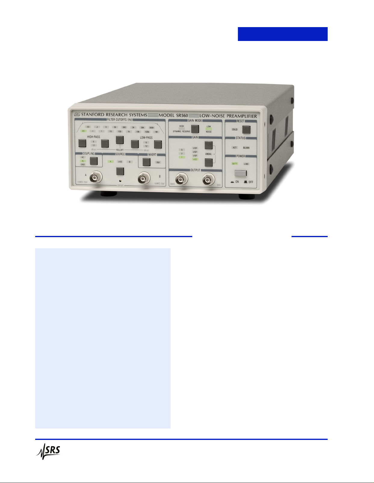
SR560 — DC to 1 MHz voltage preamplifier
· 4 nV/√Hz input noise
· 1 MHz bandwidth
· Variable gain from 1 to 50,000
· AC or DC coupled
· Two configurable signal filters
· Differential and single-ended inputs
· Line or battery operation
· RS-232 interface
· SR560 ... $2595 (U.S. list)
SR560 Low-Noise Preamplifier
The SR560 is a high-performance, low-noise preamplifier
that is ideal for a wide range of applications including
temperature measurements, optical detection, and
audio
engineering.
Inputs
The SR560 has a differential front-end with 4 nV/√Hz input
noise and an input impedance of 100 MΩ. Complete noise
figure contours are shown in the SR560 Tech Note at the
end of this section. The SR560’s inputs are fully floating
(BNC shields are not connected to chassis ground). Both the
amplifier ground and the chassis ground are available on the
rear panel for flexibility in grounding the instrument. Input
offset nulling is accomplished by a front-panel potentiometer,
accessible with a small screwdriver.
In addition to the signal inputs, a rear-panel TTL blanking
input lets you quickly turn off and on the instrument’s gain.
This is useful in preventing front-end overloading. The gain
turns off 5 µs after the TTL level goes high, and back on again
within 10 µs after the TTL signal goes low.
Outputs
Two insulated output BNC connectors provide 600 Ω and
50 Ω outputs. Both are capable of driving 10 Vpp into
their respective loads. Two rear-panel power supply outputs
low
Stanford Research Systems
phone: (408)744-9040
www.thinkSRS.com
Page 2
SR560 Low-Noise Preamplifier
provide up to 200 mA of ±12 VDC referenced to the amplifier
ground. The outputs provide clean DC power for use as a
bias
source.
Gain
Gain is selectable from 1 to 50,000 in a 1-2-5 sequence.
An adjustable gain feature lets you specify the gain as a
percentage of any of the fixed gain settings with 0.5 %
resolution. Gain can be selectively allocated before the filters
to optimize noise performance, or after the filters to reduce
susceptibility to overloads.
Filters
The SR560 contains two first-order RC filters whose cutoff
frequency and type (HPF or LPF) can be configured from the
front panel. Together, the filters can be configured as a 6 or
12 dB/oct rolloff low-pass or high-pass filter, or as a 6 dB/oct
rolloff band-pass filter. A filter reset button is included to shorten
the overload recovery time of the instrument when long filter
time constants are being used. Filter cutoff frequencies can be set
in a 1-3-10 sequence from 0.03 Hz to 1 MHz.
Battery Operation
Three rechargeable lead-acid batteries provide up to 15 hours
of battery powered operation. An internal battery charger
automatically charges the batteries when the unit is connected
to the line. The charger senses the battery state and adjusts
the charging rate accordingly. Two rear-panel LEDs indicate
the charge state of the batteries. When the batteries become
discharged, they are automatically disconnected from the
amplifier circuit to avoid battery damage.
No Digital Noise
The microprocessor that runs the SR560 is “asleep” except
during the brief interval it takes to change the instrument’s
setup. This ensures that no digital noise will contaminate lowlevel analog signals.
RS-232 Interface
The RS-232 interface allows listen-only communication with
the SR560 at 9600 baud. Up to four SR560s can be controlled
from a single computer, with each SR560 being assigned a
unique address. A “Listen” command specifies which SR560
will respond to commands on the RS-232 line. All functions
of the instrument (except power on) can be set via the RS-232
interface. The RS-232 interface is opto-isolated from the
amplifier circuitry to provide maximum noise immunity.
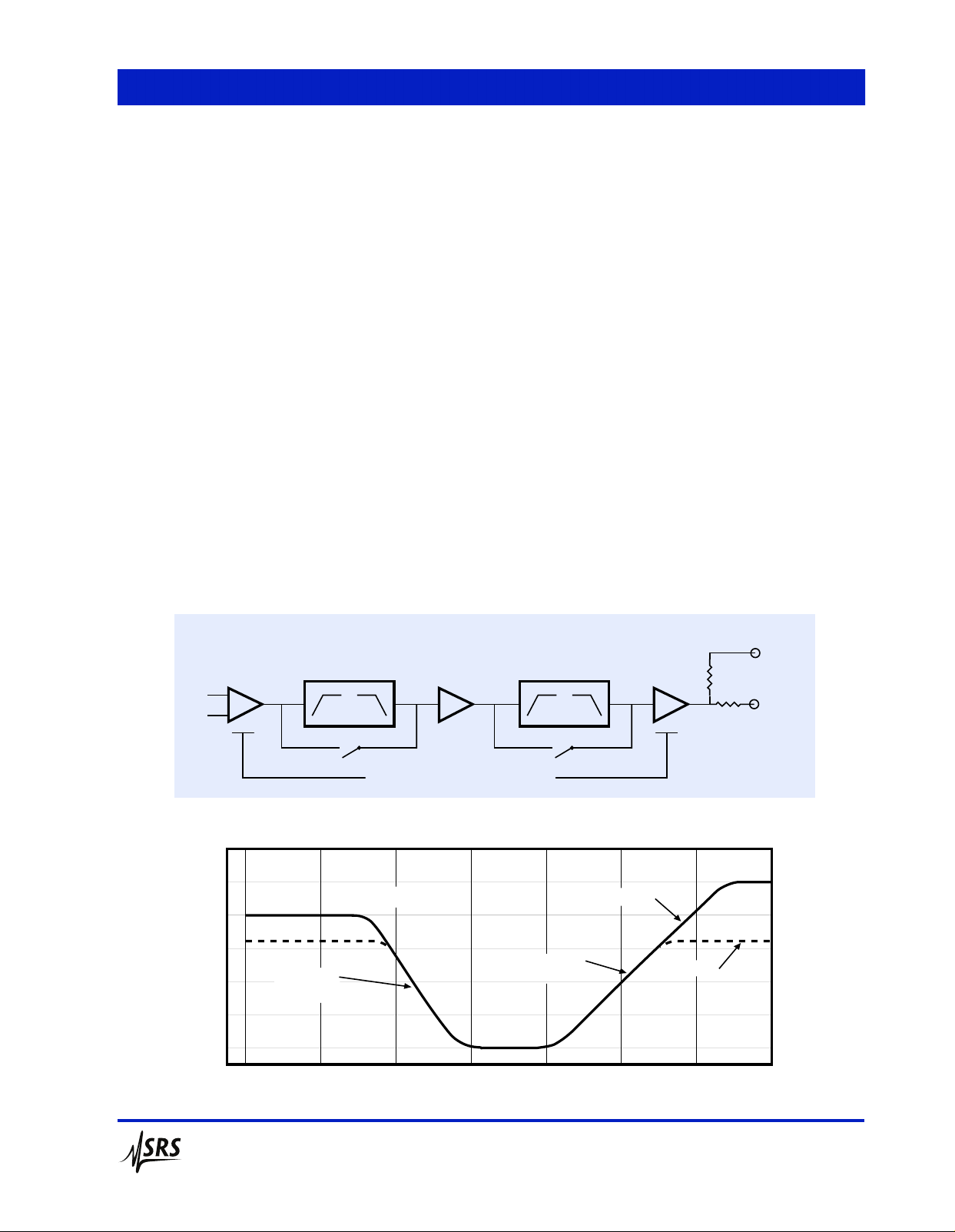
Dynamic Reserve
A
B
50 dB
40 dB
30 dB
20 dB
10 dB
0 dB
Front End
PREAMPLIFIER BLOCK DIAGRAM
Signal
Amplifier
Filter 1
DYNAMIC RESERVE ALLOCATION
Filter 2
Dynamic reserve vs. frequency
A =1000
v
BPF 1 kHz - 10 kHz
6 dB/octave
20 dB/decade
(due to HPF)
10 Hz1 Hz 100 Hz 1 kHz 10 kHz 100 kHz 1 MHz 10 MHz
Frequency
High Dynamic Reserve
6 dB/octave
20 dB/decade
(due to LPF)
Output
Amplifier
Low Noise
600Ω
50Ω
Outputs
3 V
1 V
100 mV
10 mV
Stanford Research Systems
phone: (408)744-9040
www.thinkSRS.com
Page 3

SR560 Specifications
Input
Inputs AC or DC coupled, single-ended
or differential
Input impedance 100 MΩ + 25 pF
Maximum input 3 Vpp
CMRR 100 dB from DC to 1 kHz
(100 mV common mode input at
1 kHz, gain of 100, low noise mode.
Decreases by 6 dB/octave from
1 kHz to 1 MHz)
Noise 4 nV/√Hz at 1 kHz
Gain 1 to 50,000 in 1-2-5 sequence
Vernier gain in 0.5 % steps
Gain stability 200 ppm/°C
Bandwidth –3 dB at 1.2 MHz (typ.)
Flatness ±0.3 dB to 300 kHz
(gains up to 1000)
Filters
Signal filters 2 configurable (low-pass or high-
pass) 6 dB/oct rolloff filters.
–3 dB points are settable in a 1-3-10
sequence from 0.03 Hz to 1 MHz.
Gain allocation
High Dynamic Reserve — Gain is
increased after the signal filters to
prevent overloading.
Low Noise — Gain is increased
before the filters to improve
noise figure.
Distortion 0.01 % at 1 kHz
Rear panel ±12 VDC @ 200 mA referenced to
amplifier ground
General
External gating TTL input sets gain to zero
Interfaces RS-232, 9600 baud, receive only
Power
100/120/220/240 VAC, 6 W charged,
30 W while charging. Internal batteries
provide 15 hours of operation between
charges. Batteries are charged while
connected to the line.
Dimensions 8.3" × 3.5" × 13.0" (WHD)
Weight 15 lbs. (batteries installed)
Warranty One year parts and labor on defects
in materials and workmanship
Short Circuit Input Noise Voltage
100
10
nV/√Hz
Output
Maximum output 10 Vpp into 50 Ω and 600 Ω
Filter reset Long time constant filters may be
reset with front-panel button.
DC drift 5 µV/°C referred to input
(DC coupled)
Ordering Information
SR560 Low-noise voltage preamplifier $2595
O560RMD Double rack mount kit $100
O560RMS Single rack mount kit $100
O560SB Spare battery set (3 batteries) $200
SR560 rear panel
1
110 100 1000 10000
Frequency (Hz)
SR560 Noise Figure
8
10
7
10
6
10
5
10
4
10
3
10
2
10
SOURCE RESISTANCE IN OHMS AT 290K
10
1
11010
1 dB
.5 dB
.15 dB
.05 dB
2
FREQUENCY IN Hz
.05 dB
.15 dB
.5 dB
1 dB
3 dB
6 dB
10 dB
15 dB
20 dB
25 dB
3
10
3 dB
4
10
5
10
6
10
Stanford Research Systems
phone: (408)744-9040
www.thinkSRS.com
 Loading...