

Page 1
Data sheet
Version
05.00
June
2004
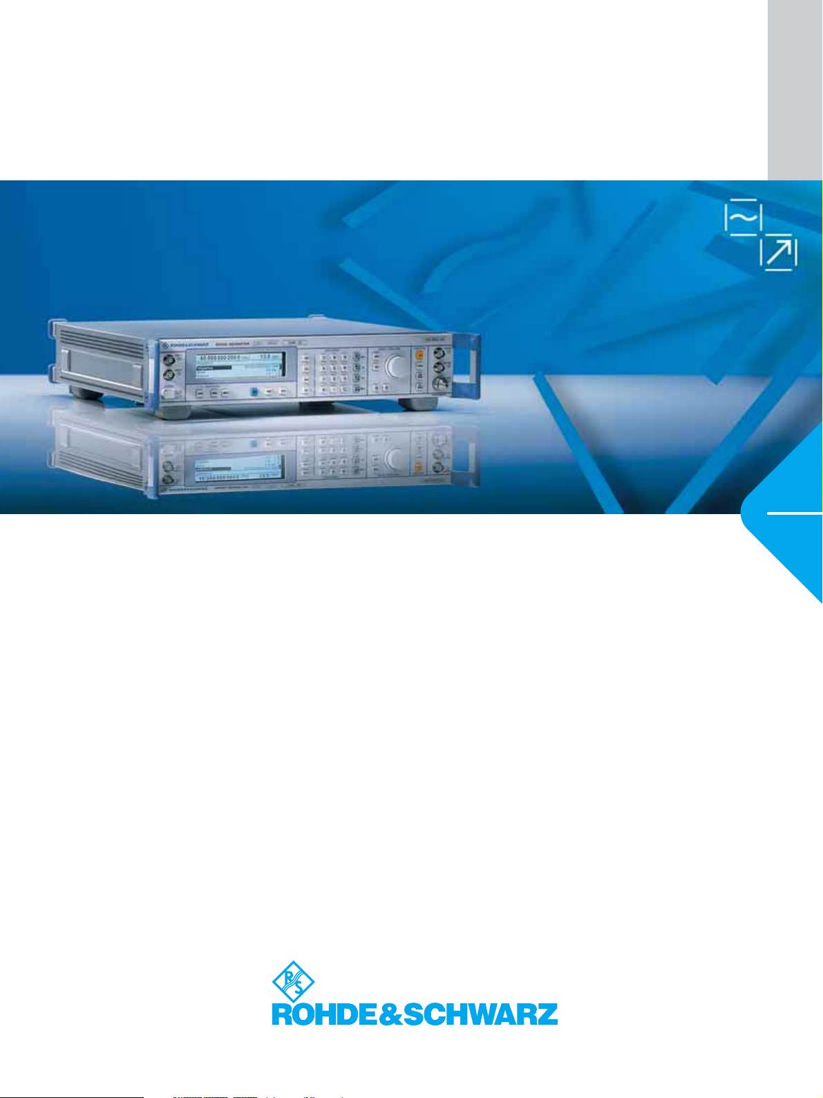
Microwave Signal Generator ¸SMR
High-performance, cost-effective and reliable up to 40 GHz
◆ Instrument family with four models
– ¸SMR20 (10 MHz to 20 GHz)
– ¸SMR27 (10 MHz to 27 GHz)
– ¸SMR30 (10 MHz to 30 GHz)
– ¸SMR40 (10 MHz to 40 GHz)
◆ Standard version:
CW generator with pulse modulation
and digital frequency sweep
◆ Easily upgradeable to AM/FM signal
generator and synthesized sweep
generator with analog ramp sweep
owing to flexible options concept
◆ Optional pulse generator for radar
and EMC applications
◆ Optional IF input for upconversion of
digitally modulated IF signals
◆ Compact, lightweight, user-friendly:
ideal in the lab and for field
applications
◆ 3-year calibration cycle
Page 2

The allrounder – designed for future-proofness
Ease of operation
◆ High-contrast LC display
◆ Online help including IEC/IEEE-bus
commands
◆ Simple and self-explanatory settings
◆ User-assignable keys
◆ One-hand operation with EasyWheel
Wide frequency range
◆ ¸SMR20 (1 GHz to 20 GHz)
◆ ¸SMR27 (1 GHz to 27 GHz)
◆ ¸SMR30 (1 GHz to 30 GHz)
◆ ¸SMR40 (1 GHz to 40 GHz)
◆ Optional extension of lower frequency
limit to 10 MHz (¸SMR-B11)
◆ Frequency resolution 1 kHz,
optional 0.1 Hz (¸SMR-B3)
High output power
◆ ¸SMR20 >+10 dBm (at 20 GHz)
◆ ¸SMR27
◆ ¸SMR30/40
(at 30/40 GHz)
>+11 dBm (at 27 GHz)
>+9 dBm
High-precision level control
◆ High-precision, frequency-response-
compensated level control
◆ Setting range extendible to
−130 dBm by means of the optional
RF Attenuator ¸SMR-B15/-B17
Three instruments in one
◆ CW generator with pulse modulation
capability (standard version)
◆ Signal generator with AM/FM and
LF generator (option ¸SMR-B5)
◆ Synthesized sweep generator with
analog ramp sweep
(option ¸SMR-B4)
Optional pulse generator
(¸SMR-B14)
◆
Operating modes: single pulse, double
pulse, externally triggered, gate mode
◆ Pulse repetition 100 ns to 85 s
◆ Pulse width 20 ns to 1 s
Sweep capabilities
◆ Digital RF and level sweep
(standard version)
◆ Analog ramp sweep
(RF sweep, option ¸SMR-B4)
◆ Max. sweep rate for ramp sweeps
min. 600 MHz/ms
(frequency >2GHz)
◆ Digital sweep of LF generator
(with option ¸SMR-B5)
◆ 10 user-selectable frequency
markers for RF sweep
◆ Operating modes: automatic, single-
shot, manual, externally triggered
Optional IF input
(¸SMR-B23/-B24/-B25)
◆ Built-in upconverter for digitally
modulated IF signals (¸SMR-B23/
-B24: DC to 700 MHz, ¸SMR-B25:
40 MHz to 6 GHz for ¸SMR20
only)
◆ Ideal for use with Vector Signal
Generator ¸SMIQ and
I/Q Modulation Generator ¸AMIQ
2 Microwave Signal Generator ¸SMR
Page 3

CW, signal or synthesized sweep generator
Memory
◆ Space for 50 complete instrument
setups
The CW generator
The ¸SMR family comprises four
base models designed as CW generators
with pulse modulation capability. The
High-precision output level
Microwave signal generators are frequently used for calibrating test receivers.
This task calls for a highly accurate and
stable output level settable with high resolution. This is ensured by a high-precision,
frequency-response-compensated level
control for levels higher than –20 dBm. The
setting range can be extended to –130 dB
with the optional RF Attenuator
¸SMR-B15 or ¸SMR-B17.
Application-oriented frequency resolution
The standard frequency resolution of
1 kHz of the ¸SMR offers a comfortable margin for most applications, for
example frequency response measurements in the laboratory and in production
and servicing. To satisfy more stringent
requirements, e.g. for scientific applications and research, the ¸SMR-B3
option is available to improve frequency
resolution to 0.1 Hz.
four models have a common lower frequency limit of 1 GHz and provide frequency coverage up to 20 GHz
(¸SMR20), 27 GHz (¸SMR27),
30 GHz (¸SMR30) and 40 GHz
(¸SMR40). The lower limit can be
expanded to 10 MHz by the optional
Frequency Extension 0.01 GHz to 1 GHz
(¸SMR-B11).
Stable output frequency
The crystal reference built in as standard
ensures an accurate, low-drift output frequency. The ¸SMR can be fitted with
the optional OCXO Reference Oscillator
¸SMR-B1 to satisfy the most stringent requirements in terms of accuracy
and aging.
Pulse modulator included
Pulse modulation is still the most impor-
tant modulation mode for microwave
applications. Each of our base units is,
therefore, equipped with a high-quality
pulse modulator. The on/off ratio is better
than 80 dB, the rise/fall time shorter than
12 ns. Pulse widths of up to 25 ns are
possible.
Offering an excellent price/performance
ratio, each of the four base models is
ideal for the user wishing to enter the
field of microwave testing at an affordable price. Should the measurement
tasks become more demanding, the base
models can be upgraded any time by
means of options to give an AM/FM signal generator or a synthesized sweep
generator featuring fast, fully synthesized, analog ramp sweep.
Excellent spectral purity
The ¸SMR stands out from other
generators for its excellent spectral
purity. Advanced frequency synthesis
with fractional-N divider makes for low
SSB phase noise and high spurious suppression, both of which are for example
prerequisites for reliable receiver measurements. Modern microwave filters in
the output path of the instrument ensure
excellent harmonics suppression. This is
necessary to obtain conclusive results in
scalar network analysis measurements.
High output level saves you real cash
All microwave test setups involve high
losses caused by the use of long cables,
power dividers, directional couplers and
RF relays. Expensive microwave amplifi-
These guaranteed values illustrate that
the ¸SMR is the ideal generator for
use in the development, production and
maintenance of radar equipment.
ers are usually the only means to remedy
this. But not with the ¸SMR: the high
output power provided by all models
eliminates the need for such a costly
component.
dBc (1 Hz)
–40.0
–50.0
–60.0
–70.0
–80.0
–90.0
–100.0
–110.0
–120.0
–130.0
–140.0
2 4 68 2 4 68 2 4 68 2 4 68 2 4 68
10 Hz 100 Hz 1 kHz 10 kHz 100 kHz 1 MHz
SSB phase noise at 10 GHz
Microwave Signal Generator ¸SMR 3
Page 4

P in dBm
24
22
20
18
16
14
12
10
8
6
4
0.01 2 4 6 8 10 12 14 16 18 20 22 24 26 28 30 32 34 36 38 40
Typical max. output level as a function of frequency (with the options ¸SMR-B15 and
¸SMR-B17)
¸SMR 20
¸SMR 27/30/40
¸SMR 30/40
¸SMR 40
¸SMR 27/30/40
f in GHz
FM and FSK
The FM modulator has a modulation
bandwidth from DC to 5 MHz. Digital fre-
quency shift keying (FSK) is possible with
data rates from 0 Hz to 2 MHz.
Simultaneous modulation modes
All modulation modes of the ¸SMR
can be combined. This allows the genera-
tion of complex modulation signals for
modern communication and location sys-
tems. The combination of pulse modula-
tion and FM simulates Doppler effects or
chirp signals. Simultaneous AM and
pulse modulation provides the types of
signal occurring in pulse radar applica-
tions with rotating antenna. The combi-
Pulse generator option
The optional Pulse Generator
¸SMR-B14 is an ideal complement to
the pulse modulator. It generates single
generators with AM and FM modulation
capability. The option also includes an LF
generator for sinewave and squarewave
signals from 0.1 Hz to 10 MHz.
nation of FM and AM can be used to
check fading effects of FM receivers.
and double pulses with pulse frequencies
up to 10 MHz. The pulse generator can
also be triggered externally and operated
in the external gate mode. The pulse
width and delay are user-selectable over
a wide range.
Digital frequency and level sweeps
The digital frequency sweep with step
times from 10 ms allows convenient
frequency response measurements on
microwave circuits. The start and stop
frequencies are user-selectable. A trigger
input enables synchronous operation
with external equipment.
The 20 dB level sweep allows, for example, amplifier or mixer compression to be
determined.
The signal generator
AM/FM/Scan modulator option
The optional AM/FM/Scan Modulator
¸SMR-B5 added to the base models
turns them into fully-fledged signal
–3 dB
–60 dB
600 MHz/ms
-3 dB
-60 dB
Spectrum or scalar network analyzer
X output
X input
DUT
600 MHz/ms
4 Microwave Signal Generator ¸SMR
Network analysis with the ¸SMR as a
synthesized sweep generator
Page 5

The synthesized sweep generator
3
Analog ramp sweep option
The analog ramp sweep mode corresponds to the analog sweep of classic
sweep generators except that the sweep
is fully synchronized over the complete
range. In this way, the excellent frequency accuracy of digital step sweeps is
achieved on the whole, and this at much
higher sweep rates of min. 600 MHz/ms
at frequencies >2 GHz.
In conjunction with scalar network analyzers or suitable spectrum analyzers,
realtime adjustment of microwave filters
can be performed, for example.
To mark important frequency ranges such
as filter bandwidths or the position of
attenuation poles, the ¸SMR has 10
user-selectable frequency markers which
can be output as pulse markers at the
marker output (TTL level) or alternatively
modulated on the RF level as level markers (level reduction of 1 dB).
The use of the ¸SMR in conjunction
with a scalar network or spectrum analyzer is illustrated by the figure at the
bottom of page 4.
Without ¸SMR-B23/-B24/-B25
Internal
synthesizer
With ¸SMR-B23/-B24/-B25
Mechanical RF relays
LO RF
Step
Attenuator
¸
SMR-B15/-B17
IF
SIGNAL GENERATOR
300kHz ... 3.3GHz SMIQ 03 1084.8004.03
FREQ
FREQUENCY
LEVEL
ANALOG MOD
VECTOR MOD
DIGITAL MOD
DIGITAL STD
LF OUTPUT
SWEEP
LIST
MEM SEQ
UTILITIES
STBY
ON
MHz LEVEL
100. 000 000 0
STATE
POWER RAM P CONTROL
----- Global for VECTOR MOD + DIGITAL MOD + DIGITAL STD -------IMPAIRMENT STATE
LEAKAGE
IMBALAN CE
QUADRAT URE OFFSE T
IQ SWAP
CALIBRATE
QUICK SELECT
MENU 1ASSIGN MENU 2
- 30.0
OFF ON
OFF EXT_ANALOG
OFF ON
0 %
0 %
0 deg
NORM INV
dBm
PRESET LOCALERROR
FREQ
LEVEL
SAVE
RETURN SELECT
HELPSTATUS
DATA INPUT
G
dB V
89
7
n
M
V
456
k
mV
23
1
m
x
1
dB (m)
.
RCL
0
ENTER
.
MENU / VARIATION
MOD
RF
ON/OFF
ON/OFF
REVERSE POWER
MADE IN GERMANY
¸SMR as an upconverter for digitally modulated signals
The ¸SMR as an upconverter
IF input option
Vector signal generators such as the
¸SMIQ generate all types of digitally
modulated signals up to 6.4 GHz. To generate signals up to 40 GHz, the ¸SMR
offers upconversion capability by means
of the IF input option. A typical application is shown by the figure above. The I/Q
Modulation Generator ¸AMIQ supplies the I and Q signals (1) required for
modulating the Vector Signal Generator
¸SMIQ.
The modulated RF signal of the
¸SMIQ (2) is applied directly to the IF
input of the ¸SMR. At the RF output
of the ¸SMR, the converted, digitally
modulated signal of the ¸SMIQ is
brought out (3). In the example illustrated
above, the selective circuits of the DUT
separate the wanted signal from
unwanted components generated during
upconversion.
Alternatively, suitable external bandpass
filters can be used.
2
DATA
BIT
CLOCK
SYMBOL
CLOCK
I
Q
Ω
RF 50
MAX 50 W
1
I channel
Q channel
Microwave Signal Generator ¸SMR 5
Page 6

EasyWheel – the trick with the click
Transparent menu structure
The EasyWheel makes it extremely simple
to operate the ¸SMR user interface.
Turn
Just turn the wheel to go to the next
menu item, and then press the wheel to
perform the desired function.
There is no easier way to operate a measuring instrument!
Click
Click
Turn
6 Microwave Signal Generator ¸SMR
Page 7

Specifications
Specifications are valid under the following conditions:
30 minutes warm-up time, specified environmental conditions met, calibration
cycle adhered to and total calibration performed.
Data designated "nom." apply to design parameters and are not tested.
Data designated "overrange" or "underrange" are not warranted.
Frequency range
¸SMR20
Without option ¸SMR-B11
With option ¸SMR-B11
¸SMR27
Without option ¸SMR-B11
With option ¸SMR-B11
¸SMR30
Without option ¸SMR-B11
With option ¸SMR-B11
¸SMR40
Without option ¸SMR-B11
With option ¸SMR-B11
Resolution
Without option ¸SMR-B3
With option ¸SMR-B3
Setting time (to within <1 × 10⁻⁶)
after IEC/IEEE-bus delimiter
Reference frequency Standard Option ¸SMR-B1
Aging (after 30 days of operation) 1 × 10⁻⁶/year <1 × 10⁻⁷/year
Temperature effect (0°C to 55°C) 2 × 10⁻⁶ <1 × 10
Warm-up time – 15 min
Output for internal reference
Frequency
Level, V
(EMF, sinewave)
rms
Source impedance
Input for external reference
Frequency
Permissible frequency drift
Input level, V
Input impedance
rms
Spectral purity
Spurious signals
Harmonics
1)
30 MHz <f ≤20 GHz
3)
f >20 GHz
2)
Subharmonics
f ≤20 GHz
f >20 GHz
Nonharmonics (>50 kHz from carrier)
f ≤20 GHz
f >20 GHz
SSB phase noise
(f = 10 GHz, 10 kHz from carrier,
1 Hz bandwidth, CW, FM off)
Residual FM, rms (f = 10 GHz, FM off)
0.3 kHz to 3 kHz
0.03 kHz to 20 kHz
Level
Maximum level without option ¸SMR-B23/-B24/-B25
Frequency range ¸SMR20 ¸SMR27/30/40
Without
option ¸
SMR-B15
With option
¸
SMR-B15
0.01 GHz to <1 GHz >+13 dBm >+12 dBm
1 GHz to <18 GHz >+11 dBm >+10 dBm >+8 dBm >+7 dBm
18 GHz to 20 GHz >+10 dBm >+8 dBm >+7 dBm >+5 dBm
>20 GHz to 27 GHz – – >+11 dBm >+9 dBm
>27 GHz to 30 GHz – – >+9 dBm >+7 dBm
>30 GHz to 40 GHz – – >+9 dBm >+7 dBm
1 GHz to 20 GHz
10 MHz to 20 GHz
1 GHz to 27 GHz
10 MHz to 27 GHz
1 GHz to 30 GHz
10 MHz to 30 GHz
1 GHz to 40 GHz
10 MHz to 40 GHz
1 kHz
0.1 Hz
<10 ms + 2 ms/GHz
10 MHz
1 V
50 Ω
10 MHz
–6
3 × 10
0.1 V to 2 V
50 Ω
<–55 dBc
<–40 dBc
<–65 dBc
<–30 dBc
<–60 dBc
<–54 dBc
<–83 dBc
<20 Hz
<200 Hz
4)
Without
option ¸
SMR-B15/-B17
–10
With option
¸
SMR-B15/-B17
/°C
Maximum level with option ¸SMR-B23/-B24/-B25, normal mode
(IF input off)
4)
Frequency range ¸SMR20 ¸SMR27/30/40
Without
option ¸
SMR-B15
With option
¸
SMR-B15
Without
option ¸
SMR-B15/-B17
With option
¸
SMR-B15/-B17
0.01 GHz to <1 GHz >+13 dBm >+12 dBm
1 GHz to <18 GHz >+10 dBm >+9 dBm >+7 dBm >+6 dBm
18 GHz to 20 GHz >+8 dBm >+6 dBm >+5 dBm >+3 dBm
>20 GHz to 27 GHz – – >+8 dBm >+6 dBm
>27 GHz to 30 GHz – – >+6 dBm >+4 dBm
>30 GHz to 40 GHz – – >+6 dBm >+4 dBm
Minimum level of all models
Without option ¸SMR-B15/-B17
−20 dBm
(underrange <−20 dBm)
With option ¸SMR-B15/-B17
−130 dBm
Resolution 0.1 dB or 0.01 dB,
selectable
Total deviation (level = 0 dBm)
Frequency response (level = 0 dBm)
f ≤20 GHz
f >20 GHz
f ≤20 GHz
f >20 GHz
5)
<1 dB
<1.4 dB
6)
<0.5 dB, typ. <0.3 dB
<0.7 dB, typ. <0.4 dB
Impedance 50 Ω
SWR <2
Setting time after IEC/IEEE-bus delimiter
<10 ms
With option ¸SMR-B15/-B17, with
switching in attenuator
<25 ms
Range for non-interrupting level setting 20 dB (overrange >20 dB)
Residual level7) with switchoff via RF OFF
Without option ¸SMR-B15/-B17
With option ¸SMR-B15/-B17
nom. <–70 dBm
nom. <–140 dBm
Linear amplitude modulation with option ¸SMR-B5
Operating modes internal, external AC/DC
Modulation depth
8)
0% to 100%
Resolution 0.1%
Setting accuracy
AM distortion
9)
(AF = 1 kHz, m <80%)
9)
<4% of reading + 1%
(f >50 MHz, AF = 1 kHz, m = 60%)
f <1 GHz
f ≥1 GHz
Modulation frequency response (m = 60%)
<3%
<1%
9)
f <1 GHz
DC to 50 kHz
<3 dB
f ≥1 GHz
20 Hz to 20 kHz
DC to 50 kHz
<1 dB
<3 dB
Incidental ϕM with AM, peak value
(AF = 1 kHz, m = 30%)
EXT1, EXT2 modulation input
Input impedance
Input voltage V
for selected modulation depth
p
<0.4 rad
50 Ω/600 Ω
10)
or 100 kΩ
1 V (high/low indication for
inaccuracy >3%)
Logarithmic amplitude modulation with option ¸SMR-B5 (SCAN AM)
Operating modes internal, external
Dynamic range 30 dB (overrange >30 dB)
Sensitivity ±0.1 dB/V to ±10 dB/V
Resolution 0.01 dB
Rise/fall time (10%/90%) <10 µs
EXT1, EXT2 modulation input
Input impedance
Input voltage range
50 Ω/600 Ω
–6 V to +6 V
10)
or 100 kΩ
Microwave Signal Generator ¸SMR 7
Page 8

Frequency modulation with option ¸SMR-B5
Operating modes internal, external AC/DC
Maximum deviation
≤15.625 MHz
>15.625 MHz to 31.25 MHz
>31.25 MHz to 62.5 MHz
>62.5 MHz to 125 MHz
>125 MHz to 250 MHz
>250 MHz to 500 MHz
>500 MHz to <1 GHz
1 GHz to <2 GHz
2 GHz to 10 GHz
>10 GHz to 20 GHz
>20 GHz
39.0625 kHz
78.125 kHz
156.25 kHz
312.5 kHz
625 kHz
1.25 MHz
2.5 MHz
5 MHz
10 MHz
20 MHz
40 MHz
Resolution <1%, min. 10 Hz
Setting accuracy (AF = 1 kHz) <5% of reading + 20 Hz
FM distortion (AF = 1 kHz, half max. deviation) <0.5 %
Modulation frequency range DC to 5 MHz
Modulation frequency response <3 dB
Carrier frequency offset with FM
≤15.625 MHz
>15.625 MHz to 31.25 MHz
>31.25 MHz to 62.5 MHz
>62.5 MHz to 125 MHz
>125 MHz to 250 MHz
>250 MHz to 500 MHz
>500 MHz to <1 GHz
1 GHz to <2 GHz
2 GHz to 10 GHz
>10 GHz to 20 GHz
>20 GHz
EXT1, EXT2 modulation input
Input impedance
Input voltage V
for selected deviation
p
0.39063 Hz + 1% of deviation
0.78125 Hz + 1% of deviation
1.5625 Hz + 1% of deviation
3.125 Hz + 1% of deviation
6.25 Hz + 1% of deviation
12.5 Hz + 1% of deviation
25 Hz + 1% of deviation
50 Hz + 1% of deviation
100 Hz + 1% of deviation
200 Hz + 1% of deviation
400 Hz + 1% of deviation
50 Ω/600 Ω
10)
or 100 kΩ
1 V (high/low indication for
inaccuracy >3%)
ASK modulation with option ¸SMR-B5
Operating modes external
Maximum modulation depth 90 %
Resolution 0.1%
Data rate 0 Hz to 200 kHz
Rise/fall time (10%/90 %) <10 µs
EXT1 modulation input
Input impedance
Input level
50 Ω/600 Ω
TTL/HCT signal, selectable
10)
or 100 kΩ
polarity
FSK modulation with option ¸SMR-B5
Operating modes external
Maximum deviation
≤15.625 MHz
>15.625 MHz to 31.25 MHz
>31.25 MHz to 62.5 MHz
>62.5 MHz to 125 MHz
>125 MHz to 250 MHz
>250 MHz to 500 MHz
>500 MHz to <1 GHz
1 GHz to <2 GHz
2 GHz to 10 GHz
>10 GHz to 20 GHz
>20 GHz
39.0625 kHz
78.125 kHz
156.25 kHz
312.5 kHz
625 kHz
1.25 MHz
2.5 MHz
5 MHz
10 MHz
20 MHz
40 MHz
Data rate 0 Hz to 2 MHz
Rise/fall time (10%/90 %) <10 µs
EXT1 modulation input
Input impedance
Input level
50 Ω/600 Ω
TTL/HCT signal, selectable
10)
or 100 kΩ
polarity
Pulse modulation
Operating modes external, internal with option
¸SMR-B14
On/off ratio
Rise/fall time (10%/90%)
Minimum pulse width
9)
62.5 MHz to 125 MHz
11)
>125 MHz to 450 MHz
>450 MHz
With level control on (ALC ON)
With level control off (ALC OFF)
>80 dB
<50 ns
<20 ns
<12 ns
500 ns
25 ns
12)
12)
12)
Maximum pulse pause
With level control on (ALC ON)
With level control off (ALC OFF)
40 ms
any
Minimum pulse/pause ratio
With level control on (ALC ON)
With level control off (ALC OFF)
1/100
any
Maximum pulse repetition frequency
62.5 MHz to 125 MHz
>125 MHz to 450 MHz
>450 MHz
1 MHz
2 MHz
10 MHz
Pulse delay typ. 50 ns
Video feedthrough V
pp
<20 mV
PULSE modulation input
Input level
TTL/HCT signal or selectable
switching thresholds at
+0.5 V or –2.5 V
Input impedance
50 Ω (max. 2 W, overload
protection) or 10 kΩ
Simultaneous modulation
FM (FSK) is independent of AM (SCAN AM, ASK) and pulse modulation.
Reduced AM bandwidth for simultaneous AM (SCAN AM, ASK) and pulse
modulation.
¸SMR-B23/-B24/-B25 IF input option
¸SMR-B23 ¸SMR-B24 ¸SMR-B25
IF input
Frequency range
Level
Frequency response
SWR
DC to 700 MHz
<0 dBm
typ. <5 dB
<2
DC to 700 MHz
<0 dBm
typ. <7 dB
<2
40 MHz to 6 GHz
<0 dBm
typ. <7 dB
<2
RF output
Frequency range
LO level
SWR
1 GHz to 20 GHz
<–6 dBm
<2
2 to 27/30/40 GHz
<–3 dBm
<2
1 GHz to 20 GHz
<0 dBm
<2
Conversion loss
(IF input/RF output)
With option R&S
SMR-B15/-B17
13)
3 dB to 18 dB
3 dB to 23 dB
3 dB to 23 dB
Without option
¸SMR-B15/-B17
3 dB to 16 dB
3 dB to 19 dB
3 dB to 19 dB
LF generator with option ¸SMR-B5
Frequency range
Resolution
0.1 Hz to 10 MHz
0.1 Hz
Waveforms sinewave, squarewave
Frequency drift <1 × 10
–4
Frequency response (up to 500 kHz) <0.5 dB
Distortion (up to 100 kHz) <0.5% (RL >200 Ω,
level = 0.5 V)
Open-circuit voltage Vp (LF connector)
Resolution
Setting accuracy (at 1 kHz, V
= 1 V)
p
40 mV to 4 V
1 mV
1.5%
Output impedance approx. 10 Ω
Frequency setting time
(after IEC/IEEE-bus delimiter)
<10 ms
Microwave Signal Generator ¸SMR 8
Page 9

¸SMR-B14 pulse generator option
Operating modes single or double pulse (auto-
matically or externally triggered), delayed pulse (externally triggered), gate mode
(external)
Active trigger edge positive or negative
Pulse repetition period
Resolution
Accuracy
Pulse width
Resolution
Accuracy
Pulse delay
Resolution
Accuracy
Double pulse
Resolution
Accuracy
Trigger delay
Jitter
100 ns to 85 s
5 digits, min. 20 ns
−4
<1 × 10
20 ns to 1 s
4 digits, min. 20 ns
−4
<1 × 10
+ 3 ns
20 ns to 1 s
4 digits, min. 20 ns
−4
<1 × 10
+ 3 ns
60 ns to 1 s
4 digits, min. 20 ns
−4
<1 × 10
+ 3 ns
typ. 50 ns
<10 ns
PULSE modulation input
Input level
TTL/HCT signal or selectable
switching thresholds
Input impedance
at +0.5 V or –2.5 V
50 Ω (max. 2 W, overload
protection) or 10 kΩ
SYNC output TTL/ACT signal, (RL ≥50 Ω),
40 ns pulse width
PULSE/VIDEO output TTL/ACT signal (RL ≥50 Ω)
Digital sweep, sweep in discrete steps
RF sweep, AF sweep
Operating modes
automatic, single-shot, manual or externally triggered,
linear or logarithmic
Sweep range
Step width (lin)
Step width (log)
user-selectable
user-selectable
0.01% to 100 %
Level sweep
Operating modes
automatic, single-shot, man-
ual or externally triggered,
logarithmic
Sweep range
Step width
0 dB to 20 dB
0.01 dB to 20 dB
Step time
Frequency sweep
Level sweep
Resolution
10 ms to 5 s
1 ms to 5 s
0.1 ms
Markers 10, user-selectable
MARKER output signal TTL level, selectable polarity
X output 0 V to 10 V
BLANK output signal TTL level, selectable polarity
¸SMR-B4 ramp sweep option
14)
RF sweep
Operating modes
automatic, single-shot, man-
ual or externally triggered;
start/stop, center frequency/
span
Sweep range
Resolution
Accuracy
user-selectable
1 kHz
(0.005% (of deviation)/
(sweep time/s) + reference
error
Sweep time 10 ms to 100 s (switchover
time ≤30 ms at 1GHz, 2GHz,
10 GHz and 20 GHz)
Max. sweep rate
≤15.625 MHz
>15.625 MHz to 31.25 MHz
>31.25 MHz to 62.5 MHz
>62.5 MHz to 125 MHz
>125 MHz to 250 MHz
>250 MHz to 500 MHz
>500 MHz to <1 GHz
1 GHz to <2 GHz
2 GHz to 10 GHz
>10 GHz to 20 GHz
>20 GHz
2.34375 MHz/ms
4.6875 MHz/ms
9.375 MHz/ms
18.75 MHz/ms
37.5 MHz/ms
75 MHz/ms
150 MHz/ms
300 MHz/ms
600 MHz/ms
1200 MHz/ms
2400 MHz/ms
MARKER output signal TTL level, selectable polarity
X output 0 V to 10 V
BLANK output signal TTL level, selectable polarity
List mode frequency and level values
can be stored in a list and will
be set fast
Permissible level variation 20 dB
Operating modes auto, single-shot, manual or
externally triggered
Maximum number of channels 2003
Step time
Resolution
10 ms to 5 s
0.1 ms
Memory for instrument setups
Storable setups 50
Remote control
System IEC60625 (IEEE 488)
Rev. 2003
Command set SCPI 1995.0
Connector 24-contact Amphenol
IEC/IEEE-bus address 0 to 30
Interface functions SH1, AH1, T6, L4, SR1, RL1,
1) 2) 3) 4) 5) 6) 7) 8) 9) 10) 11) 12) 13) 14)
1)
¸SMR20: level <+5 dBm without or <+ 3 dBm with option ¸SMR-B23 or
¸SMR-B25; ¸SMR27/30/40: level <+2 dBm without or <+0 dBm with option
¸SMR-B24.
2)
10 MHz ≤f ≤30 MHz: typ. <–50 dBc.
3)
Specifications for harmonics above 20 GHz (¸SMR20), 27 GHz (¸SMR27),
30 GHz (¸SMR30) and 40 GHz (¸ SMR40) only typical.
4)
With option ¸SMR-B19/-B20 the maximum level is likely to be reduced by up to 0.1 dB /GHz.
The maximum level is reduced by up to –2 dB in the temperature range 35 °C to 55°C.
5)
From 10 MHz to 50 MHz, the specified total deviation is only valid in the temperature range 15 °C
to 35°C. The deviation outside this temperature range is likely to be higher b y max. 0.7 dB.
6)
From 10 MHz to 50 MHz, the specified frequency response is only valid in the temperature range
15°C to 35 °C.
7)
Residual level at set RF.
8)
The modulation depth adjustable with adherence to the AM specifications continuously
decreases from 6 dB below the maximum level up to the maximum level.
9)
This specification does not apply
a) to non-interrupting level setting (ATTENUATOR MODE FIXED) if option ¸SMR-B15/-B17
is used,
b) to levels below –7 dBm without option ¸SMR-B15/-B17,
c) to external level control mode (EXT ALC).
10)
50 Ω or 600 Ω selectable by means of internal jumpers.
11)
Pulse modulation not specified for frequencies <62.5 MHz.
12)
Only valid if level control set to OFF (ALC OFF).
13)
Option ¸SMR-B15/-B17 in 0 dB position. The conversion loss can be increased by 10 dB to
110 dB in 10 dB steps using optio n ¸SMR-B15/-B17. With option ¸SMR-B19/-B20, the
conversion loss increases by up to 0.1 dB/GHz.
14)
Cannot be combined with frequency modulation. Pulse modulation possible, but not specified.
PP1, DC1, DT1, C0
Microwave Signal Generator ¸SMR 9
Page 10

General data
Ordering information
Temperature resistance
Operating temperature range
Storage temperature range
Climatic resistance
Damp heat
Mechanical resistance
Vibration, sinusoidal
Vibration, random
Shock
Electromagnetic compatibility
Leakage (carrier frequency <1 GHz) <0.1 µV (induced in a two-turn
Radiated susceptibility 10 V/m
Power supply 100 V to 120 V (AC), 50 to 400 Hz
Safety standards DIN EN61010-1 Rev. 1994,
Conformity marks VDE-GS, CSA, NRTL/C
Dimensions (W × H × D) 427 mm × 88 mm × 450 mm
Weight <12 kg when fully equipped
0°C to +55°C; meets
DIN EN 60068-2-1 Rev. 1998 and
DIN EN60068-2-2 Rev. 1998
–40°C to +70°C
95% relative humidity, cyclic test
at +25°C/+40°C, meets
DIN EN60068-2-30 Rev. 1998
5 Hz to 150 Hz, max. 2 g at 55 Hz,
55 Hz to 150 Hz, 0.5 g const.;
meets DIN EN60068-2-6
Rev. 1998, DIN EN61010-1 and
MIL-T-28800D class 5
10 Hz to 300 Hz, acceleration
1.2 g (rms)
40 g shock spectrum,
MIL-STD-810E, MIL-T-28800D,
class 3/5
meets
EN61326-1 Rev. 1997 +
A1 Rev. 1998 and
EN55011 Rev. 1998 + A1 Rev.
1999 (EMC directive of EU)
coil 25 mm in diameter at a
distance of 25 mm from any
surface of the enclosure)
200 V to 240 V (AC), 50 to 60 Hz,
autoranging,
max. 200 VA
IEC61010-1 Rev. 1995,
UL3111-1, CAN/CSA-C22.2
No. 1010.1-B97
meets
More information at
www.rohde-schwarz.com
(search term: SMR)
Certified Quality System
ISO 9001
DQS REG. NO 1954 QM
Certified Environmental System
ISO
14001
DQS REG. NO 1954 UM
Designation Type Order No.
Microwave Signal Generator
1 GHz to 20 GHz
1 GHz to 27 GHz
1 GHz to 30 GHz
1 GHz to 40 GHz
Accessories supplied
Power cable, operating manual,
adapter
3.5 mm, female
2.9 mm, female
Options
OCXO Reference Oscillator ¸SMR-B1 1104.5485.02
Frequency Resolution 0.1 Hz ¸SMR-B3 1104.5585.02
Ramp Sweep ¸SMR-B4 1104.5685.02
AM/FM/Scan Modulator ¸SMR-B5 1104.3501.02
Frequency Extension
0.01 GHz to 1 GHz
Pulse Generator ¸SMR-B14 1104.3982.02
RF Attenuator for ¸SMR20/271)¸SMR-B15 1104.4989.02
RF Attenuator for ¸SMR30/401)¸SMR-B17 1104.5233.02
Rear Connectors for RF, AF
(¸SMR20)
Rear Connectors for RF, AF
(¸SMR27/30/40)
IF Input DC to 700 MHz
(¸SMR20)
IF Input DC to 700 MHz
(¸SMR27/30/40)
IF Input 0.04 GHz to 6 GHz
(¸SMR20)
Low Leakage ¸SMR-B31 1164.7910.02
Recommended extras
Service Kit ¸SMR-Z1 1103.9506.02
Cable for Network Analyzers ¸SMR-Z3 1134.9772.02
19“Rack Adapter ¸ZZA-211 1096.3260.00
Adapter (¸SMR20)
3.5 mm, female
3.5 mm, male
N, female
N, male
Adapter (¸SMR27/30/40)
2.9 mm, female
2.9 mm, male
N, female
N, male
1)
Factory-fitted option.
1)
1)
1)
1)
1)
1)
¸SMR20
¸SMR27
¸SMR30
¸SMR40
¸SMR20
¸SMR27/30/40
¸SMR-B11 1104.4250.02
¸SMR-B19 1104.6281.02
¸SMR-B20 1104.6381.02
¸SMR-B23 1104.5804.02
¸SMR-B24 1104.6100.02
¸SMR-B25 1135.1998.02
1104.0002.20
1104.0002.27
1104.0002.30
1104.0002.40
1021.0512.00
1021.0529.00
1021.0535.00
1021.0541.00
1036.4790.00
1036.4802.00
1036.4777.00
1036.4783.00
R&S® is a registered trademark of Rohde &Schwarz GmbH&Co. KG · Trade names are trademarks of the owners · Printed in Germany (Pe sk)
www.rohde-schwarz.com
PD 0758.0822.32 · ¸SMR · Version 05.00 · June 2004 · Data without tolerance limits is not binding · Subject to change
 Loading...