

Page 1
Microwave Signal Generator SMP
Excellent signal characteristics through to 40 GHz
◆ Instrument family with four models
– SMP02 (10 MHz to 20 GHz)
– SMP22 (10 MHz to 20 GHz)
– SMP03 (10 MHz to 27 GHz)
– SMP04 (10 MHz to 40 GHz)
◆ High output level
– SMP02 >+11.5 dBm
– SMP22 >+20 dBm
(+29 dBm typ. at 2 GHz)
– SMP03 >+13 dBm
– SMP04 >+10 dBm
◆ Optional pulse modulator and
pulse generator
◆ Digital RF, AF and level sweep
◆ Storage of 50 complete instrument
setups
◆ Optional phase modulator
◆ ASK/FSK modulation, phase offset
settings
◆ Extremely low SSB phase noise at
10 GHz (<–105 dBc (1 Hz) at 10 kHz
from carrier)
◆ Very short frequency setting time
<11 ms + 5 ms/GHz
◆ Extremely high level accuracy
<±0.9 dB at 0 dBm in frequency
range 10 MHz to 40 GHz
Page 2
Microwave signals in the range
from 10 MHz to 40 GHz
The basic models of the SMP cover the
following frequency ranges:
◆ SMP02/SMP22 (2 GHz to 20 GHz)
◆ SMP03 (2 GHz to 27 GHz)
◆ SMP04 (2 GHz to 40 GHz)
The lower frequency limit can be optionally extended to 10 MHz.
A modern frequency synthesis concept
with direct digital synthesis (DDS) is the
basis of:
◆ stable output frequency
◆ 0.1 Hz frequency resolution
◆ fast settling after a frequency
change
High, levelled output power
All SMP models have been designed for
high output power without any compromises:
◆ SMP02 (>+11.5 dBm)
◆ SMP22 (>+20 dBm)
◆ SMP03 (>+13 dBm)
◆ SMP04 (>+10 dBm)
The output levels specified are valid for
the upper frequency limit.
Excellent spectral purity
High spectral purity is ensured by the use
of YIG oscillators – up to 20 GHz without
any frequency multiplying:
◆ Harmonics
<–50 dBc typ. for f >1.8 GHz
◆ Nonharmonics <–60/54 dBc
up to/above 20 GHz
◆ SSB phase noise at
10 GHz <–105 dBc (1 Hz)
(10 kHz from carrier)
Versatile modulation
capabilities
AM, FM and optional ϕM modulation
meet the high standards usually expected
of low-frequency generators only. The
large variety of options includes a highspeed pulse modulator:
◆ AM (DC to 100 kHz)
◆ FM (DC to 5 MHz)
◆
ϕM (DC to 100 kHz)
◆ Pulse modulation with
on/off ratio >80 dB
Large choice of options for
user-specific configuration
A wide selection of options allows the
SMP to be configured economically to
meet today's and tomorrow's requirements:
◆ Pulse generator and pulse modulators
◆ Frequency extension 0.01 to 2 GHz
◆ RF attenuator
◆ Modulation generator up to 500 kHz
◆ Precision FM/
◆ OCXO reference oscillator
◆ Auxiliary interface
ϕM modulator
2 Microwave Signal Generator SMP
Page 3
Intelligent menu guidance for
–
–
–
–
–
maximum ease of operation
◆ Large-size LC display
◆ Menu-guided operation with all menu
levels being shown at a glance
◆ Two menu memories to speed up
operation
User-friendly details
◆ Digital RF, AF and level sweep
◆ Storage of 50 complete instrument
setups
◆ Combination of any modulation
modes possible
◆ Ultra-low RF leakage
◆ RF control output
Stable output frequency
The crystal reference built-in as standard
ensures an accurate and low-drift output
frequency.
The SMP can also be fitted with an ovencontrolled crystal oscillator (option
SMP-B1, OCXO) to meet the most exacting requirements.
High output level eliminates
the need for add-on units
A large number of microwave measurements requires mainly one thing: a high
output level, which until now has only
been possible with expensive add-on
amplifiers.
Thanks to their high output levels, the
SMP models feature sufficient reserves
for compensating the attenuation of long
cables as well as the losses of power
splitters and directional couplers.
The SMP22 achieves a level of up to
29 dBm at 2 GHz and an excellent value of
23 dBm at 20 GHz.
Our standard:
0.1 Hz frequency resolution
A high frequency resolution is required
especially for scientific applications and
in industrial research, e.g. for surface
measurements of materials using radar
equipment.
Unambiguous results due to high
spectral purity
The outstanding features of the SMP are
the extremely low SSB phase noise of
<–105 dBc/Hz at 10 GHz (10 kHz from
carrier) as well as nonharmonics of
<–60/54 dBc up to/above 20 GHz. The
high harmonics rejection and the complete absence of subharmonics below
20 GHz cut out time-wasting measurements such as occur with inferior signal
generators.
Minimum level error
A highly precise level is required, for
example, for measurements and calibration of receivers. A controlled and frequency-response-compensated output
level is a basic prerequisite for setting
accuracy. In conjunction with a precision
attenuator (option SMP-B15/-B17), an
extremely high level accuracy is ensured
throughout the setting range (<±0.9 dB
at 0 dBm in the frequency range 10 MHz
to 40 GHz).
–40
dBc
–50
–60
–70
–80
–90
100
110
120
130
140
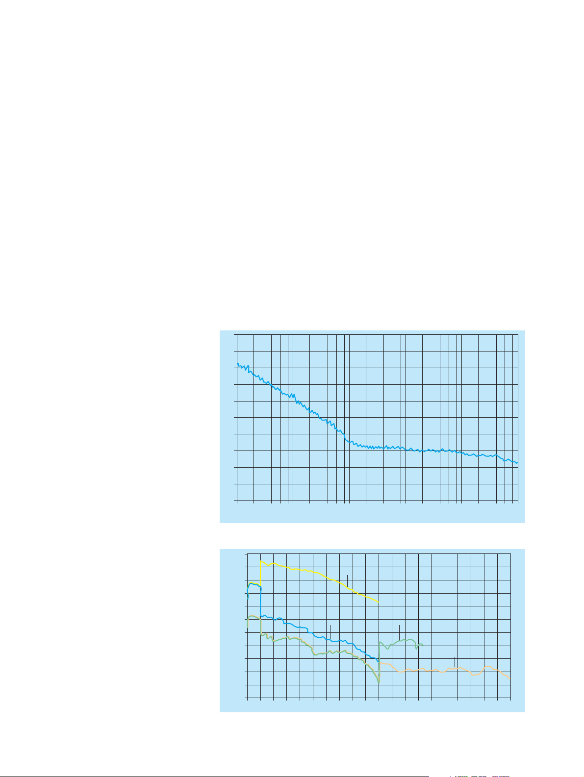
FIG 1: SSB phase noise at 10 GHz
30 dBm
28 dBm
26 dBm
24 dBm
22 dBm
20 dBm
18 dBm
16 dBm
14 dBm
12 dBm
10 dBm
FIG 2: Typical maximum level versus frequency
2468 2468 2468 2468 2468
10 Hz 100 Hz 1 kHz 10 kHz 100 kHz 1 MHz
SMP 22
SMP 02
8 dBm
0.01 2 4 6 8 10 12 14 16 18 20 22 24 26 28 30 32 34 36 38
SMP 03
SMP 04
Microwave Signal Generator SMP 3
40 GHz
Page 4
The SMP is setting standards with a resolution of 0.1 Hz throughout its frequency
range, and even above 20 GHz.
Variety of applications
The SMP is ideal for the following applications:
◆ Substitution of local oscillators
◆ Measurements on nonlinear compo-
nents such as frequency multipliers or
high-level mixers
◆ Driving of TWTs and other power
stages
◆ Interconnection of several signal gen-
erators for intermodulation measurements
◆ Tracking generator for spectrum and
network analyzers
High-quality shielding
Sensitivity measurements on low-noise
satellite receivers can only be made with
absolutely RF-leakage-proof signal
sources.
The comprehensive shielding of the SMP
ensures extremely low RF leakage.
Frequency and phase modulation
The SMP is fitted as standard with a
broadband FM modulator covering a
modulation frequency range up to 5 MHz
for deviations up to 10 MHz (20 MHz
above 20 GHz).
In addition, a precision FM/
tor (option SM-B5) with a modulation frequency range of up to 1 MHz and maximum deviation of up to 1 MHz (2 MHz for
f >20 GHz) is available for testing communication receivers and for scientific applications.
ϕM modula-
FSK modulation
Thanks to a special frequency control circuit, the precision FM/
ϕM modulator fea-
tures an extremely high carrier frequency
accuracy and stability in the FM DC
mode. Digital frequency shift keying (FSK
modulation) is also possible. A deviation
of up to 1 MHz (2 MHz above 20 GHz) can
be selected.
Wide
ϕM modulation range
The wide frequency range of the phase
modulation extending from DC to 100 kHz
allows testing of phase-sensitive circuits.
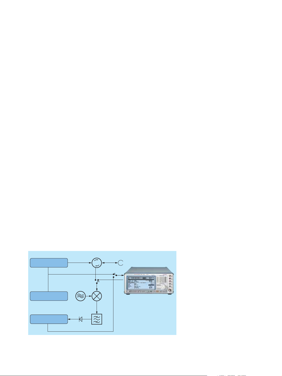
SMP for use as a VCO
In DC-coupled FM or
ϕM mode, the SMP
can also be used as a voltage-controlled
oscillator (VCO) and integrated into an
external frequency control loop. The RF
control output fitted on the rear panel is
very useful for this application.
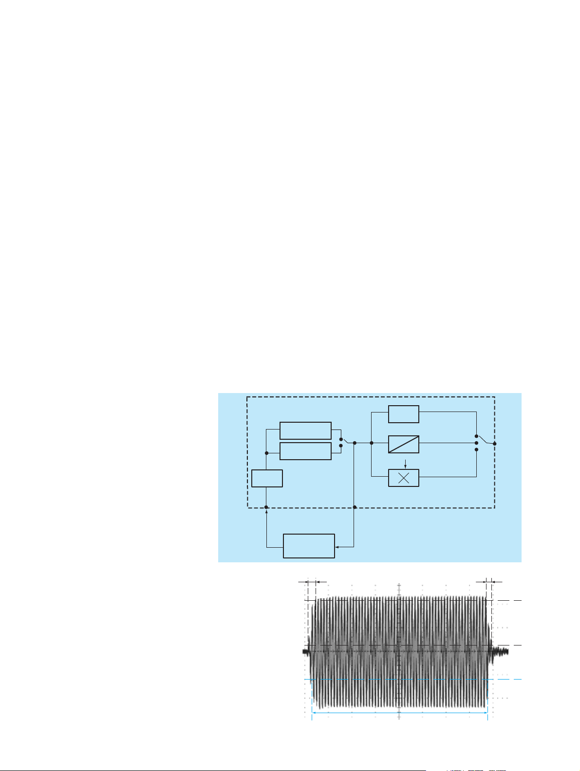
SMP
YIG
2 GHz to 10 GHz
YIG
10 GHz to 20 GHz
FM/ϕM
FMDC non-synchronized
modulator
(unlocked)
EXT1 or EXT2
DUT
Frequency divider/
phase comparator/
control amplifier
FIG 3: SMP as VCO
FIG 4: Pulse modulator,
universally used in
microwave applications
such as radar;
(1) shortest pulse duration 20 ns,
(2) 3 ns typ. rise/fall
time, more than 80 dB
on/off ratio
(2) (2)
The RF control output provides signals in
the frequency range 2 GHz to 20 GHz and
can for example be used for monitoring
the output frequency with the aid of a
frequency counter (FIG 3).
Pulse modulation
Ideal for radar receivers
All data specified for pulse modulation,
which is frequently used in the development, production and maintenance of
radar receivers is valid throughout the
rated frequency range and also at the
important intermediate frequencies of
70 MHz and 140 MHz. The on/off ratio is
better than 80 dB, the rise/fall time
shorter than 10 ns. Pulse widths of less
than 20 ns are possible (FIG 4).
Optional pulse generator
In addition to feeding in external modulation signals, the pulse generator (option
SMP-B14) can also be used to generate
direct
2 GHz to 20 GHz
SMP 03/SMP 04
1
2
20 GHz to 40 GHz
6 GHz
SMP-B11
2 GHz to 20 GHz
(RF control output)
10 MHz to 2 GHz
(1)
RF
out
90 %
10 %
50 %
4 Microwave Signal Generator SMP
Page 5
internal single or double pulses with
pulse frequencies up to 10 MHz.
The pulse generator can also be triggered
externally, pulse width and delay being
user-selectable over a wide range.
Simultaneous modulation modes
and their application
All modulation modes which the SMP is
able to generate can be combined (in the
case of SMP03/04 with some restrictions
regarding pulse and amplitude modulation). Highly complex signals can thus be
generated for modern communication
and radar systems.
Doppler effects
The combination of pulse modulation and
FM DC simulates Doppler effects and also
chirp signals.
Pulse radar with rotating antenna
Combined scan and pulse modulation
provides the type of signals occurring in
pulse radar applications with rotating
antenna.
In the example shown in Fig. 5, the external pulse from the pulse generator or
radar display is applied to the external
pulse input of the SMP and used as a trig-
ger for the internal pulse generator and
modulator.
The main advantage of this kind of trigger
is that it can be delayed to simulate distance and direction and to check the values on the display.
Fading
Simultaneous frequency and amplitude
modulation can be used to study fading
effects of FM receivers.
Sweep capabilities
Level sweep
The 20 dB level sweep of the SMP is an
efficient function for determining power
characteristics and for compression
measurements.
Digital frequency sweep
The digital frequency sweep with steps
from 10 ms is a useful facility for measuring the frequency response of microwave
modules or antennas.
Sweep modes
The digital sweep can be executed automatically in repetitive mode or in singleshot mode with selectable sweep time.
Manual sweeping (STEP MODE) within
the sweep limits is also possible. Trigger
inputs and outputs facilitate synchronous
operation in conjunction with other
instruments.
Use in EMC measurements
Functions qualifying the SMP for EMC
applications include the trigger facility for
step-by-step sweeping, marker outputs
and, above all, the extension of the frequency range to 10 MHz (option SMP-B11).
The capability of compensating external
frequency responses is also an important
feature.
Frequency hopping in list mode
One of the very special features of the
SMP is the list mode. Unlike the normal
sweep mode with increasing or decreasing frequencies, the list mode can be
used for programming frequency hopping. A list editor makes programming
extremely easy. Up to 2003 pairs of frequency and level values can be stored in
lists.
Of course, the same types of sweep can
be executed in the list mode as in the normal sweep mode.
Frequency response
compensation
Circulator
Pulsed Transmitter
Pulse
1
LO RF
Pulse Generator
2
Sideband
Filter
Display
Antenna direction pulse
FIG 5: Radar tests (switch position 1 for testing the distance indicated by radar,
switch position 2 for testing the antenna direction indicated by radar)
Power amplifiers, cables, antennas and
TEM cells usually exhibit a relatively large
frequency response which has to be compensated to obtain accurate measurement results.
The SMP provides two excellent tools for
the correction of external frequency
responses:
◆ User-defined correction of external
frequency responses
◆ External level control using a power
meter
Microwave Signal Generator SMP 5
Page 6

User-defined correction of external
frequency responses
The user correction function is extremely
useful for fast RF sweeps, for example to
compensate nonlinearities of an amplifier.
Power Amplifier DUTHorn Antenna
The known frequency response can be
compensated by entering level correction
values for up to 160 frequency points. The
correction values for the frequencies
between these points are determined by
means of automatic interpolation (FIG 6).
External level control using a power
meter
A very simple method is the external level
control with high level accuracy.
In this configuration, the SMP measures
automatically the level correction values
at a keystroke with the aid of an external
Power Meter NRVS or NRVD from
Rohde &Schwarz (FIG 7).
5
5
5
3
3
5
5
5
FIG 6: Output level with frequency response correction ON (yellow curve) and OFF (orange curve)
V/GHz
EXT ALC
Signal Generator SMP
RF
DUT
Power splitter
DC FREQ
DC
Power Meter NRVS
Power Sensor
NRV-Z15
Scalar network analysis
The Signal Generator SMP used as a
tracking generator in conjunction with
the Spectrum Analyzer FSP and the
option FSP-B10 provides a unique scalar
network analysis function. This application features an extremely wide dynamic
range, which allows, for example, filter
resonances in the stop band to be displayed at very low levels.
Due to the user-definable frequency offset, measurements on frequency-converting devices can also be performed with
this configuration.
FIG 7: External level control for Signal Generator SMP
FSP + FSP-B10
Aux
Aux
DUT
Trigger
GPIB
REF 10 MHz
FIG 8: Scalar network analysis with Signal Generator SMP and Spectrum Analyzer FSP with
option FSP-B10
Blanking signal
Blank
Trigger
SMP
6 Microwave Signal Generator SMP
Page 7

The FM modulation menu shows the clear-cut representation of selectable parameters and current
instrument status. Each setting can be made quickly and easily by means of the spinwheel and a few
keys.
Menu memories
Frequently used menu settings can be
stored in two memories and recalled at a
keystroke.
FIG 11: Storage of menu settings
Automatic measurement
functions for production and test
labs
The memory sequence is an extremely
useful function. It provides convenient
execution of standard test routines or frequently required sequences of different
types of single measurements.
Up to 50 complete instrument setups can
be stored. After programming the
sequence of measurements to be executed, the user can activate the autorun
control facility.
Remote control to SCPI standard
The IEEE-bus remote control commands
are in line with the SCPI guidelines. One
of the advantages is that the user can
exchange measuring instruments in an
automatic system without having to modify the control software.
Intelligent operating concept
Easy-to-follow menus
Neither multifunction keys nor obscure
special functions burden the user. All
functions are clearly arranged in menus.
Menus and functions as well as parameter settings can be conveniently selected
with a spinwheel.
Easy-to-read screen display
All settings associated with a certain
function can be seen at a glance on the
large-size, high-contrast LC display.
HELP function
Explanatory remarks can be called up for
each individual menu. This does away
with wasting time in looking up functions
in a manual.
FIG 12: Online help
FIG 9: SAVE and RCL for storing and recalling
settings
This function also allows synchronous
operation with other units through triggering. Step times can be separately programmed for each step.
FIG 10: General settings and menu selection
with spinwheel, RETURN, SELECT and arrow
keys
Microwave Signal Generator SMP 7
Page 8

Expertise in microwaves
Continuity of progress at
Rohde&Schwarz
The name of Rohde& Schwarz is also synonymous with quality in the field of
microelectronics.
Large investments have been made in
advanced technologies to fully keep up
with the ever increasing demands made
on the precision and reliability of microwave modules. Rohde &Schwarz uses
ultra-modern clean rooms and systems for
the development and production of thinfilm circuits.
Airbridges is an ideal technique for implementing PCB crossovers with excellent highfrequency characteristics. The above photo
has been taken with a scanning electron
microscope and shows such an airbridge
which is only 0.05 mm long.
8 Microwave Signal Generator SMP
Page 9

Specifications
SSB phase noise, 1 Hz bandwidth, FM off3)
Frequency
Range (standard)
SMP02/SMP22
SMP03
SMP04
Range (with option SMP-B11)
SMP02/SMP22
SMP03
SMP04
Resolution 0.1 Hz
Setting time (to within <1x10⁻⁶) after
IEC-/IEEE-bus delimiter
Phase offset adjustable in 1° steps
Reference frequency standard option SMP-B1
Aging (after 30 days of operation) 1 x 10⁻⁶/year <1 x 10⁻⁷/year
Temperature effect (0 °C to 55°C) 2 x 10
Warmup time – 10 min
Output for internal reference
Frequency
(EMF, sinewave)
Level V
rms
Source impedance
Input for internal reference
Frequency
Permissible frequency drift
Input level (V
Input impedance
Spectral purity
)
rms
2)
2 GHz to 20 GHz
2 GHz to 27 GHz
2 GHz to 40 GHz
10 MHz to 20 GHz
10 MHz to 27 GHz
10 MHz to 40 GHz
<(11 ms + 5 ms/GHz)
–6
1)
<1·10
10 MHz
1 V
50 Ω
1 MHz to 16 MHz in 1 MHz steps
–6
3 x 10
0.1 V to 2 V
200 Ω
–10
/°C
Offset from carrier
Frequency range 100 Hz 1 kHz 10 kHz 100 kHz
3)
10 MHz to <2 GHz
<–64 dBc <–93 dBc <–104 dBc <–104 dBc
2 GHz to 10 GHz <–64 dBc <–93 dBc <–105 dBc <–105 dBc
>10 GHz to 20 GHz <–58 dBc <–87 dBc <–99 dBc <–99 dBc
>20 to 27/40 GHz <–54 dBc <–81 dBc <–93 dBc <–93 dBc
Residual FM, rms, FM off
4)
Weighting bandwidth
Frequency range 300 Hz to 3 kHz 30 Hz to 20 kHz
3)
10 MHz to <2 GHz
<5 Hz <50 Hz
2 GHz to 10 GHz <5 Hz <50 Hz
>10 GHz to 20 GHz <10 Hz <75 Hz
>20 GHz to 27/40 GHz <20 Hz <150 Hz
Residual AM, rms, AM off
4)
Weighting bandwidth
Frequency range 300 Hz to 3 kHz 30 Hz to 20 kHz
10 MHz to <2 GHz <0.1% <0.2%
2 GHz to 20/27/40 GHz <0.05% <0.1%
Spurious
signals SMP02 SMP22 SMP03 SMP04
f <1.8 GHz
f ≥1.8 GHz
2)
2)
<–30 dBc
(<+8 dBm)
<–40 dBc
(<+10 dBm)
<–25 dBc
(<+8 dBm)
<–25 dBc
(<+15 dBm)
<–30 dBc
(<+3 dBm)
<–40 dBc
(<+3 dBm)
<–30 dBc
(<+0 dBm)
<–40 dBc
(<+0 dBm)
Harmonics
Harmonics
(with options
SMP-B12/
-B13, pulse
modulation
on)
f <1.8 GHz
f ≥1.8 GHz
<–25 dBc
(<+8 dBm)
<–25 dBc
(<+11 dBm)
<–25 dBc
(<+8 dBm)
<–25 dBc
(<+11 dBm)
<–25 dBc
(<+3 dBm)
<–25 dBc
(<+3 dBm)
<–25 dBc
(<+0 dBm)
<–25 dBc
(<+0 dBm)
Subharmonics
f ≤20 GHz
f >20 GHz––
–
–
–
<–40 dBc–<–30 dBc
Nonharmonics
at >10 kHz
from carrier
f <2 GHz
2 to 20 GHz
f >20 GHz
<–60 dBc typ.
<–60 dBc
–
<–60 dBc typ.
<–60 dBc
–
<–60 dBc typ.
<–60 dBc
<–54 dBc
<–60 dBc typ.
<–60 dBc
<–54 dBc
Level
Maximum level4) SMP02/SMP22 (without options SMP-B12/-B13)
SMP02 SMP22
Frequency range standard with option
SMP-B15
10MHz to <2GHz >+17 dBm
2 GHz to 20 GHz >+11.5 dBm >+10 dBm >+20 dBm
Maximum level4) SMP02/SMP22 (with options SMP-B12/-B13)
SMP02 SMP 22
Frequency range Pulse modu-
lation off
Pulse modulation on
10MHz to <2GHz >+13 dBm
2 GHz to 20 GHz like max. level
>+13 dBm like max. level
without
options
SMP-B12/
-B13
standard with option
SMP-B15
>+18.5 dBm
Pulse modulation off
Pulse modulation on
>+13 dBm
without
options
SMP-B12/
-B13
Microwave Signal Generator SMP 9
Page 10

Maximum level4) SMP03/SMP04 (without options SMP-B12/-B13)
SMP03 SMP04
Frequency range standard with option
SMP-B15
standard with option
SMP-B17
10 MHz to <2 GHz >+12 dBm
2 GHz to <18 GHz >+10 dBm >+8.5 dBm >+10 dBm >+8.5 dBm
18 GHz to 20 GHz >+6 dBm >+4.5 dBm >+6 dBm >+4.5 dBm
>20 to 27/33 GHz >+13 dBm >+11 dBm >+12 dBm >+10 dBm
>33 GHz to 40 GHz – – >+10 dBm >+8 dBm
Maximum level4) SMP03/SMP04 (with options SMP-B12/-B13)
SMP03 SMP04
Frequency range Pulse modu-
lation off
Pulse modulation on
Pulse modulation off
Pulse modulation on
10 MHz to <2 GHz >+10 dBm
2 to 20/27/40 GHz like max. level without options SMP-B12/-B13
Minimum level of all models
without option SMP-B15/-B17
with option SMP-B15/-B17
–20 dBm
–130 dBm
Resolution 0.1 dB or 0.01 dB
Tota l acc urac y
3)5)
(frequency response and temperature effect included)
Frequency range Level Accuracy
10 MHz to <2 GHz >+10 dBm
>–10 dBm
>–60 dBm
≤–60 dBm
2 GHz to 20 GHz >+10 dBm
>–10 dBm
>–60 dBm
≤–60 dBm
>20 GHz to 27/40 GHz >+10 dBm
>–10 dBm
>–60 dBm
≤–60 dBm
<±1.2 dB
<±0.6 dB
<±0.9 dB
<±1.4 dB
<±1.3 dB
<±0.7 dB
<±1.0 dB
<±1.5 dB
<±1.5 dB
<±0.9 dB
<±1.2 dB
<±1.7 dB
Output impedance 50 Ω
VSWR
f ≤20 GHz
f >20 GHz
<2, <1.6 typ.
<2.2, <1.8 typ.
Setting time
(after IEC/IEEE-bus delimiter)
<10 ms
with option SMP-B15/-B17, with
switching in attenuator set
<25 ms
Non-interrupting level setting
(ATTENUATOR MODE FIXED)
Setting range
Simultaneous modulation
0 dB to 20 dB
any combination of AM (scan modula-
tion), FM (ϕM) and pulse modulation
Linear amplitude modulation
Operating modes internal, external AC/DC
Modulation depth
6)
0% to 90%
Resolution 0.1%
Setting accuracy at AF = 1 kHz
7)
(m <80%)
AM distortion at AF = 1 kHz
(m = 60%)
7)
, f >50 MHz <1%, <0.5 % typ.
<(4% of reading ±1%)
Modulation frequency range for frequency response <1 dB, m = 60%
f <2 GHz
f ≥2 GHz
DC to 100 kHz
DC to 10 kHz
DC to 50 kHz
Modulation input EXT1
Input impedance
600 Ω or 100 kΩ
Input voltage (peak value) for
selected modulation depth
1 V (HIGH/LOW warning if
variation >3 %)
Logarithmic amplitude modulation (scan modulation)
Operating modes internal, external
Dynamic range >30 dB
Sensitivity 0.1 dB/V to 10 dB/V
Resolution 0.01 dB/V
Rise/fall time (10%/90 %) <10 µs
Modulation input EXT1
Input impedance
Input voltage
600 Ω or 100 kΩ
–6 V to +6 V
Frequency modulation
Operating modes internal, external AC/DC, locked/
Standard FM (without option SM-B5)
Maximum deviation
f ≤20 GHz
f >20 GHz
Resolution
f ≤20 GHz
f >20 GHz
Setting accuracy at AF = 100 kHz
and 500 kHz deviation
FM distortion at AF = 50 kHz
and 500 kHz deviation
Modulation frequency range
Locked mode
Unlocked mode
Modulation frequency response
Locked mode, modulation index
<10, deviation = 100 kHz
10 kHz to 5 MHz
Unlocked mode, deviation = 10 MHz
10 Hz (DC) to 100 kHz
100 kHz to 5 MHz
Incidental AF = 50 kHz and
100 kHz deviation
Carrier frequency offset with FM
Locked mode
Unlocked mode
f ≤20 GHz
f >20 GHz
unlocked, two-tone with two separate
channels FM1 and FM2
10 MHz
20 MHz
<1%, min. 10 Hz
<1%, min. 20 Hz
<10% of reading
<0.5%, 0.05% typ.
10 kHz to 5 MHz
DC to 5 MHz
<5 dB
<1 dB
<5 dB
<0.5%
–
<10 MHz typ.
<20 MHz typ.
10 Microwave Signal Generator SMP
Page 11

FM (with option SM-B58))
Maximum deviation
f ≤20 GHz
f >20 GHz
1 MHz
2 MHz
Resolution
f ≤20 GHz
f >20 GHz
<1%, min. 10 Hz
<1%, min. 20 Hz
Setting accuracy at AF = 1 kHz and
deviation >1 kHz
<2% of reading
FM distortion at AF = 1 kHz and
500 kHz deviation
Modulation frequency range
<0.5%, 0.05% typ.
DC to 1 MHz
Modulation frequency response
10 Hz (DC) to 50 kHz
50 kHz to 1 MHz
<0.5 dB
<4 dB
Incidental AF = 1 kHz and
40 kHz deviation
<0.5%
Carrier frequency offset with FM
f ≤20 GHz
f >20 GHz
Carrier frequency drift with FMDC
<100 Hz + 1% of deviation
<200 Hz + 1% of deviation
0.005% typ. of deviation per 1°C
Modulation inputs EXT1, EXT2
Input impedance
600 Ω or 100 kΩ
Input voltage (peak value)
for selected deviation
1 V (HIGH/LOW warning if
variation >3 %)
Phase modulation with option SM-B5
Operating modes internal, external AC/DC, two-tone
Maximum deviation
f ≤20 GHz
f >20 GHz
Resolution
f ≤20 GHz
f >20 GHz
Setting accuracy at AF = 1 kHz
f ≤20 GHz
f >20 GHz
ϕM distortion at AF = 1 kHz and
5 rad deviation
Modulation frequency range DC to 100 kHz
Modulation frequency response
10 Hz (DC) to 100 kHz
Modulation input EXT1, EXT2
Input impedance
Input voltage (peak value)
for selected deviation
with two separate channels ϕM1 and
ϕM2
10 rad
20 rad
<1%, min. 0.001 rad
<1%, min. 0.002 rad
<(3% of reading + 0.01 rad)
<(3% of reading + 0.02 rad)
<1%
<3 dB
600 Ω or 100 kΩ
1 V (HIGH/LOW warning if
variation >3 %)
ASK modulation
Operating mode external
Maximum modulation depth
Resolution 0.1%
7)
Data rate
Rise/fall time (10%/90 %) <10 µs
Modulation input EXT1
Input impedance
Input level
6)
90%
0 Hz to 200 kHz
600 Ω or 100 kΩ
TTL/HCT signal, selectable polarity
FSK modulation
Operating mode external
Maximum shift
Standard FM
f ≤20 GHz
f >20 GHz
10 MHz
20 MHz
with option SM-B5
f ≤20 GHz
f >20 GHz
1 MHz
2 MHz
Resolution
f ≤20 GHz
f >20 GHz
<1%, min. 10 Hz
<1%, min. 20 Hz
Data rate
Standard FM
Locked mode
Unlocked mode
with option SM-B5
20 kHz to 2 MHz
0 Hz to 2 MHz
0 Hz to 2 MHz
Modulation input EXT1
Input impedance
Input level
600 Ω or 100 kΩ
TTL/HCT signal, selectable polarity
Pulse modulation
Operating modes external, internal with option SMP-B14
Standard
(without options SMP-B12/-B13)
Frequency range
On/off ratio
Rise/fall time (10%/90 %)
Minimum pulse width
Maximum pulse pause
with level control switched on
(ALC ON)
with level control switched off
(ALC OFF)
Minimum pulse/pause ratio
with level control switched on
(ALC ON)
with level control switched off
(ALC OFF)
Pulse repetition frequency
Pulse delay
Video feedthrough
With options SMP-B12/-B13
Frequency range
With option SMP-B13
With option SMP-B12
On/off ratio
Rise/fall time (10%/90 %)
Minimum pulse width
with level control switched on
(ALC ON)
with level control switched off
(ALC OFF)
Maximum pulse pause
with level control switched on
(ALC ON)
with level control switched off
(ALC OFF)
Minimum pulse/pause ratio
with level control switched on
(ALC ON)
with level control switched off
(ALC OFF)
Pulse repetition frequency
Pulse delay
Video feedthrough
PULSE modulation input
Input level
Input impedance
≥2 GHz
>50 dB (level >0 dBm)
<500 ns
1 µs
any (SMP02/22)/40 ms (SMP 03/04)
any
any (SMP02/22)/1:100 (SMP 03/04)
any
0 Hz to 500 kHz
100 ns typ.
<15 mV (peak value)
10 MHz to <2 GHz
≥2 GHz
>80 dB
<10 ns
20 ns (SMP02/22)/1 µs (SMP 03/04)
20 ns
any (SMP02/22)/40 ms (SMP 03/04)
any
any (SMP02/22)/1:100 (SMP 03/04)
any
0 Hz to 10 MHz
50 ns typ.
<15 mV (peak value)
TTL (HCT)
50 Ω or 10 kΩ
Microwave Signal Generator SMP 11
Page 12

Internal modulation generator
Frequency 0.4/1/3/15 kHz ± 3 %
Open-circuit voltage at LF connector 1 V ± 1% (R
(peak value)
= 10 Ω, R
out
>200 Ω)
load
LF generator option SM-B2
Waveform s sinewave, triangular, squarewave,
Frequency range
Sinewave, noise
Triangular, squarewave
Resolution 0.1 Hz
Frequency accuracy <1 x 10
Frequency response (sinewave)
up to 100 kHz
up to 500 kHz
Distortion (20 Hz to 100 kHz) <0.1% (for level >0.5 V)
Open-circuit voltage at LF connector
Resolution
Setting accuracy at 1 kHz
Frequency setting time
(after IEC/IEEE-bus delimiter)
noise
0.1 Hz to 500 kHz
0.1 Hz to 50 kHz
–4
<0.3 dB
<0.5 dB
1 mV to 4 V (R
1 mV
out
±1% + 1 mV
<10 ms
= 10 Ω, R
>200 Ω)
load
Pulse generator option SMP-B14
Operating modes single pulse, delayed pulse, double
Active trigger edge positive or negative
Pulse repetition period
Resolution
Accuracy
Pulse width
Resolution
Accuracy
Pulse delay
Resolution
Accuracy
Double pulse
Resolution
Accuracy
Trigger delay <50 ns
PULSE modulation input
Input level
Input impedance
SYNC output TTL level (HC), 40 ns pulse width
VIDEO output TTL level (HC)
pulse
100 ns to 85 s
5 digits, min. 20 ns
same as reference frequency
40 ns to 1 s
4 digits, min. 20 ns
<(5% of reading ± 3 ns)
40 ns to 1 s
4 digits, min. 20 ns
±5% of reading
–10 ns to +20 ns
60 ns to 1 s
4 digits, min. 20 ns
±5% of reading
–10 ns to +20 ns
TTL (HCT)
50 Ω or 10 kΩ
SYNC output
PP
PD PW
RF control output
Frequency range 2 GHz to 20 GHz
Level approx. 0 dBm
Sweep
digital sweep in discrete steps
RF sweep, AF sweep
Operating modes
AF sweep with option SM-B2
automatic, single-shot, manual or externally triggered, linear or logarithmic
Sweep range
Step width linear
Step width logarithmic
user-selectable
0.01% to 50 %
Level sweep
Operating modes
automatic, single-shot, manual or
externally triggered, logarithmic
Sweep range
Step width
Step time
Resolution
0.1 dB to 20 dB
0.1 dB to 20 dB
10 ms to 1 s
0.1 ms
Markers 3, user-selectable
MARKER output TTL/HC logic signal, selectable polarity
X output 0 V to 10 V
BLANK output TTL/HC logic signal, selectable polarity
TRIGGER input TTL/HCT logic signal, polarity of active
trigger edge selectable
STOP input TTL/HCT logic signal, selectable
polarity
LIST mode
frequency and level values can be
stored and read out fast; permissible
level variation range: 20 dB
Operating modes automatic, single-shot, manual or
externally triggered
Max. length of list 2003 pairs of frequency and level
values
Step time
(1 ms to 1 s) + the less of 5 ms/GHz or
50 ms
Resolution
0.1 ms
Memory for instrument settings
Storable settings 50
Memory sequence modes
Operating modes
automatic, single-shot, manual or
externally triggered
Step time
Resolution
50 ms to 60 s
1 ms
Auxiliary interface with option SMP-B18
V/GHz output output voltage proportional to frequen-
cy, 0.5 V/GHz
Z output user-selectable level range
–10 V to +10 V
9)
or 1 V/GHz selectable
VIDEO output
RF output
The pulse generator option enables the pulse delay PD, pulse width PW and
pulse repetition period PP to be set with high accuracy and resolution.
Microwave Signal Generator SMP 12
Page 13

Remote control
System IEC625 (IEEE 488)
Command set SCPI 1992.0
Connector 24-contact Amphenol
IEC/IEEE-bus address 0 to 30
Interface functions SH1, AH1, T6, L4, SR1, RL1, PP1, DC1,
DT1, C0
General data
Power supply 90 V to 132 V (AC), 47 Hz to 440 Hz
180 V to 265 V (AC), 47 Hz to 440 Hz
autoranging, max. 400 VA
safety class I to VDE 0411 (IEC 348)
Electromagnetic compatibility
Standards adhered to postal regulation 243/1991
EN55011 (VDE 0875 T11), class B
VDE 0875, suppression level K
MIL-STD-461B
- RE02 radiated emissions
- CE03 conducted emissions
- CS01/02 conducted susceptibility
RF leakage (f <1 GHz) <0.1 µV (induced in a two-turn coil
2.5 cm in diameter held 2.5 cm away
from the surface of the case)
Radiated susceptibility 3 V/m
Ambient conditions
Rated temperature range 0°C to 55°C
10)
Storage temperature range –40°C to +70°C
Humidity DIN IEC 68-2-30, +40°C
Mechanical stress
Shock to MIL-STD-810D, 40 g shock spectrum
Vibration
sinusoidal
random
to DIN IEC 68-2-6, 5 Hz to 55 Hz
2
rms, 10 Hz to 300 Hz
10 m/s
Dimensions (W x H x D) 435 mm x 192 mm x 570 mm
Weig ht 27 kg, when fully equipped
1)
For frequency changes beyond the 2 GHz and 20 GHz frequency limit the setting time is
max. 50 ms longer.
2)
Specifications for harmonics above 20 GHz (SMP 02/SMP 22), 27 GHz (SMP 03) and 40 GHz
(SMP 04) only typical.
3)
Without optional Attenuator SMP-B15/-B17 specifications apply to levels >–5 dBm only.
4)
The maximum level is reduced by up to 2 dB in the temperature range 35°C to 55 °C.
5)
The specified accuracy only applies to temperatures from 15°C to 35 °C. Outside this range the
accuracy may be degraded by max. 0.7 dB.
6)
The modulation depth adjustable within the AM specifications continuously decreases from
6 dB below the maximum level up to the maximum level.
7)
This specification does not apply to
a) non-interrupting level setting (ATTENUATOR MODE FIXED) if option SMP-B15/-B17 is used,
b) levels below –5 dBm without option SMP-B15/-B17,
c) external level control mode (EXT ALC).
8)
The functions of the standard FM remain available.
9)
Above 20 GHz (SMP 03/SMP 04) only 0.5 V/GHz available.
10)
The cont rast of th e LC d ispl ay is degr aded at hi gh tem pera ture s.
Certified Environmental System
ISO 14001
REG. NO 1954
Certified Quality System
ISO 9001
DQS REG. NO 1954
Microwave Signal Generator SMP 13
Page 14

Ordering information
Order designation Typ e Order No.
Signal Generator SMP02 1035.5005.02
Signal Generator SMP22 1035.5005.22
Signal Generator SMP03 1035.5005.03
Signal Generator SMP04 1035.5005.04
Accessories supplied power cable, operating manual
for SMP02/22/03
for SMP 04
female adapter 3.5 mm
female adapter 2.9 mm
Options
Frequency Extension
0.01 GHz to 2 GHz
1)
SMP-B11 1036.6240.02
Pulse Modulator
2 GHz to 20 GHz
(SMP02, SMP22)
2 GHz to 27 GHz
(SMP03)
2 GHz to 40 GHz
(SMP04)
0.01 GHz to 2 GHz
1)
SMP-B12
1)
1)
SMP-B12
SMP-B12
1)
SMP-B13
1036.5750.02
1036.5750.03
1036.5750.04
1036.7147.02
Pulse Generator SMP-B14 1036.7347.02
RF Attenuator
27 GHz (SMP02,
SMP22, SMP 03)
40 GHz (SMP04)
1)
SMP-B15
1)
SMP-B17
1036.5250.02
1036.5550.02
Order designation Typ e Order No.
Extras
Service Kit SM-Z2 1039.3520.02
Trolley ZZK-1 1014.0510.00
Transit Case ZZK-945 1013.9372.00
Adapter (SMP02,
SMP22, SMP03)
3.5 mm, female
3.5 mm, male
N, female
N, male
1021.0512.00
1021.0529.00
1021.0535.00
1021.0541.00
Adapter (SMP04)
2.9 mm, female
2.9 mm, male
N, female
N, male
1)
Factory-fitted option.
1036.4790.00
1036.4802.00
1036.4777.00
1036.4783.00
Printed in Germany 0202 (Bi ko)
Auxiliary Interface SMP-B18 1036.8920.02
Rear Connectors for
RF, AF
SMP02, SMP 22,
SMP03
SMP04
1)
1)
SMP-B19
SMP-B20
1039.4303.02
1039.4503.02
OCXO Reference
Oscillator
SMP-B1 1036.5109.02
LF Generator SM-B2 1036.7947.02
FM/ϕM Modulator SM-B5 1036.8489.02
19" Rack Adapter ZZA-94 0396.4905.00
Data without tolerances: typical values
⋅
Subject to change
⋅
Trade names are trademarks of the owners
⋅
Microwave Signal Generator SMP
⋅
ROHDE& SCHWARZ GmbH & Co. KG ⋅ Mühldorfstraße 15 ⋅ 81671 München ⋅ Germany ⋅ P.O.B. 8014 69 ⋅ 81614 München ⋅ Germany ⋅ Telephone +49 89 41 29-0
www.rohde-schwarz.com ⋅ Customer Support: Tel. +49 180512 4242, Fax +49 89 4129-137 77, E-mail: CustomerSupport@rohde-schwarz.com
PD 0757.0935.23
 Loading...