

Page 1

Technical Specifications
Discontinued Product Information
— For Support Reference Only —
Information herein, may refer to products/services no longer supported.
We regret any inconvenience caused by obsolete information. For the
latest information on Agilent’s test and measurement products go to:
www.agilent.com/find/products
In the US, call Agilent Technologies at 1-800-829-4444
(any weekday between 8am–5pm in any U.S. time zone)
World-wide Agilent sales office contact information is available at:
www.agilent.com/find/contactus
Agilent Technologies
PNA Series Network Analyzers
E8801A, E8802A, and E8803A
Page 2

Documentation Warranty
THE MATERIAL CONTAINED IN THIS DOCUMENT IS PROVIDED "AS IS," AND IS
SUBJECT TO BEING CHANGED, WITHOUT NOTICE, IN FUTURE EDITIONS. FURTHER, TO THE MAXIMUM EXTENT PERMITTED BY APPLICABLE LAW, AGILENT
DISCLAIMS ALL WARRANTIES, EITHER EXPRESS OR IMPLIED WITH REGARD TO
THIS MANUAL AND ANY INFORMATION CONTAINED HEREIN, INCLUDING BUT
NOT LIMITED TO THE IMPLIED WARRANTIES OF MERCHANTABILITY AND FITNESS FOR A PARTICULAR PURPOSE. AGILENT SHALL NOT BE LIABLE FOR
ERRORS OR FOR INCIDENTAL OR CONSEQUENTIAL DAMAGES IN CONNECTION
WITH THE FURNISHING, USE, OR PERFORMANCE OF THIS DOCUMENT OR ANY
INFORMATION CONTAINED HEREIN. SHOULD AGILENT AND THE USER HAVE A
SEPARATE WRITTEN AGREEMENT WITH WARRANTY TERMS COVERING THE
MATERIAL IN THIS DOCUMENT THAT CONFLICT WITH THESE TERMS, THE WARRANTY TERMS IN THE SEPARATE AGREEMENT WILL CONTROL.
DFARS/Restricted Rights Notice
If software is for use in the performance of a U.S. Government prime contract or
subcontract, Software is delivered and licensed as “Commercial computer software” as
defined in DFAR 252.227-7014 (June 1995), or as a “commercial item” as defined in FAR
2.101(a) or as “Restricted computer software” as defined in FAR 52.227-19 (June 1987) or
any equivalent agency regulation or contract clause. Use, duplication or disclosure of
Software is subject to Agilent Technologies’ standard commercial license terms, and
non-DOD Departments and Agencies of the U.S. Government will receive no greater than
Restricted Rights as defined in FAR 52.227-19(c)(1-2) (June 1987). U.S. Government users
will receive no greater than Limited Rights as defined in FAR 52.227-14 (June 1987) or
DFAR 252.227-7015 (b)(2) (November 1995), as applicable in any technical data.
ii
Page 3

Contacting Agilent
Online assistance: www.agilent.com/find/assist
Americas
Brazil
(tel) (+55) 11 4197 3600
(fax) (+55) 11 4197 3800
Australia
(tel) 1800 629 485
(alt) 1800 143 243
(fax) 1800 142 134
Japan
(tel) 0120 421 345
(alt) (+81) 426 56 7832
(fax) 0120 421 678
Taiwan
(tel) 0800 047 866
(alt) 00801 651 317
(fax) 0800 286 331
Austria
(tel) 0820 87 44 11*
(fax) 0820 87 44 22
Canada
(tel) 877 894 4414
(fax) (+1) 905 282-6495
Asia Pacific and Japan
China
(tel) 800 810 0189
(alt) (+86) 10800 650 00 21
(fax) 800 820 2816
Malaysia
(tel) 1800 888 848
(alt) 1800 828 848
(fax) 1800 801 664
Thailand
(tel) 1800 226 008
(alt) (+66) 2 268 1345
(fax) (+66) 2 661 37 14
Belgium
(tel) (+32) (0)2 404 9340
(alt) (+32) (0)2 404 9000
(fax) (+32) (0)2 404 9395
Mexico
(tel) (+52) 55 5081 9469
(alt) 01800 5064 800
(fax) (+52) 55 5081 9467
Hong Kong
(tel) 800 930 871
(alt) (+852) 3197 7889
(fax) (+852) 2 506 9233
Singapore
(tel) 1800 375 8100
(alt) (+65) 6 375 8100
(fax) (+65) 683 6 0252
Europe
Denmark
(tel) (+45) 7013 1515
(alt) (+45) 7013 7313
(fax) (+45) 701 3 1555
United States
(tel) 800 829 4444
(alt) (+1) 303 662 3998
(fax) 800 829 4433
India
(tel) 1600 11 2 92 9
(fax) 000800 650 1101
South Korea
(tel) 080 769 0800
(alt) (+82) 2 2004 5004
(fax) (+82) 2 2004 5115
Finland
(tel) (+358) 10 855 2100
(fax) (+358) 10 855 2923
France
(tel) 0825 010 700*
(alt) (+33) (0)1 6453 5623
(fax) 0825 010 701*
Italy
(tel) (+39) (0)2 9260 8484
(fax) (+39) (0)2 9544 1175
Spain
(tel) (+34) 91 631 3300
(alt) (+34) 91 631 3000
(fax) (+34) 91 631 3301
Switzerland (Italian)
(tel) 0800 80 5353 opt. 3*
(alt) (+39) (0)2 9260 8484
(fax) (+41) (0)22 567 5314
(tel) = primary telephone number; (alt) = alternate telephone nu mber; (fax) = FAX number; * = in country number
Germany
(tel) 01805 24 6333*
(alt) 01805 24 6330*
(fax) 01805 24 6336*
Luxemburg
(tel) (+32) (0)2 404 9340
(alt) (+32) (0)2 404 9000
(fax) (+32) (0)2 404 9395
Sweden
(tel) 0200 88 22 55*
(alt) (+46) (0)8 5064 8686
(fax) 020 120 2266*
United King dom
(tel) (+44) (0)7004 666666
(alt) (+44) (0)7004 123123
(fax) (+44) (0)7004 444555
Ireland
(tel) (+353) (0)1 890 924 204
(alt) (+353) (0)1 890 924 206
(fax)(+353) (0)1 890 924 024
Netherlands
(tel) (+31) (0)20 547 2111
(alt) (+31) (0)20 547 2000
(fax) (+31) (0)20 547 2190
Switzerland (French)
(tel) 0800 80 5353 opt. 2*
(alt) (+33) (0)1 6453 5623
(fax) (+41) (0)22 567 5313
Israel
(tel) (+972) 3 9288 500
(fax) (+972) 3 9288 501
Russia
(tel) (+7) 095 797 3963
(alt) (+7) 095 797 3900
(fax) (+7) 095 797 3901
Switzerland (German )
(tel) 0800 80 5353 opt. 1*
(alt) (+49) (0)7031 464 63 33
(fax) (+41) (0)1 272 7373
iii
Page 4

This page intentionally left blank.
iv
Page 5

Technical Specifications for the E8801A, E8802A, E8803A
Definitions....................................................................................................................................2
Corrected System Performance.................................................................................................3
Table 1. System Dynamic Range........................................................................................3
Corrected System Performance with Type-N Connectors..................................................4
Table 2. Corrected System Performance With 85032F Calibration Kit.........................4
Table 3. Corrected System Performance With 85092C ECal Module............................5
Corrected System Performance with 3.5 mm Connecto rs...................................................6
Table 4. Corrected System Performance With 85033E Calibration Kit........................6
Table 5. Corrected System Performance With 85093C ECal Module............................7
Table 6. Corrected System Performance With 85038A Calibration Kit........................8
Table 7. Uncorrected Instrument Performance................................................................9
Test Port Output Characteristics (Sourc e)...............................................................................9
Table 8. Test Port Output Frequency................................................................................9
Table 9. Test Port Output Power .....................................................................................10
Table 10. Test Port Output Signal Purity........................................................................11
Test Port and Receiver Input Characteristics........................................................................11
Table 11. Test Port and Receiver Input Levels...............................................................11
Table 12. Test Port Input (Trace Noise)..........................................................................13
Table 13. Test Port Input (Reference Level and Stability)............................................13
Table 14. Test Port Input (Dynamic Accuracy specification)........................................14
Table 15. Test Port Input (Group Delay)........................................................................15
General Information.................................................................................................................15
Table 16. System Bandwidths...........................................................................................15
Table 17. Front Panel Information..................................................................................16
Table 18. Rear Panel Information....................................................................................17
Table 19. Rear Panel Information (continued)...............................................................18
Table 20. Analyzer Environment and Dimensions.........................................................19
Measurement Throughput Summary.....................................................................................20
Table 21. Typical Cycle Time (ms)...................................................................................20
Table 22. Cycle Time vs. IF Bandwidth...........................................................................20
Table 23. Cycle Time vs. Number of Points ....................................................................21
Table 24. Data Transfer Time (ms)..................................................................................22
Table 25. Recall and Sweep Speed...................................................................................23
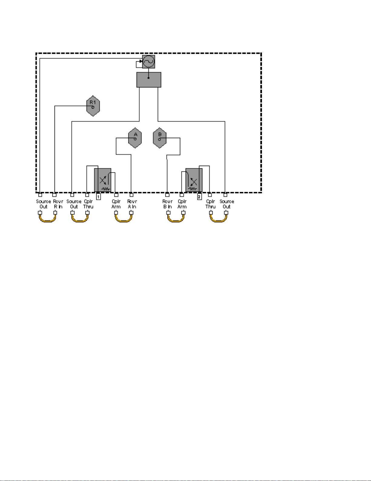
E8801A, E8802A, and E8803A Simplified Test Set Block Diagram...................................24
E8801A, E8802A, and E8803A with Option 014 Simplified Test Set Block Diagram.......25
1
Page 6

This is a complete list of the E8801A, E8802A, and E8803A network analyzer technical specifications.
• To optimize viewing of uncertainty curves, click the Maximize button.
• To view or print the PNA Series Data Sheet (a condensed version of the specifications), visit our web
site at http://www.agilent.com/find/pna, select your analyzer model, and click on the link for the data
sheet.
• The uncertainty curves contained in this document apply only to the setup conditions listed. Please
download our free Uncertainty Calculator from http://www.agilent.com/find/na_calculator
curves for your PNA setup. View the equations
used to generate the uncertainty curves.
to generate the
Definitions
All specifications and characteristics apply over a 25 °C ±5 °C range (unless otherwise stated) and 90 minutes
after the instrument has been turned on.
Specification (spec.): Warranted performance. Specifications include guardbands to account for the expected
statistical performance distribution, measurement uncertainties, and changes in performance due to
environmental conditions.
Characteristic (char.): A performance parameter that the product is expected to meet before it leaves the
factory, but that is not verified in the field and is not covered by the product warranty. A characteristic includes
the same guardbands as a specification.
Typical (typ.): Expected performance of an average unit which does not include guardbands. It is not covered
by the product warranty.
Nominal (nom.): A general, descriptive term that does not imply a level of performance. It is not covered by the
product warranty.
Calibration: The process of measuring known standards to characterize a network analyzer's systematic
(repeatable) errors.
Corrected (residual): Indicates performance after error correction (calibration). It is determined by the quality of
calibration standards and how well "known" they are, plus system repeatability, stability, and noise.
Uncorrected (raw): Indicates instrument performance without error correction. The uncorrected performance
affects the stability of a calibration.
Standard: When referring to the analyzer, this includes no options unless noted otherwise.
2
Page 7

Corrected System Performance
Note: This document provides technical specifications for the following calibration kits only: 85032F, 85092C,
85033E, 85093C and 85038A.
The specifications in this section apply for measurements made with the E8801A, E8802A, and E8803A
analyzer with the following conditions:
• 10 Hz IF bandwidth
• No averaging applied to data
• Environmental temperature of 25 °C ±5 °C, with < 1 °C deviation from calibration temperature
• Isolation calibration not omitted
Table 1. System Dynamic Range
Description Specification (dB) Characteristic (dB)
Dynamic rangea (at test port)
300 kHz to 25 MHz
25 MHz to 3 GHz
3 GHz to 6 GHz 118
6 GHz to 9 GHz 115
Dynamic rangec (at receiver input)
300 kHz to 25 MHz
25 MHz to 3 GHz
3 GHz to 6 GHz
6 GHz to 9 GHz
b
125
b
128
d
d
140
143
133
130
a
The test port dynamic range is calculated as the difference between the test port rms noise floor and the source maximum output power.
The effective dynamic range must take measurement uncertainties and interfering signals i nto acc ount.
b
May be limited to 100 dB at particular frequencies below 750 MHz due to spurious receiver residuals.
c
The receiver input dynamic range is calculated as the difference between the receiver rms noise floor and the source maximum output
power. The effective dynamic range must take measurement uncertainties and interfering si gnals i nto acc ount. This set-up should onl y be
used when the receiver input will never exceed its damage level. When the analyzer is in segment sweep mode, frequency segments can be
defined with a higher power level when the extended dynamic range is required (i.e. the portion of the device's response with high insertion
loss), and reduced power when receiver damage may occur (i.e. the portion of the devices's response with low insertion loss).
d
May be limited to 115 dB at particular frequencies below 750 MHz due to spurious receiver residuals.
Note: Receiver Dynamic Range specifications are not included in this E8801/2/3A document.
3
Page 8

Corrected System Performance with Type-N Connectors
Table 2. Corrected System Performance With Type-N Device Connectors, 85032F Calibration
Kit
Applies to the E8801A, E8802A, and E8803A analyzer, 85032F (Type-N, 50Ω) calibration kit, N6314A test port cable, and a full 2-port
calibration. Also applies to the following conditions:
• IF bandwidth = 10 Hz
• No averaging applied to data
• Environmental temperature 25° ±5 °C, with < 1 °C deviation from calibration temperature
• Isolation calibration not omitted
Specification (dB) Description
300 kHz to
1.3 GHz
Directivity 49 46 40 38
Source Match 41 40 36 35
Load Match 49 45 39 37
Reflection Tracking ±0.011 ±0.021 ±0.032 ±0.054
Transmission
Tracking
Transmission Uncertainty (Specifications)
±0.012 ±0.020 ±0.055 ±0.083
1.3 GHz to
3 GHz
3 GHz to
6 GHz
6GHz to
9 GHz
Reflection Uncertainty (Specifications)
4
Page 9

Table 3. Corrected System Performance With Type-N Device Connectors, 85092C Electronic
Calibration Module
Applies to the E8801A, E8802A, and E8803A analyzer, 85092C (Type-N, 50Ω) electronic calibration (ECal) module, N6314A test port cable,
and a full 2-port calibration. Also applies to the following conditions:
• IF bandwidth = 10 Hz
• No averaging applied to data
• Environmental temperature 25° ±5 °C, with < 1 °C deviation from calibration temperature
• Isolation calibration not omitted
Directivity 52 54 52 47
Source Match 45 44 41 36
Load Match 47 47 44 39
Reflection Tracking ±0.040 ±0.040 ±0.060 ±0.070
Transmission
Tracking
Transmission Uncertainty (Specifications)
Specification (dB) Description
300 kHz to
1.3 GHz
±0.039 ±0.039 ±0.068 ±0.136
1.3 GHz to
3 GHz
3 GHz to
6 GHz
6 to
9 GHz
a
Reflection Uncertainty (Specifications)
5
Page 10

Corrected System Performance with 3.5 mm Connectors
Table 4. Corrected System Performance With 3.5 mm Device Connector Type, 85033E
Calibration Kit
Applies to the E8801A, E8802A, and E8803A analyzer, 85033E (3.5 mm, 50Ω) calibration kit, N6314A test port cable, and a full 2-port
calibration. Also applies to the following conditions:
• IF bandwidth = 10 Hz
• No averaging applied to data
• Environmental temperature 25° ±5 °C, with < 1 °C deviation from calibration temperature
• Isolation calibration not omitted
Directivity 46 44 38 38
Source Match 43 40 37 36
Load Match 46 44 38 38
Reflection Tracking ±0.006 ±0.007 ±0.009 ±0.010
Transmission
Tracking
Transmission Uncertainty (Specifications)
Specification (dB) Description
300 kHz to
1.3 GHz
±0.012 ±0.021 ±0.057 ±0.075
1.3 GHz to
3 GHz
3 GHz to
6 GHz
6 GHz to
9 GHz
Reflection Uncertainty (Specifications)
6
Page 11
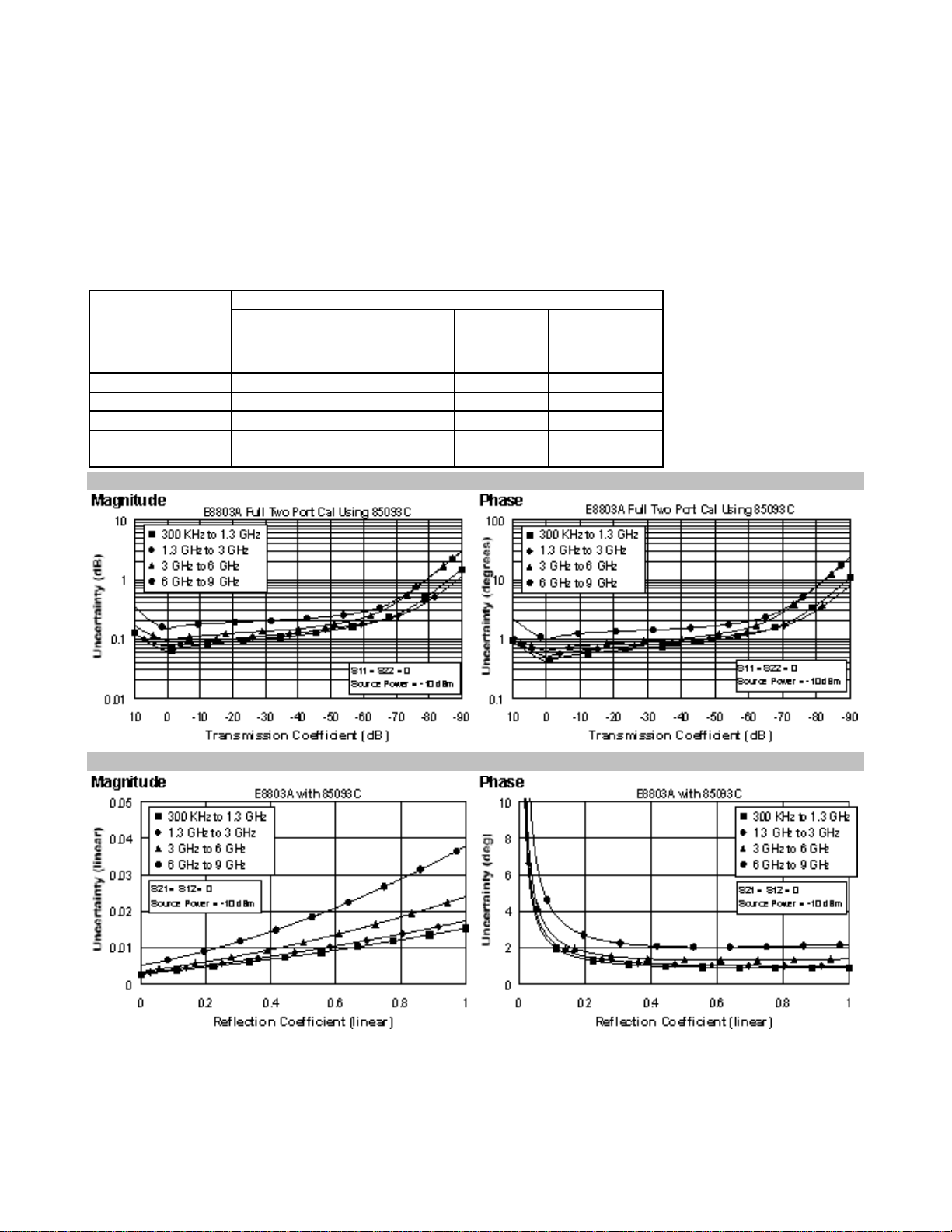
Table 5. Corrected System Performance With 3.5 mm Device Connector Type, 85093C
Electronic Calibration Module
Applies to the E8801A, E8802A, and E8803A analyzer, 85093C (3.5 mm, 50Ω) electronic calibration (ECal) module, N6314A test port c able,
and a full 2-port calibration. Also applies to the following conditions:
• IF bandwidth = 10 Hz
• No averaging applied to data
• Environmental temperature 25° ±5 °C, with < 1 °C deviation from calibration temperature
• Isolation calibration not omitted
Specification (dB) Description
300 kHz to
1.3 GHz
Directivity 52 52 51 47
Source Match 44 44 39 34
Load Match 47 47 44 40
Reflection Tracking ±0.030 ±0.040 ±0.050 ±0.070
Transmission
Tracking
Transmission Uncertainty (Specifications)
±0.039 ±0.049 ±0.068 ±0.117
1.3 GHz to
3 GHz
3 GHz to
6 GHz
6 GHz to
a
9 GHz
Reflection Uncertainty (Specifications)
7
Page 12

Table 6. Corrected System Performance With 7-16 Device Connector Type, 85038A Calibration
Kit
Applies to the E8801A, E8802A, and E8803A analyzer, 85038A (7-16, 50Ω) calibration kit, N6314A test port cable, and a full 2-port
calibration. Also applies to the following conditions:
• IF bandwidth = 10 Hz
• No averaging applied to data
• Environmental temperature 25° ±5 °C, with < 1 °C deviation from calibration temperature
• Isolation calibration not omitted
Specification (dB) Description
300 kHz to
1.3 GHz
Directivity 40 40 36 36
Source Match 37 37 34 34
Load Match 39 39 35 35
Reflection Tracking ±0.089 ±0.089 ±0.115 ±0.115
Transmission
Tracking
Transmission Uncertainty (Specifications)
±0.024 ±0.033 ±0.082 ±0.103
1.3 GHz to
3 GHz
3 to
6 GHz
6 to
9 GHz
a
Reflection Uncertainty (Specifications)
8
Page 13

Table 7. Uncorrected Instrument Performance
Specification (dB) Description
300 kHz to
1 MHz
Directivity 30 33 27 20 13
Source Match 18 18 16 11 8
Load Match 20 20 17 13.5 13
Reflection
Tracking
Transmission
Tracking
±1.5 ±1.5 ±1.5 ±2.5 ±3.0
±1.5 ±1.5 ±1.5 ±2.5 ±3.0
1MHz to
1.3 GHz
1.3 GHz to
3 GHz
3 GHz to
6 GHz
6 GHz to
9 GHz
Test Port Outp ut Characteristics (Source)
Table 8. Test Port Output Frequency
Description Specification Supplemental Information
Range:
E8801A
E8802A
E8803A
Resolution:
Source Stability
Source Stability
(Option 1E5)
CW Accuracy
CW Accuracy
(Option 1E5)
300 kHz to 3.0 GHz
300 kHz to 6.0 GHz
300 kHz to 9.0 GHz
1 Hz
±3 ppm
±1 ppm
±1 ppm, 0°C to 40 °C, typical
±1ppm/year maximum
±0.05 ppm, 0° to 70 °C, typical
±0.1 ppm/year maximum
9
Page 14

Table 9. Test Port Output Power
a
Description Specification Supplemental Information
Level Accuracy:
300 kHz to 6 GHz ±1.0 dB Variation from 0 dBm in power range 0
6 GHz to 9 GHz ±2.0 dB ±1.5dB below 10 MHz
Level Linearity:
Variation from 0 dBm in power range 0
300 kHz to 9 GHz ±0.3 dB -15 to +5 dBm
300 kHz to 1 MHz ±1.0 dB +5 to +10 dBm
1 MHz to 6 GHz ±0.5 dB +5 to +10 dBm
6 GHz to 9 GHz ±0.5 dB +5 to +7 dBm
Range
300 kHz to 6 GHz -15 to +10 dBm
6 GHz to 9 GHz -15 to +7 dBm
Range
b:
b:
(Option 1E1):
300 kHz to 6 GHz -85 to +10 dBm
6 GHz to 9 GHz -85 to +7 dBm
Sweep Range
300 kHz to 6 GHz 25 dB
6 GHz to 9 GHz 22 dB
Level Resolution
a
Source output performance on port 1 only. Port 2 output performance is typical.
b
Power to which the source can be set and phase lock is assured.
0.01 dB
10
Page 15

Table 10. Test Port Output Signal Purity
Description Specification Supplemental Information
Harmonics (2nd or 3rd)
at max output power (< 25 MHz)
at max output power (25 MHz to 9 GHz)
at 0 dBm output
at -10 dBm output
< -25 dBc, typical
< -25 dBc, characteristic
a
< -35 dBc, typical
< -38 dBc, typical, in power
range 0
Non-harmonic Spurious
at max output
at -10 dBm output
a
Typical below 25 MHz.
-30 dBc, typical for offset freq>1kHz
-50 dBc, typical for offset freq >1kHz
Test Port and Receiver Input Characteristics
Table 11. Test Port and Receiver Input Levels
Description Specification Supplemental Information
Maximum Test Port Input Level
Test Ports 1 and 2:
300 kHz to 25 MHz +10 dBm < 0.6 dB compression
25 MHz to 3 GHz +10 dBm < 0.4 dB compression
3 GHz to 6 GHz +10 dBm < 0.7 dB compression
6 GHz to 9 GHz +5 dBm < 0.7 dB compression
Damage Level
Test Port 1, 2
R, A, B (Opt. 014)
Coupler Thru (Opt. 014)
Test Port Noise Floor
300 kHz to 25 MHz
b
10 Hz IF Bandwidth -115 dBm
1 kHz IF Bandwidth -95 dBm
25 MHz to 3 GHz
b
10 Hz IF Bandwidth -118 dBm
1 kHz IF Bandwidth -98 dBm
3 GHz to 9 GHz
10 Hz IF Bandwidth
1 kHz IF Bandwidth
a
≤ -108 dBm
≤ -88 dBm
+30 dBm or ±30 VDC, typ.
+15 dBm or ±5 VDC, typ.
+33 dBm or ±0 VDC, typ.
11
Page 16

Table 11. Test Port and Receiver Input Levels (Continued)
Description Specification Supplemental Information
Receiver Noise Floor
300 kHz to 25 MHz
10 Hz IF Bandwidth
1 kHz IF Bandwidth
25 MHz to 3 GHz
10 Hz IF Bandwidth
1 kHz IF Bandwidth
6 GHz to 9 GHz
10 Hz IF Bandwidth
1 kHz IF Bandwidth
Crosstalk
300 kHz to 1 MHz <-120 dB
1 MHz to 25 MHz <-125 dB
25 MHz to 3 GHz <-126 dB
3 GHz to 6 GHz <-117 dB
6 GHz to 9 GHz <-106 dB
Maximum Receiver Input Level (A, B, R)
300 kHz to 6 GHz
6 GHz to 9 GHz
Reference Input Level (R)
300 kHz to 9 GHz
Maximum Coupler Input Level (Opt 014)
300 kHz to 9 GHz
a
Total average (RMS) noise power calculated as the mean value of a linear magnitude trace expressed in dBm.
b
May be limited to -90 dBm at particular frequencies below 750 MHz due to spurious receiver residuals.
c
May be limited to -105 dBm at particular frequencies below 750 MHz due to spurious receiver residuals.
d
Input level to maintain phase lock.
a
c
c
≤ -130 dBm
≤ -110 dBm
≤ -133 dBm
≤ -113 dBm
≤ -123 dBm
≤ -103 dBm
Between test ports 1 and 2, with
short circuits at both ports
d
-6 dBm, typical
-9 dBm, typical
-10 to -35 dBm, typical
+33 dBm, typical
12
Page 17

Table 12. Test Port Input (Trace Noise)
Description Specification Supplemental Information
Trace Noisea Magnitude
1 kHz IF Bandwidth < 0.002 dB rms
10 kHz IF Bandwidth < 0.005 dB rms
Trace Noisea Phase
1 kHz IF Bandwidth < 0.010° rms
10 kHz IF Bandwidth < 0.035° rms
a
Trace noise is defined as a ratio measurement of a through or a full reflection, with the source set to 0 dBm.
Table 13. Test Port Input (Reference Level and Stability)
Description Specification Supplemental Information
Reference Level Magnitude
Range ±200 dB
Resolution 0.001 dB
Reference Level Phase
Range ±500°
Resolution 0.01°
Stability Magnitude
300 kHz to 3 GHz
3 GHz to 6 GHz
6 GHz to 9 GHz
Stability Phase
300 kHz to 3 GHz
a
a
3 GHz to 6 GHz
6 GHz to 9 GHz
a
Stability is defined as a ratio measurement at the test port.
0.02 dB/°C, typical
0.04 dB/°C, typical
0.06 dB/°C, typical
0.2°/°C, typical
0.3°/°C, typical
0.6°/°C, typical
13
Page 18

Table 14. Test Port Input (Dynamic Accuracy specificationa)
Accuracy of the test port input power reading is relative to the reference input power level. Applies to input ports 1 and 2 with the following
conditions: IF bandwidth = 10 Hz, and Environmental temperature 25° ±5 °C, with < 1 °C deviation from calibration temperature
300 kHz to 3 GHz 300 kHz to 3 GHz
300 kHz to 6 GHz 300 kHz to 6 GHz
300 kHz to 9 GHz 300 kHz to 9 GHz
a
Dynamic accuracy is verified with the following measurements:
• compression over frequency
• IF linearity at a single frequency of 1.195 GHz and a reference level of -20 dBm
14
Page 19
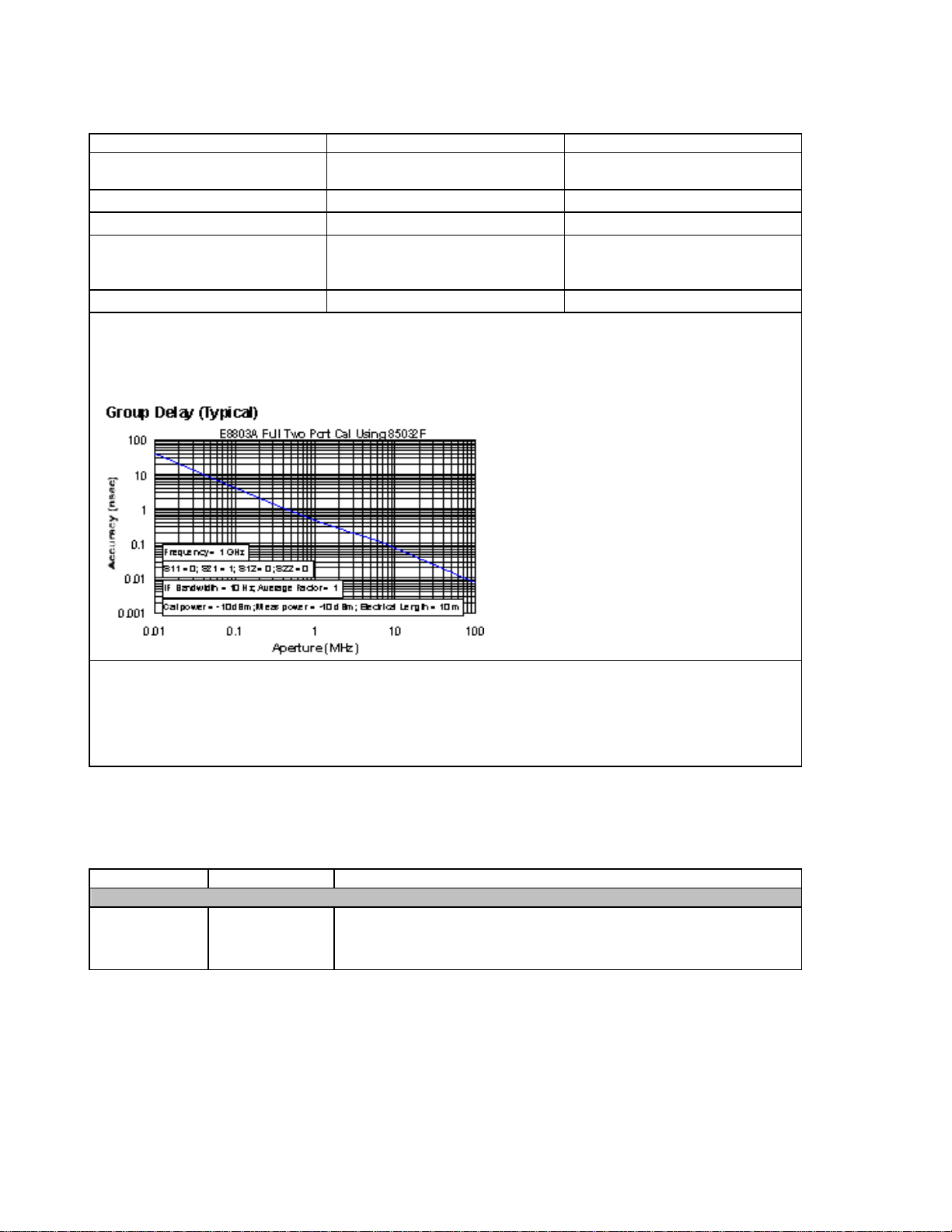
Table 15. Test Port Input (Group Delay)
Description Specification Supplemental Information
Aperture (selectable) (frequency span)/(number of
points -1)
Maximum Aperture 20% of frequency span
Range 0.5 x (1/minimum aperture)
Maximum Delay
Accuracy
The following graph shows group delay accuracy with type-N full 2-port calibration and a 10 Hz IF
bandwidth. Insertion loss is assumed to be < 2 dB and electrical length to be ten meters.
a
Limited to measuring no more
than 180° of phase change within
the minimum aperture.)
See graph below. Char.
In general, the following formula can be used to determine the accuracy, in seconds, of specific group
delay measurement:
±Phase Accuracy (deg)/[360 × Aperture (Hz)]
Depending on the aperture and device length, the phase accuracy used is either incremental phase
accuracy or worst ca se phase accuracy.
a
Group delay is computed by measuring the phase change within a specified frequency step (determined by the frequency span and the
number of points per sweep).
General Inform a t io n
Table 16. System Bandwidths
Description Specification Supplemental Information
IF Bandwidth Settings
Range
1 Hz to 40 kHz
in a 1, 2, 3, 5, 7,10 sequence up to 30 kHz, 35 kHz, 40kHz,
nominal
15
Page 20

Table 17. Front Panel Information
Description Supplemental Information
RF Connectors
Type
Center Pin Protrusion 0.204 to 0.207 in., characteristic
Probe Power
Connector 3-pin connector, male
Positive Supply +15 VDC ±2%, 400 mA, max, characteristic
Negative Supply -12.6 VDC ±5%, 300 mA, max, characteristic
Display
Size 21.3 cm (8.4 in) diagonal color active matrix LCD; 640 (horizontal) X 480
Refresh Rate Vertical 59.83 Hz; Horizontal 31.41 Hz
Display Range
Magnitude
Phase ±180°, max
Polar
Display Resolution
Magnitude 0.001 dB/div, min
Phase 0.01°/div, min
Marker Resolution
Magnitude 0.001 dB, min
Phase 0.01°, min
Polar 0.01 mUnit, min; 0.01°,min
Type-N, female; 50 Ω, nominal
(vertical) resolution
±200 dB (at 20 dB/div), max
10 pUnits, min
1000 Units, max
16
Page 21

Table 18. Rear Panel Information
Description Supplemental Information
10 MHz Reference In
Connector BNC, female
Input Frequency 10 MHz ± 1 ppm, typical
Input Level -15 dBm to +20 dBm, typical
Input Impedance
10 MHz Reference Out
Connector BNC, female
Output Frequency 10 MHz ± 10 ppm, typical
Signal Type Sine Wave, ty pi cal
Output Level
Output Impedance
Harmonics <-40 dBc, typical
VGA Video Output
Connector 15-pin mini D-Sub; Drives VGA compatible monitors
Devices Supported Resolutions
Flat Panel (TFT 1024 X 768, 800 X 600, 640 X 480
Flat Panel (DSTN) 800 X 600, 640 X 480
CRT Monitor 1280 X 1024, 1024 X 768, 800 X 600, 640 X 480
Test Set IO
Aux IO
Handler IO
GPIB
Parallel Port (LPT1)
Serial Port (COM 1)
USB Port
Contact 1 Vcc: 4.75 to 5.25 VDC, 500 mA, maximum
Contact 2 -Data
Contact 3 +Data
Contact 4 Ground
LAN
Line Power
a, b
Frequency at 110/115 V 50/60/400 Hz
Frequency at 230/240 V 50/60 Hz
Maximum Watts 350 W
a
A third-wire ground is required.
b
Power supply has a voltage autoswitching feature.
Note: Option H08 and Option H11 specifications are not provided in this E8801/2/3A specifications document.
200 Ω, nom.
+10 dBm ± 4 dB into 50 Ω, typical
50 Ω, nominal
Simultaneous operation of the internal and external displays is allowed,
but with 640 X 480 resolution only. If you change resolution, you can only
view the external display (internal display will "white out").
25-pin D-Sub connector, available for external test set control
25-pin D-Sub connector, male, analog and digital IO
36-pin IDC D-ribbon socket connector; all input/output signals are default
set to negative logic; can be reset to positive logic via GPIB command
24-pin D-sub (Type D-24), female; compatible with IEEE-488.
25-pin D-Sub connector, female; provides connection to printers or any
other parallel port peripherals
9-pin D-Sub, male; compatible with RS-232
Universal Serial Bus jack, Type A configuration (4 contacts inline, contact
1 on left); female
10/100BaseT Ethernet, 8-pin configuration; auto selects between the two
data rates
17
Page 22

Table 19. Rear Panel Information (continued)
Description Supplemental Information
External AM Input
Description Input provides low-frequency AM modulation to test port output
signal, or shifts the test port output. Zero volts input gives the power
level set by the instrument, a positive voltage gives a higher level,
and a negative voltage gives a lower level.
Connector BNC, female
Input Sensitivity 8 dB/V, typical
Bandwidth 1 kHz, typical
Input Impedance
External Detector Input
Description Input from an external, negative polarity diode detector provides
Connector BNC, female
Input Sensitivity -500 mV yields approximately -3 dBm at detector's input, typical
Bandwidth 50 kHz, typical
Input Impedance
1 kΩ, typical
ALC for a test port remote from instrument's front panel
1 kΩ, nominal
18
Page 23

Table 20. Analyzer Environment and Dimensions
Description Supplemental Information
General Environmental
RFI/EMI Susceptibility Defined by CISPR Pub. 11, Group 1, Class A, and IEC
50082-1
ESD Minimize using static-safe work procedures and an
antistatic bench mat
Dust Minimize for optimum reliability
Operating Environment
Temperature
Error-Corrected Temperature Range 25°C ± 5°C
Humidity 5% to 95% at +40 °C
Altitude 0 to 4500 m (14,760 ft.)
Non-Operating Storage Environment
Temperature -40 °C to +70 °C
Humidity 0% to 90% at +65 °C (non-condensing)
Altitude 0 to 15,240 m (50,000 ft.)
Cabinet Dimensions
Excluding front and rear
panel hardware and feet
As shipped - includes front
panel connectors, rear
panel bumpers, and feet.
As shipped plus handles 235 mm
As shipped plus rackmount flanges
As shipped plus handles
and flanges
Weight
Net 24 kg (54 lb), nominal
Shipping 32 kg (70 lb), nominal
Note: "Misc. Information" specifications are not included in this E8801/2/3A document.
Height Width Depth
223 mm
8.75 in
235 mm
9.25 in
9.25 in
235 mm
9.25 in
235 mm
9.25 in
0 °C to +40 °C
Instrument powers up, phase locks, and displays no
error messages within this temperature range.
with less than 1°C deviation from calibration temp.
426 mm
16.75 in
435 mm
17.10 in
458 mm
18 in
483 mm
19 in
483 mm
19 in
427 mm
16.8 in
470 mm
18.5 in
501 mm
19.70 in
470 mm
18.5 in
501 mm
19.70 in
19
Page 24
Measurement Throughput Summary
Table 21. Typical Cycle Time
Start 1.8 GHz, Stop 2 GHz, 35 kHz IF bandwidth
Uncorrected,
1-port cal
2-Port cal 27 36 55 164
Start 300 kHz, Stop 3 GHz, 35 kHz IF bandwidth
Uncorrected,
1-port cal
2-Port cal 103 119 145 254
Start 300 kHz, Stop 9 GHz, 35 kHz IF bandwidth
Uncorrected,
1-port cal
2-Port cal 112 124 138 220
a Typical performance.
b Includes sweep time, retrace time and band-crossing time. Analyzer display turned off with
DISPLAY:ENABLE OFF. Add 21 ms for display on. Data for one trace (S11) measurement..
Number of Points
101 201 401 1601
7 10 16 52
48 54 64 104
51 57 64 103
Table 22. Cycle Time vs. IF Bandwidth
Applies to the Preset c onditi on (201 points, correction off) except for the following changes:
a,b
(ms)
a
• CF = 1 GHz
• Span = 100 MHz
• Display off (add 21 ms for display on)
IF Bandwidth
(Hz)
Cycle Time (ms)
40,000 8
35,000 9
30,000 11
20,000 13
10,000 28
7000 36
5000 48
3000 72
1000 196
300 620
100 1875
30 8062
10 17877
a
Typical performance.
b
Cycle time includes sweep and retrace time.
b
20
Page 25

Table 23. Cycle Time vs. Number of Points
Applies to the Preset condition (35 kHz IF bandwidth, correction off) except for t he following changes:
a
• CF = 1 GHz
• Span = 100 MHz
• Display off (add 21 ms for display on)
Number of
Points
Cycle Time (ms)
b
3 4
11 4
51 5
101 6
201 9
401 16
801 29
1601 52
a
Typical performance.
b
Cycle time includes sweep and retrace time.
21
Page 26

Table 24. Data Transfer Timea (ms)
SCPI over GPIB
(program executed on external PC)
32-bit floating point 3 7 12 43
64-bit floating point 4 12 22 84
ASCII 7 64 24 489
SCPI over 100 Mbit/s LAN
(program executed on external PC)
32-bit floating point 1 1 1 1
64-bit floating point 1 1 1 2
ASCII 5 15 26 96
SCPI (program executed in the analyzer)
32-bit floating point 1 1 2 3
64-bit floating point 1 2 2 4
ASCII 8 29 56 222
COM (program executed in the analyzer)
32-bit floating point 1 1 1 1
Variant type 1 1 2 6
DCOM over 100 Mbit/s LAN
(program executed on external PC)
32-bit floating point
Variant type
a
Typical performance of unit with 500 MHz Pentium III processor.
b
Measured using a VEE 5.0 program running on a 600 MHz HP Kayak, National InstrumentsTM GPIB card.
Transferred complex S11 data , using "CALC:DATA?SDATA".
c
Measured using a VEE 5.0 program running on a 600 MHz HP Kayak. Transferred complex S11 data,
using "CALC:DATA?SDATA". Speed dependent on LAN traffic, if connected to network.
d
Measured using a VEE 5.0 program running inside PNA Series Analyzer. Transferred complex S11 data,
using "CALC:DATA?SDA TA".
e
Measured using a Visual Basic 6.0 program running inside PNA Series Analyzer. Transferred complex S11
data.
f
Measured using a Visual Basic 6.0 program running on a 600 MHz HP Kayak. Transferred
complex S11 data. Speed dependent on LAN traffic, if connected to network.
g
Used IArray Transfer.getComplex method for 32-bit floating point.
h
Used meas.getData method for Variant data type.
h
1 3 6 19
Number of Points
51 201 401 1601
b
b
d
e
f
g
1 1 1 2
22
Page 27

Table 25. Recall and Sweep Speed
Operations
Number of
Window(s)
a
Number of
Trace(s)
Recall
Time (ms)
Recall 1 1 49
Recall and Sweep 1 1 59
Recall 1 2 82
Recall and Sweep 1 2 96
Recall 1 4 159
Recall and Sweep 1 4 203
Recall 2 2 93
Recall and Sweep 2 2 115
Recall 3 4 158
Recall and Sweep 3 4 218
Recall 4 4 187
Recall and Sweep 4 4 247
Recall 4 8 340
Recall and Sweep 4 8 507
a
CF=177 MHz, Span=200 MHz, 201 points, 35 kHz IF BW
23
Page 28

E8801A, E8802A, and E8803A Simplified Test Set Block Diagram
24
Page 29
E8801A, E8802A, and E8803A with Option 014 Simplified Test Set Block Diagram
25
Page 30

www.agilent.com/find/emailupdates
Get the latest information on the products and
applications you select.
Agilent Email Updates
www.agilent.com
Agilent Technologies’ Test and Measurement
Support, Services, and Assistance
Agilent Technologies aims to maximize the value you
receive, while minimizing your risk and problems. We
strive to ensure that you get the test and measurement
capabilities you paid for and obtain the support you
need. Our extensive support resources and services
can help you choose the right Agilent products for
your applications and apply them successfully. Every
instrument and system we sell has a global warranty.
Two concepts underlie Agilent’s overall support policy:
“Our Promise” and “Your Advantage.”
Our Promise
Our Promise means your Agilent test and measurement
equipment will meet its advertised performance
and functionality. When you are choosing new equipment, we will help you with product information,
including realistic performance specifications and
practical recommendations from experienced test
engineers. When you receive your new Agilent equipment, we can help verify that it works properly and
help with initial product operation.
Your Advantage
Your Advantage means that Agilent offers a wide
range of additional expert test and measurement
services, which you can purchase according to your
unique technical and business needs. Solve problems
efficiently and gain a competitive edge by contracting
with us for calibration, extra-cost upgrades, out-ofwarranty repairs, and onsite education and training,
as well as design, system integration, project management, and other professional engineering services.
Experienced Agilent engineers and technicians worldwide can help you maximize your productivity, optimize
the return on investment of your Agilent instruments
and systems, and obtain dependable measurement
accuracy for the life of those products.
For more information on Agilent Technologies’
products, applications or services, please contact
your local Agilent office.
Phone or Fax
United States: Korea:
(tel) 800 829 4444 (tel) (080) 769 0800
(fax) 800 829 4433 (fax) (080) 769 0900
Canada: Latin America:
(tel) 877 894 4414 (tel) (305) 269 7500
(fax) 800 746 4866 Taiwan:
China: (tel) 0800 047 866
(tel) 800 810 0189 (fax) 0800 286 331
(fax) 800 820 2816 Other Asia Pacific
Europe: Countries:
(tel) 31 20 547 2111 (tel) (65) 6375 8100
Japan: (fax) (65) 6755 0042
(tel) (81) 426 56 7832 Email: tm_ap@agilent.com
(fax) (81) 426 56 7840
Contacts revised: 09/26/05
The complete list is available at:
www.agilent.com/find/contactus
Product specifications and descriptions in this
document subject to change without notice.
© Agilent Technologies, Inc. 2004, 2006
Printed in USA, July 13, 2006
5989-1075ENUS
www.agilent.com/find/agilentdirect
Quickly choose and use your test equipment
solutions with confidence.
Agilent Direct
Agilent
Open
www.agilent.com/find/open
Agilent Open simplifies the process of connecting
and programming test systems to help engineers
design, validate and manufacture electronic products. Agilent offers open connectivity for a broad
range of system-ready instruments, open industry
software, PC-standard I/O and global support,
which are combined to more easily integrate test
system development.
 Loading...