

Page 1

Technical Specifications
Agilent Technologies
PNA Series Network Analyzers
E8362B/C, E8363B/C, and E8364B/C
Manufacturing Part Number: E8364-90031
Printed in USA
Print Date: October 3, 2008
Supersedes: September 8, 2008
© Agilent Technologies, Inc. 2004, 2006 - 2008 All rights reserved.
Page 2

Documentation Warranty
THE MATERIAL CONTAINED IN THIS DOCUMENT IS PROVIDED "AS IS," AND IS
SUBJECT TO BEING CHANGED, WITHOUT NOTICE, IN FUTURE EDITIONS. FURTHER, TO THE MAXIMUM EXTENT PERMITTED BY APPLICABLE LAW, AGILENT
DISCLAIMS ALL WARRANTIES, EITHER EXPRESS OR IMPLIED WITH REGARD TO
THIS MANUAL AND ANY INFORMATION CONTAINED HEREIN, INCLUDING BUT
NOT LIMITED TO THE IMPLIED WARRANTIES OF MERCHANTABILITY AND FITNESS FOR A PARTICULAR PURPOSE. AGILENT SHALL NOT BE LIABLE FOR
ERRORS OR FOR INCIDENTAL OR CONSEQUENTIAL DAMAGES IN CONNECTION
WITH THE FURNISHING, USE, OR PERFORMANCE OF THIS DOCUMENT OR ANY
INFORMATION CONTAINED HEREIN. SHOULD AGILENT AND THE USER HAVE A
SEPARATE WRITTEN AGREEMENT WITH WARRANTY TERMS COVERING THE
MATERIAL IN THIS DOCUMENT THAT CONFLICT WITH THESE TERMS, THE WARRANTY TERMS IN THE SEPARATE AGREEMENT WILL CONTROL.
DFARS/Restricted Rights Notice
If software is for use in the performance of a U.S. Government prime contract or
subcontract, Software is delivered and licensed as “Commercial computer software” as
defined in DFAR 252.227-7014 (June 1995), or as a “commercial item” as defined in FAR
2.101(a) or as “Restricted computer software” as defined in FAR 52.227-19 (June 1987) or
any equivalent agency regulation or contract clause. Use, duplication or disclosure of
Software is subject to Agilent Technologies’ standard commercial license terms, and
non-DOD Departments and Agencies of the U.S. Government will receive no greater than
Restricted Rights as defined in FAR 52.227-19(c)(1-2) (June 1987). U.S. Government users
will receive no greater than Limited Rights as defined in FAR 52.227-14 (June 1987) or
DFAR 252.227-7015 (b)(2) (November 1995), as applicable in any technical data.
Printing Copies of Documentation from the Web
To print copies of documentation from the Web, download the PDF file from the Agilent
web site:
•Go to www.agilent.com.
• Enter the document’s part number (located on the title page) in the Search box.
• Click SEARCH.
• Click on the hyperlink for the document.
• Click the printer icon located in the tool bar.
Page 3

Contacting Agilent
Assistance with test and measurement needs and information on finding a local Agilent
office are available on the Web at:
www.agilent.com/find/assist
If you do not have access to the Internet, please contact your Agilent field engineer.
NOTE
In any correspondence or telephone conversation, refer to the Agilent product
by its model number and full serial number. With this information, the
Agilent representative can determine whether your product is still within its
warranty period.
Page 4

This page intentionally left blank.
Page 5

Technical Specifications for the E8362B/C, E8363B/C, E8364B/C (Rev. 2008-10-03)
Definitions.................................................................................................................................................. 4
Corrected System Performance ............................................................................................................... 4
Table 1. System Dynamic Range........................................................................................................ 5
Table 2. Receiver Dynamic Range ..................................................................................................... 7
E8363B/C AND E8364B/C Corrected System Performance with 2.4mm Connectors.................... 9
Table 3. 85056A Calibration Kit Standard Configuration and
Standard Power Range (E8363B/C AND E8364B/C) ...................................................................... 9
Table 4. 85056A Calibration Kit Fully Optioned (E836xB/C - Option 014, UNL, 016, 080, and
081) ................................................................................................................................................... 12
Table 5. 85056D Calibration Kit Standard Configuration and
Standard Power Range (E8363B/C AND E8364B/C) .................................................................... 15
Table 6. 85056D Calibration Kit Fully Optioned (E836xB/C - Option 014, UNL, 016, 080, and
081) ................................................................................................................................................... 18
E8363B/C AND E8364B/C Corrected System Performance with 2.92mm Connectors................ 21
Table 7. 85056K Calibration Kit Standard Configuration and
Standard Power Range (E8363B/C AND E8364B/C) .................................................................... 21
Table 8. 85056K Calibration Kit Fully Optioned (E836xB/C - Option 014, UNL, 016, 080, and
081) ................................................................................................................................................... 24
E836xB/C Corrected System Performance with 3.5mm Connectors.............................................. 27
Table 9. 85052B Calibration Kit Standard Configuration and
Standard Power Range (E836xB/C)................................................................................................ 27
Table 10. 85052B Calibration Kit Fully Optioned (E836xB/C - Option 014, UNL, 016, 080, and
081) ................................................................................................................................................... 30
Table 11. 85052C Calibration Kit Standard Configuration and
Standard Power Range (E836xB/C)................................................................................................ 33
Table 12. 85052C Calibration Kit Fully Optioned (E836xB/C - Option 014, UNL, 016, 080, and
081) ................................................................................................................................................... 36
Table 13. 85052D Calibration Kit Standard Configuration and
Standard Power Range (E836xB/C)................................................................................................ 39
Table 14. 85052D Calibration Kit Fully Optioned (E836xB/C - Option 014, UNL, 016, 080,
and 081).............................................................................................................................................42
E836xB/C Corrected System Performance with 7mm Connectors ................................................ 45
Table 15. 85050B Calibration Kit Standard Configuration and
Standard Power Range (E836xB/C)................................................................................................ 45
Table 16. 85050B Calibration Kit Fully Optioned (E836xB/C - Option 014, UNL, 016, 080,
and 081).............................................................................................................................................48
Table 17. 85050C Calibration Kit Standard Configuration and
Standard Power Range (E836xB/C)................................................................................................ 51
Table 18. 85050C Calibration Kit Fully Optioned (E836xB/C - Option 014, UNL, 016, 080, and
081) ................................................................................................................................................... 54
Table 19. 85050D Calibration Kit Standard Configuration and
Standard Power Range (E836xB/C)................................................................................................ 57
Table 20. 85050D Calibration Kit Fully Optioned (E836xB/C - Option 014, UNL, 016, 080, and
081) ................................................................................................................................................... 60
E836xB/C Corrected System Performance with Type-N Connectors ............................................ 63
Table 21. 85054B Calibration Kit Standard Configuration and
1
Page 6

Standard Power Range (E836xB/C)................................................................................................ 63
Table 22. 85054B Calibration Kit Fully Optioned (E836xB/C - Option 014, UNL, 016, 080, and
081) ................................................................................................................................................... 66
Table 23. 85054D Calibration Kit Standard Configuration and
Standard Power Range (E836xB/C)................................................................................................ 69
Table 24. 85054D Calibration Kit Fully Optioned (E836xB/C - Option 014, UNL, 016, 080,
and 081).............................................................................................................................................72
E8363B/C AND E8364B/C Corrected System Performance with WR-28 Connectors ................. 75
Table 25. R11644A Calibration Kit Standard Configuration and
Standard Power Range (E8363B/C AND E8364B/C) .................................................................... 75
Table 26. R11644A Calibration Kit Fully Optioned (E836xB/C - Option 014, UNL, 016, 080,
and 081).............................................................................................................................................78
E8363B/C AND E8364B/C Corrected System Performance with WR-42 Connectors ................. 81
Table 27. K11644A Calibration Kit Standard Configuration and
Standard Power Range (E8363B/C AND E8364B/C) .................................................................... 81
Table 28. K11644A Calibration Kit Fully Optioned (E836xB/C - Option 014, UNL, 016, 080,
and 081).............................................................................................................................................84
E836xB/C Corrected System Performance with WR-62 Connectors ............................................. 87
Table 29. P11644A Calibration Kit Standard Configuration and
Standard Power Range (E836xB/C)................................................................................................ 87
Table 30. P11644A Calibration Kit Fully Optioned (E836xB/C - Option 014, UNL, 016, 080,
and 081).............................................................................................................................................90
E836xB/C Corrected System Performance with WR-90 Connectors ............................................. 93
Table 31. X11644A Calibration Kit Standard Configuration and
Standard Power Range (E836xB/C)................................................................................................ 93
Table 32. X11644A Calibration Kit Fully Optioned (E836xB/C - Option 014, UNL, 016, 080, and
081) ................................................................................................................................................... 96
Table 33. Uncorrected System Performance .................................................................................... 99
Table 34. Test Port Output .............................................................................................................102
Table 35: Test Port Input................................................................................................................ 106
Table 36. Dynamic Accuracy (Specification)................................................................................. 113
Table 37. Test Port Input (Group Delay) ........................................................................................ 117
General Information ............................................................................................................................. 118
Table 38. Miscellaneous Information ..........................................................................................118
Table 39. Front Panel Information.................................................................................................. 118
Table 40. Rear Panel Information...................................................................................................119
Table 41. Analyzer Dimensions and Weight .................................................................................. 122
Measurement Throughput Summary.................................................................................................. 123
Table 42 Typical Cycle Time (ms) for Measurement Completion ................................................. 123
Table 43. Cycle Time vs IF Bandwidth.......................................................................................... 124
Table 44. Cycle Time vs Number of Points.................................................................................... 124
Table 45. Frequency Converter Application (option 083) Cycle Time for
Fixed-IF Measurements .................................................................................................................. 125
Table 46. Data Transfer Time (ms) ................................................................................................ 125
Specifications: Front-Panel Jumpers
Table 47: Measurement Receiver Inputs (Rcvr A In, Rcvr B In)................................................... 126
................................................................................................... 126
2
Page 7

Table 48: Reference Receiver Inputs (Rcvr R1, Rcvr R2) ............................................................. 128
Table 49: Reference Outputs (Reference 1 Source Out, Reference 2 Source Out) ........................129
Table 50: Source Outputs (Port 1 Source Out, Port 2 Source Out) ................................................ 130
Table 51: Coupler Inputs (Port 1 Cplr Thru, Port 2 Cplr Thru)...................................................... 132
Table 52: Coupler Outputs (Port 1 Cplr Arm, Port 2 Cplr Arm).................................................... 133
Test Set Block Diagrams....................................................................................................................... 134
E836xB/C - Standard Configuration and Standard Power Range....................................................... 134
E836xB/C - Option UNL Standard Configuration with Extended Power Range and Bias - Tees...... 134
E836xB/C - Option UNL Standard Configuration with Extended Power Range and Bias - Tees, and
Option 016, Receiver Attenuators....................................................................................................... 135
Test Set with Option 014 Block Diagrams ..........................................................................................136
E836xB/C - Option 014 Configurable Test Set and Standard Power Range......................................136
E836xB/C - Option 014 Configurable Test Set and Standard Power Range, and
Option 081 Reference Channel Transfer Switch ................................................................................. 137
E836xB/C - Option 014 Configurable Test Set, and Option UNL Extended Power Range and
Bias - Tees........................................................................................................................................... 138
E836xB/C - Option 014 Configurable Test Set, and Option UNL Extended Power Range
and Bias - Tees, and Option 081 Reference Channel Transfer Switch ............................................... 139
E836xB/C - Option 014 Configurable Test Set and Option UNL, Extended Power Range and
Bias - Tees and Option 016 Receiver Attenuators .............................................................................. 140
E836xB/C - Option 014 Configurable Test Set, and Option UNL Extended Power Range and
Bias - Tees, and Option 016 Receiver Attenuators, and Option 081 Reference Channel
Transfer Switch ................................................................................................................................... 141
3
Page 8

Definitions
All specifications and characteristics apply over a 25 °C ±5 °C range (unless otherwise stated) and 90 minutes
after the instrument has been turned on.
Specification (spec.): Warranted performance. Specifications include guardbands to account for the expected
statistical performance distribution, measurement uncertainties, and changes in performance due to
environmental conditions.
Characteristic (char.): A performance parameter that the product is expected to meet before it leaves the
factory, but that is not verified in the field and is not covered by the product warranty. A characteristic includes
the same guardbands as a specification.
Typical (typ.): Expected performance of an average unit which does not include guardbands. It is not covered
by the product warranty.
Nominal (nom.): A general, descriptive term that does not imply a level of performance. It is not covered by the
product warranty.
Calibration: The process of measuring known standards to characterize a network analyzer's systematic
(repeatable) errors.
Corrected (residual): Indicates performance after error correction (calibration). It is determined by the quality of
calibration standards and how well "known" they are, plus system repeatability, stability, and noise.
Uncorrected (raw): Indicates instrument performance without error correction. The uncorrected performance
affects the stability of a calibration.
Standard: When referring to the analyzer, this includes no options unless noted otherwise.
⎯⎯⎯⎯⎯⎯⎯⎯⎯⎯⎯⎯⎯⎯⎯⎯⎯⎯⎯⎯⎯⎯⎯⎯⎯⎯⎯⎯⎯⎯⎯⎯⎯⎯⎯⎯⎯⎯⎯⎯⎯⎯⎯⎯
Corrected System Performance
The specifications in this section apply for measurements made with the E836xB/C analyzer with the following
conditions:
10 Hz IF bandwidth
No averaging applied to data
Isolation calibration with an averaging factor of 8
4
Page 9

Table 1. System Dynamic Range
Description Specification
(dB) at Test
Port
a
Typical (dB) at Direct
b
Receiver Access Input
Supplemental Information
c
Dynamic Range (in a 10 Hz BW)
Standard Configuration and Standard Power Range (E836xB/C - Standard)
10 MHz to 45 MHz
45 MHz to 500 MHz
d
79 (typical) NA --
e
94 NA --
500 MHz to 2 GHz 119 NA -2 GHz to 10 GHz 122 NA -10 GHz to 20 GHz 123 NA -20 GHz to 30 GHz 114 NA -30 GHz to 40 GHz 110 NA -40 GHz to 45 GHz 109 NA -45 GHz to 50 GHz 104 NA --
Configurable Test Set and Standard Power Range (E836xB/C - Option 014)
10 MHz to 45 MHz
45 MHz to 500 MHz
d
79 (typical) 129
e
94 132
Option 016 degrades
performance by 2 dB.
500 MHz to 2 GHz 119 138
2 GHz to 10 GHz 122 137
10 GHz to 20 GHz 121 136
20 GHz to 30 GHz 111 123
30 GHz to 40 GHz 107 119
40 GHz to 45 GHz 105 116
45 GHz to 50 GHz 100 111
Standard Configuration and Extended Power Range & Bias-Tees (E836xB/C - Option UNL)
10 MHz to 45 MHz
45 MHz to 500 MHz
d
79 (typical) NA
e
92 NA
Option 016 degrades
performance by 2 dB.
500 MHz to 2 GHz 117 NA
2 GHz to 10 GHz 120 NA
10 GHz to 20 GHz 121 NA
20 GHz to 30 GHz 112 NA
30 GHz to 40 GHz 108 NA
40 GHz to 45 GHz 105 NA
45 GHz to 50 GHz 99 NA
Configurable Test Set and Extended Power Range & Bias-Tees (E836xB/C - Option 014/UNL)
10 MHz to 45 MHz
45 MHz to 500 MHz
500 MHz to 2 GHz
2 GHz to 10 GHz
10 GHz to 20 GHz
d
79 (typical) 129
e, f
92 130
f
117 136
f
120 135
g
119 134
Option 016 degrades
performance by 2 dB.
20 GHz to 30 GHz 109 121
30 GHz to 40 GHz 105 117
40 GHz to 45 GHz 101 112
45 GHz to 50 GHz 95 106
a
The system dynamic range is calculated as the difference between the noise floor and the source maximum output power. System
dynamic range is a specification when the source is set to Port 1, and a characteristic when the source is set to Port 2. The effective
dynamic range must take measurement uncertainties and interfering signals into account as well as the insertion loss resulting from a thru
cable connected between Port 1 and Port 2..
b
The test port system dynamic range is calculated as the difference between the test port noise floor and the source maximum output
power. The effective dynamic range must take measurement uncertainties and interfering signals into account as well as the insertion loss
resulting from a thru cable connected between Port 1 and Port 2..
c
The direct receiver access input system dynamic range is calculated as the difference between the receiver access input noise floor and
the source maximum output power. The effective dynamic range must take measurement uncertainties and interfering signals into account.
This set-up should only be used when the receiver input will never exceed its damage level. When the analyzer is in segment sweep mode,
5
Page 10

the analyzer can have predefined frequency segments which will output a higher power level when the extended dynamic range is required
(i.e. devices with high insertion loss), and reduced power when receiver damage may occur (i.e. devices with low insertion loss). The
extended range is only available in one-path transmission measurements.
d
Typical performance.
e
May be limited to 100 dB at particular frequencies below 500 MHz due to spurious receiver residuals. Methods are available to regain the
full dynamic range.
f
E8362B/C only: Option H11 decreases value by 1 dB.
g
E8362B/C only: Option H11 decreases value by 2 dB.
6
Page 11

Table 2. Receiver Dynamic Range
Description Specification
(dB) at Test
b
Port
a
Typical (dB) at Direct
Receiver Access Input
c
Dynamic Range (in a 10 Hz BW)
Standard Configuration and Standard Power Range (E836xB/C - Standard)
OR
Standard Configuration and Extended Power Range & Bias Tees (E836xB/C - Option UNL)
10 MHz to 45 MHz
45 MHz to 500 MHz
d
82 (typical) NA --
e
94 NA --
500 MHz to 2 GHz 119 NA -2 GHz to 10 GHz 122 NA -10 GHz to 20 GHz 125 NA -20 GHz to 30 GHz 114 NA
30 GHz to 40 GHz 111 NA
Option 016 degrades
performance by 2 dB.
40 GHz to 50 GHz 111 NA
Configurable Test Set and Standard Power Range (E836xB/C - Option 014)
OR
Configurable Test Set and Extended Power Range & Bias Tees (E836xB/C - Option 014/UNL)
10 MHz to 45 MHz
45 MHz to 500 MHz
d
82 (typical) 132 --
e
94 132 --
500 MHz to 2 GHz 119 138 -2 GHz to 10 GHz 122 137 -10 GHz to 20 GHz 124 139 -20 GHz to 30 GHz 113 125
30 GHz to 40 GHz 110 122
Option 016 degrades
performance by 2 dB.
40 GHz to 50 GHz 109 120
a
The receiver dynamic range is calculated as the difference between the noise floor and the receiver maximum output power. The effective
dynamic range must take measurement uncertainties and interfering signals into account.
b
The test port receiver dynamic range is calculated as the difference between the test port noise floor and the receiver maximum input
level. The effective dynamic range must take measurement uncertainties and interfering signals into account.
c
The direct receiver access input receiver dynamic range is calculated as the difference between the direct receiver access input noise floor
and the receiver maximum input level. The effective dynamic range must take measurement uncertainties and interfering signals into
account. This set-up should only be used when the receiver input will never exceed its compression or damage level. When the analyzer is
in segment sweep mode, the analyzer can have predefined frequency segments which will output a higher power level when the extended
dynamic range is required (i.e. devices with high insertion loss), and reduced power when compression or receiver damage may occur (i.e.
devices with low insertion loss). The extended range is only available in one-path transmission measurements.
d
Typical performance.
e
May be degraded by 10 dB at particular frequencies (multiples of 5 MHz) below 500 MHz due to spurious receiver residuals. Methods are
available to regain the full dynamic range.
Note: This E836xB/C document provides technical specifications for the following calibration kits only: 85056A,
85056D, 85056K, 85052B, 85052C, 85052D, 85050B, 85050C, 85050D, 85054B, 85054D, K11644A, P11644A,
R11644A, and the X11644A.
7
Page 12

a
Table 2 (Continued). Receiver Dynamic Range
Description
Specification
(dB) at Test
b
Port
Typical (dB) at Direct
Receiver Access Input
c
Dynamic Range (in a 10 Hz BW)
Standard Configuration and Standard Power Range (E836xB/C - Standard)
OR
Standard Configuration and Extended Power Range & Bias Tees (E836xB/C - Option UNL)
10 MHz to 45 MHz
45 MHz to 500 MHz
d
82 (typical) NA --
e
94 NA --
500 MHz to 2 GHz 119 NA -2 GHz to 10 GHz 122 NA -10 GHz to 20 GHz 125 NA -20 GHz to 30 GHz 114 NA
30 GHz to 40 GHz 111 NA
Option 016 degrades
performance by 2 dB.
40 GHz to 50 GHz 111 NA
Configurable Test Set and Standard Power Range (E836xB/C - Option 014)
OR
Configurable Test Set and Extended Power Range & Bias Tees (E836xB/C - Option 014/UNL)
10 MHz to 45 MHz
45 MHz to 500 MHz
d
82 (typical) 132 --
e
94 132 --
500 MHz to 2 GHz 119 138 -2 GHz to 10 GHz 122 137 -10 GHz to 20 GHz 124 139 -20 GHz to 30 GHz 113 125
30 GHz to 40 GHz 110 122
Option 016 degrades
performance by 2 dB.
40 GHz to 50 GHz 109 120
a
The receiver dynamic range is calculated as the difference between the noise floor and the receiver maximum output power. The effective
dynamic range must take measurement uncertainties and interfering signals into account.
b
The test port receiver dynamic range is calculated as the difference between the test port noise floor and the receiver maximum input
level. The effective dynamic range must take measurement uncertainties and interfering signals into account.
c
The direct receiver access input receiver dynamic range is calculated as the difference between the direct receiver access input noise floor
and the receiver maximum input level. The effective dynamic range must take measurement uncertainties and interfering signals into
account. This set-up should only be used when the receiver input will never exceed its compression or damage level. When the analyzer is
in segment sweep mode, the analyzer can have predefined frequency segments which will output a higher power level when the extended
dynamic range is required (i.e. devices with high insertion loss), and reduced power when compression or receiver damage may occur (i.e.
devices with low insertion loss). The extended range is only available in one-path transmission measurements.
d
Typical performance.
e
May be degraded by 10 dB at particular frequencies (multiples of 5 MHz) below 500 MHz due to spurious receiver residuals. Methods are
available to regain the full dynamic range.
Note: This E836xB/C document provides technical specifications for the following calibration kits only: 85056A,
85056D, 85056K, 85052B, 85052C, 85052D, 85050B, 85050C, 85050D, 85054B, 85054D, K11644A, P11644A,
R11644A, and the X11644A.
8
Page 13

E8363B/C AND E8364B/C Corrected System Performance with 2.4mm Connectors
⎯⎯⎯⎯⎯⎯⎯⎯⎯⎯⎯⎯⎯⎯⎯⎯⎯⎯⎯⎯⎯⎯⎯⎯⎯⎯⎯⎯⎯⎯⎯⎯⎯⎯⎯⎯⎯⎯⎯⎯⎯⎯⎯⎯
Table 3. 85056A Calibration Kit
Standard Configuration and Standard Power Range
(E8363B/C AND E8364B/C)
Applies to the E8363B/C AND E8364B/C analyzers, 85056A (2.4mm) calibration kit, 85133F flexible test port cable set, and a full 2-port
calibration. Also applies to the following condition:
Environmental temperature 23° ±3 °C, with < 1 °C deviation from calibration temperature
Specification (dB) Description
45 MHz to
2 GHz
Directivity 42 42 38 36
Source Match 41 38 33 31
Load Match 42 42 37 35
Reflection Tracking
±0.001
+0.02/°C
Transmission Tracking
±0.010
+0.02/°C
2 to
20 GHz
±0.008
+0.02/°C
±0.049
+0.02/°C
20 to
40 GHz
±0.020
+0.02/°C
±0.105
+0.02/°C
40 to
50 GHz
±0.027
+0.03/°C
±0.170
+0.03/°C
9
Page 14

NOTE: The following graphs also apply to the “C” model of the analyzers.
Transmission Uncertainty (Specifications)
10
Page 15

Reflection Uncertainty (Specifications)
11
Page 16

Table 4. 85056A Calibration Kit
Fully Optioned (E836xB/C - Option 014, UNL, 016, 080, and 081)
Configurable Test Set, Extended Power Range & Bias-Tees, Receiver Attenuators, Frequency Offset Mode, and Reference Channel
Transfer Switch
Applies to the, E8363B/C AND E8364B/C analyzers, 85056A (2.4mm) calibration kit, 85133F flexible test port
cable set, and a full 2-port calibration. Also applies to the following condition:
Environmental temperature 23° ±3 °C, with < 1 °C deviation from calibration temperature
Specification (dB) Description
45 MHz to
2 GHz
2 to
20 GHz
20 to
40 GHz
Directivity 42 42 38 36
Source Match 41 38 33 31
Load Match 42 42 37 35
Reflection Tracking
Transmission Tracking
±0.001
+0.02/°C
±0.019
+0.02/°C
±0.008
+0.02/°C
±0.053
+0.02/°C
±0.020
+0.02/°C
±0.109
+0.02/°C
40 to
50 GHz
±0.027
+0.03/°C
±0.182
+0.03/°C
12
Page 17

NOTE: The following graphs also apply to the “C” model of the analyzers.
Transmission Uncertainty (Specifications)
* Configurable Test Set, Extended Power Range & Bias-Tees, Receiver Attenuators, Frequency Offset
Mode, and Reference Channel Transfer Switch (E836xB/C - Option 014, UNL, 016, 080, and 081)
13
Page 18

Reflection Uncertainty (Specifications)
* Configurable Test Set, Extended Power Range & Bias-Tees, Receiver Attenuators, Frequency Offset
Mode, and Reference Channel Transfer Switch (E836xB/C - Option 014, UNL, 016, 080, and 081)
14
Page 19

Table 5. 85056D Calibration Kit
Standard Configuration and Standard Power Range
(E8363B/C AND E8364B/C)
Applies to the, E8363B/C AND E8364B/C analyzers, 85056D (2.4mm) calibration kit, 85133F flexible test port cable set, and a full 2-port
calibration. Also applies to the following condition:
Environmental temperature 23° ±3 °C, with < 1 °C deviation from calibration temperature
Specification (dB) Description
45 MHz to
2 GHz
Directivity 42 34 26 26
Source Match 40 30 24 23
Load Match 42 33 25 25
Reflection Tracking
±0.002
+0.02/°C
Transmission Tracking
±0.011
+0.02/°C
2 to
20 GHz
±0.029
+0.02/°C
±0.121
+0.02/°C
20 to
40 GHz
±0.079
+0.02/°C
±0.347
+0.02/°C
40 to
50 GHz
±0.075
+0.03/°C
±0.462
+0.03/°C
15
Page 20

NOTE: The following graphs also apply to the “C” model of the analyzers.
Transmission Uncertainty (Specifications)
16
Page 21

Reflection Uncertainty (Specifications)
17
Page 22

Table 6. 85056D Calibration Kit
Fully Optioned (E836xB/C - Option 014, UNL, 016, 080, and 081)
Configurable Test Set, Extended Power Range & Bias-Tees, Receiver Attenuators, Frequency Offset Mode, and Reference Channel
Transfer Switch
Applies to the, E8363B/C AND E8364B/C analyzers, 85056D (2.4mm) calibration kit, 85133F flexible test port cable set, and a full 2-port
calibration. Also applies to the following condition:
Environmental temperature 23° ±3 °C, with < 1 °C deviation from calibration temperature
Specification (dB) Description
45 MHz to
2 GHz
2 to
20 GHz
20 to
40 GHz
Directivity 42 34 26 26
Source Match 40 30 24 23
Load Match 42 33 25 25
Reflection Tracking
Transmission Tracking
±0.002
+0.02/°C
±0.022
+0.02/°C
±0.029
+0.02/°C
±0.130
+0.02/°C
±0.079
+0.02/°C
±0.365
+0.02/°C
40 to
50 GHz
±0.075
+0.03/°C
±0.498
+0.03/°C
18
Page 23

NOTE: The following graphs also apply to the “C” model of the analyzers.
Transmission Uncertainty (Specifications)
* Configurable Test Set, Extended Power Range & Bias-Tees, Receiver Attenuators, Frequency Offset Mode,
and Reference Channel Transfer Switch (E836xB/C - Option 014, UNL, 016, 080, and 081)
19
Page 24

Reflection Uncertainty (Specifications)
* Configurable Test Set, Extended Power Range & Bias-Tees, Receiver Attenuators, Frequency Offset Mode,
and Reference Channel Transfer Switch (E836xB/C - Option 014, UNL, 016, 080, and 081)
20
Page 25

E8363B/C AND E8364B/C Corrected System Performance with 2.92mm Connectors
Table 7. 85056K Calibration Kit
Standard Configuration and Standard Power Range
(E8363B/C AND E8364B/C)
Applies to the, E8363B/C AND E8364B/C analyzers, 85056K (2.92mm) calibration kit, 85133F flexible test port cable set, and a full 2-port
calibration. Also applies to the following condition:
Environmental temperature 23° ±3 °C, with < 1 °C deviation from calibration temperature
Specification (dB) Description
0.045 to
2 GHz
Directivity 42 42 40
Source Match 40 40 35
Load Match 42 41 38
Reflection Tracking
±0.018
+0.02/°C
Transmission Tracking
±0.011
+0.02/°C
2 to
20 GHz
±0.018
+0.02/°C
±0.042
+0.02/°C
20 to
40 GHz
±0.067
+0.03/°C
±0.089
+0.03/°C
21
Page 26

NOTE: The following graphs also apply to the “C” model of the analyzers.
Transmission Uncertainty (Specifications)
22
Page 27

Reflection Uncertainty (Specifications)
23
Page 28

Table 8. 85056K Calibration Kit
Fully Optioned (E836xB/C - Option 014, UNL, 016, 080, and 081)
Configurable Test Set, Extended Power Range & Bias-Tees, Receiver Attenuators, Frequency Offset Mode, and Reference Channel
Transfer Switch
Applies to the, E8363B/C AND E8364B/C analyzers, 85056K (2.92mm) calibration kit, 85133F flexible test port cable set, and a full 2-port
calibration. Also applies to the following condition:
Environmental temperature 23° ±3 °C, with < 1 °C deviation from calibration temperature
Specification (dB) Description
0.045 to
2 GHz
2 to
20 GHz
20 to
40 GHz
Directivity 42 42 40
Source Match 40 40 35
Load Match 42 41 38
Reflection Tracking
Transmission Tracking
±0.018
+0.02/°C
±0.021
+0.02/°C
±0.018
+0.02/°C
±0.046
+0.02/°C
±0.067
+0.03/°C
±0.094
+0.03/°C
24
Page 29

NOTE: The following graphs also apply to the “C” model of the analyzers.
Transmission Uncertainty (Specifications
* Configurable Test Set, Extended Power Range & Bias-Tees, Receiver Attenuators, Frequency Offset Mode,
and Reference Channel Transfer Switch (E836xB/C - Option 014, UNL, 016, 080, and 081)
25
Page 30

Reflection Uncertainty (Specifications)
* Configurable Test Set, Extended Power Range & Bias-Tees, Receiver Attenuators, Frequency Offset Mode,
and Reference Channel Transfer Switch (E836xB/C - Option 014, UNL, 016, 080, and 081)
26
Page 31

E836xB/C Corrected System Performance with 3.5mm Connectors
⎯⎯⎯⎯⎯⎯⎯⎯⎯⎯⎯⎯⎯⎯⎯⎯⎯⎯⎯⎯⎯⎯⎯⎯⎯⎯⎯⎯⎯⎯⎯⎯⎯⎯⎯⎯⎯⎯⎯⎯⎯⎯⎯⎯
Table 9. 85052B Calibration Kit
Standard Configuration and Standard Power Range
(E836xB/C)
Applies to the, E836xB/C analyzers, 85052B (3.5mm) calibration kit, 85131F flexible test port cable set, and a full 2-port calibration. Data
and traces above 20 GHz are not applicable to the E8362C. Also applies to the following condition:
Environmental temperature 23° ±3 °C, with < 1 °C deviation from calibration temperature
Specification (dB) Description
45 MHz to
2 GHz
Directivity 48 44 44
Source Match 40 31 31
Load Match 48 44 44
Reflection Tracking
±0.003
+0.02/°C
Transmission Tracking
±0.009
+0.02/°C
2 to
20 GHz
±0.006
+0.02/°C
±0.088
+0.02/°C
20 to
26.5 GHz
±0.006
+0.03/°C
±0.104
+0.03/°C
27
Page 32

NOTE: The following graphs also apply to the “C” model of the analyzers.
Transmission Uncertainty (Specifications)
28
Page 33

Reflection Uncertainty (Specifications)
29
Page 34

Table 10. 85052B Calibration Kit
Fully Optioned (E836xB/C - Option 014, UNL, 016, 080, and 081)
Configurable Test Set, Extended Power Range & Bias-Tees, Receiver Attenuators, Frequency Offset Mode, and Reference Channel
Transfer Switch
Applies to the, E836xB/C analyzers, 85052B (3.5mm) calibration kit, 85131F flexible test port cable set, and a full 2-port calibration. Data
and traces above 20 GHz are not applicable to the E8362C. Also applies to the following condition:
Environmental temperature 23° ±3 °C, with < 1 °C deviation from calibration temperature
Specification (dB) Description
45 MHz to
2 GHz
2 to
20 GHz
20 to
26.5 GHz
Directivity 48 44 44
Source Match 40 31 31
Load Match 48 44 44
Reflection Tracking
Transmission Tracking
±0.003
+0.02/°C
±0.017
+0.02/°C
±0.006
+0.02/°C
±0.091
+0.02/°C
±0.006
+0.03/°C
±0.106
+0.03/°C
30
Page 35

NOTE: The following graphs also apply to the “C” model of the analyzers.
Transmission Uncertainty (Specifications)
* Configurable Test Set, Extended Power Range & Bias-Tees, Receiver Attenuators, Frequency Offset
Mode, and Reference Channel Transfer Switch
(E836xB/C - Option 014, UNL, 016, 080, and 081)
31
Page 36

Reflection Uncertainty (Specifications)
* Configurable Test Set, Extended Power Range & Bias-Tees, Receiver Attenuators, Frequency Offset
Mode, and Reference Channel Transfer Switch
(E836xB/C - Option 014, UNL, 016, 080, and 081)
32
Page 37

Table 11. 85052C Calibration Kit
Standard Configuration and Standard Power Range
(E836xB/C)
Applies to the, E836xB/C analyzers, 85052C (3.5mm) calibration kit, 85131F flexible test port cable set, and a full 2-port calibration. Data
and traces above 20 GHz are not applicable to the E8362C. Also applies to the following condition:
Environmental temperature 23° ±3 °C, with < 1 °C deviation from calibration temperature
45 MHz to
2 GHz
Directivity 48 50 50
Source Match 40 50 50
Load Match 48 50 50
Reflection Tracking
±0.003
+0.02/°C
Transmission Tracking
±0.009
+0.02/°C
Specification (dB) Description
2 to
20 GHz
±0.000
+0.02/°C
±0.014
+0.02/°C
20 to
26.5 GHz
±0.000
+0.03/°C
±0.018
+0.03/°C
33
Page 38

NOTE: The following graphs also apply to the “C” model of the analyzers.
Transmission Uncertainty (Specifications)
34
Page 39

Reflection Uncertainty (Specifications)
35
Page 40

Table 12. 85052C Calibration Kit
Fully Optioned (E836xB/C - Option 014, UNL, 016, 080, and 081)
Configurable Test Set, Extended Power Range & Bias-Tees, Receiver Attenuators, Frequency Offset Mode, and Reference Channel
Transfer Switch
Applies to the, E836xB/C analyzers, 85052C (3.5mm) calibration kit, 85131F flexible test port cable set, and a full 2-port calibration. Data
and traces above 20 GHz are not applicable to the E8362C. Also applies to the following condition:
Environmental temperature 23° ±3 °C, with < 1 °C deviation from calibration temperature
45 MHz to
2 GHz
Specification (dB) Description
2 to
20 GHz
20 to
26.5 GHz
Directivity 48 50 50
Source Match 40 50 50
Load Match 48 50 50
Reflection Tracking
Transmission Tracking
±0.003
+0.02/°C
±0.017
+0.02/°C
±0.000
+0.02/°C
±0.016
+0.02/°C
±0.000
+0.03/°C
±0.019
+0.03/°C
36
Page 41

NOTE: The following graphs also apply to the “C” model of the analyzers.
Transmission Uncertainty (Specifications)
* Configurable Test Set, Extended Power Range & Bias-Tees, Receiver Attenuators, Frequency Offset
Mode, and Reference Channel Transfer Switch
(E836xB/C - Option 014, UNL, 016, 080, and 081)
37
Page 42

Reflection Uncertainty (Specifications)
* Configurable Test Set, Extended Power Range & Bias-Tees, Receiver Attenuators, Frequency Offset
Mode, and Reference Channel Transfer Switch
(E836xB/C - Option 014, UNL, 016, 080, and 081)
38
Page 43

Table 13. 85052D Calibration Kit
Standard Configuration and Standard Power Range
(E836xB/C)
Applies to the, E836xB/C analyzers, 85052D (3.5mm) calibration kit, 85131F flexible test port cable set, and a full 2-port calibration. Data
and traces above 20 GHz are not applicable to the E8362C. Also applies to the following condition:
Environmental temperature 23° ±3 °C, with < 1 °C deviation from calibration temperature
45 MHz to
2 GHz
Directivity 42 36 30
Source Match 37 28 25
Load Match 42 36 30
Reflection Tracking
±0.003
+0.02/°C
Transmission Tracking
±0.014
+0.02/°C
Specification (dB) Description
2 to
20 GHz
±0.008
+0.02/°C
±0.131
+0.02/°C
20 to
26.5 GHz
±0.011
+0.03/°C
±0.250
+0.03/°C
39
Page 44

NOTE: The following graphs also apply to the “C” model of the analyzers.
Transmission Uncertainty (Specifications)
40
Page 45

Reflection Uncertainty (Specifications)
41
Page 46

Table 14. 85052D Calibration Kit
Fully Optioned (E836xB/C - Option 014, UNL, 016, 080, and 081)
Configurable Test Set, Extended Power Range & Bias-Tees, Receiver Attenuators, Frequency Offset Mode, and Reference Channel
Transfer Switch
Applies to the, E836xB/C analyzers, 85052D (3.5mm) calibration kit, 85131F flexible test port cable set, and a full 2-port calibration. Data
and traces above 20 GHz are not applicable to the E8362C. Also applies to the following condition:
Environmental temperature 23° ±3 °C, with < 1 °C deviation from calibration temperature
45 MHz to
2 GHz
Specification (dB) Description
2 to
20 GHz
20 to
26.5 GHz
Directivity 42 36 30
Source Match 37 28 25
Load Match 42 36 30
Reflection Tracking
Transmission Tracking
±0.003
+0.02/°C
±0.026
+0.02/°C
±0.008
+0.02/°C
±0.138
+0.02/°C
±0.011
+0.03/°C
±0.261
+0.03/°C
42
Page 47

NOTE: The following graphs also apply to the “C” model of the analyzers.
Transmission Uncertainty (Specifications)
* Configurable Test Set, Extended Power Range & Bias-Tees, Receiver Attenuators, Frequency Offset
Mode, and Reference Channel Transfer Switch
(E836xB/C - Option 014, UNL, 016, 080, and 081)
43
Page 48

Reflection Uncertainty (Specifications)
* Configurable Test Set, Extended Power Range & Bias-Tees, Receiver Attenuators, Frequency Offset
Mode, and Reference Channel Transfer Switch
(E836xB/C - Option 014, UNL, 016, 080, and 081)
44
Page 49

E836xB/C Corrected System Performance with 7mm Connectors
Table 15. 85050B Calibration Kit
Standard Configuration and Standard Power Range
(E836xB/C)
Applies to the, E836xB/C analyzers, 85050B (7mm) calibration kit, 85132F flexible test port cable set, and a full 2-port
calibration. Also applies to the f
Environmental temperature 23° ±3 °C, with < 1 °C deviation from calibration temperature
Directivity 52 52
Source Match 48 41
Load Match 52 47
Reflection Tracking
Transmission Tracking
ollowing condition:
Specification (dB) Description
0.045 to
2 GHz
±0.003
+0.02/°C
±0.004
+0.02/°C
2 to
18 GHz
±0.047
+0.02/°C
±0.032
+0.02/°C
45
Page 50

NOTE: The following graphs also apply to the “C” model of the analyzers.
Transmission Uncertainty (Specifications)
46
Page 51

Reflection Uncertainty (Specifications)
47
Page 52

Table 16. 85050B Calibration Kit
Fully Optioned (E836xB/C - Option 014, UNL, 016, 080, and 081)
Configurable Test Set, Extended Power Range & Bias-Tees, Receiver Attenuators, Frequency Offset Mode, and Reference Channel
Transfer Switch
Applies to the, E836xB/C analyzers, 85050B (7mm) calibration kit, 85132F flexible test port cable set, and a full 2-port calibration. Also
applies to the following condition:
Environmental temperature 23° ±3 °C, with < 1 °C deviation from calibration temperature
Specification (dB) Description
0.045 to
2 GHz
2 to
18 GHz
Directivity 52 52
Source Match 48 41
Load Match 52 47
Reflection Tracking
Transmission Tracking
±0.003
+0.02/°C
±0.008
+0.02/°C
±0.047
+0.02/°C
±0.034
+0.02/°C
48
Page 53

NOTE: The following graphs also apply to the “C” model of the analyzers.
Transmission Uncertainty (Specifications)
*Configurable Test Set, Extended Power Range & Bias-Tees, Receiver Attenuators, Frequency Offset
Mode, and Reference Channel Transfer Switch (E836xB/C - Option 014, UNL, 016, 080, and 081)
49
Page 54

Reflection Uncertainty (Specifications)
*Configurable Test Set, Extended Power Range & Bias-Tees, Receiver Attenuators, Frequency Offset
Mode, and Reference Channel Transfer Switch (E836xB/C - Option 014, UNL, 016, 080, and 081)
50
Page 55

Table 17. 85050C Calibration Kit
Standard Configuration and Standard Power Range
(E836xB/C)
Applies to the, E836xB/C analyzers, 85050C (7mm) calibration kit, 85132F flexible test port cable set, and a full 2-port calibration. Also
applies to the following condition:
Environmental temperature 23° ±3 °C, with < 1 °C deviation from calibration temperature
Directivity 52 60
Source Match 48 60
Load Match 52 60
Reflection Tracking
Transmission Tracking
Specification (dB) Description
0.045 to
2 GHz
±0.003
+0.02/°C
±0.004
+0.02/°C
2 to
18 GHz
±0.000
+0.02/°C
±0.004
+0.02/°C
51
Page 56

NOTE: The following graphs also apply to the “C” model of the analyzers.
Transmission Uncertainty (Specifications)
52
Page 57

Reflection Uncertainty (Specifications)
53
Page 58

Table 18. 85050C Calibration Kit
Fully Optioned (E836xB/C - Option 014, UNL, 016, 080, and 081)
Configurable Test Set, Extended Power Range & Bias-Tees, Receiver Attenuators, Frequency Offset Mode, and Reference Channel
Transfer Switch
Applies to the, E836xB/C analyzers, 85050C (7mm) calibration kit, 85132F flexible test port cable set, and a full 2-port calibration. Also
applies to the following condition:
Environmental temperature 23° ±3 °C, with < 1 °C deviation from calibration temperature
Specification (dB) Description
0.045 to
2 GHz
2 to
18 GHz
Directivity 52 60
Source Match 48 60
Load Match 52 60
Reflection Tracking
Transmission Tracking
±0.003
+0.02/°C
±0.008
+0.02/°C
±0.000
+0.02/°C
±0.005
+0.02/°C
54
Page 59

NOTE: The following graphs also apply to the “C” model of the analyzers.
Transmission Uncertainty (Specifications)
*Configurable Test Set, Extended Power Range & Bias-Tees, Receiver Attenuators, Frequency Offset
Mode, and Reference Channel Transfer Switch (E836xB/C - Option 014, UNL, 016, 080, and 081)
55
Page 60
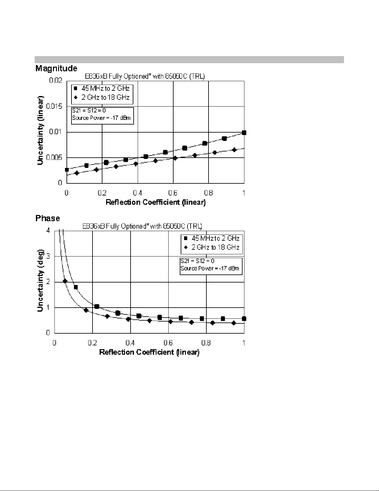
Reflection Uncertainty (Specifications)
*Configurable Test Set, Extended Power Range & Bias-Tees, Receiver Attenuators, Frequency Offset
Mode, and Reference Channel Transfer Switch (E836xB/C - Option 014, UNL, 016, 080, and 081)
56
Page 61

Table 19. 85050D Calibration Kit
Standard Configuration and Standard Power Range
(E836xB/C)
Applies to the, E836xB/C analyzers, 85050D (7mm) calibration kit, 85132F flexible test port cable set, and a full 2-port calibration. Also
applies to the following condition:
Environmental temperature 23° ±3 °C, with < 1 °C deviation from calibration temperature
Directivity 40 40
Source Match 39 35
Load Match 40 37
Reflection Tracking
Transmission Tracking
Specification (dB) Description
0.045 to
2 GHz
±0.010
+0.02/°C
±0.013
+0.02/°C
2 to
18 GHz
±0.100
+0.02/°C
±0.072
+0.02/°C
57
Page 62

NOTE: The following graphs also apply to the “C” model of the analyzers.
Transmission Uncertainty (Specifications)
58
Page 63

Reflection Uncertainty (Specifications)
59
Page 64

Table 20. 85050D Calibration Kit
Fully Optioned (E836xB/C - Option 014, UNL, 016, 080, and 081)
Configurable Test Set, Extended Power Range & Bias-Tees, Receiver Attenuators, Frequency Offset Mode, and Reference Channel
Transfer Switch
Applies to the, E836xB/C analyzers, 85050D (7mm) calibration kit, 85132F flexible test port cable set, and a full 2-port calibration. Also
applies to the following condition:
Environmental temperature 23° ±3 °C, with < 1 °C deviation from calibration temperature
Specification (dB) Description
0.045 to
2 GHz
2 to
18 GHz
Directivity 40 40
Source Match 39 35
Load Match 40 37
Reflection Tracking
Transmission Tracking
±0.010
+0.02/°C
±0.025
+0.02/°C
±0.100
+0.02/°C
±0.078
+0.02/°C
60
Page 65

NOTE: The following graphs also apply to the “C” model of the analyzers.
Transmission Uncertainty (Specifications)
*Configurable Test Set, Extended Power Range & Bias-Tees, Receiver Attenuators, Frequency Offset
Mode, and Reference Channel Transfer Switch (E836xB/C - Option 014, UNL, 016, 080, and 081)
61
Page 66

Reflection Uncertainty (Specifications)
*Configurable Test Set, Extended Power Range & Bias-Tees, Receiver Attenuators, Frequency Offset
Mode, and Reference Channel Transfer Switch (E836xB/C - Option 014, UNL, 016, 080, and 081)
62
Page 67

E836xB/C Corrected System Performance with Type-N Connectors
Table 21. 85054B Calibration Kit
Standard Configuration and Standard Power Range
(E836xB/C)
Applies to the, E836xB/C analyzers, 85054B (Type-N) calibration kit, 85132F flexible test port cable set with 85130C adapter set, and a full
2-port calibration. Also applies to the following condition:
Environmental temperature 23° ±3 °C, with < 1 °C deviation from calibration temperature
Specification (dB) Description
0.045 to
2 GHz
Directivity 48 42
Source Match 45 33
Load Match 48 41
Reflection Tracking
±0.001
+0.02/°C
Transmission Tracking
±0.006
+0.02/°C
2 to
18 GHz
±0.015
+0.02/°C
±0.079
+0.02/°C
63
Page 68

NOTE: The following graphs also apply to the “C” model of the analyzers.
Transmission Uncertainty (Specifications)
64
Page 69

Reflection Uncertainty (Specifications)
65
Page 70

Table 22. 85054B Calibration Kit
Fully Optioned (E836xB/C - Option 014, UNL, 016, 080, and 081)
Configurable Test Set, Extended Power Range & Bias-Tees, Receiver Attenuators, Frequency Offset Mode, and Reference Channel
Transfer Switch
Applies to the, E836xB/C analyzers, 85054B (Type-N) calibration kit, 85132F flexible test port cable set with 85130C adapter set, and a full
2-port calibration. Also applies to the following condition:
Environmental temperature 23° ±3 °C, with < 1 °C deviation from calibration temperature
Specification (dB) Description
0.045 to
2 GHz
2 to
18 GHz
Directivity 48 42
Source Match 45 33
Load Match 48 41
Reflection Tracking
Transmission Tracking
±0.001
+0.02/°C
±0.011
+0.02/°C
±0.015
+0.02/°C
±0.083
+0.02/°C
66
Page 71

NOTE: The following graphs also apply to the “C” model of the analyzers.
Transmission Uncertainty (Specifications)
* Configurable Test Set, Extended Power Range & Bias-Tees, Receiver Attenuators, Frequency Offset
Mode, and Reference Channel Transfer Switch
(E836xB/C - Option 014, UNL, 016, 080, and 081)
67
Page 72

Reflection Uncertainty (Specifications)
* Configurable Test Set, Extended Power Range & Bias-Tees, Receiver Attenuators, Frequency Offset
Mode, and Reference Channel Transfer Switch
(E836xB/C - Option 014, UNL, 016, 080, and 081)
68
Page 73

Table 23. 85054D Calibration Kit
Standard Configuration and Standard Power Range
(E836xB/C)
Applies to the, E836xB/C analyzers, 85054D (Type-N) calibration kit, 85132F flexible test port cable set with 85130C adapter set, and a full
2-port calibration. Also applies to the following condition:
Environmental temperature 23° ±3 °C, with < 1 °C deviation from calibration temperature
Specification (dB) Description
0.045 to
2 GHz
Directivity 40 34
Source Match 39 29
Load Match 40 34
Reflection Tracking
±0.003
+0.02/°C
Transmission Tracking
±0.013
+0.02/°C
2 to
18 GHz
±0.027
+0.02/°C
±0.136
+0.02/°C
69
Page 74

NOTE: The following graphs also apply to the “C” model of the analyzers.
Transmission Uncertainty (Specifications)
70
Page 75

Reflection Uncertainty (Specifications)
71
Page 76

Table 24. 85054D Calibration Kit
Fully Optioned (E836xB/C - Option 014, UNL, 016, 080, and 081)
Configurable Test Set, Extended Power Range & Bias-Tees, Receiver Attenuators, Frequency Offset Mode, and Reference Channel
Transfer Switch
Applies to the, E836xB/C analyzers, 85054D (Type-N) calibration kit, 85132F flexible test port cable set with 85130C adapter set, and a full
2-port calibration. Also applies to the following condition:
Environmental temperature 23° ±3 °C, with < 1 °C deviation from calibration temperature
Specification (dB) Description
0.045 to
2 GHz
2 to
18 GHz
Directivity 40 34
Source Match 39 29
Load Match 40 34
Reflection Tracking
Transmission Tracking
±0.003
+0.02/°C
±0.025
+0.02/°C
±0.027
+0.02/°C
±0.145
+0.02/°C
72
Page 77

NOTE: The following graphs also apply to the “C” model of the analyzers.
Transmission Uncertainty (Specifications)
* Configurable Test Set, Extended Power Range & Bias-Tees, Receiver Attenuators, Frequency Offset Mode,
and Reference Channel Transfer Switch
(E836xB/C - Option 014, UNL, 016, 080, and 081)
73
Page 78

Reflection Uncertainty (Specifications)
* Configurable Test Set, Extended Power Range & Bias-Tees, Receiver Attenuators, Frequency Offset Mode,
and Reference Channel Transfer Switch
(E836xB/C - Option 014, UNL, 016, 080, and 081)
74
Page 79

E8363B/C AND E8364B/C Corrected System Performance with WR-28 Connectors
Table 25. R11644A Calibration Kit
Standard Configuration and Standard Power Range
(E8363B/C AND E8364B/C)
Applies to the, E8363B/C AND E8364B/C analyzers, R11644A (WR-28) calibration kit, 85133F flexible test port cable set with the R281A
and R281B launch sets, and a full 2-port calibration. Also applies to the following condition:
Environmental temperature 23° ±3 °C, with < 1 °C deviation from calibration temperature
Description
Directivity 50
Source Match 50
Load Match 50
Reflection Tracking
Transmission Tracking
Specification (dB)
26.5 to
40 GHz
±0.000
+0.03/°C
±0.018
+0.03/°C
75
Page 80

NOTE: The following graphs also apply to the “C” model of the analyzers.
Transmission Uncertainty (Specifications)
76
Page 81

Reflection Uncertainty (Specifications)
77
Page 82

Table 26. R11644A Calibration Kit
Fully Optioned (E836xB/C - Option 014, UNL, 016, 080, and 081)
Configurable Test Set, Extended Power Range & Bias-Tees, Receiver Attenuators, Frequency Offset Mode, and Reference Channel
Transfer Switch
Applies to the, E8363B/C AND E8364B/C analyzers, R11644A (WR-28) calibration kit, 85133F flexible test port cable set with the R281A
and R281B launch sets, and a full 2-port calibration. Also applies to the following condition:
Environmental temperature 23° ±3 °C, with < 1 °C deviation from calibration temperature
Description
Specification (dB)
26.5 to
40 GHz
Directivity 50
Source Match 50
Load Match 50
Reflection Tracking
±0.000
+0.03/°C
Transmission Tracking
±0.019
+0.03/°C
78
Page 83

NOTE: The following graphs also apply to the “C” model of the analyzers.
Transmission Uncertainty (Specifications)
* Configurable Test Set, Extended Power Range & Bias-Tees, Receiver Attenuators, Frequency Offset
Mode, and Reference Channel Transfer Switch (E836xB/C - Option 014, UNL, 016, 080, and 081)
79
Page 84

Reflection Uncertainty (Specifications)
* Configurable Test Set, Extended Power Range & Bias-Tees, Receiver Attenuators, Frequency Offset
Mode, and Reference Channel Transfer Switch (E836xB/C - Option 014, UNL, 016, 080, and 081)
80
Page 85

E8363B/C AND E8364B/C Corrected System Performance with WR-42 Connectors
Table 27. K11644A Calibration Kit
Standard Configuration and Standard Power Range
(E8363B/C AND E8364B/C)
Applies to the, E8363B/C AND E8364B/C analyzers, K11644A (WR-42) calibration kit, 85134F flexible test port cable set with the K281C
launch set,
Environmental temperature 23° ±3 °C, with < 1 °C deviation from calibration temperature
Directivity 50 50
Source Match 50 50
Load Match 50 50
Reflection Tracking
Transmission Tracking
, and a full 2-port calibration. Also applies to the following condition:
Specification (dB) Description
18 to
20 GHz
±0.000
+0.02/°C
±0.014
+0.02/°C
20 to
26.5 GHz
±0.000
+0.02/°C
±0.018
+0.02/°C
81
Page 86

NOTE: The following graphs also apply to the “C” model of the analyzers.
Transmission Uncertainty (Specifications)
82
Page 87

Reflection Uncertainty (Specifications)
83
Page 88

Table 28. K11644A Calibration Kit
Fully Optioned (E836xB/C - Option 014, UNL, 016, 080, and 081)
Configurable Test Set, Extended Power Range & Bias-Tees, Receiver Attenuators, Frequency Offset Mode, and Reference Channel
Transfer Switch
Applies to the, E8363B/C AND E8364B/C analyzers, K11644A (WR-42) calibration kit, 85134F flexible test port cable set with the K281C
launch set,, and a full 2-port calibration. Also applies to the following condition:
Environmental temperature 23° ±3 °C, with < 1 °C deviation from calibration temperature
Specification (dB) Description
18 to
20 GHz
20 to
26.5 GHz
Directivity 50 50
Source Match 50 50
Load Match 50 50
Reflection Tracking
Transmission Tracking
±0.000
+0.02/°C
±0.016
+0.02/°C
±0.000
+0.02/°C
±0.019
+0.02/°C
84
Page 89

NOTE: The following graphs also apply to the “C” model of the analyzers.
Transmission Uncertainty (Specifications)
* Configurable Test Set, Extended Power Range & Bias-Tees, Receiver Attenuators, Frequency Offset
Mode, and Reference Channel Transfer Switch (E836xB/C - Option 014, UNL, 016, 080, and 081)
85
Page 90

Reflection Uncertainty (Specifications)
* Configurable Test Set, Extended Power Range & Bias-Tees, Receiver Attenuators, Frequency Offset
Mode, and Reference Channel Transfer Switch (E836xB/C - Option 014, UNL, 016, 080, and 081)
86
Page 91

E836xB/C Corrected System Performance with WR-62 Connectors
Table 29. P11644A Calibration Kit
Standard Configuration and Standard Power Range
(E836xB/C)
Applies to the, E836xB/C analyzers, P11644A (WR-62) calibration kit, 85132F flexible test port cable set with the P281B and P281C
launch sets, and a full 2-port calibration. Also applies to the following condition:
Environmental temperature 23° ±3 °C, with < 1 °C deviation from calibration temperature
Description
Directivity 50
Source Match 50
Load Match 50
Reflection Tracking
Transmission Tracking
Specification (dB)
12.4 to
18 GHz
±0.000
+0.02/°C
±0.014
+0.02/°C
87
Page 92

NOTE: The following graphs also apply to the “C” model of the analyzers.
Transmission Uncertainty (Specifications)
88
Page 93

Reflection Uncertainty (Specifications)
89
Page 94

Table 30. P11644A Calibration Kit
Fully Optioned (E836xB/C - Option 014, UNL, 016, 080, and 081)
Configurable Test Set, Extended Power Range & Bias-Tees, Receiver Attenuators, Frequency Offset Mode, and Reference Channel
Transfer Switch
Applies to the, E836xB/C analyzers, P11644A (WR-62) calibration kit, 85132F flexible test port cable set with the P281B and P281C launch
sets, and a full 2-port calibration. Also applies to the following condition:
Environmental temperature 23° ±3 °C, with < 1 °C deviation from calibration temperature
Description
Specification (dB)
12.4 to
18 GHz
Directivity 50
Source Match 50
Load Match 50
Reflection Tracking
±0.000
+0.02/°C
Transmission Tracking
±0.016
+0.02/°C
90
Page 95

NOTE: The following graphs also apply to the “C” model of the analyzers.
Transmission Uncertainty (Specifications)
* Configurable Test Set, Extended Power Range & Bias-Tees, Receiver Attenuators, Frequency Offset
Mode, and Reference Channel Transfer Switch (E836xB/C - Option 014, UNL, 016, 080, and 081)
91
Page 96

Reflection Uncertainty (Specifications)
* Configurable Test Set, Extended Power Range & Bias-Tees, Receiver Attenuators, Frequency Offset
Mode, and Reference Channel Transfer Switch (E836xB/C - Option 014, UNL, 016, 080, and 081)
92
Page 97

E836xB/C Corrected System Performance with WR-90 Connectors
Table 31. X11644A Calibration Kit
Standard Configuration and Standard Power Range
(E836xB/C)
Applies to the, E836xB/C analyzers, X11644A (WR-90) calibration kit, 85133F flexible test port cable set with the X281A and X281C launch
sets, and a full 2-port calibration. Also applies to the following condition:
Environmental temperature 23° ±3 °C, with < 1 °C deviation from calibration temperature
Specification (dB) Description
8.2 to
12.4 GHz
Directivity 50
Source Match 50
Load Match 50
Reflection Tracking
Transmission Tracking
±0.000
+0.02/°C
±0.014
+0.02/°C
93
Page 98

NOTE: The following graphs also apply to the “C” model of the analyzers.
Transmission Uncertainty (Specifications)
94
Page 99

Reflection Uncertainty (Specifications)
95
Page 100
Table 32. X11644A Calibration Kit
Fully Optioned (E836xB/C - Option 014, UNL, 016, 080, and 081)
Configurable Test Set, Extended Power Range & Bias-Tees, Receiver Attenuators, Frequency Offset Mode, and Reference Channel
Transfer Switch
Applies to the, E836xB/C analyzers, X11644A (WR-90) calibration kit, 85133F flexible test port cable set with the X281A and X281C launch
sets, and a full 2-port calibration. Also applies to the following condition:
Environmental temperature 23° ±3 °C, with < 1 °C deviation from calibration temperature
Specification (dB) Description
8.2 to
12.4 GHz
Directivity 50
Source Match 50
Load Match 50
Reflection Tracking
Transmission Tracking
±0.000
+0.02/°C
±0.016
+0.02/°C
96
 Loading...