

Page 1

Agilent
PNA Series
Microwave Network Analyzers
Configuration Guide
PNA E8362C 10 MHz to 20 GHz
PNA E8363C 10 MHz to 40 GHz
PNA E8364C 10 MHz to 50 GHz
PNA E8361C 10 MHz to 67 GHz
This guide describes standard configurations,
for the PNA (E836xC) Series microwave network
analyzers. This guide should be used with the
Agilent PNA family data sheets for a complete
description of these analyzers.
For applications, measurement accessories, and
general accessories please see Agilent PNA Family
Network Analyzers Configuration Guide, part number
5990-7745EN.
Page 2

Agilent offers the following options for all PNA family network analyzers
Certification options
□ Commercial calibration certification with test data (Option UK6)
Complete set of measurements which tests unit to manufacturer’s
published specifications. Includes calibration label, calibration
certificate, and data report. Conforms to ISO 9001.
□ ISO 17025 compliant calibration (Option 1A7)
Complete set of measurements which tests unit to manufacturer’s
published specifications. Includes calibration label, ISO 17025
calibration certificate, and data report, measurement uncertainties
and guardbands on all customer specifications. Conforms to ISO
17025 and ISO 9001.
□ ANSI Z540 compliant calibration (Option A6J)
Complete set of measurements which tests unit to manufacturer’s
published specifications. Includes pre- and post-adjustment data
with measurement uncertainty information compliant to the
ANSI/NCSL Z540 standard.
Warranty and service
1-, 3-, and 5-year warranty and service plans are available at the
time of instrument purchase. Standard warranty is 1 year.
Documentation
The PNA Series instruments are equipped with an Online Help
system available within the instrument in the following languages:
English, Japanese, Chinese, German, Spanish, and French. Service
guides and the Online Help system are available on the web:
www.na.tm.agilent.com/pna
Calibration Software Licenses
□ Perpetual license for built-in performance test software for
Agilent inclusive cal (Option 897)
Adds built-in performance testing and calibration software for
self-maintainers. Requires additional equipment. See the analyzer’s
Service Guide for more information on equipment required.
□ Perpetual license for built-in performance test software for
Standards compliant cal (Option 898)
Adds built-in performance testing and calibration software for
self-maintainers. Requires additional equipment. See the analyzer’s
Service Guide for more information on equipment required.
2
Page 3

PNA Series Network Analyzer
E8362C 10 MHz to 20 GHz E8363C 10 MHz to 40 GHz E8364C 10 MHz to 50 GHz E8361C 10 MHz to 67 GHz
Option configurations
To add options to a product, order the corresponding item number.
Description For E8362C For E8363C For E8364C For E8361C Additional
information
Test set
Option 014 Configurable test set E8362C-014 E8363C-014 E8364C-014 E8361C-014
Power configuration
Option UNL Extended power range E8362C-UNL E8363C-UNL E8364C-UNL E8361C-UNL Only E8361C requires 014
and bias-tees
Option 016 Add receiver attenuators E8362C-016 E8363C-016 E8364C-016 E8361C-016 Requires UNL (only E8361C also
Option H851 High-power configuration E8362CH85 E8363CH85 E8364CH85 Includes 014, 016, UNL2, 080, 081
Measurement applications
Option 010 Time-domain capability E8362C-010 E8363C-010 E8364C-010 E8361C-010
Option 080 Frequency offset E8362C-080 E8363C-080 E8364C-080 E8361C-080 Requires 014 (E8361C only, 081 required
if UNL is also purchased)
Option 081 Reference receiver switch E8362C-081 E8363C-081 E8364C-081
requires UNL)
Option 082 Scalar-calibrated E8362C-082 E8363C-082 E8364C-082 E8361C-082 Requires 014, 080
converter measurements
Option 083 Vector- and scalar-calibrated E8362C-083 E8363C-083 E8364C-083 E8361C-083 Requires 014, 080, 081(only E8361C
converter measurements also requires UNL)
Option 084
Option 550
Option 551
Pulse, antenna, mm-wave
Option H08 Pulsed-RF measurement E8362C-H08 E8363C-H08 E8364C-H08 E8361C-H08 Requires 014, 080 (Option H11
capabili ty recommended)
Option H11
pulsed-RF and mm-wave
measurements)
Accessories
Option 1CM Rack mount kit for use E8362C-1CM E8363C-1CM E8364C-1CM E8361C-1CM
without handles
Option 1CP Rack mount kit for use E8362C-1CP E8363C-1CP E8364C-1CP E8361C-1CP
with handles
Calibration documentation
Option 1A7 ISO 17025 compliant E8362C-1A7 E8363C-1A7 E8364C-1A7 E8361C-1A7
calibration
Option UK6 Commercial calibration E8362C-UK6 E8363C-UK6 E8364C-UK6 E8361C-UK6
certificate with test data
Option A6J ANSI Z540 compliant E8362C-A6J E8363C-A6J E8364C-A6J E8361C-A6J
calibration
Calibration software for self-maintainers
Option 897
performance test software for Agilent exclusive calibration
Option 8985
performance test software for standards compliant calibration
requires 014)
E8361C-081
3
Embedded LO measurements E8362C-084 E8363C-084 E8364C-084 E8361C-084 Requires 082 or 083
4
4-port measurement application
4
N-port capabilities E8362C-551 E8363C-551 E8364C-551 E8361C-551 Requires 014
IF access (for antenna, E8362C-H11 E8363C-H11 E8364C-H11 E8361C-H11 Requires 014, UNL, 080, and 081
5
Perpetual license of built-in
Perpetual license of built-in
E8362C-550 E8363C-550 E8364C-550 E8361C-550 Requires 014
E8362C-897 E8363C-897 E8364C-897 E8361C-897
E8362C-898 E8363C-898 E8364C-898 E8361C-898
Requires 014, 080 (only E8361C also
1. Option H85 is ordered as a separate model, as indicated.
2. UNL up to 67 GHz does not include bias-tees. Only includes source attenuators.
3. Requires firmware A.07.05 and above, plus 1.1 GHz CPU board.
4. Option 550 is a subset of 551; therefore they cannot be ordered together. When ordering a test set, select an option to specify the appropriate
interconnect jumper cable set between the analyzer and the test set.
5. Additional hardware required. Please refer to the analyzer’s Service Guide for required service test equipment.
3
Page 4

PNA Series Network Analyzer
The microwave PNA Series instruments are integrated vector
network analyzers equipped with a built-in S-parameter test set,
synthesized source, a hard disk drive, USB interfaces, and an
8.4” LCD color touch screen display. The E8362C has 3.5 mm
male 50-ohm test ports. The E8363C/64C have 2.4 mm male
50-ohm test ports. The E8361C has 1.85 mm male 50-ohm test
ports. Included with each instrument is a mouse, keyboard (U.S.)
and a 1-year return-to-Agilent service warranty.
Test set and power configuration options
□ Configurable test set (Option 014)
Provides six front panel access loops. Three access loops are
for port one and three for port two. The loops provide access
to the signal path between (a) the source output and the
reference receiver, (b) the source output and directional coupler
thru arm and (c) the coupled arm of the directional coupler and
the port receiver. This option provides the capability to improve
instrument sensitivity for measuring low-level signals, to
reverse the directional coupler to achieve even more dynamic
range or to add components and other peripheral instruments
for a variety of measurement applications. (see PNA Series
Microwave Data Sheet literature number 5989-7605EN for a
basic block diagram)
□ Extended power range and bias-tees (Option UNL)
Adds two 60 dB step attenuators and two bias-tees to the
E8362/3/4C. Adds two 50 dB step attenuators and two bias-tees
to the E8361C. A step attenuator and bias-tee set is inserted
between the source and test port one and another set
between the source and test port two. (see PNA Series
Microwave Data Sheet literature number 5989-7605EN for a
basic block diagram)
□ Add receiver attenuators (Option 016)
An attenuator is added between each test port and its
corresponding receiver. Two 35 dB step attenuators are added
to the E8362/3/4C. Two 50 dB step attenuators are added to
the E8361C (see PNA Series Microwave Data Sheet literature
number 5989-7605EN for a basic block diagram).
□ High-power test set (Model E836xCH85)
This configuration combines options that are often necessary
for high power measurements (UNL1, 014, 016, 080, 081).
The only difference between ordering Option H85 versus a
combination of the options listed above is the source
attenuator option UNL. Standard UNL includes two source
attenuators and two bias-tees. Option H85 includes the two
source attenuators, but not the bias-tees, as the bias-tees are
the power-limiting factor in the network analyzer test set. The
maximum power at the test port is +43 dBm (< 20 GHz), and
+40 dBm (> 20 GHz).
Option 080, frequency-offset mode, is included in Option H85
because it manages the phase-locking internally (instead of
depending on the R1 receiver). So if you need to use external
components in the path of the R1 receiver, it makes the
measurements simpler and more robust.
Measurement applications
□ Time-domain capability (Option 010)
For viewing reflection and transmission responses in time or
distance domain.
□ Frequency offset (Option 080)
This option enables the PNA Series microwave network analyzers
to set the source frequency independently from where the
receivers are tuned. This ability is important for two general
classes of devices: mixers (and converters) and amplifiers.
Option 080 provides a very basic user interface.
□ Reference receiver switch (Option 081)
Option 081 adds a solid-state internal RF transfer switch in the
R1 reference-receiver path (see PNA Series Microwave Data
Sheet literature number 5989-7605EN for a block diagram). The
switch allows the instrument to easily switch between standard
S-parameter (non-frequency-offset) measurements and frequency
offset measurements such as relative phase or absolute group
delay that require an external reference mixer. The user can set
the switch manually or remotely, but it is best used with the
frequency-converter application (Option 083), where it is controlled
automatically during the vector-mixer calibration procedure
and subsequent measurements.
□ Scalar-calibrated converter measurements (Option 082)
With a simple setup and calibration, this application provides
the highest accuracy for conversion-loss (or gain) measurements
by combining one-port and power-meter calibrations to remove
mismatch errors. Option 080 required.
□ Vector- and scalar-calibrated converter measurements
(Option 083)
This converter measurement adds an intuitive and easy-to-use
user interface, advanced calibration choices that provide
exceptional amplitude and phase accuracy, and control of
external signal sources for use as local oscillators. Mixer
calibration techniques include scalar-mixer calibration and
vector-mixer calibration (requires Option 081). Finally, the
frequency-converter application supports all of Agilent’s major
signal source families.
□ Embedded LO Measurements (Option 084)
This option tunes the PNA receivers to the output frequency of
the converter under test, without the need for access to internal
LOs or a common reference signal. For converters with embed ded LOs, this option enables measurements of match-corrected
conversion loss/gain (requires Option 082 or 083), and absolute
group delay (requires Option 083).
1. UNL does not include bias-tees. Only includes source attenuators
4
Page 5

PNA Series Network Analyzer
□ 4-port measurement application (Option 550)
Adds multiport analyzer mode to any PNA network analyzer
with Option 014 configurable test set, which enables full
4-port error correction and measurement capabilities using an
external test set. Only standard measurement class is available
in the multiport analyzer mode.
□ N-port capabilities (Option 551)
Adds multiport analyzer mode to any PNA network analyzer
with Option 014 configurable test set, which enables full
N-port error correction and measurement capabilities using
an external test set. Only standard measurement class is
available in the multiport analyzer mode.
Pulse, antenna, mm-wave
□ Pulsed-RF measurement capability (Option H08)
Provides software to set up and control pulsed-RF measurements
with point-in-pulse capability. The software sets the coefficient
of the PNA’s digital-IF filter to null out unwanted spectral
components, enables the IF gates provided with IF access
(Option H11), and controls selected Agilent pulse generators.
It can be run on the PNA or an external computer. A “.dll” file
containing the IF-filter algorithms is included for automated
pulsed-RF testing. The pulsed application is configured to work
with the Agilent 81110A series pulse generator.
For more detailed information regarding pulsed measurement
capabilities with the microwave PNA refer to the Agilent Web
site www.agilent.com/find/pna and download the PNA Series
MW Network Analyzers Configuration Guide for Pulsed
Measurements, literature number 5989-7913EN.
□ IF access (Option H11)
Provides hardware to enable antenna, point-in pulse, and
broadband millimeter-wave measurements to 110 GHz. For
each of the MW PNA’s measurement receivers, IF gates
(enabled with pulsed measurement capability, Option H08) and
external IF inputs are added. In addition, access to the PNA’s
internal RF and LO source is provided for remote mixing
applications. For basic antenna measurements, only Option H11
is necessary. Pulsed antenna applications also require the
pulsed measurement capability (Option H08). Broadband
measurements to 110 GHz, also requires an N5260A
millimeter-wave test set controller.
Accessories
□ Rack mount kit without handles (Option 1CM)
Adds a rack mount (5063-9217) and rail kit (E3663AC) for use
without handles.
□ Rack mount kit with handles (Option 1CP)
Adds a rack mount (5063-9237)1 and rail kit (E3663AC) for use
with standard supplied handles.
Configuration Details
Selecting the correct mixer-test configuration:
Most mixer or converter test applications require Options 014, 080,
and 082 for conversion loss/gain, or Options 014, 080, 081 and
083 for conversion loss/gain and phase/delay measurements. If
you want to create and automate your own custom frequencyoffset measurements (for example, intermodulation distortion),
you may only need Options 014 and 080. For converters that
require input power below -27 dBm, or for devices that have a
large amount of LO feedthrough (like an unfiltered mixer), Option
UNL, which adds source attenuators, is highly recommended.
Besides allowing lower input power levels, these attenuators
improve the isolation between the PNA’s internal source and
LO leakage signals, helping to prevent source-unleveled errors.
For devices that put out signals near or above the receiver’s
compression levels (which varies between –3 and +5 dBm,
depending on the model and frequency), Option 016 is recommended, which adds receiver attenuators. Finally, Option 010,
which adds time-domain analysis, is very useful for gating out
unwanted, time-delayed responses which often occur when
measuring mixers.
Note: Use external IF access for up to 20 dB more sensitivity
when making antenna measurements with a remote mixing
configuration. Add Option H08 (Pulsed-RF Measurement
Capability) to enable advanced pulsed measurements. Or
upgrade to a broadband (10 MHz to 110 GHz) VNA system
simply by purchasing an N5260A controller test set with test
heads (Option 110, 120, or 130).
1. The 5063-9237 kit assumes you have the standard handles shipped
with the instrument. If you do not have handles, order a 5063-9224 kit.
5
Page 6
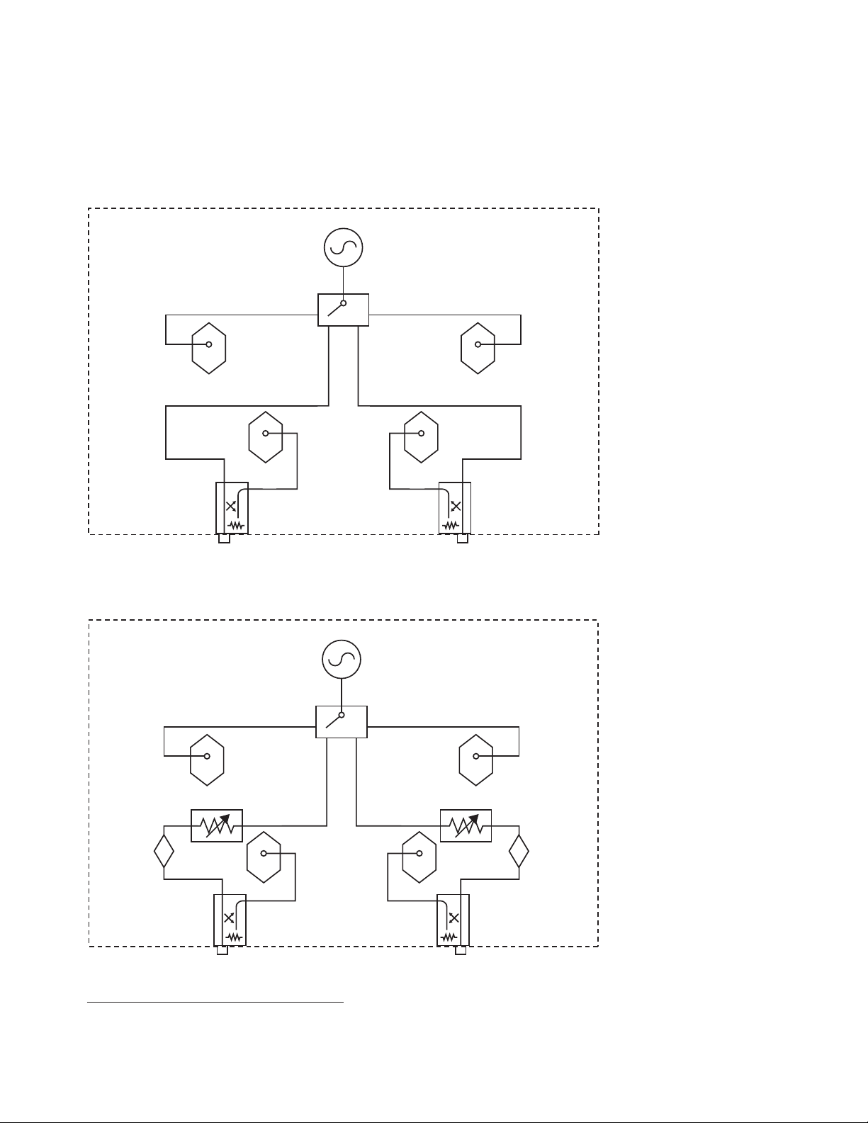
PNA Series Network Analyzer
Source
Switch/splitter
Reference
receiver
Reference
receiver
Measurement
receivers
Port 1 Port 2
A
B
R1 R2
Source
Switch
Reference
receiver
Reference
receiver
Measurement
receivers
Port 1 Port 2
A
B
R1 R2
Source attenuator
1
Source attenuator
1
Bias-teeBias-tee
Simplified test set block diagrams
Standard power range
Extended power range and bias-tees (Option UNL)
1. Source attenuator for E8362/3/4C is 60 dB in 10 dB steps.
Source attenuator for E8361C is 50 dB in 10 dB steps.
6
Page 7
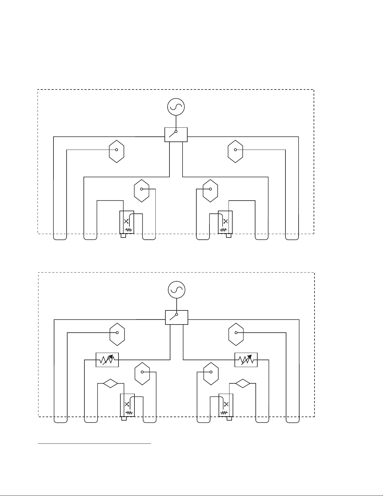
PNA Series Network Analyzer
Source
Switch
Reference
receiver
Reference
receiver
Measurement
receivers
Port 1 Port 2
A
B
R1 R2
Source
Switch
Reference
receiver
Reference
receiver
Measurement
receivers
Port 1 Port 2
Bias-tee
Source attenuator
1
A
Bias-tee
Source attenuator
1
B
R1 R2
Simplified test set block diagrams – continued
Configurable test set (Option 014)
Configurable test set with extended power range and bias-tees (Option UNL and 014)
1. Source attenuator for E8362/3/4C is 60 dB in 10 dB steps.
Source attenuator for E8361C is 50 dB in 10 dB steps.
7
Page 8

PNA Series Network Analyzer
Source
Switch/splitter/leveler
Reference
receiver
Reference
receiver
Measurement
receivers
Cplr
arm
Bias-tee
Source attenuator
1
A
Bias-tee
Source attenuator
1
B
R1 R2
10 dB steps
10 dB steps
Receiver
attenuator
2
Rcvr B
in
Rcvr A
in
Cplr
arm
SRC
out
Cplr
thru
Source
out
Rcvr R2
in
Cplr
thru
SRC
out
Rcvr R1
in
Source
out
Option 081
Simplified test set block diagrams – continued
Fully optioned, active device or mixer/converter test configuration (Options 014, UNL, 016, 080, 081)
1. Source attenuator for E8362/3/4C is 60 dB in 10 dB steps. Source attenuator for
E8361C is 50 dB in 10 dB steps.
2. Receiver attenuator for E8362/3/4C is 35 dB in 5 dB steps. Receiver attenuator for
E8361C is 50 dB in 10 dB steps.
8
Page 9

PNA Series Network Analyzer
Source
Switch/splitter/leveler
Reference
receiver
Reference
receiver
Measurement
receivers
Cplr
arm
A B
R1 R2
10 dB steps
10 dB steps
Receiver
attenuator
2
Rcvr B
in
Rcvr A
in
Cplr
arm
SRC
out
Cplr
thru
Source
out
Rcvr R2
in
Cplr
thru
SRC
out
Rcvr R1
in
Source
out
Option 081
D
U
T
+40
dBm
+30
dBm
+15
dBm
+30
dBm
+30
dBm
+15
dBm
+15
dBm
+40
dBm
+15
dBm
preamp
Source attenuator
1
Source attenuator
1
+30
dBm
+30
dBm
Simplified test set block diagrams – continued
High-power configuration (Model E836xCH85)
Power levels shown on the diagram are damage levels. At a minimum, keep power levels 6 dB below damage level. For optimal
performance, keep the power level incident upon the receivers -20 dBm or less. This will keep the receivers out of compression.
1. Source attenuator for E8362/3/4C is 60 dB in 10 dB steps.
2. Receiver attenuator for E8362/3/4C is 35 dB in 5 dB steps.
9
Page 10

PNA Series Network Analyzer
Option 016
Receiver
attenuators
Port 1 Port 2
Option UNL
Option UNL
Option UNL
Option UNL
IF gate
ADC
External
IF in
Option H11
1
R2
ADC
External
IF in
Option H11
1
B
ADC
External
IF in
Option H11
1
R1
IF gate
ADC
External
IF in
Option H11
1
A
LO
Option H11
Multipliers
(1, 2)
Multipliers (1, 2, 4)
YIG source
8.33 MHz
reference
Offset
LO
Phase-locked loop
V
tune
Option 080
Option 081
Option 014Option 014
Option 014
Front
Rear
Aux RF out
(2 to 20 GHz)
Aux LO out
(2 to 20 GHz)
Offset receiver
IF gate
IF gate
Simplified test set block diagrams – continued
Fully optioned, pulse-RF, antenna, or mm-wave configuration
(Options 014, UNL, 016, 080, 081, H11)
1. Option H11: IF-gate controls and external-IF inputs are accessed on rear panel.
IF gates are enabled with Option H08. External-IF input frequency is 8.33 MHz.
10
Page 11

PNA Series Network Analyzer
Upgrade kits
Upgrade kits for the PNA Series E8361C, E8362C, E8363C,
E8364C
Upgrade kits are available to add options after initial purchase. To
order an upgrade kit for the PNA series, order the analyzer’s model
number followed by a “U”, then indicate the option to be added
(for example, E8362CU-010). The current configuration and serial
number of the instrument to be retrofitted are required as part of
the order.
□ Time-domain (Option 010)
User installable.
□ Configurable test set (Option 014)
Provides six front-panel RF access loops.
Includes installation at an Agilent service center.
□ Receiver attenuators (Option 016)
Includes installation at an Agilent service center.
□ Frequency range upgrade to an E8363C (40 GHz) PNA
(Option 040/041)
Available only for the E8362C. Includes
installation at an Agilent service center.
□ Frequency range upgrade to an E8364C (50 GHz) PNA
(Option 050/051)
Available only for the E8362C and E8363C.
Includes installation at an Agilent service center.
□ Frequency range upgrade to an E8361C (67 GHz) PNA
(Option 067/068)
Available only for the E8363C and E8364C.
Includes installation at an Agilent service center.
□ Frequency-offset (Option 080)
Includes installation at an Agilent service center.
□ External reference switch (Option 081)
Includes installation at an Agilent service center.
□ Scalar-calibrated converter measurements (Option 082)
User installable. Option 080 required.
□ Frequency converter measurement application (Option 083)
User installable. Option 080 and 081 required.
□ Embedded LO Measurements (Option 084)
Advanced software tuning that provides absolute group delay of
converters with embedded LOs without the need for access to a
common reference signal. The measurement result is the same as
locking the DUT LO to the reference mixer LO. (Options 080
and 083 required) Requires firmware A.07.05 and above plus
1.1 GHz CPU board.
□ A/B to C model upgrades
Order E8361AU-221, E8362BU-221, E8363BU-221, or E8364BU-221
Note:
1.1 GHz CPU is required to upgrade. Please refer to Customer Support Service
Guides for the correct part number http://na.tm.agilent.com/pna/documents.html
□ 4-Port measurement application (Option 550)
(Available for E8361C, E8362C/3C/4C)
Enables full 4-port error correction and differential
measurements. Option 014 and external test set required.
User installable.
□ N-port capabilities (Option 551)
(Available for E8361C, E8362C/3C/4C)
Adds full N-port error correction and measurement
capabilities. Option 014 and external test set required.
User installable.
□ Extended power range (Option UNL)
Adds a step attenuator and a bias-tee between source and
each test port. Includes installation at an Agilent service center.
□ Pulsed-RF measurement capability (Option H08)
Provides software to set up and control pulsed-RF
measurements using narrowband detection, with point-in-pulse
and pulse-profile capability. User installable.
□ IF access (Option H11)
Provides hardware for antenna, point-in-pulse, and millimeter wave measurements. Adds rear-panel RF and LO outputs,
external IF inputs, and IF gates (gates enabled with Option H08).
Includes installation at an Agilent service center.
□ High-power test set (Option H85)
Removes bias tees for higher test port power-handling capability.
Options UNL, 014, 016, 080, and 081 are required. Includes
installation at an Agilent Service Center.
Calibration Software Licenses
□ Perpetual license for built-in performance test software
for Agilent inclusive cal (Option 897)
Adds built-in performance testing and calibration software
for self-maintainers. Requires additional equipment. See
the analyzer’s Service Guide for more information on
equipment required.
□ Perpetual license for built-in performance test software
for standards compliant cal (Option 898)
Adds built-in performance testing and calibration software
for self-maintainers. Requires additional equipment. See
the analyzer’s Service Guide for more information on
equipment required.
Note: For applications, measurement accessories, and general
accessories please see Agilent PNA Family Network Analyzers
Configuration Guide, part number 5990-7745EN.
11
Page 12

www.agilent.com
www.agilent.com/find/pna
Agilent Email Updates
www.agilent.com/find/emailupdates
Get the latest information on the
products and applications you select.
www.lxistandard.org
LAN eXtensions for Instruments puts
the power of Ethernet and the Web
inside your test systems. Agilent
is a founding member of the LXI
consortium.
Agilent Channel Partners
www.agilent.com/find/channelpartners
Get the best of both worlds: Agilent’s
measurement expertise and product
breadth, combined with channel
partner convenience.
Expand your measurement
capabilities with Agilent
qualified channel partners
Our channel partners offer accessories
and measurement solutions that extend
your network analysis capabilities.
For more information about probing
equipment and accessories, contact:
Cascade Microtech, Inc
2430 NW 206th Avenue
Beaverton, Oregon 97006, USA
Toll free telephone: 1-800-550-3279
Telephone: (503) 601-1000
Fax: (503) 601-1002
Web site: www.cascademicrotech.com
E-mail: sales@cmicro.com
Agilent Advantage Services is committed
to your success throughout your equipment’s lifetime. To keep you competitive,
we continually invest in tools and
processes that speed up calibration and
repair and reduce your cost of ownership.
You can also use Infoline Web Services
to manage equipment and services more
effectively. By sharing our measurement
and service expertise, we help you create
the products that change our world.
www.agilent.com/find/advantageservices
www.agilent.com/quality
For more information on Agilent Technologies’
products, applications or services, please
contact your local Agilent office. The
complete list is available at:
www.agilent.com/find/contactus
Americas
Canada (877) 894 4414
Brazil (11) 4197 3500
Mexico 01800 5064 800
United States (800) 829 4444
Asia Pacific
Australia 1 800 629 485
China 800 810 0189
Hong Kong 800 938 693
India 1 800 112 929
Japan 0120 (421) 345
Korea 080 769 0800
Malaysia 1 800 888 848
Singapore 1 800 375 8100
Taiwan 0800 047 866
Other AP Countries (65) 375 8100
Europe & Middle East
Belgium 32 (0) 2 404 93 40
Denmark 45 70 13 15 15
Finland 358 (0) 10 855 2100
France 0825 010 700*
*0.125 €/minute
Germany 49 (0) 7031 464 6333
Ireland 1890 924 204
Israel 972-3-9288-504/544
Italy 39 02 92 60 8484
Netherlands 31 (0) 20 547 2111
Spain 34 (91) 631 3300
Sweden 0200-88 22 55
United Kingdom 44 (0) 131 452 0200
For other unlisted countries:
www.agilent.com/find/contactus
Revised: June 8, 2011
Product specifications and descriptions
in this document subject to change
without notice.
© Agilent Technologies, Inc. 2009-2011
Published in USA, July 26, 2011
5989-7606EN
Pentium® is a U.S. registered trademark of Intel Corporation.
Microsoft® and Windows® are registered trademarks of Microsoft Corporation.
12
 Loading...