


User Manual: CA2 Preamplifier
Amplifiers |
SCA2 Preamplifier |
|
SIA2-150 Integrated Amplifier |
||
SPA2-150 Power Amplifier |
||
|
||
|
SPA2-200P Power Amplifier |
|
|
|
MULTICHANNEL
®
A C O U S T I C E N G I N E E R S

S a f e t y W a r n i n g s
Electronics
1.Read instructions – all the safety and operating instructions should be read before the appliance is operated.
2.Retain these instructions – the safety and operating instructions should be retained for future reference.
3.Heed warnings – all warnings on the appliance and in the operating instructions should be adhered to.
4.Follow instructions – all operating and other instructions should be followed.
5.Water and moisture – the appliance should not be used near water, for example near a bathtub, washbowl, kitchen sink, laundry tub, in a wet basement or near a swimming pool etc..
6.Ventilation – the appliance should be situated so that its location or position does not interfere with its proper ventilation. For example, the appliance should not be situated on a bed, sofa, rug or similar surface that may block the ventilation openings. Similarly, the appliance should not be built into an installation, such as a bookcase or cabinet, that may impede the flow of air through the ventilation openings.
7.Heat – the appliance should be situated away from heat sources such as radiators, stoves or other appliances that produce heat.
8.Power sources – the appliance should be connected to a power supply only of the type described in the operating instructions or as marked on the appliance.
9.Power cord protection – power supply cords should be routed so that they are not likely to be walked on or pinched by items placed upon or against them, paying particular attention to cords at plugs, convenience receptacles and the point where they exit the appliance.
10.Cleaning – the appliance should be cleaned only as recommended by the manufacturer.
11.Unattended periods – the power cord of the appliance should be unplugged from the outlet when left unused for a long period of time.
12.Object and liquid entry – care should be taken so that objects and liquids do not fall into the appliance.
13.Damage requiring service – the appliance should be serviced by qualified service personnel when:
i.the power supply cord or the plug has been damaged
ii.objects have fallen or liquid has been spilled into the appliance
iii.the appliance has been exposed to rain or other serious liquid exposure
iv.the appliance does not appear to operate normally or exhibits a marked change in performance
v.the appliance has been dropped or the cabinet damaged
14.Servicing – the user should not attempt to service the appliance beyond those measures described in the operating instructions.All other servicing should be referred to qualified service personnel.
15.Grounding or polarisation – precautions should be taken so that grounding or polarisation means for the appliance are not defeated.
1

Electronics
I n t r o d u c t i o n
C o n t e n t s
Page 2 |
|
Introduction |
Page 3 |
CA2 Preamplifier |
|
|
Section 1.1 |
Description |
|
Section 1.2 |
Installation |
|
Section 1.3 |
Mains Connection |
Page 4 |
Section 1.4 |
Inputs |
Page 5 |
Section 1.5 |
Outputs |
|
Section 1.6 |
Operation |
Page 6 |
Section 1.7 |
Remote Handset |
|
Section 1.8 |
Care and Maintenance |
|
Section 1.9 |
Warranty and Contact |
|
|
Specifications |
Page 7 |
SCA2 Preamplifier |
|
|
Section 2.1 |
Description |
|
Section 2.2 |
Installation |
|
Section 2.3 |
Mains Connection |
Page 8 |
Section 2.4 |
Inputs |
Page 9 |
Section 2.5 |
Outputs |
|
Section 2.6 |
Operation |
Page 10 |
Section 2.7 |
Remote Handset |
Page 11 |
Section 2.8 |
Care and Maintenance |
|
Section 2.9 |
Warranty and Contact |
|
|
Specifications |
Page 12 |
SIA2-150 Integrated Amplifier |
|
|
Section 3.1 |
Description |
|
Section 3.2 |
Installation |
|
Section 3.3 |
Mains Connection |
|
Section 3.4 |
Inputs |
Page 13 |
Section 3.5 |
Outputs |
|
Section 3.6 |
Operation |
|
Section 3.7 |
Remote Handset |
Page 14 |
Section 3.8 |
Care and Maintenance |
|
Section 3.9 |
Warranty and Contact |
|
|
Specifications |
Page 15 |
SPA2-150 & SPA2-200P |
|
|
Power Amplifiers |
|
|
Section 4.1 |
Description |
|
Section 4.2 |
Installation |
|
Section 4.3 |
Mains Connection |
|
Section 4.4 |
Inputs |
Page 16 |
Section 4.5 |
Signal Cable Options |
|
Section 4.6 |
Outputs |
|
Section 4.7 |
Operation |
Page 17 |
Section 4.8 |
Remote Operation |
Page 18 |
Section 4.9 |
Care and Maintenance |
|
Section 4.10 |
Warranty and Contact |
|
|
Specifications |
Welcome. In selecting ATC you have chosen an example of the finest audio engineering available. ATC was founded on a principle of engineering excellence, and that principle still defines our products today. Given the right opportunities, ATC products will deliver exceptional audio performance, but the opportunities will only arise from careful and thoughtful installation and use. Please read the following manual fully. It will help you understand the product and to realise its full potential.We are happy to answer questions and offer advice on any issues that arise through installation or use of ATC products. Contact details can be found at the back of this manual.
ATC was founded in London in 1974 by Australian emigre Bill Woodman, who still heads the company today. An enthusiastic pianist and engineer he was naturally drawn to loudspeaker design and after a period working at Goodmans, where many of the names that went on to found British loudspeaker companies began their careers, he struck out on his own.The premise on which ATC began is a simple one, and one that in many respects is still true today: hi-fi loudspeakers tend to be detailed and accurate but of limited dynamic range, while professional monitor speakers tend to express the opposite character. ATC products were designed from the outset to offer the best of both. It’s an easy concept to describe, but surprisingly difficult to engineer.
The difficulty inherent in designing such loudspeakers is one of scale. Hi-fi levels of accuracy and detail call for lightweight moving parts and delicate engineering. Professional monitor levels of performance however demand far more robust components engineered to survive the rigours of high level use for extended periods.The only way to combine the two is through precision engineering of a class and scale more often associated with aerospace or motorsport. But the results are worth the effort and the cost. ATC loudspeakers, with their unique in-house designed drivers, combine the best of hi-fi and professional to devastating effect.
ATC has become synonymous with active systems. Choosing to offer active loudspeakers (where the passive crossover network is replaced by active filters and multiple power amplifiers) is simply a result of the uncompromising attitude to loudspeaker design.While passive systems still have their place, and ATC engineering skills can still bring remarkable results from them,“active” is a fundamentally better solution to the problems posed by accurate, high level music reproduction.The ATC instinct is always for the better solution. Not cheaper, not quicker, but better.
It was the development of active loudspeakers that first brought ATC into electronics design and engineering. Active speakers demand multiple power amplifiers so ATC from the mid 1980s became not just a loudspeaker manufacturing company but an electronics manufacturer too.The further step from electronics for active speakers to a range of stand-alone amplifier products was natural and now means that ATC engineering is available from the recording desk or CD player output to the ears.
From modest beginnings ATC has grown to become one of the very few manufacturers successful across both domestic and professional audio. By selecting ATC you join a group of music lovers, professional audio engineers, studios and musicians across the World that understand and value the engineering that goes into an ATC product - and the sound that comes out.
2

P r e a m p l i f i e r |
CA2 |
1 . 1 D e s c r i p t i o n
The CA2 preamplifier has been designed to partner ATC active, and with an TheappropriateCA2 preamplifierpower amplifiis der,signedpassivetoloudspeakerpartner ATCsystemsactive,.andIt incorporateswith an appropriatesix linepowerlevel stereoamplifier,inputspassiveand oneloudspeakerstereo recordsystemsoutput. It incorporateson RCA phonosix linesockets,-l vel astereomain
inputsstereoandoutputoneonstereoRCA phonorecordsockets,autput onmainRCAstereophonooutputsockets,on XLRandsockets,aa main stereomono
osubtputoutputon XLRon RCAsocketsphono. sockets, and a headphone output on a _” jack socket.
The AUX 2 line-level input may be converted to function as a high-sensitivity phono |
||||
The Aux 2 line-level input may be converted to function as a high-sensitivity phono |
||||
input through the addition of a f t ry |
i l RIAA Phono Board.The RIAA |
|||
input through the addition of a factory fitted optional RIAA Phono Board.The RIAA |
||||
board carries |
y |
i |
ith |
|
board carries an array of slide switches that enable optimal matching with phono |
||||
cartridges of various output voltages and loading requirements. |
|
|||
rt i |
f |
i |
|
|
Selection of CA2 inputs is achieved via a five-position rotary control using gold plated relaysSelectionf r ofsilentCA2switchinginputs is. Outputachievedvolumevia a fiveadjustment-positionrotaryis chievedcontrolthroughusing golda precisionplated motorisedrelays for silentpotentiometerswitching.AOutputta e mvolumenitor functionadjustmentcanisbeachievedselectedthroughf m a afrontprecisionpanel pushmotorizedbuttonpot.Theentiometertape output. Aistapea duplicatemonitorof thefunctionsignalcanselectedbe selectedby the inputfromselectora front. panel push button; the tape output is a duplicate of the signal selected by the input
Mute and standby functions are also accessible from front panel push buttons. Mains selector. Standby is also accessib e from a front panel push button. Mains power is powerappliedisfromapplieda rearfrompanela rearmountedpanel mountedswitch. switch. A rear panel mounted 1/4 inch stereo headphone socket can be used with or without the main speakers in use.
Allll CA2 functionsi are duplicated on the ATC SCAR-B remote handsetcontrol.handset.
1 . 2 I n s t a l l a t i o n
The CA2 is designed to be free standing either within an equipment stand or simply on a convenient item of furniture. There are no special ventilation requirements, however it is recommended that at least 100 mm (4 inches) clearance is left behind the unit for plugs and cables.
The CA2 is designed to remained powered-up in Standby mode unless it is to be unused for a long period of time. The power dissipation of the CA2, in either standby or operational mode, will make it warm to the touch.Temperature stability will be reached after approximately three hours from mains switch-on. Full audio performance is however available immediately.
The CA2 should be located so as to minimise the cable length from the source components.The preamplifier output can effectively drive up to 50m of good quality cable so it is practical therefore to locate the CA2 a distance away from the monitors or power amplifier(s).
1 . 3 M a i n s C o n n e c t i o n
The CA2 can be used with mains voltages from 100V to 240V, 50/60Hz. Ensure that the local mains voltage matches that uppermost on the rear panel voltage selector plate before applying mains power to the CA2.The mains voltage selection can be adjusted by lifting the selector plate marked with the four legends (100, 120, 220, 230) with a small screwdriver and re-inserting the plate with the correct voltage uppermost.
The mains cable is specifically supplied to comply with local statutory safety approvals and alternatives should not be substituted. If you intend to use your CA2 in an alternative territory please contact ATC for advice. If an alternative mains plug is required it must be connected with the BROWN cable to LIVE, BLUE cable to NEUTRAL and GREEN/YELLOW cable to EARTH. On no account should the CA2 mains cable be connected without an effective mains earth.
A power supply fuse is fitted within the CA2 but it is not intended to be user replaceable. If you suspect that the power supply fuse has failed the CA2 should be returned to ATC or the local representative for service. For 230/240V operation a 3A fuse should be fitted to the mains plug.
3
CA2
I n s t a l l a t i o n
1 . 4 I n p u t s
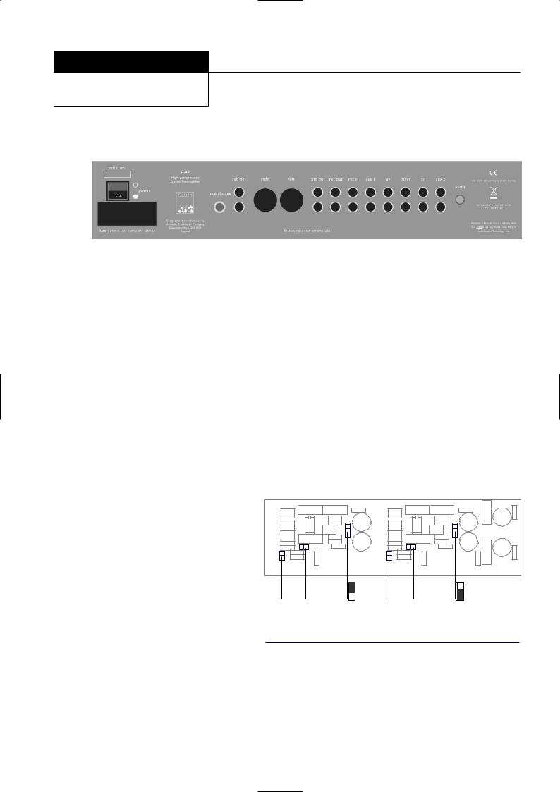
The CA2 accepts unbalanced RCA Phono style inputs sockets. The signal is present on the centre conductor of an unbalanced input and the signal return is made via the screened outer. If there is any hum present on the inputs this must be traced to its source and not suppressed by the removal of screens or earths. Removal of the screen on an unbalanced input is likely to result in uncontrollably loud hum. The input sockets are illustrated in Diagram 1.
All inputs are line-level sensitivity via RCA phono connectors on the rear panel. Inputs are labelled for CD,TUNER,AV,AUX1 or AUX2 however they are electrically identical and a line level signal from any source equipment type may be connected to any input.
The right-hand (viewed from the rear) pair of AUX 2 input sockets will function as a high-sensitivity phono input if the optional RIAA Vinyl Board is installed. The RIAA circuitry can be configured to accommodate a wide selection of phono cartridge types by setting combinations of the board mounted jumpers (links). Access to the board is gained by removing the top panel of the preamplifier. Diagram 2 illustrates the position of the jumpers on the board while Table A details the cartridge matching options available.
Links are moved by pulling them gently away from the board with a small pair of pliers and are replaced in the appropriate positions as shown in the diagrams. Unused links can be “parked” on the board by setting them at right angles on unused pins.
Diagram 1 - CA2 rear panel and connection sockets
Jumpers J3 and J4 set the input load for each channel of the cartridge. With the jumpers in place the load is 100 ohms. With the jumpers removed the load is 47 kilohms.
Jumpers J1, J2, J5 and J6 set the gain (sensitivity) of the RIAA input. J1 and J2 have two positions A and B. In position A the gain of the RIAA circuit is reduced, in position B the gain is increased. J5 and J6 can have the jumper fitted or removed. When fitted the gain of the circuit is increased. By setting combinations of these 4 jumpers a range of sensitivities can be accommodated.
For example: for a cartridge with a low sensitivity, J1 and J2 would be set in position B while J5 and J6 would both have their jumper fitted. Table A illustrates the input sensitivity and load characteristics available.The manufacturer of the cartridge in use should be able to recommend the appropriate settings.
The left-hand AUX 2 input sockets must not be used when the Phono Board is installed.
Diagram 2 - RIAA Phono Board and Jumpers
|
|
Pos A |
|
|
Pos A |
J5 |
J3 |
J1 Pos B |
J6 |
J4 |
J2 Pos B |
Table A - RIAA Jumper Settings
Jumper settings for 1 Volt Output
Sensitivity |
J1 and J2 |
J3 and J4 |
J5 and J6 |
10.0mV |
Position A |
Fitted (100Ω) |
Removed |
6.7mV |
Position A |
Removed (47kΩ) |
Removed |
5.1mV |
Position B |
Fitted (100Ω) |
Removed |
3.4mV |
Position B |
Removed (47kΩ) |
Removed |
2.2mV |
Position A |
Fitted (100Ω) |
Fitted |
1.4mV |
Position A |
Removed (47kΩ) |
Fitted |
1.1mV |
Position B |
Fitted (100Ω) |
Fitted |
0.7mV |
Position B |
Removed (47kΩ) |
Fitted |
4

P r e a m p l i f i e r |
CA2 |
1 . 5 O u t p u t s
The CA2 rear panel, illustrated in Diagram 1, carries sockets for mainain leftleftandandrightrightoutput;outputape, tapeleftleftandandrightrightoutput,leftoutput and stereoright summedheadphonesmono. Use ouf tputhe headphoand ane outputjack leavesforthestereomain outputsheadphonesunaffected. Use of.Thethefrontheadphonepanel mutejack willfunction,mute whichthe outputdoes notfromaffectthe mainthe headphonestereo outputoutput,and mayalso betheusedsub outputto suppress. the
main outputs when headphones are in use.
Connections to the main output may be from RCA phono Connectisockets ornsXLRto thesocketsmain. Connectionsoutput XLR tosockthetsXLRfollowoutputthe csocketsnv ntifollown of pinthe 1conventionto grou d,ofpinpin21toto signalground,pin“hot”2andto signalpin 3 to“hot”signaland returnpin 3 to(signalsignalground)return. (signalWhen ground)c n ecting. Whento equipmeconnectingt withto equipmentXLR (balanced)with inputsXLR the(balanced)connectorsinputsshouldthe beconnectorswired pinshouldf r pinbe(iewired. 1 topin1, 2fortopin2 and(i.e. 13 to 1,3)2. Ftor2RCAand (ph3 to3)no). Diagramunbalanced3 illustratesconn ctionthe XLRthe “hot”outputandpin arrangementsignal return. (pDiagramns 1 and4 illustrates3) shouldthebecablejoinedarrangementat the RCAforplugconnection. Diagramto3 illustratesbalanced inputsthe . XLR output pin arrangement. Diagram 4
illustrates the cable arrangement for connection to balanced
inputsCables. upDiagramto 50 metres5 illustratesin length maythe becableconnectedarrangementto the mainfor connectionstereo or subto outputsunbalanced. inputs.
Cables up to 50 metres in length may be connected to the main balanced outputs.
1 . 6 O p e r a t i o n
Once connected to mains power and powered-up from the rear panel mains switch, the front panel Standby button (or remote handset Standby button) will switch the CA2 between standby and active modes. In Standby mode the Standby indicator glows RED. Operating the Standby function from either the front panel or remote handset will switch the CA2
into active mode. The RED indicator will extinguish and be replaced by the Input Select indicator showing the current selection in GREEN. Operating the Standby function again will return the CA2 to Standby mode.
Inputs are selected by rotating the input select control in either direction. The control has continuous movement. When it is moved to the last input, further rotation will select the first input.
Diagram 3 - output socket pins
Pin 1, Screen
Pin 3, Signal (return)
Diagram 4 - balanced cable
3 Pin Female XLR |
||
Two Core Screened Cable |
Connector |
|
|
||
Hot |
2 |
|
Return |
||
3 |
||
|
||
Screen |
1 |
|
|
To Power Amp or |
|
|
Monitor Input |
|
Diagram 5 - unbalanced cable |
||
Two Core Screened Cable |
Phono (RCA) |
|
Connector |
||
|
||
|
Hot |
|
|
Return |
|
|
Screen |
|
To Power Amp or
Monitor Input
Diagram 6 - CA2 front panel and controls
5
 Loading...