

Atag Q-Solar Installation & Servicing Instructions Manual

I n s t a l l a t i o n & S e r v i c i n g
Instructions
Q-Solar
These instructions to be retained by user.
8G.51.08.02/01.11 Changes reserved.

Explanations of symbols and signs on the Control Tower display.
display
Central heating on / off
Operation indication (in the rst display position by technical
No heat requirement
0
Ventilation phase
1
Ignition phase
2
Burner active on central heating
3
Burner active on hot water
4
Fan check
5
Burner off when room thermostat is demanding
6
Pump overrun phase for central heating
7
Pump overrun phase for hot water
8
Burner off because of to high ow water temperature
9
Automatic venting programme
A
Solar pump active
Sun
Maximum cylinder temperature achieved(>80°C)
Hot
read out)
Step key Selecting chapters
Domestic hot water (DHW) on / off
Pump programme on / off
Mode key Selecting chapters
From Good-read out to Technical read out (and vice versa):
- Press 5 sec. on the STEP key.
Water pressure is to low (<0,7 bar), FILL
indication remains continuously visible,
the boiler is taken out of operation. The
installation needs to be topped up.
Water pressure is to low (<1,0 bar), ashing FILL will alternate with indication
of water pressure, boiler power of 50%
is possible. The installation needs to be
topped up.
Reset key Unlocking the boiler
in case of error
Water pressure is to high (>2,8 bar), if
HIGH indication remains continuously visible, the boiler is taken out of operation.
The installation pressure needs to be
decreased by draining water.
Installation & Servicing Instructions ATAG Q-Solar
2

Content
1 Introduction ...........................................................................................................................................................................4
2 Rules ................................................................................................................................................................................5
3 Scope of the supply .............................................................................................................................................................. 7
4 Description of the boiler ........................................................................................................................................................7
4.1 Schematic lay out of the Q-Solar ............................................................................................................................ 9
5 Mounting the boiler ............................................................................................................................................................. 10
5.1 Dimensions ........................................................................................................................................................... 11
6 Connecting the boiler .......................................................................................................................................................... 12
6.1 Central Heating system ........................................................................................................................................13
6.2 Expansion vessel .................................................................................................................................................. 14
6.3 Underoor heating system (plastic pipes) ............................................................................................................15
6.4 Gas connection .....................................................................................................................................................15
6.5 Hot water supply ................................................................................................................................................... 16
6.5.1 Secondary DHW Circulation. ................................................................................................................................17
6.6 Condensation drain pipe ....................................................................................................................................... 18
6.6.1 Condensate discharge .......................................................................................................................................... 18
6.7 Flue gas exhaust system and air supply system ..................................................................................................20
6.7.1 Flue system dimensions ....................................................................................................................................... 23
7 Solar circuit .........................................................................................................................................................................24
7.1 Expansion vessel solar circuit ..............................................................................................................................24
7.2 Filling and de-aerating the solar cicuit .................................................................................................................. 24
7.3 Solar pump ...........................................................................................................................................................24
8 Electrical connection ........................................................................................................................................................... 25
8.1 Electrical connections between cylinder and boiler .............................................................................................. 26
8.2 Outside sensor (optional) .....................................................................................................................................28
8.3 Solar absorber sensor ..........................................................................................................................................28
8.4 Calibrating the sensors ......................................................................................................................................... 28
9 Boiler controls .....................................................................................................................................................................29
9.1 Explanation of the function keys ........................................................................................................................... 30
9.2 Solar module ........................................................................................................................................................31
9.3 Functioning of the Solar module ........................................................................................................................... 31
10 Filling and venting the installation ....................................................................................................................................... 32
10.1 Filling the cylinder (secundary DHW circuit) .........................................................................................................32
10.2 Central heating system (primary circuit) ............................................................................................................... 33
11 Commissioning the boiler ..................................................................................................................................................34
11.1 Central Heating system ........................................................................................................................................34
11.2 Hot water supply ................................................................................................................................................... 34
11.3 Solar circuit ...........................................................................................................................................................34
11.4 Adjustments .......................................................................................................................................................... 35
11.5 Activating factory settings (green key function) ................................................................................................... 37
12 Isolating the boiler ............................................................................................................................................................. 38
13 Commissioning ...................................................................................................................................................................38
13.1 Checking for contamination .................................................................................................................................. 39
13.2 Checking the CO2/O2 ..........................................................................................................................................40
13.3 Maintenance activities ..........................................................................................................................................41
13.4 Draining the installation ........................................................................................................................................43
13.5 User's instructions ................................................................................................................................................44
13.6 Maintenance frequency ........................................................................................................................................44
13.7 Warranty ............................................................................................................................................................... 44
14 Technical specications ...................................................................................................................................................... 45
15 Parts of the boiler ............................................................................................................................................................... 46
16 Error indication ................................................................................................................................................................... 48
17 CE Declaration of conformity .............................................................................................................................................. 49
Benchmark Checklist ..........................................................................................................................................................50
Service Record ................................................................................................................................................................... 51
Work on the installation should only be carried out by qualied personnel
with calibrated equipment.
Note:
Handling and storage packages:
- Handle with care. Note the instructions/symbols on the packages
Installation:
- Always read the installation manual before installing the system and putting the system into operation
Technical details:
- See page 11 for dimensions and page 45 for Technical specications.
Installation & Servicing Instructions ATAG Q-Solar
3
1 Introduction
These instructions describe the functioning, installation, use and primary maintenance
of ATAG central heating units for the United Kingdom and Ireland. Where necessary
the different regulations for each country are separately described.
These instructions are intended for the use of a GasSafe Register registered installers
or registered Bord Gais installers in connection with the installation and putting into
operation of ATAG units. It is advisable to read these instructions thoroughly, well
in advance of installation. Separate instructions for use are supplied with the unit
for users of ATAG central heating units. ATAG is not liable for the consequences of
mistakes or shortcomings which have found their way into the installation instructions
or user’s manual. Further, ATAG reserves the right to alter its products without prior
notication.
When delivering the unit, give the customer clear instructions concerning its
use; present the customer with the user’s manual and card.
Each unit is tted with an identication plate. Consult the details on this plate to verify
whether the unit is compliant with its intended location, e.g.: gas type, power source
and exhaust classication.
On completion of the installation the installer or commissioning engineer must ll out
and complete the Benchmark commission section of the boiler log book and hand to
customer or end user for future record keeping. The Benchmark log book must also be
lled out and completed by the service agent following each service call, and returned to
the customer. A copy of the Benchmark commissioning certicate must be returned to
ATAG Heating UK Ltd along with the warranty registration card to register the appliance
for the standard warranty benets
Relevant Installation, Service and User manuals:
- ATAG Monopass Flue system individual
- ATAG BrainQ Digital room thermostat
- ATAG MadQ Cascade-/Zone controller
Installation & Servicing Instructions ATAG Q-Solar
4
2 Rules
The following regulations apply to installation of ATAG central heating units:
The ATAG Q-Solar is only suitable as an individual heating appliance with
DHW supply for houses and small utility applications.
Legislation and Regulations.
Gas Safety (Installation and Use). All gas appliances must by law, be installed by a
competent person, eg. Members of Gas Safe Register and in accordance with the current
Gas Safety Regulation. Failure to install appliance correctly could lead to prosecution.
All Gas Safe registered installers carry a Gas Safe ID card and have a registration
number. You can call Gas Safe Register directly on 0800 408 5577.
In addition to the above regulations this appliance must be installed in compliance with the
current IEE Regulations, the Building Standards (Scotland Consolidation) Regulations.
Regulations and bye laws of the Local Water Authority and the Current Health and Safety
Regulation.
The Benchmark Scheme
Benchmark places responsibilities on both manufacturers and installers. The
purpose is to ensure that customers are provided with the correct equipment for
their needs, that it is installed, commissioned and serviced in accordance with the
manufacturer’s instructions by competent persons and that it meets the requirements
of the appropriate Building Regulations. The Benchmark Checklist can be used to
demonstrate compliance with Building Regulations and should be provided to the
customer for future reference.
Installers are required to carry out installation, commissioning and servicing work in
accordance with the Benchmark Code of Practice which is available from the Heating
and Hotwater Industry Council who manage and promote the Scheme.
Visit www.centralheating.co.uk for more information.
Ireland:
- Irish standard 813
- Domestic gas installations
The current, Electricity at Work Regulation must be complied with and also be in
accordance with the relevant and current editions of the British Standards.
The ATAG Q boiler is a certied appliance and must not be modied or installed in
any way contrary to this Installation Manual.
Manufacturers instructions must not be taken in any way as overriding statutory
obligations.
The ATAG Q is a central heating solar unit with an integrated hot water function. These
units must be connected according to these instructions and all installation norms in
respect of the part of the unit to be connected.
Observe the following rules of safety:
- All work on the unit must take place in a dry environment.
- ATAG units must never be in operation without their housing, except in connection
with maintenance or adjustments (see Chapter 13).
- Never allow electrical or electronic components to come into contact with water.
Carry out the following tasks during maintenance, etc. to an already-installed unit:
- Shut down all programmes
- Close the gas tap
- Remove the plug from the wall socket
- Close the stop cock of the unit’s intake connection
Installation & Servicing Instructions ATAG Q-Solar
5
Take note of the following when maintenance or adjustments are needed:
- The unit must be able to function during these activities; for this reason, the unit’s
supply voltage, gas pressure and water pressure must be maintained. Ensure that
these is not a source of potential danger during these activities.
Following maintenance or other activities; always check the installation of all
parts through which gas ows (using leak-detection uid).
Following maintenance or other activities, always replace the housing and
secure it with the screw behind the door at the front of the casing.
Any electrical immersion heater installed MUST contain a thermal cutout
device that will require to be manually re-set should it operate.
The following (safety) symbols may be encountered in these installation instructions
and on the unit:
This symbol indicates that the unit must be stored away from frost.
This symbol indicates that the packaging and/or contents can be damaged as
a result of insufcient care taken during transport.
This symbol indicates that, whilst still in its packaging, the unit must be
protected from weather conditions during transport and storage.
KEY-symbol. This symbol indicates that assembly or dismantling, must be
carried out.
ATTENTION symbol. This symbol indicates that extra attention must be paid
in connection with a particular operation.
Useful tip or advice
Gas pipe (yellow) Solar ow pipe (yellow)
CH-ow pipe (red) Solar return pipe (orange)
CH-return pipe (blue) Condensate drain pipe (blue)
Cold water pipe (blue) Expansion vessel pipe (red)
Installation & Servicing Instructions ATAG Q-Solar
6
Hot water pipe (red)
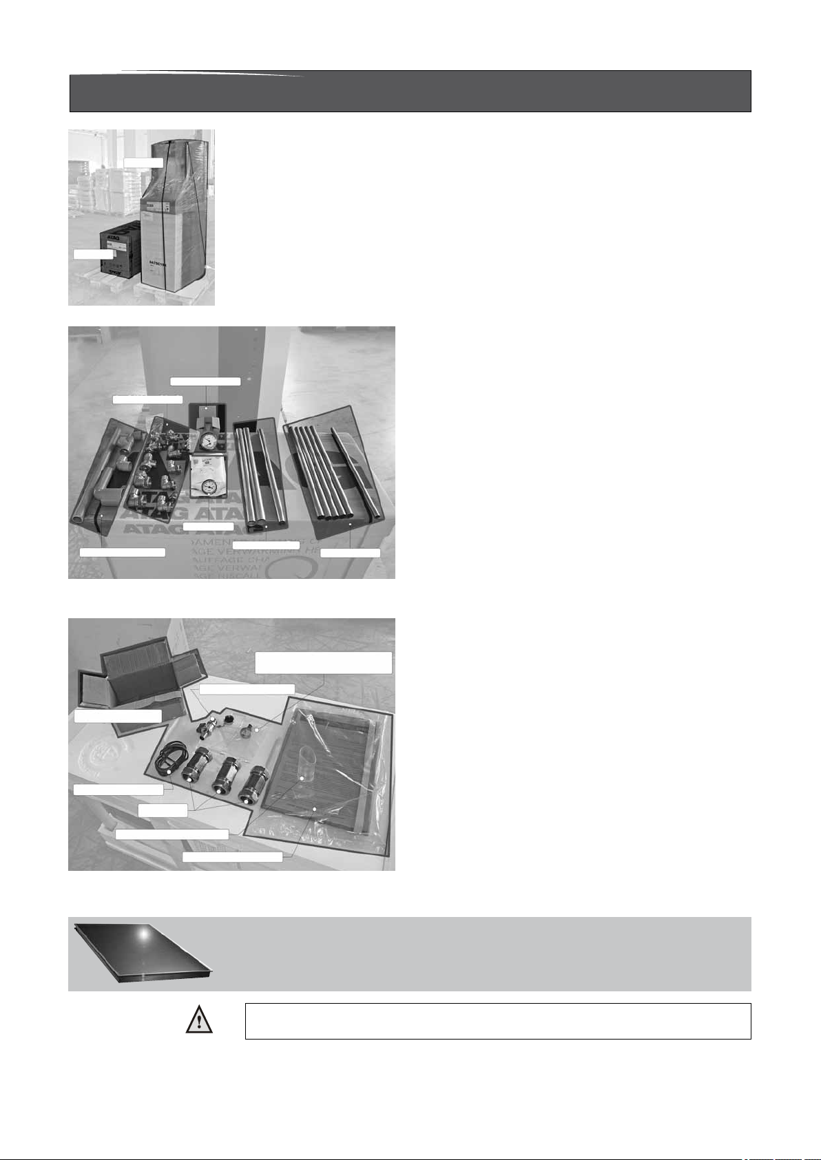
3 Scope of the supply
The boiler is supplied as a 2 part system.
Part 1
Part 2
The supplied kit is composed as follows:
2 Part system Figure 1
Thermomanometer
Fittings
Thermometer
Tundish and pvc piping Cupper piping
Supplied parts with cylinder as separate items Figure 2
Part 1:
Steel piping
Cylinder(3 coils) with casing and integrated:
- Drain valve for boiler.
- Fill and drain valve for solar circuit.
- Safety valve for solar circuit.
- Expansion vessel solar circuit 18 litre.
- Solar pump with non return valve.
- Flow restrictor
- Modulating 3-way valve (VC6940 Solar/CH).
- Thermostatic mixing valve.
- Temperature and pressure relief valve.
- DHW pressure reducing valve.
- DHW single check valve.
- DHW expansion vessel.
- DHW expansion relief valve.
And:
- Thermometer /thermomanometer.
- Tundish.
- Installation manual.
Spare compression ring 28mm,
Cap de-aerator and casing screw
Draining valve
Box for ttings
Absorber sensor
Fittings 28mm
Boiler condensate drain
Documentation
Supplied parts with boiler as separate items Figure 3
Thermal Absorber
The thermal absorber is not a standard part of the delivery. The thermal absorber
should be obtained from a third party. The thermal absorber should t to the specications of the Q-Solar.
The supplied absorber sensor PT100 ø6mm should be mounted in the correct position in the absorber.
Please contact the supplier of the absorber.
Part 2:
Boiler with casing and integrated:
- Automatic de-aerator;
- Safety valve;
- 3-way valve (VC2010 CH/DHW);
And:
- Fitting 28mm (3x);
- T-piece 22 x 1/2" x 22 + draining valve;
- Absorber sensor PT100 ø6mm;
- Installation manual;
- Operating manual;
- Warranty card;
- Benchmark logbook.
Installation & Servicing Instructions ATAG Q-Solar
7

4 Description of the boiler
Room sealed boiler
The boiler retreives its
combustion air from
outside then discharges
the ue gasses to the
outside.
Condensing
Retrieves heat from
the ue gasses. Water
condensates on the heat
exchanger.
Modulating
Higher or lower burning
according to the heat
demand.
Stainless
Super solid kind of steel
which keeps its quality for
life. It will not rust or erode
in contrast to composition
materials, like aluminium.
The ATAG Q-Solar boiler is a room sealed, condensing and modulating central heating
boiler, with or without an integrated hot water facilities which uses thermal solar power.
The boiler is provided with a compact stainless steel heat exchanger with smooth
tubes. A well thought out principal using durable materials.
The boiler burns gas for supplying warmth. The heat is transferred in the heat
exchanger to the water in the central heating system. By cooling down the ue gasses
condensate is formed. This results in high efciency. The condensate, which has no
effect on the heat exchanger and the function of the boiler, is drained through an
internal siphon.
The boiler is provided with an intelligent control system (CMS Control Management
System). The boiler anticipates the heat demand of the central heating system or the
hot water facility.
When an outside sensor is connected, the boiler reads it and works weather
dependantly. This means that the boiler control measures the outside temperature
and ow temperature. With this data the boiler calculates the optimal ow temperature
for the installation.
The Q-Solar functions in combination with a thermal absorber. The solar circuit is a
closed pressurised glycol circuit.
The cylinder is specically designed and constructed for this purpose. The cylinder
should not be used for other purposes.
Solar functioning in short:
The solar pump is activated as soon as the temperature of the absorber is approx.
10ºC higher than the temperature in the cylinder (T > 10ºC: pump on). The glycol
will be transported from the cylinder through the absorber and back. The glycol is
heated in the absorber. The heat is transferred to the sanitary water through the solar
coil in the cylinder.
The pump is deactivated as soon as the temperature of the absorber is approx. 2ºC
higher than the temperature in the cylinder (T < 2ºC: pump off). The pump is also
deactivated if all of the sanitary water in the cylinder has reached a temperature of
80ºC. This means that there is no chance of overheating! In addition, the cylinder is
provided with a T&P valve and the solar circuit is provided with a pressure relief valve.
The heating circuit is supplied with solar warmth from the CH coil in the middle of
the cylinder. This is especially suitable for low temperature installations, like under
oor heating systems. When the cylinder has sufcient hot water and there is a heat
demand for the heating circuit the modulating 3-way valve will be activated. The
heating circuit will be supplied by water across the CH coil of the cylinder. If the heat
demand is larger than the availability in the cylinder, the heating circuit will be heated
by the gas red boiler.
Explanation of the type indication: ATAG Q38SC380N
Q = Type
38 = Nominal load in kW
SC = SolarCombi
380 = content of the cylinder
N= Not vented glycol solar circuit
Installation & Servicing Instructions ATAG Q-Solar
8
The boiler has been tested according to valid CE* standards and has a CE* certicate
and SEDBUK A-rating.
Statement: No banned materials including asbestos, mercury, CFC's have not or will
not be included in the product.
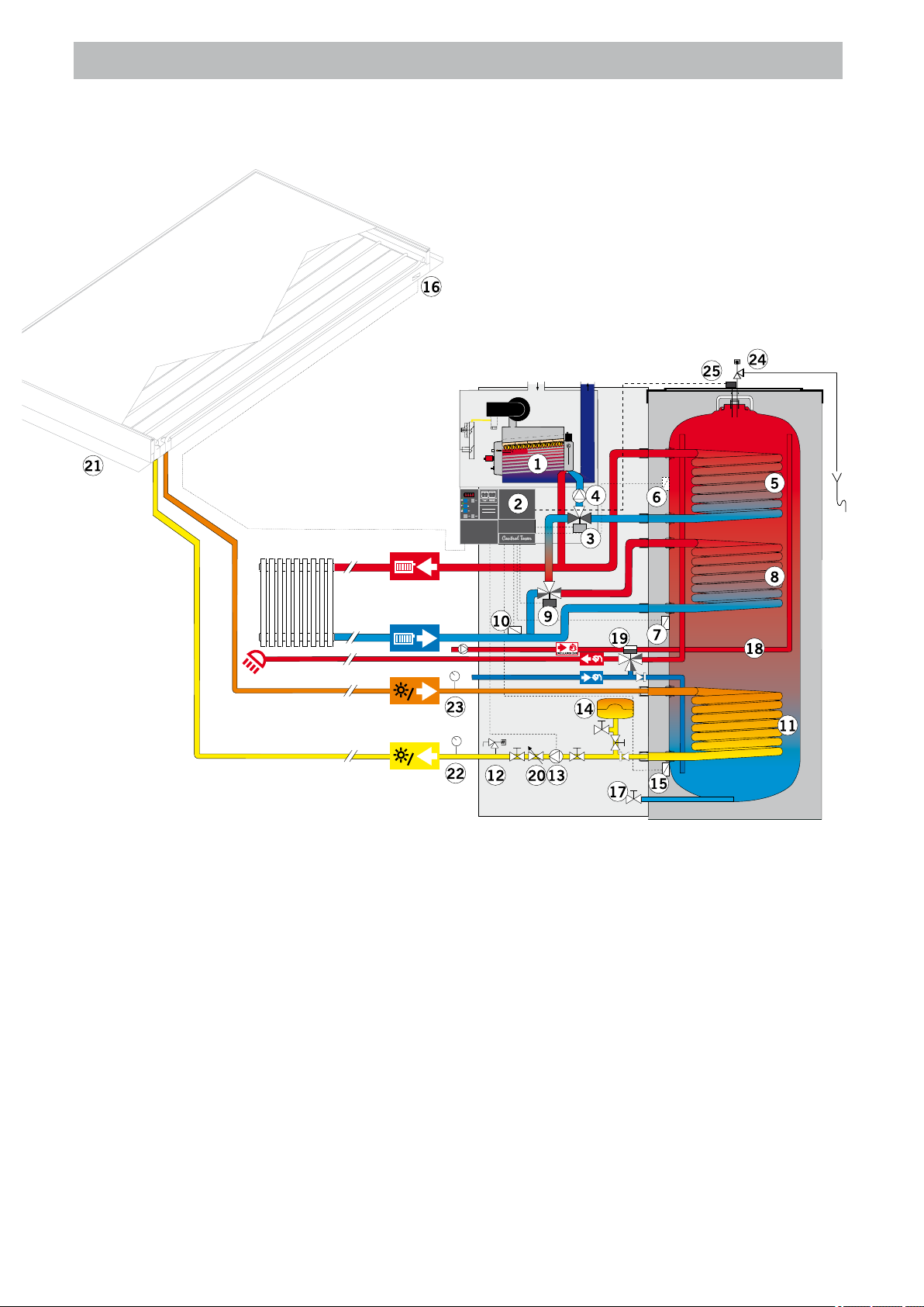
4.1 Schematic lay out of the Q-Solar
Schematic lay out Q-Solar system Figure 4
1. Stainless steel OSS heat exchanger
2. Control Management System (CMS) with Solar module
3. 3-Way valve (CH/DHW)
4. Boiler pump
5. DHW coil
6. DHW sensor
7. CH-Solar sensor
8. CH coil
9. Modulating 3-way valve (CH-Solar)
10. CH-Solar return sensor
11. Solar coil
12. Drain valve and relief valve solar circuit
13. Solar pump
14. Expansion vessel
15. Cylinder sensor Solar (Delta-T)
16. Absorber sensor Solar (Delta-T)
17. Cylinder drain valve
18. DHW circulation pipe
19. Thermostatic mixing valve
20. Adjustable ow restrictor
21. Solar asorber
22. Pressure/temperature gauge
23. Pressure/temperature gauge
24. Temperature and pressure relief valve
25. High limit thermostat
Installation & Servicing Instructions ATAG Q-Solar
9
5 Mounting the boiler
The room where the boiler will be placed must always be frost free. To prevent heat
loss the boiler should be placed as close as possible to the absorber and, if possible,
as close as possible to the most used DHW tap(s).
It is NOT necessary to have a purpose provided air vent in the room or internal
space in which the boiler is installed. Neither is it necessary to ventilate a cupboard
or compartment in which the boiler is installed, due to the extremely low surface
temperature of the boiler casing during operation. Therefore the requirements of BS
6798, Clause 12, and BS5440:2 may be disregarded.
The Q-Solar is a oor standing (upright) boiler. The oor on which the boiler will be
placed must be at and of sufcient strength in order to be able to carry the boiler
weight with its total water content.
Above the boiler there must be at least 250 mm working space in order to be able to t
a coaxial ue system or a twin supply. Take account of enough space around the boiler
in order to make connections to the boiler and installation, and allowing for access to
carry out repair and replacement of components.
- First position the cylinder [section 1] in the desired place and adjust it
vertically using the adjustment foot at the bottom of the cylinder.
- Slide the supplied ttings (3x 28mm) on the pipe connections on which the boiler
(colli 2) has to be connected. Take note of the right position (see gure 1).
- Lift the boiler (Section 2) and hang it on the 2 suspension points at the top of the
cylinder. Ensure that the boiler is correctly attached to these points.
When removing the plastic sealing caps from the pipes, contaminated testing
water may be released.
Lift the boiler only by the boilers rear wall.
Lifting and carrying precautions:
- Lift only a manageable weight, or ask for help.
- When lifting the boiler, bend the knees, and keep the back straight and feet apart.
- Do not lift and twist at the same time.
- Lift and carry the boiler close to the body.
- Wear protective clothing and gloves to protect from any sharp edges.
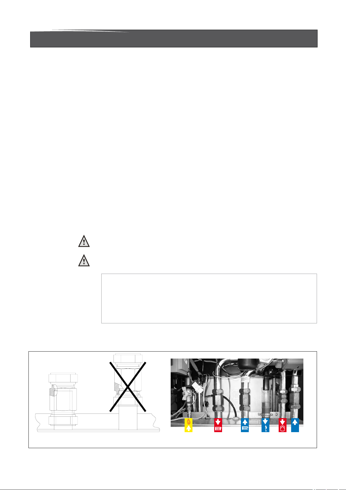
- Slide the tting upwards until the touch rim and tighten the nuts.
- Move the gas pipe and expansion vessel pipe upwards and connect them.
Use only approved ttings on the gas supply.
Gas Flow Return Condensate Expansion Cylinder
drain vessel return
Fittings Figure 5
Installation & Servicing Instructions ATAG Q-Solar
10
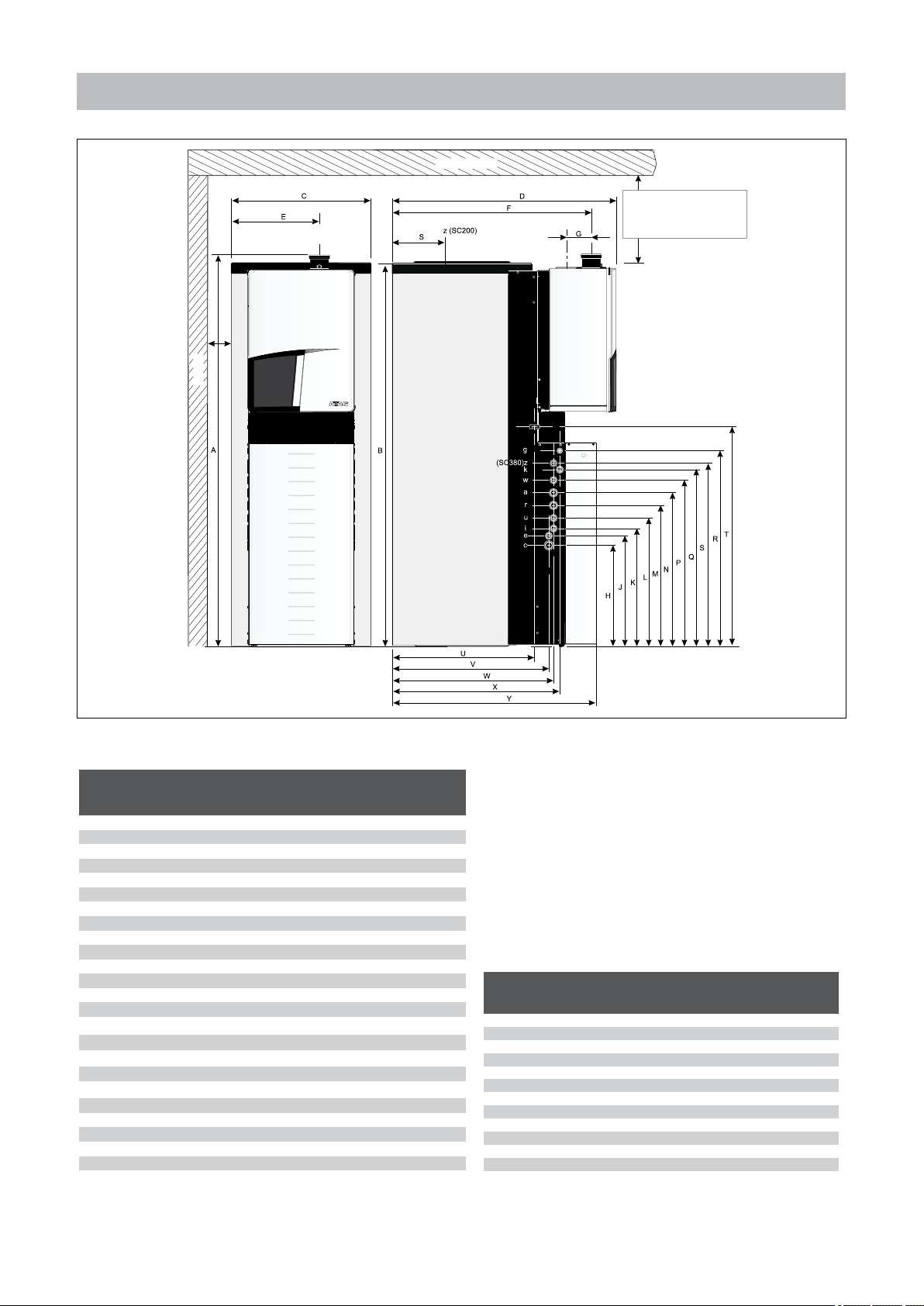
5.1 Dimensions
150
Wall
Ceiling
Flue system
ø80/125: min. 250 mm
ø100/150:min. 480mm
230V power supply cable feed through
Dimensions Q-Solar (See Table 1 and 2) Figure 6
Boiler type
A Height total 1880 1860
B Height cylinder 1820 1830
C Width 510 660
D Depth 895 1040
E Left side / Flue gas 340 415
F Back side / Flue gas 780 920
G Centre to centre flue gas and air supply 120 120
H Condensate pipe - c 480 480
J Expansion vessel pipe - e 525 525
K Flow pipe solar absorber - i 560 560
L Return pipe solar absorber - u 610 610
M CH return pip - r 670 670
N CH flow pipw - a 730 730
P DHW pipe - w 790 790
Q Cold water pipe - k 850 840
R Gase pipe - g 930 930
S DHW circulation pipe - z top side cyl. 870
T Supply cable 1040 1040
U Supply calbe 510 675
V Pipes c and e 580 744
W Pipes i, u, r, a, w and k 600 766
X Pipe g 636 796
Y Front cylinder casing 810 970
Q-Solar
Q25SC200 Q25SC380
Q38SC200 Q38SC380
mm mm
Boiler type Q-Solar
Q25SC200 Q25SC380
Q38SC200 Q38SC380
mm mm
Air supply / Flue gas ø 125 / 80 ø 125 / 80
Flue gas ø 80 ø 80
Gas pipe - g ø15 x 1/2"int. ø15 x 1/2"int.
CH flow pipe - a ø28x1"ext. ø28x1"ext.
CH return pipe - r ø28x1"ext. ø28x1"ext.
Condensate pipe - c ø32 ø32
Cold water pipe - k ø22 x 3/4"ext. ø22 x 3/4"ext.
DHW pipe - w ø22 x 3/4"ext. ø22 x 3/4"ext.
Flow pipe solar absorber - i ø22 ø22
Return pipe solar absorber - u ø22 ø22
Expansion vessel pipe CH - e ø22 ø22
DHW circulation pipe - z 1/2" ø22
Dimensions Table 1
Connection diameters Table 2
Installation & Servicing Instructions ATAG Q-Solar
11
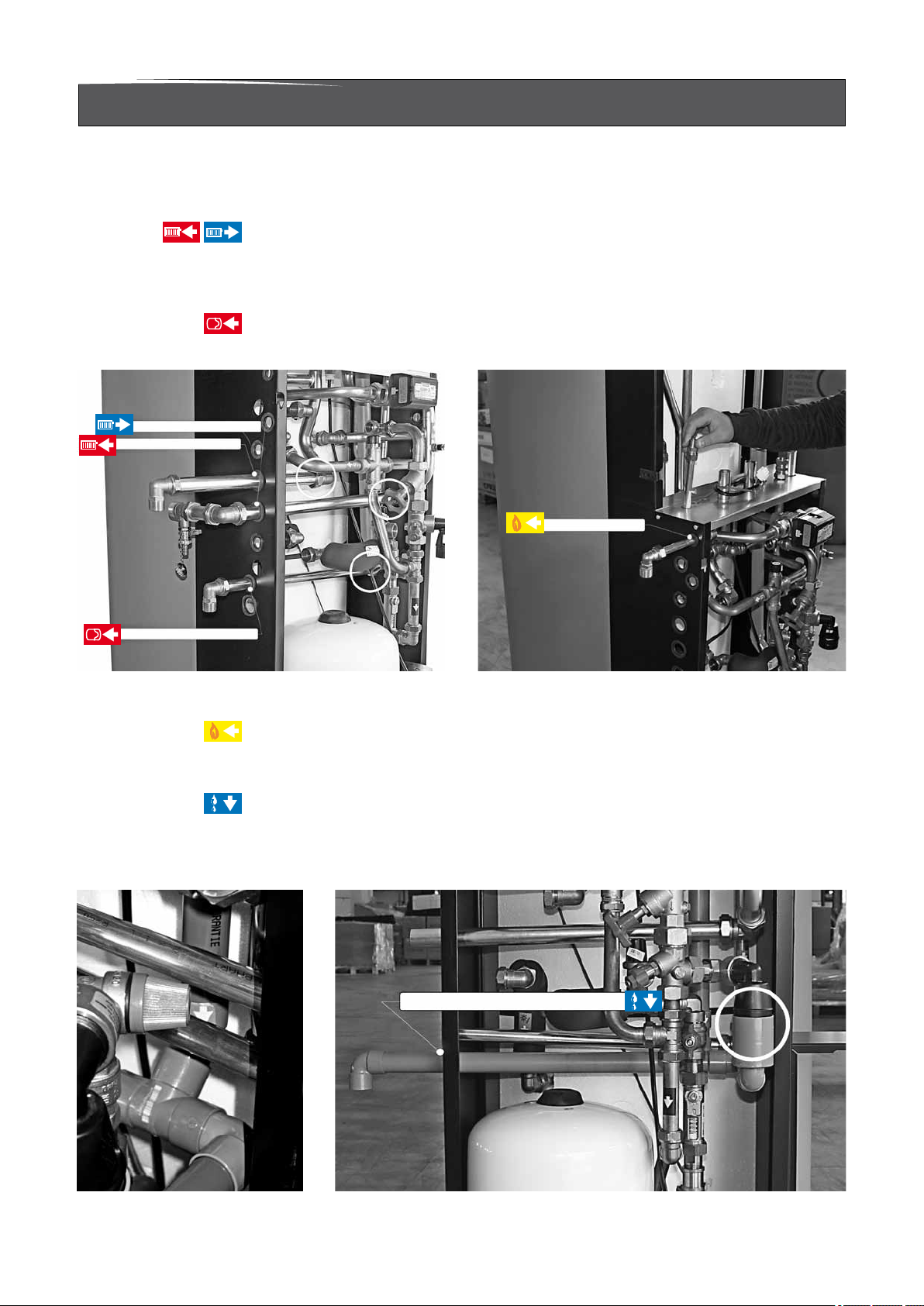
6 Connecting the boiler
The boiler has the following connection pipes, which can be connected left or right
to the boiler by means of turning the knee tting (all connections are positioned
to the left from factory);
- The central heating pipes (See gure 7).
These can be connected to the installation by means of the supplied compression
ttings(1xT-piece) 28 mm x1" and the 28mmx480mm pipes. The supplied drain
valve can be tted on the T-piece in the return pipe. See further chapter 6.1.
- CH expansion vessel pipe (See gure 7).
On this 22mm x480mm pipe and 22mmx3/4" tting the CH expansion vessel should
be mounted See further chapter 6.2.
Return from central heating
Flow to central heating
Gas pipe
Expansion vessel CH
Central heating and expansion connections Figure 7 Gas pipe connection Figure 8
- The gas pipe (See gure 8).
This can be tted to the boiler with a 1/2"x15mm tting to the boiler.Outside the
boiler the gas pipe has to be provided with a manual gas valve within 1 metre of
the boiler. See further chapter 6.4.
- The condensation drain pipe (See gure 9).
It consists of an oval 24 mm plastic pipe. The drain pipe can be connected to this
by means of a tundish. The drain pipe is provided with a syphon. The drain pipe
can be connected (glued) outside the boiler to a 32 mm PVC drain. See further
chapter 6.6.
Condensation drain pipe (380 Litre)
Condensation drain pipe Figure 9
Installation & Servicing Instructions ATAG Q-Solar
12

Cold water pipe
Hot water pipe
- Cold and hot water pipes (See gure 10).
These consist of 22mm copper pipes and can be connected to the installation by
means of compression ttings. See further chapter 6.5.
Flow to absorber
Return from absorber
Secondary circulation pipe
Cold and hot water pipe connections Figure 10 Absorber pipe connections Figure 11
(only 380 litre)
Thermomanometer
Thermometer
- Absorber pipes (See gure 11).
These consist of 22mm heat resistant insulated copper pipes. The complete
absorber circuit has to be connected with heat resistant 22mm copper pipe
with the supplied T-pieces 22mmx22mmx1/2". The supplied thermometer and
thermomanometer should be tted to the T-pieces. See further chapter 7.
- The ue gas exhaust system and air supply system.
It consists of a concentric connection 80/125 mm. See further chapter 6.7.
It is recommended that isolation valves are tted to all heating and hot water
connections to facilitate ease of future maintenance.
It is advisable to spray-clean all of the unit’s connecting pipes and/or to
spray-clean/blow-clean the installation before connecting it to the unit.
Installation & Servicing Instructions ATAG Q-Solar
13
6.1 Central Heating system
Connect the central heating system according to local regulations.
The boiler pipes can be connected to the installation by means of compression ttings.
Reducers should be used for connecting to thick-walled pipe (welded or threaded).
Install the drain valve with the T-piece in the CH return pipe within reach.
It is not necessary to install a heat trap in the central heating pipes. This is already
present in the cylinder.
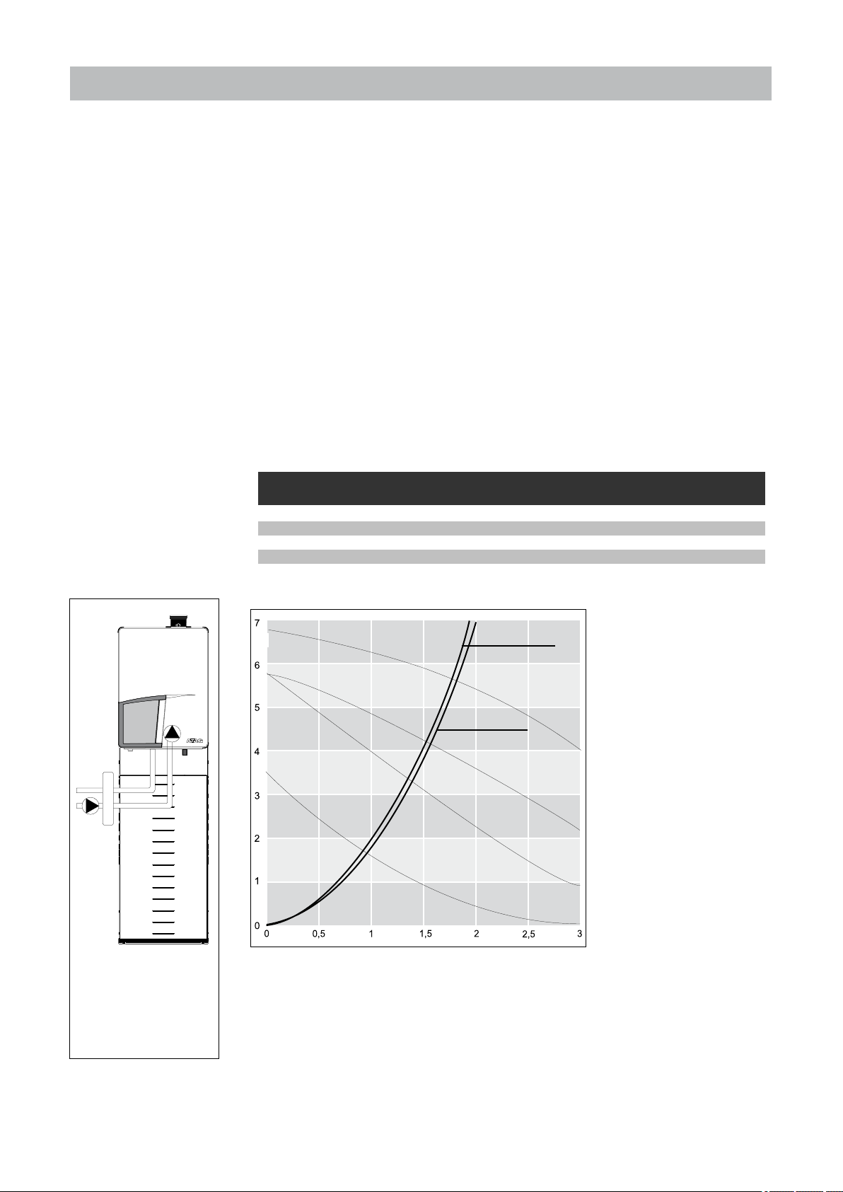
The boiler has a self-adjusting and self-protecting control system for the load and the pump
capacity. This means the temperature difference between the ow and return water is
checked. Table 3 shows the water displacement which supplies the circulation pump
at certain installation resistance.
If the installation resistance is higher than the stated value the pump will rotate at
maximum pump capacity and the load will be adjusted until an acceptable temperature
difference between ow and return water has been obtained. If, after this, the
temperature difference remains too much then the boiler will switch itself off and wait
until an acceptable temperature has arisen.
If an unacceptable temperature is detected, then the control will repeatedly try to
achieve water ow, and if this does not work then the boiler will switch off.
Boiler type Pump type
UPER l/min l/h kPa mbar
Q25SC200 20-60 16,2 972 32 320
Q38SC200 20-70 24,6 1478 16 160
Q25SC380 20-60 16,2 972 32 320
Q38SC380 20-70 24,6 1478 16 160
Installation resistance Table 3
100%
H(m)
UPER 20-70
Water flow rate permissible installation
resistance
Q38SC200
Q38SC380
100%
UPER 20-60
25%
UPER 20-70
Q25SC200
Q25SC380
25%
UPER 20-60
* W h e n a n e x t e rn a l
in sta lla tion pu mp is
connected to terminal
po i n t s 4 ,5,6 in t h e
Control Tower the pump
will switch parallal to the
boiler pump.
External installation pump
with low velocity header
Figure 12
Installation & Servicing Instructions ATAG Q-Solar
14
Q(m³/h)
pump index lines Graph 1
If the capacity of the boiler pump is insufcient, an extra external pump can be installed
installation height above
the expansion vessel
pre-charge pressure
of the expansion vessel
5 m 0,5 bar
10 m 1,0 bar
15 m 1,5 bar
in combination with a low velocity header in series with the boiler. The electrical side
of this external circulation pump can be connected in the Control Tower, by which
means this pump switches at the same times as the boiler pump.
The maximum absorbed current consumption of the external circulation pump may be
230 W (1 Amp). The extra external pump must be selected according to the installation
resistance and required ow.
As standard the boiler is provided with a water lter in the return pipe of the boiler.
With this, possible contamination of the central heating water is prevented from ending
up in the boiler. The boiler is also provided with an internal safety valve set at 3 bar.
This is connected to the waste discharge together with the condensation discharge.
If all, or a large part of the radiators are provided with thermostatic radiator valves
it is advisable to use a pressure difference control (bypass) in order to prevent ow
problems in the installation.
The boiler is designed to be used on sealed systems only.
Additives in the installation water are only permitted in consultation with
the country distributor. ATAG Heating UK Ltd recommend the use of either
Fernox or Sentinel products.
6.2 Expansion vessel
The central heating system must be provided with an expansion vessel. The expansion
vessel which is used should be geared to the water content of the installation.
The pre-charge pressure depends on the installation height above the mounted
expansion vessel. See table 5.
choice of expansion vessel table 5
All Q-Solar boilers are provided with an expansion vessel connection. This pipe is
connected between the three way valve and boiler pump. This prevents the expansion
water produced during heating or hot water operation from being closed off from the
expansion vessel, when the thermostatic radiator valves are fully closed.
In connection with correct functioning of the boiler it is necessary for the
expansion vessel to be connected to the expansion vessel pipe of the boiler.
Installation & Servicing Instructions ATAG Q-Solar
15

6.3 Underoor heating system (plastic pipes)
When connecting or using an underoor heating system, designed with plastic
pipes, or plastic pipes are used elsewhere in the installation,one should ensure that
the plastic pipes used comply with the DIN 4726/4729 standard. It is set out in this
standard that the pipes may not have oxygen permeability higher than 0.1 g/m³.d at
40°C. If the system does not comply with this DIN standard, the underoor heating
component will have to be separated from the central heating appliance by means
of a plate exchanger.
Take care that a system with plastic pipes is well de-aerated and remains well deaerated.
No recourse can be made to the terms of the warranty in the event of failure
to observe the regulations pertaining to plastic underoor heating pipes.
6.4 Gas connection
Determine the correct diameter of the gas line and connect it to the boiler along with
a gas isolation valve within 1 metre of the boiler.
United Kingdom:
The gas supply must comply to the current Gas Safety Installations & Use Regulations.
LPG
Ireland:
- Irish standard 813
- Domestic gas installations
The connection to the appliance must include a suitable method of disconnection and
a gas control cock must be installed adjacent to the appliance for isolation purposes.
The nominal inlet working gas pressure measured at the appliance should be 20 mbar
for Nat gas (G20).
Make sure that the gas pipe work does not contain dirt, particularly with new
pipes.
When the boiler has to be converted from natural gas to LPG, ATAG provides special
kits for this purpose. Special instructions are supplied with the kit.
Always check the installation of all of the parts through which gas ows
(using leak detection uid)
Installation & Servicing Instructions ATAG Q-Solar
16
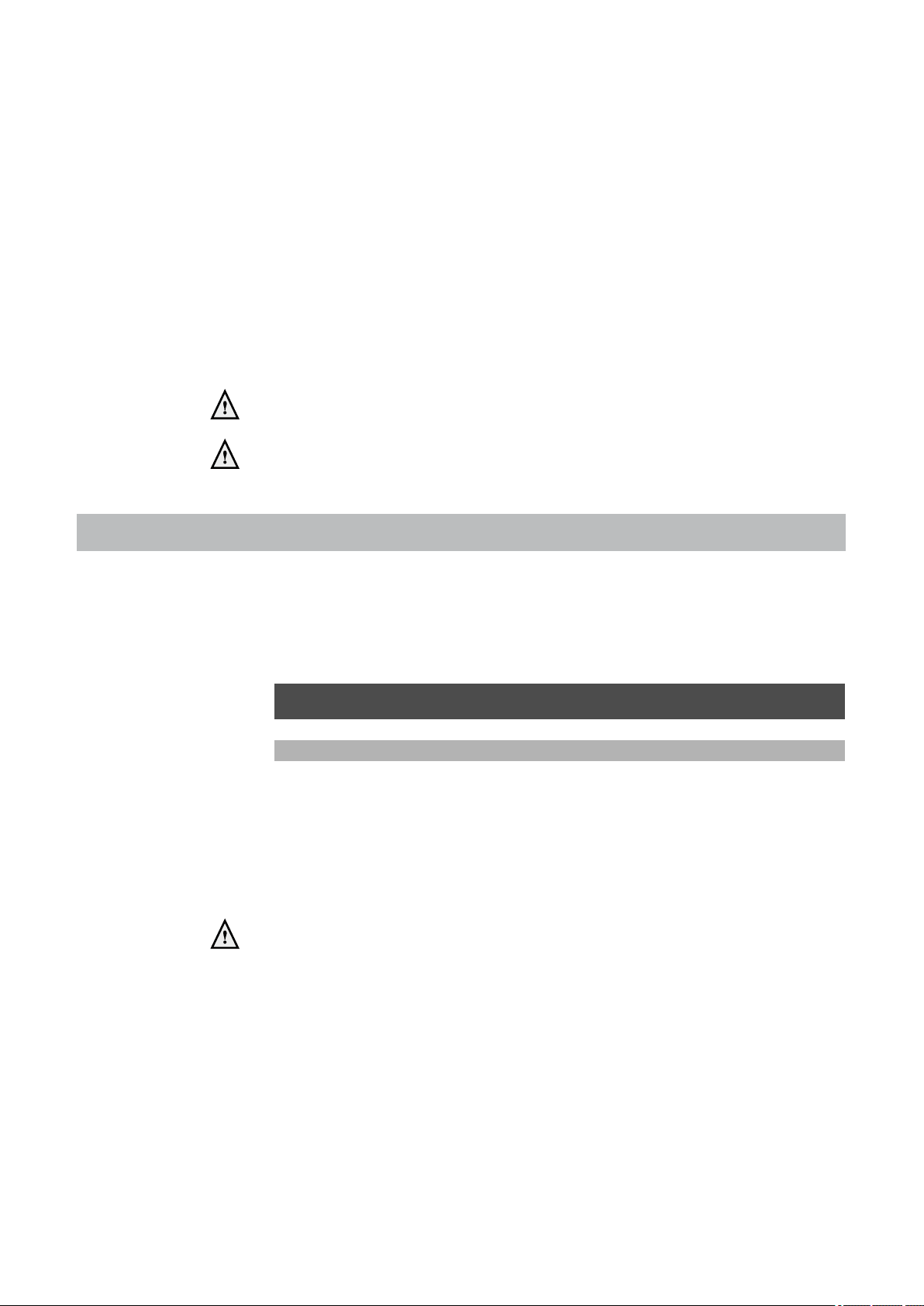
6.5 Hot water supply
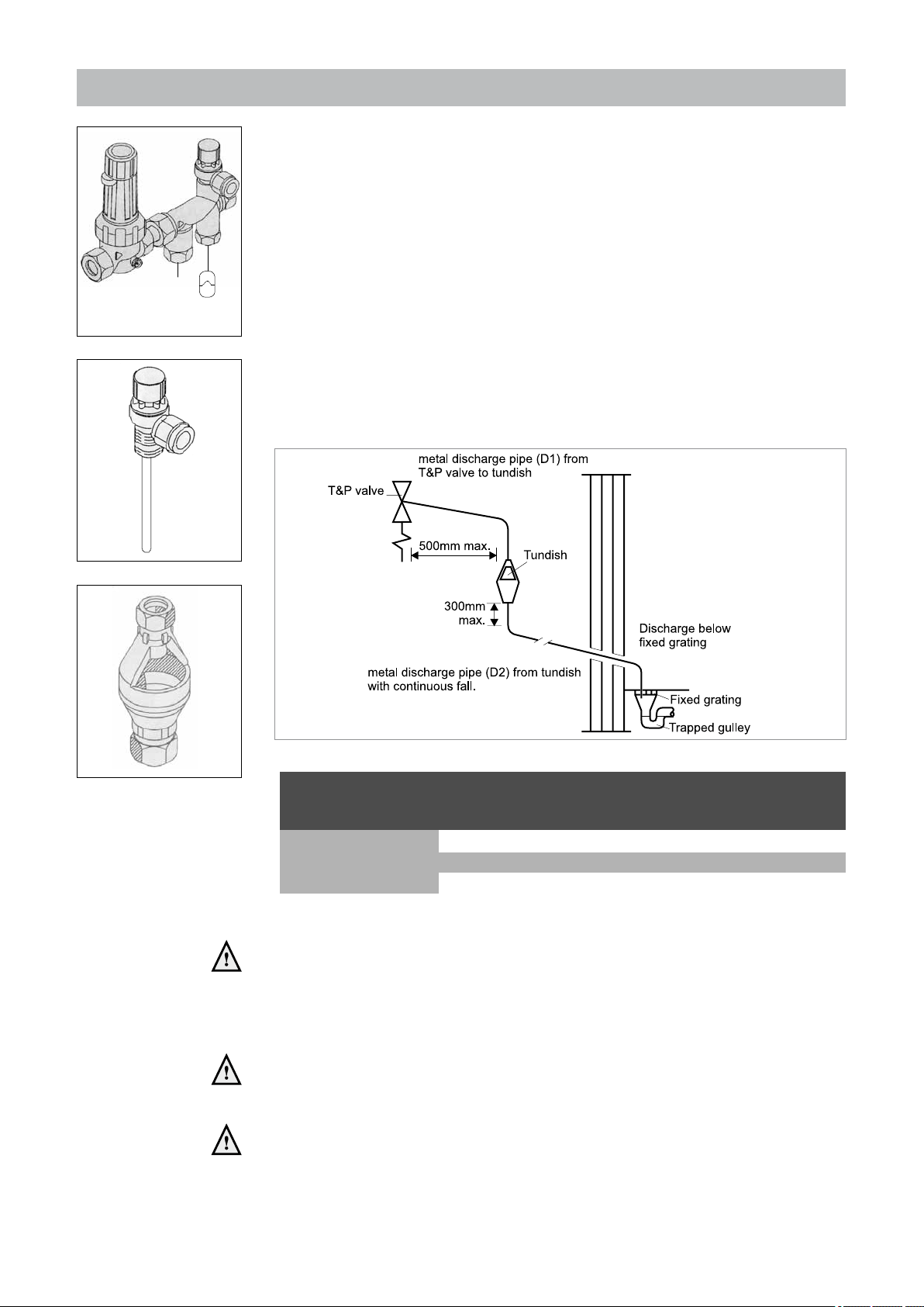
Valve
outlet
size
Minimum size
of discharge
pipe (D1)
Minimum size of
discharge pipe
from tundish (D2)
Maximum resistance
allowed, expressed as a
length of straight pipe
Resistance created
by each bend or
elbow
G 3/4" 22mm
28mm up to 9m 1.0m
35mm up to 18m 1.4 m
42mm up to 27m 1.7m
Balanced water
supply
DHW expansion
vessel (blue)
safety group Figure 13
Connection of the drinking water installation should be done according to the national
water laws.
The sanitary water pipes can be connected to the installation by means of compression
ttings. The cold water inlet must be provided with the supplied DHW safety group
(see gure 13) consisting of (counted in the water ow direction):
- Pressure reducing valve with integral strainer
- Check valve
- Core unit
- Expansion vessel 6bar (potable water, blue)
- Expansion valve with tundish
The cylinder is provided with a temperature and pressure relief valve (T&P valve) on
top of the cylinder (see gure 14).
Install the tundish of the T&P valve according gure 16 and table 6.
T&P valve Figure 14
tundish Figure 15
installation of the T&P valve tundish Figure 16
dimensions discharge pipes T&P valve table 6
Above mentioned items may be used for their specic purposes only and
have to be visible to occupants and kept away from electrical devices.
If a DHW secondary circulation line has to be installed take account of the extra
volume regarding the size of the expansion vessel.
Cylinder relief valve connections should not be used for any other purpose
and no valve should be tted between the expansion valve and the storage
cylinder.
Thermosat and thermal cut-out are integrated in the boiler and may not be
changed. Therefore it is not allowed to t an immersion heater.
Installation & Servicing Instructions ATAG Q-Solar
17

Take account of the hardness of the water. Take precautions to prevent
scaling in the cylinder.
In regions with a water hardness value higher than 267ppm (2,67 mmol/l),
calcium deposits should be removed from the cylinder on a regular basis.
If problems occur when using sanitary water with a chlorine content higher
than 150 mg/l, no recourse can be made to the terms of the warranty.
The hardness of the water is variable in Great Brittain and Ireland. The water company
can provide exact information about this.
6.5.1 Secondary DHW Circulation.
In case of long DHW pipe runs one can connect a secondary circulation pipe to the
Q-Solar. This improves the comfort because the waiting times can be reduced to a
few seconds
The return of this pipe is connected to position Z on the Q-Solar.
The pump of this secondary circulation is not part of the delivery and has to be sourced
elsewhere. Please make sure that this is a DHW circulation pump.
It is good practice to put a time clock on the pump so that it only runs during hours
of possible hot water usage.
Installation & Servicing Instructions ATAG Q-Solar
18
 Loading...