

Page 1
8G.51.10.00/10.05
INSTALLATION MANUAL
MadQ/2
MadQ/2 Controller
Page 2

GB English
Page 3

GB-3
Contents
General safety instructions..............................................................................GB-4
Safety measures for EMC - compliant installation.........................................GB-4
Installation of the control unit.........................................................................GB-6
Mounting instructions .................................................................................... GB-6
Electrical installation...................................................................................... GB-6
Electrical connection ..................................................................................... GB-7
Installation set MadQ .................................................................................... GB-8
Wall-mounting case .......................................................................................GB-9
Assembly and electric installation .................................................................. GB-9
Electrical connections ................................................................................. GB-10
Thermostats (for remote- control) .............................................................. GB-11
Mounting Location....................................................................................... GB-11
Mounting instructions .................................................................................. GB-11
Electrical connection ................................................................................... GB-12
Electrical connection at control unit ............................................................ GB-12
Data bus allocation...................................................................................... GB-12
Accessories ..................................................................................................GB-14
Outdoor sensor ........................................................................................... GB-14
Tank sensor ................................................................................................ GB-15
Flow sensor................................................................................................. GB-15
Resistance values of sensors depending on temperature.......................... GB-16
Commissioning the control unit .................................................................GB-17
Code input................................................................................................... GB-17
Automatic setting function..........................................................................GB-18
Alarm messages...........................................................................................GB-19
Plant information ..........................................................................................GB-20
Parameter synoptic ......................................................................................GB-23
Overview of installer parameters and adjustment options.......................... GB-25
Appendix ................................................................................................................ I
GB
Page 4
GB-4
General safety instructions
All electrical connections and safety
measures have to be carried out by a
specialist in due consideration of valid
standards and VDE-guidelines as well as
the local regulations.
The electrical connection must be a
permanent connection in accordance with
VDE 0100).
The electrical connection must be in
compliance with the specifications of the
ATAG boiler.
Important!
Deenergize the boiler or wall-mounting
case before opening.
Unprofessional plugging attempts under
voltage may damage the control or
cause dangerous electrical shocks.
Safety measures for EMC compliant
installation
1. Cables with mains voltage must be
generally routed separately from
sensor lines and data bus cables.
A minimum distance of 2 cm between the
lines is mandatory. Crossing of lines is
permitted.
2. For control units with their own mains
connections, ensure the power-,
sensor- and bus lines are routed
separately. If cable ducts are in use,
they must be equipped with separators.
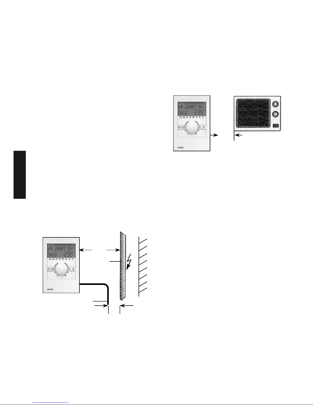
3. When installing the control units or
thermostats, a minimum distance of 40
cm must be maintained to other
electrical utilities with electromagnetic
emissions, such as radio`s, motors,
transformers, dimmer switches,
microwave ovens and televisions,
loudspeakers, computers, radiophones
etc.
4. A minimum distance of 40 cm between
the thermostats and control units is
mandatory. Several control units in a
data bus connection may be installed
directly side by side.
Fig. 1: Minimum distances during electrical
installation
Fig. 2: Minimum distance to other electric
instruments
40 cm
15 cm
Mains
230 V~
Data bus line 12 V
2c
m
GB
Page 5
GB-5
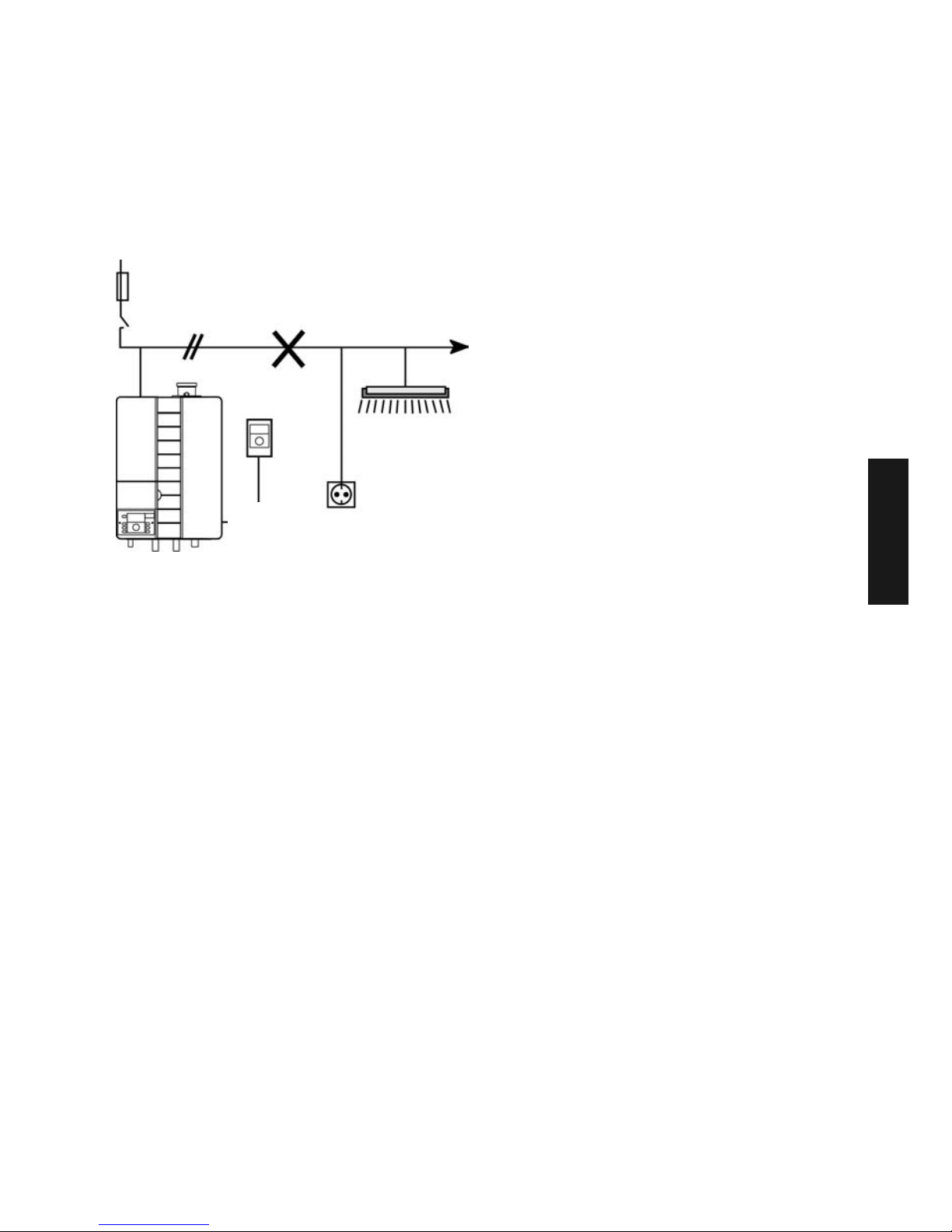
5. The main connection for the heating
system (i.e. boiler control panel control unit) must be designed as an
independent electrical circuit. There
should no fluorescent lamps or other
machines, which may be sources of
disturbance, be connected and even
the possibility of such connections
should be ruled out.
6. The outside sensor may not be
installed close to transmitting or
receiving equipment (on garage walls
close to receivers for radio-controlled
garage door openers, amateur radio
antennas, radio controlled alert
systems or close to large scale radio
transmission equipment).
Recommended cable cross-sections
and maximum permitted cable lengths:
For all cables with mains voltage (power
supply, burner, pumps, actuators)
1.5 mm
2
Maximum length:
Unlimited cable length within house
installation.
All low voltage cables (sensors, external
switches due to demands via contact
points, modem connection cables,
analogue signal cables etc.): 0.5 mm
2
Maximum length:
100 m (duplicate wire)
Longer connecting cables should be
avoided in order to reduce the risk of
interfering radiation.
Data bus line: 0.6 mm Ø
Maximum length:
50 m (duplicate wire)
Longer connecting cables should be
avoided in order to reduce the risk of
interfering radiation.
Fuse 16 A
Heating room emergency switch
Only connect heating
room lighting and
sockets on separate
power circuit!
Thermostat(s
)
ATAG - burner
Fig. 3: Electric routing in heating room
GB
Page 6
GB-6
Installation of the control unit
Mounting instructions
Parts necessary for the installation into the
boiler control unit:
- MadQ control unit 23BC or 233BVVC
- MadQ installation set for 23BC or
233BVVC
Parts necessary for the installation into the
wall-mounting case:
- MadQ control unit 23BC or 233BVVC
- MadQ wall-mounting case
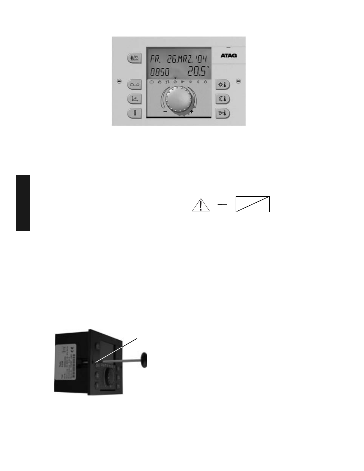
All control units can be built into the
corresponding ATAG boiler control unit or
wall-mounting case after the electrical
connections have been made.
They should be fastened with quickclamping devices (1) by turning them
clockwise.
The removal is done in reverse order. See
the assembly instructions that belong to
the MadQ installation set and the MadQ
wall-mounting case.
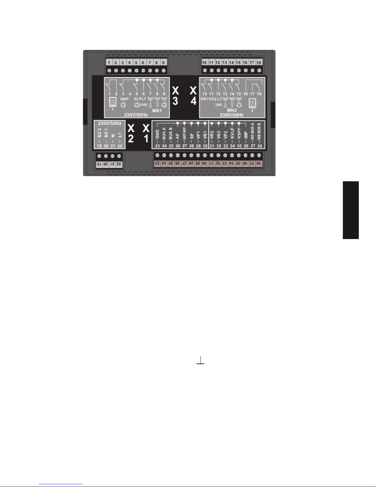
Electrical installation
The electrical connection and the further
routing to the control units is done on the
back of the unit with the four
terminal strips X1, X2, X3 and X4 in the
boiler control unit, corresponding to the
designations in the coloured terminal
fields.
The routing in the wall-mounting case is
prepared in the factory.
All terminal clamps inside the blue
fields (X1) carry low voltage and may
not get into contact with the mains
voltage! Ignoring this will inevitably
lead to the destruction of the control
unit and to the loss of the basis for
warranty claims!
The terminal clamps in the red fields
(X2...X4), depending on the operation
mode, generally carry mains voltage.
Terminal occupation, see next page.
Note:
When routing the unit, ensure that sensor, data bus- and mains lines are routed
separately. Mutual routing inside one
cable is prohibited. Sensor- and data bus
lines may not be routed with mains lines
that supply electrical units that are not
interference suppressed according to EN
60555-2.
230 V~
GB
Page 7
GB-7
Electrical connection
Mains connection
1 - Do not use
2 - Do not use
3 - Unmixed circuit pump
4 - Do not use
5 - Charge pump
6 - L 1 / 230 V
7 - Mixing valve 1 OPEN
8 - Mixing valve 1 CLOS
9 - Mixed circuit pump 1
10 - Variable output 1
11 - Variable output 2
12 - L 1 / 230 V
13 - Mixing valve 2 OPEN
14 - Mixing valve 2 CLOS
15 - Mixed circuit pump 2
16 - Do not use
17 - Do not use
18 - Do not use
19 - Do not use
20 - Do not use
21 - N / 230 V
22 - L 1 / 230 V
Sensor-/data bus connection
23 - GND for sensor
24 - Data bus connection A
25 - Data bus connection B
26 - Outside sensor ARV20 Mad
27 - Do not use
28 - Tank sensor
29 - Flow sensor mixed circuit 1
30 - Variable input 1
31 - Variable input 2
32 - Variable input 3
33 - Flow sensor mixed circuit 2
34 - Do not use
35 - Do not use
36 - Impulse input
37 - Boiler control unit-data bus A
38 - Boiler control unit-data bus B
GND for sensor
} Mains connection
GB
When building in a MadQ controller into a boiler a data bus connection is made between the
boiler and the controller through the cable loom. In case of a Cascade installation the
positions 20 and 21 of the connection block of each boiler have to be connected to each
other. Adjust Parameter 89 of each boiler to their individual bus address: Boiler 1 = 00, boiler
2 = 01, etc. See also example 17 on page XXXIV.
Page 8
GB-8
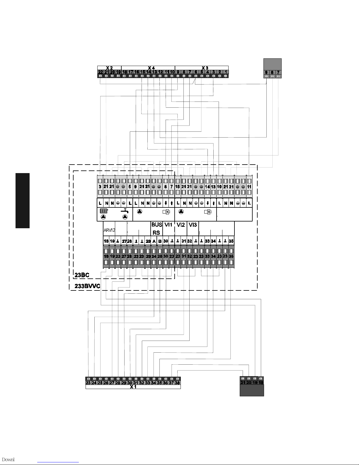
Installation set MadQ
GB
Cable harness for the installation of a control unit in the boiler control unit
MC-1 MC-2
MC-1
MC-2
Sensor
Sensor
DHW
VO1 VO2
USPSPS
OS
ARV12
Page 9

GB-9
Wall-mounting case
Application:
The wall-mounting case serves as a case
for the control unit.
Design
The wall-mounting case is only suitable for
use as a case and for the connections of
the control unit.
The control unit is ready for use after it
has been fastened to the motherboard
and after the output cables have been
routed.
Assembly and electric installation
1- Push out the cable inlets at the pre-
stamped locations at the top or bottom
according to the size and number of
the cable ducts.
Note:
If no cable duct is used, a suitable
strain relief for the cables must be
ensured during installation.
2- Place locking bolts (1) horizontally and
pull off the connection covers (2) to
one side.
3- Install the wall-mounting case with the
supplied bolts and dowel pins on a flat
surface without distorting it. Use the
enclosed drilling jig.
4- Carry out the electric routing according
to the unit version and the connection
diagram (see reverse).
The terminal clamps of the terminal
blocks X5 and X6 in the left
connection
area carry low voltage and may not
come into contact with the mains
voltage! Ignoring this will inevitably
lead to the destruction of the control
unit and to the loss of the basis for
warranty claims!
The terminal clamps of the terminal
blocks X7 to X10 in the right
connection area carry mains voltage,
depending on the operation mode.
When connecting the electric cables,
the cables with a solid core can be
placed directly into the clamp. The
twisted core must carefully be lead in
by pressing the locking device
5- Slide clamp covers onto the wall-
mounting case and fasten them.
6- Slide the control unit into the wall-
mounting unit and let it engage under
evenly distributed pressure. The
electric connection is made via the
socket strip on the motherboard.
Tighten the control unit and both quickclamping devices clockwise.
Note:
When routing the control unit, ensure that
sensor-, data bus- and mains lines are
routed separately. Mutual routing inside
one cable is prohibited. Use cable ducts
equipped with separators, if necessary.
230 V~
1
2
GB
Page 10
GB-10
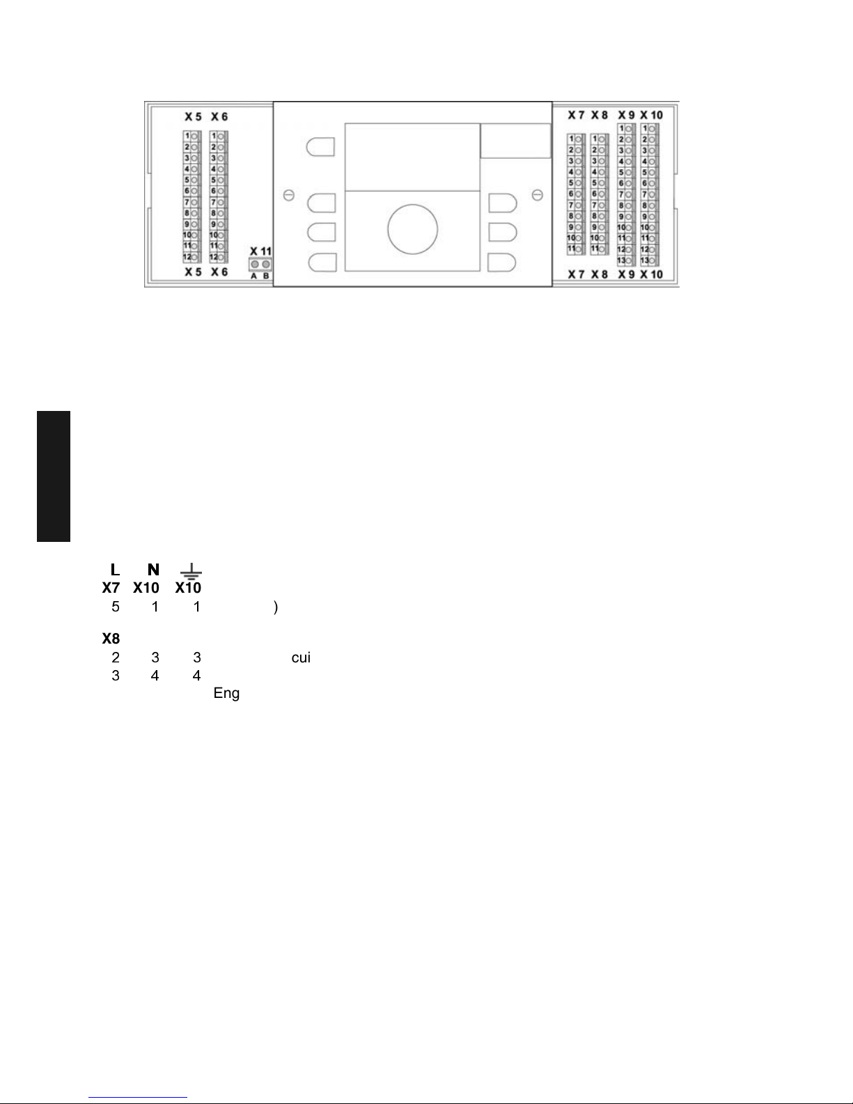
Electrical connections
X5 X6 Sensor- and data bus lines (X5-X6)
1 1 B – Data bus - A (T2B)
2 2 Outdoor sensor ARV20 Mad
3 3 Do not use
4 4 Tank sensor
5 5 Flow sensor mixed circuit 1
6 6 Variable input 1
7 7 Variable input 2
8 8 Variable input 3
9 9 Flow sensor mixed circuit 2
10 10 Do not use
11 11 Do not use
12 12 Do not use
////1
11
1
X7 X10 X10 Mains connections (X7)
L1 (230V)
X8 X9 X10 Pumps and mixing valve engines (X8, X9, X10)
Unmixed circuit pump
Charge pump
4 5 5 Engine mixing valve 1 (OPEN)
5 Engine mixing valve (CLOS)
6 7 7 Mixed circuit pump 1
7 8 8 Variable output 1
8 9 9 Variable output 2
9 10 10 Engine mixing valve 2 (OPEN)
10 Engine mixing valve 2 (CLOS)
11 12 12 Mixed circuit pump 2
X11 Data bus boiler control unit (X11)
A
Data bus boiler control unit A
B Data bus boiler control unit B
Here, only connect the first MadQ of the data bus connection!
Only connect the A-B data bus boiler control unit (RS485) of the boiler control unit after the first MadQ
control unit from position 20-21 in the boiler to position A-B on X11 in the wall-mounting case. Every
following MadQ control unit (up to 5) must be connected to the A-B data bus (T2B) from position 1 to
X6 and X5.
GB
Page 11
GB-11
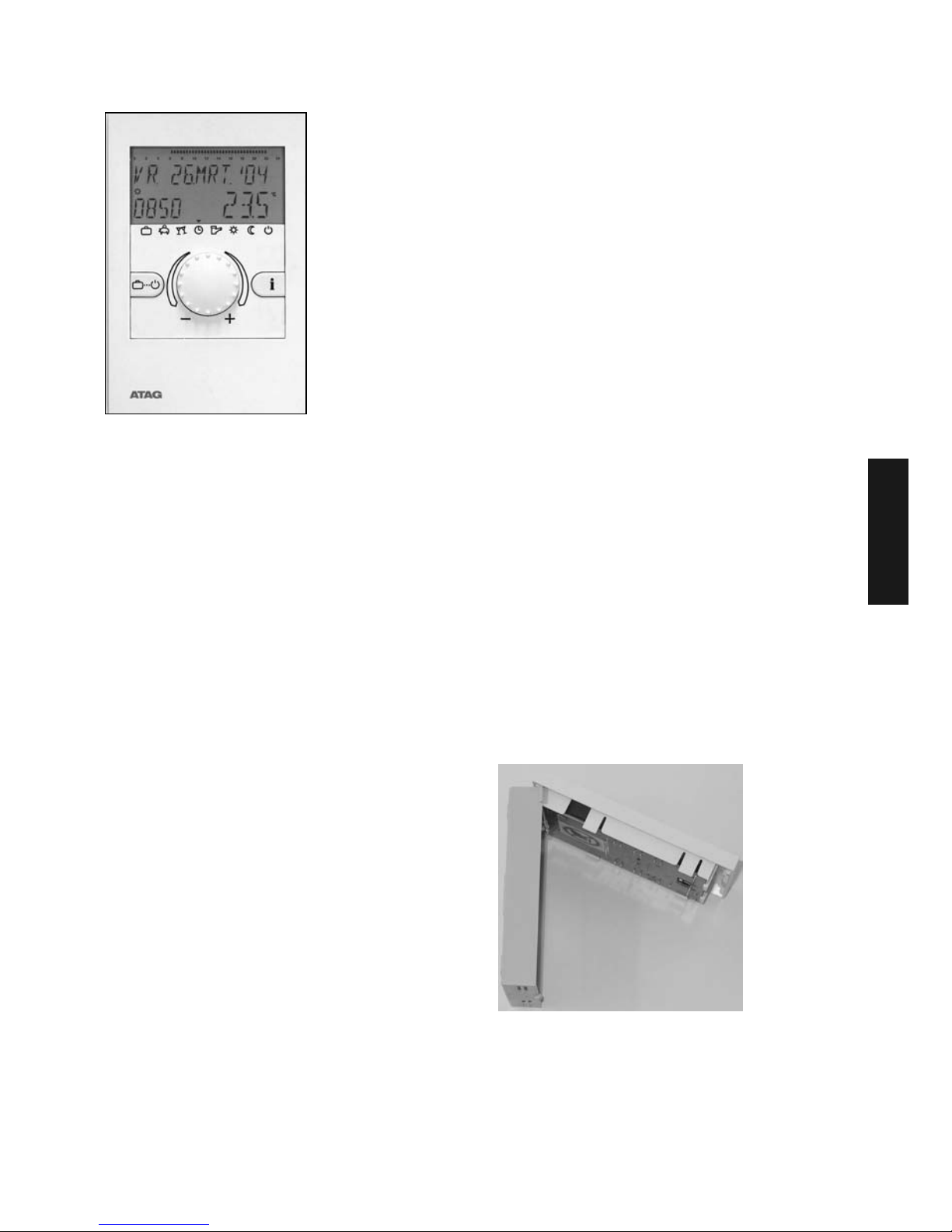
Thermostats (for remotecontrol)
Mounting Location
a – for applications without room sensor
If the internal room sensor is not to be
activated the unit may be mounted at
any location indoors.
b – for applications with room sensor
The activated room sensor should be
fixed at a height of approx.1.20 – 1.50
m at a place most representative of all
rooms. It is recommended to chose a
partition wall in the coolest day room.
In order to ensure sufficient air
circulation at the room station, it must be
mounted to the wall with a gap
inbetween.
The thermostat must not be mounted:
– at locations subjected to direct solar
radiation (consider the position of the
sun during winter).
– close to heat-generating appliances,
such as televisions, refrigerators, wall
lamps, radiators etc.
– on walls with heating or domestic hot
water pipes or chimneys behind.
– on non-insulated outside walls
– in corners or wall recesses, shelves or
behind curtains (insufficient ventilation)
– close to doors of unheated rooms
(influence of low temperatures)
– on unsealed flush-type boxes
(influence of external low temperatures
due to the chimney effect of installation
tubes)
– in rooms with radiators controlled by
thermostatic valves (mutual influence).
Mounting instructions
After removing the front panel by pressing
the locating lug the wall mounting base
can be taken off and mounted at the
desired location using the enclosed dowel
pins and screws. The data bus line must
thereby be routed through the bottom
cable gland.
Recommended connecting cable:
2x0.6 max. cable length: 50 m.
Note: For new installations use a
flush-mounting switch box to
ensure perfect routing of
cable.
↑ Locating lug
GB
Page 12

GB-12
Electrical connection
The 2-strand data bus cable is connected
to terminals A and B of the 2-pole terminal
strip on the bottom plate. The connections
are not interchangeable and must be
connected in compliance with the
identification A/B on the base. If the two
connecting lines are mixed up by mistake
the display will be out of function.
Once the electrical connection is
completed the thermostat is hooked in
flush at the top and folded down, as
shown in the picture, until it audibly
engages into the wall-mounting base.
Electrical connection at control unit
See assembly instructions of the controll
unit.
Data bus allocation
The connection of one or more
thermostats to the control unit occurs via a
two-core data bus line. Because this
connection is always carried out parallel in
the same line, a separate bus address
must be allocated to every thermostat.
Likewise, a separate bus address must be
allocated to every control unit (if there is
more than one, e.g. when the heating
circuit is extended).
Bus address (control unit)
If there is only one control unit, it should
have bus address 10. If there is more than
one control unit in the network (max.: five),
the leading control unit that controls the
boiler control unit, has bus address 10, the
others are allocated in sequence with bus
addresses 20, 30, 40 and 50.
Setting the bus address in the control
unit
The setting of the bus address is carried
out after entering the installer code in the
data bus level of the corresponding control
unit (see commissioning of the control
unit).
Bus address (thermostat)
The allocation of the bus addresses of the
control units and the bus addresses of the
thermostats must be carried out according
to the enclosed table.
Setting the bus address in the thermostat
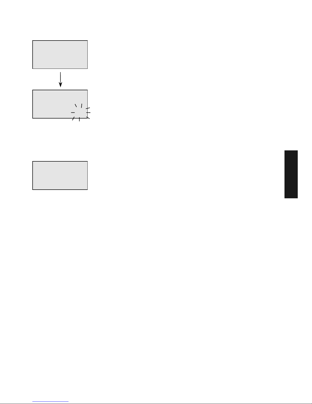
A- Commissioning
After completing the electrical installation
and commissioning the plant, all available
segments appear in the display.
Control unit Thermostat
Function
Bus
address
Heating circuit
Bus
address
Control unit 1 10
Unmixed circ.
Mixed circ. 1
Mixed circ. 2
11
12
13
Control unit 2 20
Unmixed circ.
Mixed circ. 1
Mixed circ. 2
21
22
23
Control unit 3 30
Unmixed circ.
Mixed circ. 1
Mixed circ. 2
31
32
33
Control unit 4 40
Unmixed circ.
Mixed circ. 1
Mixed circ. 2
41
42
43
Control unit 5 50
Unmixed circ.
Mixed circ. 1
Mixed circ. 2
51
52
53
¾ ¿ À Á Ä
°C
KWh
Min
%
°C
KWh
Min
%
0 2 4 6 8 10 12 14 16 18 20 22 24
Fffff
ffff
Segment test
GB
Page 13
GB-13
Subsequently, the unit identification and
the data bus address will appear.
After setting the bus address using the
rotary pushbutton and confirming this by
pressing it, the allocation determined by the
address will appear automatically.
Attention:
Double allocation of bus addresses is not
permitted and inevitably lead to faults in
data transfer and therefore to faulty control
of the heating system.
B - Changing bus addresses
If a bus address has to be changed
afterwards, then carry out the following
procedure:
1 - By pressing the bottom locking device,
remove the thermostat from the
ground board (the bus is
disconnected).
2 - Place the thermostat again while
keeping the rotary pushbutton
depressed until the address setting
appears.
3 - Set and confirm a new bus address.
RS-2
15.05.
V1.2
BUS ADDRES
11
Instrument identification
Device type
Software date
Software version
Address settings
see table above
BUS
HC
AU-1
Data bus address
Unmixed circ.
MadQ control unit 1
(=AU1),
MadQ control unit 2
(=AU2), etc.
GB
Page 14

GB-14
Accessories
Outdoor sensor
Mounting Location
The outdoor sensor should be mounted on
the most exposed and coldest side of the
building (north or north-east) at a height of
min. 2 m above ground.
Exception: If the preferential living
area is facing another
direction, the
corresponding side of
the building should be
chosen.
When mounting the sensor mind external
heat sources (heated chimneys, war hot
air from air shafts, installation on black
surfaces, thermal bridges in the wall, etc.)
which could falsify the measuring value.
The cable outlet must always be directed
downwards in order to avoid the
penetration of moisture.
The outside sensor may not be installed
close to transmitting or receiving
equipment (on garage walls close to
receivers for garage door openers,
amateur radio antennas, radio controlled
alarm systems or close to large scale
radio transmission equipment etc.).
Electrical connection
For the electrical installation preferably
use a 2-strand cable with a minimum
cross-section of 0,6mm
2
. The connection
is made at the 2 screw terminals inside the
sensor case and may be interchanged.
Mounting instructions
1– Route the sensor cable to the
mounting location
2– Loosen lid screws from sensor case
and remove top
3– Mount sensor base with enclosed
central fastening screw.
Use sealing ring! Cable outlet must be
directed downwards!
4– Insert the sensor cable so that the
cable jacket is fully enclosed by the
sealing lip.
5– Electrical connection on terminal block
boiler control unit position 18-19.
6– Attach the lid again an and screw it
firmly onto the base. Ensure correct fit
of sealing ring.
In situations when the control unit has to
be controlled via its own outside sensor,
ARV20 (white) must be used. Connection
to the control unit.
Outside sensor
ARV12
GB
Page 15

GB-15
Tank sensor
Versions:
AVB06 Cable length 5 m
Application: Tank sensor (for nearby hot
water generators, buffer
tanks etc.)
Mounting location:
In the designated immersion sleeve of the
corresponding application.
Mounting in DHW- or buffer tanks
Bend the pressing spring towards the
sensor tip and slide the sensor into the dry
immersion sleeve of the corresponding
tank.
Electrical connection
Clamp the sensor to the appropriate
terminal clamps of the respective control
unit (see corresponding connection
diagram). The two-strand connection is
interchangeable.
Flow sensor
Flow sensor VF20
Versions:
VF 20 Cable length 4 m
S4363400
Application: As a flow sensor for unmixed
circuits and mixed circuits of
heating circuits
Mounting location:
Behind the mixer pump at a distance of at
least 50 cm.
Mounting:
Polish the flow pipe and apply heat
conductive paste.
Fasten the sensor to the contact location with
a tensioning belt so that it is flush with the
pipe's surface.
Ensure a tight fitting!
Electrical connection
Clamp the sensor to the appropriate terminal
clamps of the respective control unit (see
corresponding connection diagram). The twostrand connection is interchangeable.
Tank sensor AVB06
GB
Page 16

GB-16
Resistance values of sensors
depending on temperature
temperature
°°°°Celsius
PTC 2K
(2kΩΩΩΩ/25°°°°C)
Flow sensor VF20
Outside sensor ARV20
Tank sensor AVB06
NTC 12K
(12kΩΩΩΩ/25°°°°C)
Outside sensor ARV12
-20 1.387 98.900
-18
-16
-14
-12
-10
1.413
1.438
1.463
1.488
1.513
98.950
80.100
72.200
65.150
58.900
-8
-6
-4
-2
0
1.540
1.566
1.593
1.619
1.646
53.300
48.250
43.750
39.750
36.150
2
4
6
8
10
1.673
1.700
1.728
1.756
1.783
32.900
29.950
27.350
24.950
22.800
12
14
16
18
20
1.812
1.841
1.869
1.898
1.927
20.850
19.100
17.500
16.100
14.750
22
24
26
28
30
1.957
1.986
2.016
2.046
2.077
13.600
12.500
11.500
10.600
9.800
32
34
36
38
40
2.107
2.128
2.169
2.200
2.232
9.100
8.350
7.750
7.200
6.650
45
50
2.311
2.393
5.525
4.600
55
60
2.475
2.559
3.850
3.250
70 2.732 2.325
80 2.910 1.700
90 3.093 1.275
100 3.283 950
GB
Page 17
GB-17
Commissioning the control unit
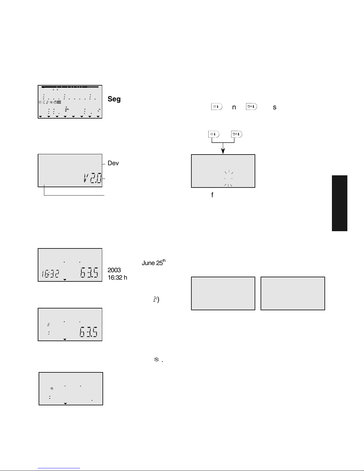
Segment test and identification
During the first activation of the control
unit or with each return of voltage after a
power failure all segments available in
display will appear:
This is followed by the equipment version
with type code and current version number
of software status
If there is no alarm at present, the
standard display with date, time and
current flow temperature will appear
afterwards.
An active summer switch-off is
represented by a sunshade symbol (À).
An active frost protection function is
represented by a ice crystal symbol (Á).
Code input
Installer code
After entering the installer code all
parameters determined for the heating
specialist are released and can be edited
in accordance with the syst version.
Code input
In order to enter the installer code, the
keys
¥
and
§
must be pressed
simultaneously for approx. three seconds,
until the code input appears in the display.
¥
+
§
Each flashing digit is set by using the
rotary pushbutton in accordance with the
code number and is confirmed by pressing
the button. All other digits are edited in the
same way.
After the code has been entered correctly,
the acknowledgement INSTALLER OK will
appear upon confirmation of the last digit,
after a wrong entry, the message CODE
ERROR will appear.
The factory set consumer code is: 1 2 3 4
The factory set installer code is : 0 1 2 3
Note: If the code is not accepted, you
should consult the supplier!
Attention: Enabled installer parameters will
be blocked again if no further
action takes place over a period of
ten minutes. In this case the
installer code must be entered
again.
¾ ¿ À Á Ä
°C
KWh
Min
%
°C
KWh
Min
%
0 2 4 6 8 10 12 14 16 18 20 22 24
Fffff
ffff
À
°C
;
1632
63.5
°C
;
1632
63.5
Segment test
Standard displa
y
Wednesday, June 25
th
2003
16:32 hrs Temp. 63.5°C
Summer shutdown
active
Á
°C
;
1632
635
Plant frost
protection
active
N
VV
18
V2.0
Device type
Version number
Type code
CODE
0
000
I
OK
GB
Page 18

GB-18
Automatic setting function
This function can switch off control circuits
that are not needed or are only needed later.
The control circuits are registered
automatically when their corresponding
sensors are connected and transfer
permitted measuring values. Control circuits
without sensor circuits are automatically
switched off without displaying an alarm.
The AUTO-SET function is activated every
time the mains voltage is switched on.
Automatic activation
If the AUTO-SET function is switched on by
parameter 14 in the SYSTEM level and the
commissioning date has not yet been saved,
then the sensors that are connected or
clamped off are registered automatically
every time the control unit is switched on.
During this period, the error messages of the
sensors (short circuit interruption) are
suppressed.
If the commissioning date was saved, a
changed sensor configuration can only be
confirmed via manual activation.
Manual activation
The AUTO-SET function can be activated
manually at any time. To do this, press the
rotary pushbutton when switching on the
control unit while the version is being
displayed. Keep the button depressed until
the AUTO-SET function in the display is quit.
The AUTO-SET function serves the following
sensor inputs:
– Outdoor sensor
– Flow sensor 1
– Flow sensor 2
– Tank sensor
Apart from that, the AUTO-SET function is
only carried out if the circuits in the following
levels that are allocated to the sensors were
parameterised accordingly.
For the tank sensor:
HYDRAULIC Level
Parameter 2 - DHW-charge pump function
set value OFF or 1 (DHW-charge pump)
For flow sensor 1:
HYDRAULIC Level
Parameter 3 – mixed circuit function 1 set
value OFF or 3 (mixed circuit)
For flow sensor 2:
HYDRAULIC Level
Parameter 4 – mixed circuit function 2 set
value OFF or 3 (mixed circuit)
Because a parameter setting is not changed
by the AUTO-SET function, the current
settings are checked beforehand. A change is
only made if one of the settings above is
changed. This means that the deeper system
configuration can never be changed by the
AUTO-SET function.
N
VV
18
V2.0
T
T
Standard display
GB
Page 19
GB-19
Alarm messages
In order to be able to perform an exact
diagnose in case of a problem the control
system is equipped with a comprehensive
fault alarm system. An alarm is thereby
always displayed and saved on the
corresponding control unit.
There are five different categories of error
messages:
1 - Sensor error messages
Sensor measuring values that are not
inside the measuring range are valued as
errors. They appear with an error message
according to their use.
2 - Error messages of the boiler control
unit
These error messages evaluate the
respective control status. They appear with
the corresponding error message,
depending on the version and allocation.
3 - Logical error messages
The error messages evaluate the expected
control result. They appear with the
corresponding error message, depending
on the version and allocation.
4 - Bus error messages
These error messages relate to address
errors such as double allocation or
unrecognised address settings inside the
data bus. They appear with the
corresponding error message, depending
on the version and allocation.
5 - Alarms from the boiler control
These error messages come from the
boiler control and are divided into
permanent faults (permanent locking) with
error code E-XX (MCBA-code) or
temporary faults (self-eliminating locking)
with fault code B-XX (MCBA-code).
The display and further processing of logical
error messages can be suppressed by a
corresponding parameter setting (see
parameter 13 – SYSTEM level – logical error
message)
Further processing of errors:
– Errors appear in the standard display of the
control
– System errors appear in the info-level at the
corresponding info-value
– If necessary, errors are transferred into the
error message level (see description below)
– At the corresponding parameter settings,
errors activate an error notification output
for connecting an optical or acoustic signal
transmitter.
– Errors are transferred to the corresponding
gateways via the data bus.
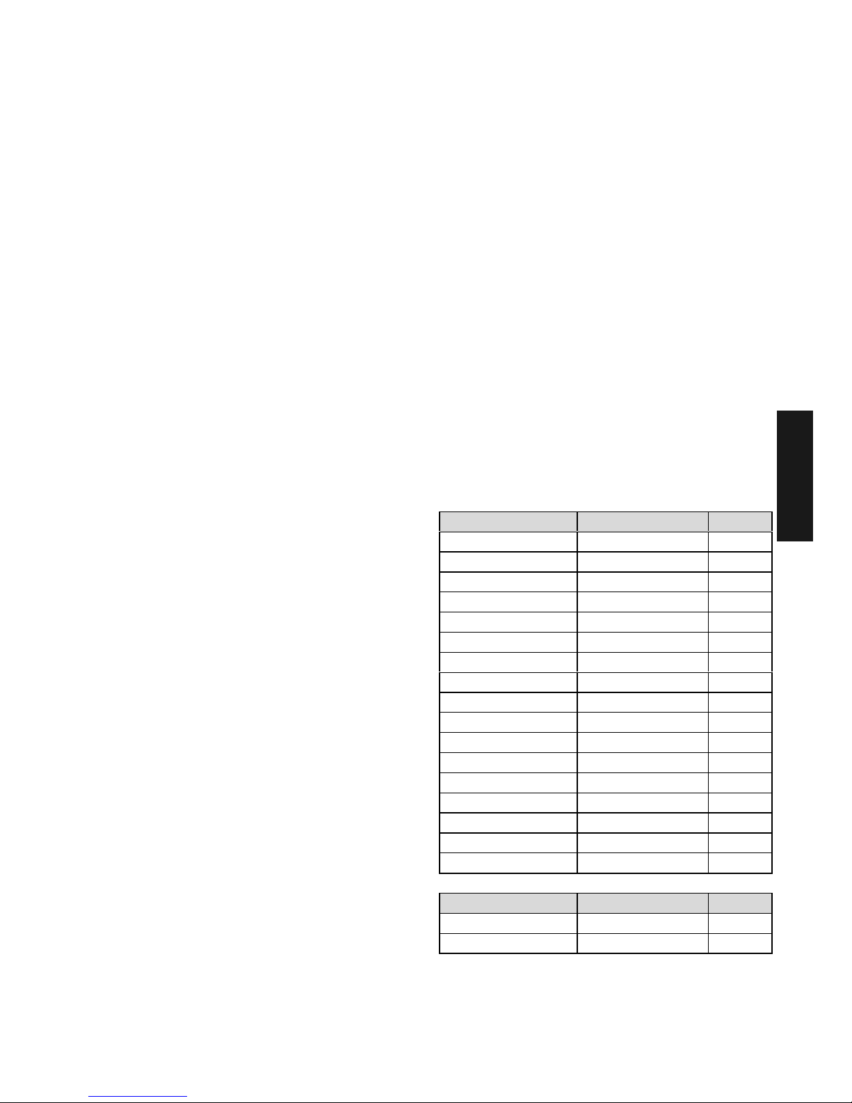
Table of error messages:
Sensors and variable inputs:
Designation Error type Code
Outdoor sensor Interruption 10-0
Outdoor sensor Short circuit 10-1
Flow sensor 1 Interruption 12-0
Flow sensor 1 Short circuit 12-1
Tank sensor Interruption 13-0
Tank sensor Short circuit 13-1
VI 2 Interruption 14-0
VI 2 Short circuit 14-1
VI 2 Error message 14-7
VI 3 Interruption 15-0
VI 3 Short circuit 15-1
VI 3 Error message 15-7
VI 1 Interruption 16-0
VI 1 Short circuit 16-1
VI 1 Error message 16-7
Buffer sensor Interruption 17-0
Buffer sensor Short circuit 17-1
Designation Error type Code
Flow sensor 2 Interruption 18-0
Flow sensor 2 Short circuit 18-1
GB
Page 20
GB-20
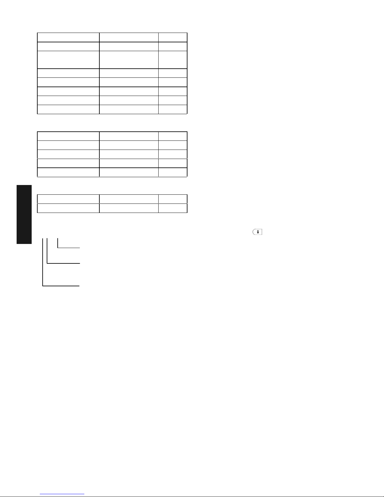
Temperatures:
Heat generator Not reached 50-4
Heat generator Exceeded 50-5
Domestic hot
water
Not reached 51-4
Flow MC1 Not reached 52-4
Flow MC2 Not reached 53-4
Room HC Not reached 54-4
ROOM MC1 Not reached 55-4
ROOM MC2 Not reached 56-4
Data bus error
Address Address conflict 70-0
Activity No T2B-signal 70-1
EEPROM 71-0
EEPROM defective 71-1
Bus error Bus error 70-6
Fault in boiler control
Error Locking En: XX
Error Blockage Bn: XX
Explanation fault in boiler control:
En: XX
Alarm message register
The control unit is provided with an error
message level, which is able to hold up to five
alarms. The alarms are displayed with date,
time, and nature of fault (error number), the
errors are polled in the sequence of their
occurrence in the level
ALARM
.
The latest (= up-to-date) alarm is prioritized at
first position, alarms that have arrived before
appear in the order of their occurrence. Upon
arrival of a new alarm the fifth alarm will be
deleted.
The alarm messages of the MCBA are a
special case. Because they are external
errors, they are not saved in the internal error
message register of the control unit.
Plant information
Plants and system temperatures
After accessing the information level using the
information key ¤ , all available plant- and
system temperatures can be requested one
by one by turning the rotary pushbutton
clockwise.
If
set value
is displayed in the following table
in the category "display value", it will appear
when the rotary pushbutton is pushed.
The following displays only appear under the
specified display conditions. Some of the
displays are not available for certain unit
versions and are therefore skipped.
GB
Boiler error codes
(see boiler documentation)
Boiler
0 = Boiler 1
1 to 7 = Boiler 2 to 8 (Cascade)
E = Error
(B =Boiler blocking code)
Page 21

GB-21
INFORMATION Display value Comments Application
Outside (1)
Mean value/
current value
Outside (1)
Min./max. value
(0.00 to 24.00 h)
Outside 2
Mean value/
current value
Outside sensor 2 to var. input
Outside 2
Min./max. value
(0.00 to 24.00 h)
Outside sensor 2 to var. input
External blockage
Blocked status
ON/OFF
Ext. blockage to VI
Tank (1)
Set value/actual
value
If there is a tank (..B..)
Tank 2
Set value/actual
value
Tank sensor 2 to var. input (..B..)
DHW-thermostat
Charge status
ON/OFF
Instead of tank sensor (..B..)
Demand via
contact point (VI-1)
Demand ON/OFF Contact to var. input
Demand via
contact point (VI-2)
Demand ON/OFF Contact to var. input
Demand via
contact point (VI-3)
Demand ON/OFF Contact to var. input
Flow
Mixed circ. 1
Set value/actual
value
(..3..)
Flow
Mixed circ. 2
Set value/actual
value
(..33..)
Room temperature
Unmixed circ.
Set value/actual
value
Control unit required (..2..)
Room temperature
Mixed circ. 1
Set value/actual
value
Control unit required (..3..)
Room temperature
Mixed circ. 2
Set value/actual
value
Control unit required (..33..)
Thermostat function
Unmixed circ.
THERMOSTAT HC
Room thermostat function active
OFF = no room limit
(..2..)
Thermostat function
Mixed circ. 1
THERMOSTAT
MC-1
Room thermostat function active
OFF = no room limit
(..3..)
Thermostat function
Mixed circ. 2
THERMOSTAT
MC-2
Room thermostat function active
OFF = no room limit
(..33..)
GB
Page 22

GB-22
Operation modes
After entering the information level using the
information key ¤ all available operating
states and usage data
such as counter readings, specified
performance data etc. can be requested one
by one by turning the rotary pushbutton anticlockwise.
Information
Example of
display
Function Application
Status
Unmixed circ.
AUTO-P1 ECO
HC ON
Program/3-program/mode
status of heating pump
(..2..)
Status
Mixed circ. 1
AUTO-P1 ECO
MC-1 ON
(..3..)
Status
of
mixing valve
Mixed circ. 1
ACTUATOR-1
OPEN
Display of set direction
OPEN-STOP-CLOS
(..3..)
Status
Mixed circ. 2
AUTO-P1 ECO
MC-2 ON
Program/3-program/mode
status of heating pump
(..33..)
Status
of
mixing valve
Mixed circ. 2
ACTUATOR-2
STOP
Display of set direction
OPEN-STOP-CLOS
(..33..)
Status of boiler
control unit stage 2
HEAT GENER.
ST-2 OFF
Switching condition
of boiler control unit
Stage 2
(..22..)
Status of boiler
control unit
(mod.)
MODULATION
57% 60%
Modulating, continuously
variable boiler control unit,
display of set and actual value
(..VV..)
Status
Tank circuit
AUTO-P1 ECO
DHW ON
Program/3-program/mode
Status of heating pump
(..B..)
Function and status
Unmixed circuit
pump
OUTPUT HC-P
EO ON
Information on the allocated
function and switching condition
of the pump
(..2..)
Function and status
Variable output 1
OUTPUT VO-1
SOP OFF
Information on the allocated
function and switching condition
of the var. output 1
(..VV..)
Function and status
Variable output 2
OUTPUT VO-2
SOP OFF
Information on the allocated
function and switching condition
of the var. output 2
(..VV..)
Explanation of the type designation
- MadQ 23BC
- MadQ 233BVVC
Application:
(2...) an unmixed circuit
(..3..) with one mixed circuit
(..33..) with two mixed circuits
(..B..) domestic hot water circuit
(..VV..) with two variable outputs
(....C) in combination with ATAG boiler control unit with an RS-485 bus.
GB
Page 23

GB-23
Parameter synoptic
Entry into the time program level: Hold rotary push-button depressed for 3 seconds - automatic call-up of time program level
Select required level with rotary pushbutton and confirm, if necessary enter code beforehand
Without colour: Directly accessible
Light gray background: accessible with code 1234
Dark gray background: accessible with code 0123
Programming Configuration Parameter settings (heating circuits, control intervals)
Parame
ter no.
Time-
Date
Time
pro-
grams
Hydrau-
lic
System
para-
meters
Domes-
tic hot
water
Unmixed
circ.
(..2..)
Mixed
circ. 1
(..3..)
Mixed
circ. 2
(..33..)
Heating
unit
(..2..)
1
TIME
(min/h)
Heat. selection
HC,MC1/2,
DHW
Installation
diagram
Language
DHW economy
temperature
Reduced
operation
Reduced
operation
Reduced
operation
Type
2 Year
Select program
P1...P3
Domestic hot
water
supply
Time
programs
Legionella
protection
(week-day)
Exponent
heating curve
Heating
system
Heating
system
3
Day-
month
Week-day
Mo...Su
Heat. cycle
(1...3)
Function MC1
Enabling
separated mode
Legionella
protection
(time)
Room sensor
display
Room sensor Room sensor
Minimum
temperature
4
Su-Wi-
timer
Switching-on
time
Function MC 2
Temperature
ECO
Legionella
protection
(temperature)
Room sensor
function
Room sensor
function
Room sensor
function
Maximum
temperature
5 Switch-off time Function HC
System frost
protection
Signal source
Heating curve
adaptation
Heating curve
adaptation
Heating curve
adaptation
6
Room / dhw
temperature
Function VO1
Heat demand
VI-1
DHW-
maximum limit
Inrush
optimization
Inrush
optimization
Inrush
optimization
7 Function VO 2
Heat demand
VI-2
DHW
programs
8 Function VI -1
Heat demand
VI-3
Cool down
protection
Room frost
protection
temperat ure
Room frost
protection
temperat ure
Room frost
protection
temperat ure
9 Function VI 2 Climate zone DHW-Tset
Exceeding
room
temperature
Exceeding
room
temperature
Exceeding
room
temperature
10 Function VI 3
Type of
building
DHW-
switching
difference
Allocation
outside sensor
Allocation
outside sensor
Allocation
outside sensor
11
minimu m
boiler return flow
temperature
Back to
standard
display
DHW-charge
pump
Constant
control
Constant
control
Constant
control
12 Forced control
Program charge
pump
Minimum flow
temperature
Minimum flow
temperature
Minimum flow
temperature
13
Logical error
messages
Economy interval
charge pump
Maximum flow
temperature
Maximum flow
temperature
Maximum flow
temperature
14 Auto SET Cycle AUP Temp. rise Tset Temp. rise Tset Temp. rise Tset
15
Reset to
factory values
Pump after-run
(HCP)
Pump after-run
(MC1-P)
Pump after-run
(MC2-P)
16
DHW basic
temperature
Screed
function
Screed
function
Screed
function
17
Maximum
return flow
temperature
Maximum
return flow
temperature
18
19
20
21
22
23
24
25
Set
temperature
day
Set
temperature
day
Set
temperature
day
26
Set
temperature
night
Set
temperature
night
Set
temperature
night
27
Heating curve
slope
Heating curve
slope
Heating curve
slope
28
GB
Page 24

GB-24
Parameter settings
Communication
Service
Buffer tank
(..VV..)
Cascade
Data bus
Relay test
Error
Sensor
adjustment
Parameter
no.
Minimum temperature Switching difference AU- Bus address Unit Alarm 1 Outdoor sensor 1
Maximum
temperature
Inrush
delay
Bus rights
RS HC
Pump
Unmixed circ.
Alarm 2 Boiler sensor 2
Temperature rise
Tset
Switch off delay
Bus rights
RS MC-1
Pump
Mixed circ. 1
Alarm 3 Tank sensor 3
Switching difference
Maximum capacity for
connection
Bus rights
RS MC-2
dwk-engine
Mixed circ. 1
Alarm 4
Flow sensor mixed
circuit 1
4
Heat dissipation Boiler order
Pump
Mixed circ. 2
Alarm 5
Flow sensor mixed
circuit 2
5
Switching on
difference
Leading boiler
dwk-engine
Mixed circ. 2
6
Switching off
difference
DHW
Charge pump
7
Starting protection Output VO-1 Sensor VI-1 8
Discharge protection Output VO-2 Sensor VI-2 9
op. mode Sensor VI-3 10
11
12
13
14
15
16
17
18
19
20
21
22
23
24
25
26
27
28
GB
Page 25

GB-25
Overview of installer parameters and adjustment options
HYDRAULIC Level
The parameters of this level refer to the general hydraulic system of the heating plant as
well as to the functionality and configuration of the programmable inputs and outputs for
the corresponding plant components.
PARA-
METER
Designation Setting range / Setting values
Factory
setting
Individual
setting
From
code
01 Installation diagram 0000, .... 9999 0 0123
02 Function assignment of
domestic hot water supply
OFF Off
1On
4 DHW-circulation pump
5 No function
1 0123
03 Function of output
mixed circuit 1
(Type ..3..)
OFF Off
2 Unmixed circ.
3 Mixed circuit
6 Constant temperature
7 No function
8 No function
3 0123
04 Function of output
mixed circuit 2
(Type .0,33..)
Setting range and allocation as for parameter
03 3 0123
05 Function of unmixed circuit OFF Off
2 Unmixed circuit pump
4 DHW-circulation pump
5 No function
6 Constant control
10 Transport pump
11 Boiler pump 1
12 Boiler pump 2
13 Error output
14 Timer
15 No function
2 0123
06 Function of variable output 1
(Type ..VV..)
OFF Off
4 DHW-circulation pump
5 No function
9 Bypass pump
10 Transport pump
11 Boiler pump 1
12 Boiler pump 2
13 Error output
15 No function
16 No function
17 No function
18 No function
19 No function
20 No function
OFF 0123
07 Function of variable output 2
(Type ..VV..)
Setting range and allocation as for parameter
06
OFF 0123
08 Function of variable input 1 OFF Off
1 Outside sensor 2
2 No function
3 Tank sensor 2
4 No function
5 On/Off-contact
6 No function
7 No function
8 No function
9 No function
10 No function
11 No function
12 No function
13 Common flow sensor
14 No function
15 No function
16 No function
17 No function
18 No function
19 No function
OFF 0123
GB
Note:No function = in preparation
Page 26

GB-26
09
Function of variable
input 2
(Type ..VV.. )
Setting range and allocation as for parameter
08 OFF 0123
10
Function of variable input 3
(Type ..VV.. )
Setting range and allocation as for parameter
08
OFF 0123
11 Minimum boiler return flow
temperature
OFF, ON
OFF 0123
SYSTEM Level
The parameters in this level refer to the general limiting parameters and setting values in
the heating system to be used.
PARA-
METER
Designation Setting range / Setting values
Factory
setting
Individual
setting
From
code
01
Language NL Dutch
GB English
F French
I Italian
NL 1234
02
Time programs P1 a time program is enabled
P1-P3 Three time programs enabled
P1 1234
03
Enabling of separate control
mode setting
1 Common adjustment for DHW-
/burner-circuits
2 Separate setting for each
individual heating circuit
1 1234
04 Summer shutdown OFF no function
10-30 °C
20 °C 1234
05 System frost protection OFF no function
-20...+10 °C
3 °C 0123
06 Heat demand on VI1 1 Mixed circ. 1
2 Mixed circ. 2
3 Unmixed circ.
1 0123
07 Heat demand on VI2 (Type
..VV..)
Settings see parameter 06
1 0123
08 Heat demand on VI3 (Type
..VV..)
Settings see parameter 06
1 0123
09 Climate zone -20.0.000.0°C -12 °C 0123
10 Type of building 1 light construction
2 medium construction
3 heavy construction
2 0123
11 Time for automatic exit OFF no
0,5...5 after set time
min Return to standard display
2 min 1234
12 24h cycle pump three way
valve
ON active
OFF inactive
ON 0123
13 Logical error messages OFF no display
ON Display active
OFF 0123
14 Automatic setting function OFF automatic error allocation
deactivated
ON automatic error allocation
activated
ON 0123
PARA
RESET
Resetting the parameter
settings
in dependence on access code only to
released parameters
GB
Page 27

GB-27
DHW level
This level contains all parameters which are necessary to program the DHW circuit with the
exception of the DHW time programs.
PARA-
METER
Designation Setting range / Setting values
Factory
setting
Individual
setting
From
code
01
DHW economy temperature 10 °C ... DHW – normal temperature
20 °C
1234
02
DHW legionella protection day
OFF No legionella protection
Mo...Su Legionella protection on the specified
weekday
ALL Legionella protection every weekday
Mo
1234
03 DHW legionella protection -
time
00:00...23:50 o'clock
02:00
0123
04 DHW legionella protection -
temperature
10 °C ... DHW maximum temperature
65 °C
0123
05 DHW – signal source
1 DHW-sensor
2 DHW-thermostat (on/off)
1
0123
06 DHW- maximum temperature
limit
20 °C ... Heat generator temperature
65 °C 0123
07
DHW programs 1 Parallel operation
2 Priority operation
3 Limited priority
4 Weather dependent parallel
operation
5 Priority operation with intermediate
heating
6 Operation with circulation valve
(priority)
7 External operation
2
0123
08
DHW tank
cool down protection (only for
charge pump)
OFF - No cool down protection
ON - Cool down protection
activated
ON
0123
09
DHW-Tset temperature rise 0 ... 50 K;
Difference between DHW-Tset temperature
and DHW set temperature
15 K
0123
10
DHW Differential 2 ... 20 K;
Value of DHW differential, symmetrical to the
DHW set temperature
5 K
0123
11
DHW-charge pump 0 ... 60 min
5 min 0123
12
Program charge pump AUTO - Active DHW-time program
1 - Action with P1, unmixed circuit
2 - Active P2, unmixed circuit
3 - Active P3, unmixed circuit
4 - Active P1, mixed circuit 1
5 - Active P2, mixed circuit 1
6 - Active P3, mixed circuit 1
7 - Active P1, mixed circuit 2
8 - Active P2, mixed circuit 2
9 - Active P3, mixed circuit 2
10 - Active P1, DHW circuit
11 - Active P2, DHW circuit
12 - Active P3, DHW circuit
AUTO
0123
13
Charge pump-economy
interval (pause)
0 min ... Setting parameter 14;
duration of shutdown time of charge
pump)
5 min
0123
14
Charge pump-economy
interval (duration)
10... 60 min
Duration = shutdown time + operating time
20 min
0123
16
DHW basis temperature +10 – DHW max. °C
63
1234
GB
Page 28

GB-28
Level UNMIXED CIRC
MIXED CIRC 1
MIXED CIRC 2
This level contains all necessary parameters for the programming of the heating circuits (mixed or
unmixed) with the exception of the time programs.
Unmixed circuit (..2..) Mixed circuit 1 (..3..) Mixed circuit 2 (.0,33..)
PARA-
METER
Designation Setting range / Setting values
Factory
setting
Individual
setting
From
code
01
Reduced operation ECO - Nightly shutdown
RED - Nightly set back
RED
1234
02
Heating curve exponent
1,00 ... 10,00
HC =1,30
MC =1,10
0123
03
Room sensor display OFF Temperature display
1 Room sensor display activated
2 Room sensor display activated,
thermostat operation blocked
3 Like OFF - with room
temperature display
1
1234
04
Room factor OFF 100% weather-dependent
10...500% Room factor (RS)
RC PI-room control + influence
Outside temperature (RS)
RC
1234
05
Heating curve adaptation OFF, ON
ON
1234
06
Inrush optimization OFF, 1 ... 8 h
1
1234
08
Room frost protection temperat
ure
5 ... 30 °C
10 °C
0123
09
Exceeding room temperature OFF, 1 ... 5 K
1
0123
10
Outside sensor allocation
(only for extra Mad outside
sensor)
0 Control according to mean value
BU 1 + BU 2
1 Control according to BU 1
2 Control according to BU 2
0
0123
11
Constant temperature 10 ... 95 °C;
Only if output is set to constant control
20 °C
0123
12
Minimum flow temperature 10 °C ... Set value maximum temperature
(parameter 13)
20 °C
0123
13
Maximum flow temperature Set value minimum temperature
(parameter 12) ... 95 °C
HC=85°C
MC=70° C
0123
14
Temperature rise
Tset
heating circuits
0 ... 20 K
HC=0
MC=4
0123
15
Pump after-run 0 ... 60 min
5 min
0123
16
Screed function
(only possible when DHW-supply
is switched off)
OFF switched off
1 heating: 3 days at 25°C, then 4
days at maximum flow
temperature
2 Heating: 1st day at 25°C, then
5K/day more up to max. flow
temperature, then 5K/day less
until 25°C
3 Heat as for 2 except 10 days
constantly on max. flow
temperature.
OFF
0123
17
1)
Maximum return flow
tempertaure Mad (..F..)
10 ... 90 °C
90 °C
0123
25
Set day temperature 5-30°C
21
1234
26
Set temperature night 5-30°C
16
1234
27
Heating curve slope
0,2 - 3,5
HC 1,75
MC1.5
1234
1)
only for mixed circuits
GB
Page 29

GB-29
DHW level (..2.. and no ..F..)
The parameters in this level refer to the mode of the corresponding heat generator and the
corresponding specific control functions.
PARA-
METER
Designation Setting range / Setting values
Factory
setting
Individual
setting
From
code
01
Version of boiler type
OFF without heat generator
Stand-alone control unit
1 Oil/gas single stage
2 Oil/gas two-stage (..22..)
3 Oil/gas 2x single stage (..22..)
5 ATAG boiler control units
(..C..)
5
0123
03
Minimum temperature
5 °C
... Maximum temperature
5 °C 0123
04
Maximum temperature
Minimum temperature ... 95 °C
80 °C 0123
BUFFER level (..VV..)
The parameters in this level refer to the special settings for buffer control. The enabling
only occurs after a correpsonding activation in the HYDRAULIC level.
PARA-
METER
Designation Setting range / Setting values
Factory
setting
Individual
setting
From code
01 Minimum temperature 5 °C ... Maximum temperature
20 °C
0123
02 Maximum temperature Minimum temperature ... 95 °C
80 °C
0123
03 Temperature rise Tset 0 ... 20 K 8 K 0123
04 Switching difference 1 ... 20 K 2 K 0123
05 Heat dissipation OFF
1 In extra buffer
2 In heating circuits
OFF 0123
06 Switching on difference (Switching off difference + 2 K) ... 30 K 10 K 0123
07 Switching off difference 1 K ... (Switching on difference -2 K) 5 K 0123
08 Starting protection OFF no starting protection
ON Starting protection active
ON 0123
09 Discharge protection OFF no discharge protection
ON Discharge protection active
ON 0123
10 Buffer program 1 Charging control for HC and DHW
2 Charging control for HC without
DHW
3 Discharging control for HC and
DHW
4 Discharging control for HC without
DHW
5 Charging control with changeover
DHW
6 Discharging control to the unit
1 0123
GB
Page 30

GB-30
CASCADE Level
The parameters in this level refer to cascaded boiler control unit in the network (e.g.
multiple boiler plants) and are only accessible in the first central control unit with bus
address 10.
PARAMETER
Designation Setting range / Setting values
Factory
setting
Individual
setting
From code
01
Switching difference 6.0...30.0 K 8 K
0123
02
Switch-on delay 0..0.60 min
0 min
0123
03
Switch off delay 0..0.60 min
0 min
0123
04
Maximum capacity for
connection
10...100%
40%
0123
05
Boiler order OFF, 1...240 h 250
0123
06
Leading boiler 1...n
1
0123
DATA BUS Level
The parameters in this level exclusively refer to the parameters that are conntected tot he
data bus.
PARAMETER
Designation Setting range / Setting values
Factory
setting
Individual
setting
From code
01
Bus address MadQ control
unit
10, 20, 30, 40, 50
10
0123
02 Bus rights RS HC
1 Janitor status
2 Tenent status
2
0123
03 Bus rights RS MC-1
3 Janitor status
4 Tenent status
2
0123
04 Bus rights RS MC-2
1 Janitor status
2 Tenent status
2
0123
RELAY TEST Level
In this level, the relays inside the control unit can be selected and their function checked
using the rotary pushbutton.
PARAMETER
Designation Setting range / Setting values
Factory
setting
Individual
setting
From code
01 Test unit
On/Off
OFF
0123
02 Test pump unmixed circuit
OFF-ON-OFF-...
OFF
0123
03 Test mixed circuit pump 1
OFF-ON-OFF-...
OFF
0123
04 Test dwk-engine
mixed circuit 1
STOP-OPEN-STOP-CLOS-STOP...
STOP
0123
05
Test mixed circuit pump 2
OFF-ON-OFF-...
OFF
0123
06
Test dwk-engine
mixed circuit 2
STOP-OPEN-STOP-CLOS-STOP...
STOP
0123
07 Test charge pump OFF-ON-OFF-...
OFF
0123
08 Test variable output1 OFF-ON-OFF-...
OFF
0123
09 Test variable output 2 OFF-ON-OFF-...
OFF
0123
GB
Page 31

GB-31
ALARM MESSAGE Level
In this level up to five alarm messages can be stored, these are permanently updated.
PARAMETER
Designation Setting range / Setting values
Factory
setting
Individual
setting
From code
01 Alarm 1 Last alarm message 0123
02 Alarm 2 Alarm message before last 0123
03 Alarm 3 Third to last alarm message 0123
04 Alarm 4 Fourth to last alarm message 0123
05
Alarm 5 Fifth to last alarm message 0123
SENSOR CALIBRATION Level
In this level all sensors connected to the central control unit can be corrected by ± 5 K with
respect to the factory settings.
PARAMETER
Designation Setting range / Setting values
Factory
setting
Individual
setting
From code
01 Outside temperature
adaptation
- 5 K ... +5 K
0
0123
02 No function
03 Compensation tank sensor
- 5 K ... +5 K
0
0123
04 Compensation flow sensor 1
- 5 K ... +5 K
0
0123
05
Compensation flow sensor 2 - 5 K ... +5 K
0
0123
06
No function
07
No function
08
Compensation variable input 1 - 5 K ... +5 K
0
0123
09
Compensation variable input 2 - 5 K ... +5 K
0
0123
10
Compensation variable input 3 - 5 K ... +5 K
0
0123
GB
Page 32

GB-32
Notes
GB
Page 33

I
Appendix
Appendix
Appendice
Appendice
Page 34

II
Voorbeeld 1
Opgelet!
Alleen principiële schema – geen uitvoeringsplan!
Exemple 1
Attention !
Seulement schéma de principe -Pas de plan d'exécution !
Example 1
Important!
This is only a basic schematic – Do not use for installation!
Esempio 1
Attenzione!
Solo schema di massima - non è il disegno di esecuzione!
Page 35

III
Regeling met MadQ 23BC inbouw met
1 Directe groep weersafhankelijk
1 Menggroep weersafhankelijk
A
Toestel
4
Buitenvoeler9Cascade-/menggroepregelaar10Kabelboom C/M-regelaar
C
1
Ruimteregelaar (optie)2Aanvoervoeler5Drieweg(meng)klep6Pomp
Control unit with built-in Mad Q 23BC with
1 unmixed circuit, weather controlled
1 mixed circuit, weather controlled
A
Unit
4
Outdoor sensor9Cascade-/mixed circuit control unit10Cable harness C/M-control unit
C
1
Room control unit (optional)2Flow sensor5Threeway (mix) valve6Pump
Page 36

IV
Voorbeeld 2
Opgelet!
Alleen principiële schema – geen uitvoeringsplan!
Exemple 2
Attention !
Seulement schéma de principe -Pas de plan d'exécution !
Example 2
Important!
This is only a basic schematic – Do not use for installation!
Esempio 2
Attenzione!
Solo schema di massima - non è il disegno di esecuzione!
Page 37

V
Regeling met MadQ 23BC inbouw met
Open verdeler
1 Directe groep met ruimteregeling
1 Menggroep weersafhankelijk
A
Toestel
0
Contactstrip4Buitenvoeler9Cascade-/menggroepregelaar10Kabelboom C/M-regelaar
C
1
Ruimteregelaar6Pomp
D
1
Ruimteregelaar (optie)2Aanvoervoeler5Drieweg(meng)klep6Pomp
Control unit with built-in Mad Q 23BC with
Open distributor
1 unmixed circuit with room control
1 mixed circuit, weather controlled
A
Unit
0
Terminal strip4Outdoor sensor9Cascade-/mixed circuit control unit10Cable harness C/M-control unit
C
1
Room control unit6Pump
D
1
Room control unit (optional)2Flow sensor5Threeway (mix) valve6Pump
Page 38

VI
Voorbeeld 3
Opgelet!
Alleen principiële schema – geen uitvoeringsplan!
Exemple 3
Attention !
Seulement schéma de principe -Pas de plan d'exécution !
Example 3
Important!
This is only a basic schematic – Do not use for installation!
Esempio 3
Attenzione!
Solo schema di massima - non è il disegno di esecuzione!
Page 39

VII
Regeling met MadQ 23BC inbouw met
1 Directe groep met ruimteregeling
1 Menggroep weersafhankelijk
1 Boiler
A
Toestel
0
Contactstrip4Buitenvoeler9Cascade-/menggroepregelaar10Kabelboom C/M-regelaar
B3
Boilervoeler5Drieweg(meng)klep
C1
Ruimteregelaar
D1
Ruimteregelaar (optie)2Aanvoervoeler5Drieweg(meng)klep6Pomp
Control unit with built-in Mad Q 23BC with
1 unmixed circuit with room control
1 mixed circuit, weather controlled
1 tank
AUnit
0
Terminal strip4Outdoor sensor9Cascade-/mixed circuit control unit10Cable harness C/M-control unit
B3
Tank sensor5Threeway (mix) valve
C1
Room control unit
D1
Room control unit (optional)2Flow sensor5Threeway (mix) valve6Pumpe
Page 40

VIII
Voorbeeld 4
Opgelet!
Alleen principiële schema – geen uitvoeringsplan!
Exemple 4
Attention !
Seulement schéma de principe -Pas de plan d'exécution !
Example 4
Important!
This is only a basic schematic – Do not use for installation!
Esempio 4
Attenzione!
Solo schema di massima - non è il disegno di esecuzione!
Page 41

IX
Regeling met MadQ 23BC inbouw met
Open verdeler
1 Directe groep met ruimteregeling
1 Menggroep weersafhankelijk
1 Boiler
A
Toestel
0
Contactstrip4Buitenvoeler9Cascade-/menggroepregelaar10Kabelboom C/M-regelaar
B
3
Boilervoeler5Drieweg(meng)klep
C
1
Ruimteregelaar6Pomp
D
1
Ruimteregelaar (optie)2Aanvoervoeler5Drieweg(meng)klep6Pomp
Control unit with built-in Mad Q 23BC with
Open distributor
1 unmixed circuit with room control
1 mixed circuit, weather controlled
1 tank
A
Unit
0
Terminal strip4Outdoor sensor9Cascade-/mixed circuit control unit10Cable harness C/M-control unit
B
3
Tank sensor5Threeway (mix) valve
C
1
Room control unit6Pump
D
1
Room control unit (optional)2Flow sensor5Threeway (mix) valve6Pump
Page 42

X
Voorbeeld 5
Opgelet!
Alleen principiële schema – geen uitvoeringsplan!
Exemple 5
Attention !
Seulement schéma de principe -Pas de plan d'exécution !
Example 5
Important!
This is only a basic schematic – Do not use for installation!
Esempio 5
Attenzione!
Solo schema di massima - non è il disegno di esecuzione!
Page 43

XI
Regeling met MadQ 23BC inbouw met
1 Directe groep met ruimteregeling
1 Menggroep weersafhankelijk
1 Boiler
A
Toestel
0
Contactstrip4Buitenvoeler5Drieweg(meng)klep9Cascade-/menggroepregelaar10Kabelboom C/M-regelaar
B
3
Boilervoeler
C
1
Ruimteregelaar
D
1
Ruimteregelaar (optie)2Aanvoervoeler5Drieweg(meng)klep6Pomp
Control unit with built-in Mad Q 23BC with
1 unmixed circuit with room control
1 mixed circuit, weather controlled
1 tank
A
Unit
0
Terminal strip4Outdoor sensor5Threeway (mix) valve9Cascade-/mixed circuit control unit10Cable harness C/M-control unit
B
3
Tank sensor
C
1
Room control unit
D
1
Room control unit (optional)2Flow sensor5Threeway (mix) valve6Pump
Page 44

XII
Voorbeeld 6
Opgelet!
Alleen principiële schema – geen uitvoeringsplan!
Exemple 6
Attention !
Seulement schéma de principe -Pas de plan d'exécution !
Example 6
Important!
This is only a basic schematic – Do not use for installation!
Esempio 6
Attenzione!
Solo schema di massima - non è il disegno di esecuzione!
Page 45

XIII
Regeling met MadQ 23BC inbouw met
Open verdeler
1 Directe groep met ruimteregeling
1 Menggroep weersafhankelijk
1 Boiler
A
Toestel
0
Contactstrip4Buitenvoeler5Drieweg(meng)klep9Cascade-/menggroepregelaar10Kabelboom C/M-regelaar
B3
Boilervoeler
C1
Ruimteregelaar6Pomp
D1
Ruimteregelaar (optie)2Aanvoervoeler5Drieweg(meng)klep6Pomp
Control unit with built-in Mad Q 23BC with
Open distributor
1 unmixed circuit with room control
1 mixed circuit, weather controlled
1 tank
A
Unit
0
Terminal strip4Outdoor sensor5Threeway (mix) valve9Cascade-/mixed circuit control unit10Cable harness C/M-control unit
B3
Tank sensor
C1
Room control unit6Pump
D1
Room control unit (optional)2Flow sensor5Threeway (mix) valve6Pump
Page 46

XIV
Voorbeeld 7
Opgelet!
Alleen principiële schema – geen uitvoeringsplan!
Exemple 7
Attention !
Seulement schéma de principe -Pas de plan d'exécution !
Example 7
Important!
This is only a basic schematic – Do not use for installation!
Esempio 7
Attenzione!
Solo schema di massima - non è il disegno di esecuzione!
Page 47

XV
Regeling met MadQ 23BC inbouw met
Open verdeler
1 Directe groep met ruimteregeling
1 Menggroep weersafhankelijk
1 Boilerpomp
A
Toestel
0
Contactstrip4Buitenvoeler9Cascade-/menggroepregelaar10Kabelboom C/M-regelaar
B
3
Boilervoeler6Pomp
C
1
Ruimteregelaar6Pomp
D
1
Ruimteregelaar (optie)2Aanvoervoeler5Drieweg(meng)klep6Pomp
Control unit with built-in Mad Q 23BC with
Open distributor
1 unmixed circuit with room control
1 mixed circuit, weather controlled
1 heating pump
A
Unit
0
Terminal strip4Outdoor sensor9Cascade-/mixed circuit control unit10Cable harness C/M-control unit
B
3
Tank sensor6Pump
C
1
Room control unit6Pump
D
1
Room control unit (optional)2Flow sensor5Threeway (mix) valve6Pump
Page 48

XVI
Voorbeeld 8
Opgelet!
Alleen principiële schema – geen uitvoeringsplan!
Exemple 8
Attention !
Seulement schéma de principe -Pas de plan d'exécution !
Example 8
Important!
This is only a basic schematic – Do not use for installation!
Esempio 8
Attenzione!
Solo schema di massima - non è il disegno di esecuzione!
Page 49

XVII
Regeling met MadQ 23BC wandopbouw met
1 Directe groep weersafhankelijk
1 Menggroep weersafhankelijk
A
Toestel
0
Contactstrip4Buitenvoeler9Cascade-/menggroepregelaar11Wandopbouwkast C/M-regelaar
C
1
Ruimteregelaar
D
1
Ruimteregelaar (optie)2Aanvoervoeler5Drieweg(meng)klep6Pomp
Control unit with Mad Q 23BC (wall-mounting) with
1 unmixed circuit, weather controlled
1 mixed circuit, weather controlled
A
Unit
0
Terminal strip4Outdoor sensor9Cascade-/mixed circuit control unit11Wall-mounting case C/M-control unit
C
1
Room control unit
D
1
Room control unit (optional)2Flow sensor5Threeway (mix) valve6Pump
Page 50

XVIII
Voorbeeld 9
Opgelet!
Alleen principiële schema – geen uitvoeringsplan!
Exemple 9
Attention !
Seulement schéma de principe -Pas de plan d'exécution !
Example 9
Important!
This is only a basic schematic – Do not use for installation!
Esempio 9
Attenzione!
Solo schema di massima - non è il disegno di esecuzione!
Page 51

XIX
Regeling met MadQ 23BC wandopbouw met
1 Directe groep met ruimteregeling
1 Menggroep weersafhankelijk
A
Toestel
0
Contactstrip4Buitenvoeler9Cascade-/menggroepregelaar11Wandopbouwkast C/M-regelaar
C
1
Ruimteregelaar
D
1
Ruimteregelaar (optie)2Aanvoervoeler5Drieweg(meng)klep6Pomp
Control unit with Mad Q 23BC (wall-mounting) with
1 unmixed circuit with room control
1 mixed circuit, weather controlled
A
Unit
0
Terminal strip4Outdoor sensor9Cascade-/mixed circuit control unit11Wall-mounting case C/M-control unit
C
1
Room control unit
D
1
Room control unit (optional)2Flow sensor5Threeway (mix) valve6Pump
Page 52

XX
Voorbeeld 10
Opgelet!
Alleen principiële schema – geen uitvoeringsplan!
Exemple 10
Attention !
Seulement schéma de principe -Pas de plan d'exécution !
Example 10
Important!
This is only a basic schematic – Do not use for installation!
Esempio 10
Attenzione!
Solo schema di massima - non è il disegno di esecuzione!
Page 53

XXI
Regeling met MadQ 23BC wandopbouw met
Open verdeler
1 Directe groep met ruimteregeling
1 Menggroep weersafhankelijk
A
Toestel
0
Contactstrip4Buitenvoeler9Cascade-/menggroepregelaar11Wandopbouwkast C/M-regelaar
C
1
Ruimteregelaar6Pomp
D
1
Ruimteregelaar (optie)2Aanvoervoeler5Drieweg(meng)klep6Pomp
Control unit with Mad Q 23BC (wall-mounting) with
Open distributor
1 unmixed circuit with room control
1 mixed circuit, weather controlled
A
Unit
0
Terminal strip4Outdoor sensor9Cascade-/mixed circuit control unit11Wall-mounting case C/M-control unit
C
1
Room control unit6Pump
D
1
Room control unit (optional)2Flow sensor5Threeway (mix) valve6Pump
Page 54

XXII
Voorbeeld 11
Opgelet!
Alleen principiële schema – geen uitvoeringsplan!
Exemple 11
Attention !
Seulement schéma de principe -Pas de plan d'exécution !
Example 11
Important!
This is only a basic schematic – Do not use for installation!
Esempio 11
Attenzione!
Solo schema di massima - non è il disegno di esecuzione!
Page 55

XXIII
Regeling met MadQ 23BC wandopbouw met
Open verdeler
1 Directe groep met ruimteregeling
1 Menggroep weersafhankelijk
1 Boiler
A
Toestel
0
Contactstrip4Buitenvoeler5Drieweg(meng)klep9Cascade-/menggroepregelaar11Wandopbouwkast C/M-regelaar
B
3
Boilervoeler
C
1
Ruimteregelaar6Pomp
D
1
Ruimteregelaar (optie)2Aanvoervoeler5Drieweg(meng)klep6Pomp
Control unit with Mad Q 23BC (wall-mounting) with
Open distributor
1 unmixed circuit with room control
1 mixed circuit, weather controlled
1 tank
A
Unit
0
Terminal strip4Outdoor sensor5Threeway (mix) valve9Cascade-/mixed circuit control unit11Wall-mounting case C/M-control unit
B
3
Tank sensor
C
1
Room control unit6Pump
D
1
Room control unit (optional)2Flow sensor5Threeway (mix) valve6Pump
Page 56

XXIV
Voorbeeld 12
Opgelet!
Alleen principiële schema – geen uitvoeringsplan!
Exemple 12
Attention !
Seulement schéma de principe -Pas de plan d'exécution !
Example 12
Important!
This is only a basic schematic – Do not use for installation!
Esempio 12
Attenzione!
Solo schema di massima - non è il disegno di esecuzione!
Page 57

XXV
Regeling met MadQ 23BC wandopbouw met
Open verdeler
1 Directe groep met ruimteregeling
1 Menggroep weersafhankelijk
1 Boilerpomp
A
Toestel
0
Contactstrip4Buitenvoeler9Cascade-/menggroepregelaar11Wandopbouwkast C/M-regelaar
B
3
Boilervoeler6Pomp
C
1
Ruimteregelaar6Pomp
D
1
Ruimteregelaar (optie)2Aanvoervoeler5Drieweg(meng)klep
E
6
Pomp
Control unit with Mad Q 23BC (wall-mounting) with
Open distributor
1 unmixed circuit with room control
1 mixed circuit, weather controlled
1 heating pump
A
Unit
0
Terminal strip4Outdoor sensor9Cascade-/mixed circuit control unit11Wall-mounting case C/M-control unit
B
3
Tank sensor6Pump
C
1
Room control unit6Pump
D
1
Room control unit (optional)2Flow sensor5Threeway (mix) valve
E
6
Pump
Page 58

XXVI
Voorbeeld 13
Opgelet!
Alleen principiële schema – geen uitvoeringsplan!
Exemple 13
Attention !
Seulement schéma de principe -Pas de plan d'exécution !
Example 13
Important!
This is only a basic schematic – Do not use for installation!
Esempio 13
Attenzione!
Solo schema di massima - non è il disegno di esecuzione!
Page 59

XXVII
Regeling met MadQ 233BVVC inbouw met
1 Directe groep met ruimteregeling
2 Menggroepen weersafhankelijk
1 Boiler
A
Toestel
0
Contactstrip4Buitenvoeler5Drieweg(meng)klep9Cascade-/ menggroepregelaar10Kabelboom C/M-regelaar
B
3
Boilervoeler
C
1
Ruimteregelaar
D
1
Ruimteregelaar (optie)2Aanvoervoeler5Drieweg(meng)klep6Pomp
E
1
Ruimteregelaar (optie)2Aanvoervoeler5Drieweg(meng)klep6Pomp
Control unit with built-in Mad Q 233BVVC with
1 unmixed circuit with room control
2 mixed circuits, weather controlled
1 tank
A
Unit
0
Terminal strip4Outdoor sensor5Threeway (mix) valve9Cascade-/mixed circuit control unit10Cable harness C/M-control unit
B
3
Tank sensor
C
1
Room control unit
D
1
Room control unit (optional)2Flow sensor5Threeway (mix) valve6Pump
E
1
Room control unit (optional)2Flow sensor5Threeway (mix) valve6Pump
Page 60

XXVIII
Voorbeeld 14
Opgelet!
Alleen principiële schema – geen uitvoeringsplan!
Exemple 14
Attention !
Seulement schéma de principe -Pas de plan d'exécution !
Example 14
Important!
This is only a basic schematic – Do not use for installation!
Esempio 14
Attenzione!
Solo schema di massima - non è il disegno di esecuzione!
Page 61

XXIX
Regeling met MadQ 233BVVC inbouw met
Open verdeler
1 Directe groep met ruimteregeling
2 Menggroepen weersafhankelijk
1 Boilerpomp
A
Toestel
0
Contactstrip4Buitenvoeler9Cascade-/ menggroepregelaar10Kabelboom C/M-regelaar
B
3
Boilervoeler6Pomp
C
1
Ruimteregelaar6Pomp
D
1
Ruimteregelaar (optie)2Aanvoervoeler5Drieweg(meng)klep6Pomp
E
1
Ruimteregelaar (optie)2Aanvoervoeler5Drieweg(meng)klep6Pomp
Control unit with built-in Mad Q 233BVVC with
Open distributor
1 unmixed circuit with room control
2 mixed circuits, weather controlled
1 heating pump
A
Unit
0
Terminal strip4Outdoor sensor9Cascade-/mixed circuit control unit10Cable harness C/M-control unit
B
3
Tank sensor6Pump
C
1
Room control unit6Pump
D
1
Room control unit
(
optional
)
2
Flow sensor5Threewa
y
(
mix
)
valve
6
Pump
E
1
Room control unit
(
optional
)
2
Flow sensor5Threewa
y
(
mix
)
valve
6
Pump
Page 62

XXX
Voorbeeld 15
Opgelet!
Alleen principiële schema – geen uitvoeringsplan!
Exemple 15
Attention !
Seulement schéma de principe -Pas de plan d'exécution !
Example 15
Important!
This is only a basic schematic – Do not use for installation!
Esempio 15
Attenzione!
Solo schema di massima - non è il disegno di esecuzione!
Page 63

XXXI
Regeling met MadQ 233BVVC wandopbouw met
Open verdeler
1 Directe groep met ruimteregeling
2 Menggroepen weersafhankelijk
1 Boiler
A
Toestel
0
Contactstrip4Buitenvoeler5Cascade-/menggroepregelaar9Wandopbouwkast C/M-regelaar11Boilervoeler
B
3
Pomp
C
1
Ruimteregelaar6Pomp
D
1
Ruimteregelaar (optie)2Aanvoervoeler5Drieweg(meng)klep6Pomp
E
1
Ruimteregelaar (optie)2Aanvoervoeler5Drieweg(meng)klep6Pomp
Control unit with Mad Q 233BVVC (wall-mounting) with
Open distributor
1 unmixed circuit with room control
2 mixed circuits, weather controlled
1 tank
A
Unit
0
Terminal strip4Outdoor sensor5Cascade-/mixed circuit control unit9Wall-mountin
g
case C/M-control unit
11
Tank sensor
B
3
Pump
C
1
Room control unit6Pump
D
1
Room control unit
(
optional
)
2
Flow sensor5Threewa
y
(
mix
)
valve
6
Pump
E
1
Room control unit
(
optional
)
2
Flow sensor5Threewa
y
(
mix
)
valve
6
Pump
Page 64

XXXII
Voorbeeld 16
Opgelet!
Alleen principiële schema – geen uitvoeringsplan!
Exemple 16
Attention !
Seulement schéma de principe -Pas de plan d'exécution !
Example 16
Important!
This is only a basic schematic – Do not use for installation!
Esempio 16
Attenzione!
Solo schema di massima - non è il disegno di esecuzione!
Page 65

XXXIII
Regeling met MadQ 233BVVC wandopbouw met
Open verdeler
1 Directe groep met ruimteregeling
2 Menggroepen weersafhankelijk
1 Boilerpomp
A Toestel
0
Contactstrip4Buitenvoeler9Cascade-/menggroepregelaar11Wandopbouwkast C/M-regelaar
B3
Boilervoeler6Pomp
C1
Ruimteregelaar6Pomp
D1
Ruimteregelaar (optie)2Aanvoervoeler5Drieweg(meng)klep6Pomp
E1
Ruimteregelaar (optie)2Aanvoervoeler5Drieweg(meng)klep6Pomp
Control unit with Mad Q 233BVVC (wall-mounting) with
Open distributor
1 unmixed circuit with room control
2 mixed circuits, weather controlled
1 heating pump
AUnit
0
Terminal strip4Outdoor sensor9Cascade-/mixed circuit control unit11Wall-mounting case C/M-control unit
B3
Tank sensor6Pump
C1
Room control unit6Pump
D1
Room control unit (optional)2Flow sensor5Threeway (mix) valve6Pump
E1
Room control unit (optional)2Flow sensor5Threeway (mix) valve6Pump
Page 66

XXXIV
Voorbeeld 17
Opgelet!
Alleen principiële schema – geen uitvoeringsplan!
Exemple 17
Attention !
Seulement schéma de principe -Pas de plan d'exécution !
Example 17
Important!
This is only a basic schematic – Do not use for installation!
Esempio 17
Attenzione!
Solo schema di massima - non è il disegno di esecuzione!
Page 67

XXXV
Cascaderegeling met MadQ 23BC inbouw
A
Toestel
0
Contactstrip4Buitenvoeler9Cascade-/ menggroepregelaar10Kabelboom C/M-regelaar
C6
Pomp
Cascade control with built-in MadQ 23BC
A
Unit
0
Terminal strip4Outdoor sensor9Cascade-/mixed circuit control unit10Cable harness C/M-control unit
C6
Pump
Page 68

Wijzigingen voorbehouden • We reserve the right to make changes
Art. 0451003423 - 0445-20
ATAG Verwarming Nederland BV
Postbus105
7130 AC Lichtenvoorde
T: 0544 - 391777
F: 0544 - 391703
info@atagverwarming.com
www.atagverwarming.nl
Strebel Ltd.
1F, Albany park industrial estate
Frimley road, Camberley
Surrey GU16 7BP
Telephone: (01276) 685422
Fax: (01276) 685405
info@strebel.co.uk
www.strebel.co.uk
Met deze vernieuwde uitgave vervallen alle voorgaande installatievoorschriften.
This renewed publication cancels all previous installation instructions.
 Loading...