

Page 1
ATAG MC4111L
MA4111L
Page 2

MC4111L / MAG 690
Technische informatie
1 - THE "MOBI" OVEN ...................................................................................................................................... 4
1.1. - Control panel for ATAG Combi and Solo models ......................................................................................5
1.2. - Control panel for PELGRIM Combi and Solo models ................................................................................6
1.3. - Installation............................................................................................................................................. 7
1.4. - Electric connection .................................................................................................................................8
2 - USE ............................................................................................................................................................. 9
2.1. - How to set / Change the time ..................................................................................................................9
2.2. - Child lock .............................................................................................................................................. 9
2.3. - Cooking Guides ...................................................................................................................................10
3 - USING A MICROWAVE OV EN....................................................................................................................12
3.1. - Dishes ................................................................................................................................................12
4 - PRINCIPLE OF THE MOBI MICROWAVE OVEN.........................................................................................13
4.1. - Constitution .........................................................................................................................................13
4.2. - Diffusion and distribution of the waves in the cavity................................................................................13
4.3. - The cooling system ..............................................................................................................................14
4.4. - Principle of the shutter operation ...........................................................................................................15
4.5. - Door lock.............................................................................................................................................17
4.6. - The various cooking modes ..................................................................................................................18
5 - POWER SUPPLY TO POWER CIRCUIT.....................................................................................................19
6 - THE DIFFERENT COMPONENTS...............................................................................................................20
7 - ELECTRICAL DIAGRAM PELGRIM SOLO..................................................................................................24
8 - ELECTRONIC CARD PELG RIM SOLO ....................................................................................................... 25
9 - TEST PROGRAM PELGRIM SOLO.............................................................................................................26
9.1. - Important instructions...........................................................................................................................26
9.2. - Conditions of entry...............................................................................................................................26
9.3. - Run of the test program ........................................................................................................................26
10 - ELECTRICAL DIAGRAM ATAG SOLO .......................................................................................................29
11 - ELECTRONIC CARD ATAG SOLO .............................................................................................................30
12 - TEST PROGRAM ATAG SOLO................................................................................................................... 31
12.1. - Important instructions...........................................................................................................................31
12.2. - Conditions of entry...............................................................................................................................31
12.3. - Run of the test program ........................................................................................................................31
Page 3

MC4111L / MAG 690
Technische documentatie
13 - ELECTRICAL DIAGRAM PELGRI M COMBI ................................................................................................33
14 - ELECTRONIC CARD PELG RIM COMBI ...................................................................................................... 34
15 - TEST PROGRAM PELGRIM COMBI ...........................................................................................................35
15.1. - Important instructions...........................................................................................................................35
15.2. - Conditions of entry...............................................................................................................................35
15.3. - Run of the test program ........................................................................................................................35
16 - ELECTRICAL DIAGRAM ATAG COMBI ...................................................................................................... 38
17 - ELECTRONIC CARD ATAG COMBI ........................................................................................................... 39
18 - TEST PROGRAM ATAG COMBI ................................................................................................................. 40
18.1. - Important instructions...........................................................................................................................40
18.2. - Conditions of entry...............................................................................................................................40
18.3. - Run of the test program ........................................................................................................................40
19 - CONTROLS ON POWER CARD .................................................................................................................42
20 - THE "DEMO" MODE ..................................................................................................................................42
Page 4
MC4111L /MAG 690
Technische documentatie
1 - THE "MOBI" OVEN
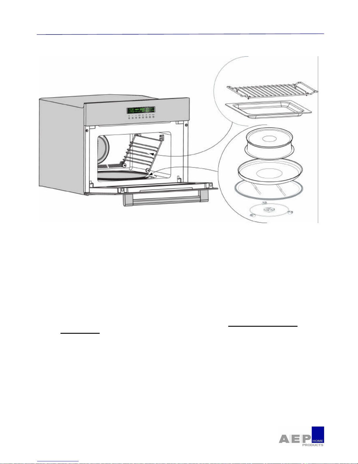
• .Build-in oven : possibility to be built -into a 450 mm niche.
• Cavity : 35 L enamelled black or stainless natural cleaning.
• Turn tabl e integrated 36 cm : It is placed in the recess of the cavity, it turns, thanks to a driver,
indifferently in both directions and allows a homogeneous cooking of food.
• Door : Hinges with a compensated opening.
• The side racks : Three levels.
• The Grid : Allows you to toast, brown or roast.
• Special microwave plate cover : Food retains full flavour due to the steam effect. Dishes are
heated evenly throughout. Drying out of food is minimised. Programme time can be reduced.
By preventing splattering, it helps you to keep your oven clean Use with the microwave
function only.
• The Pizza dish : Use the Pizza dish with the automatic cook or grill and microwave function to
save energy. Your favourite dishes will turn out a crispy, tasty and golden brown as if cooked in a
traditional oven.
• The glass drip tray : It may be used as a cooking dish.
• Two exits of waves : Two waves outlets for a better distribution of cooking. High cooking and low
cooking, with a splintering from in the wave guide located at the level of each outlet. Those are
equipped with a guard guides mica waves.
• Distributor of waves : embossing located on the left wall designed to splinter the flow of waves.
• The control panel : With height buttons for ATAG
With four buttons and two knobs for PELGRIM
Page 5
MC4111L / MAG 690
Technische Documentatie
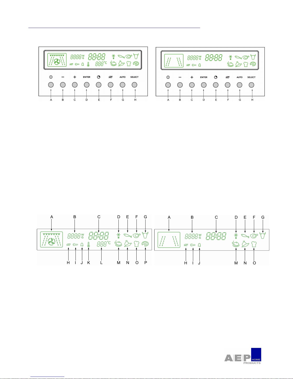
1.1. - Control panel for ATAG Combi and Solo models
A) The START/STOP button lets you begin a program, interupt or cancel a program in progress.
B and C) The - / + buttons allow you to adjust the program length, the weight , the temperature, the
time, the food category, and power levels.
D) Use the ENTER button to confirm a selection or to use the memory function.
E) The clock button allows you to set the time.
F) The TURNTABLE STOP button stops the turntable from revolving in order to use platters which
require the entire oven space.
G) The AUTO button allows you to select the automatic function and food type of your choice.
H) The SELECT button is used to set the desired cook function.
1.1.1. - The display Combi and Solo
A - Programmed function
B - Microwave level / Food weight
C - Programme time / Cloktime
D - Automatic defrost
E - Fish
F - Poultry
G - Meat
H - Stop turntable
I -
Child lock
J - Timer
K - Temperature display
L - Fan cook temperature / Grill level
M - ready-made dishes
N - Vegetables
O - Bread
P - Pizza
Page 6
MC4111L /MAG 690
Technische documentatie
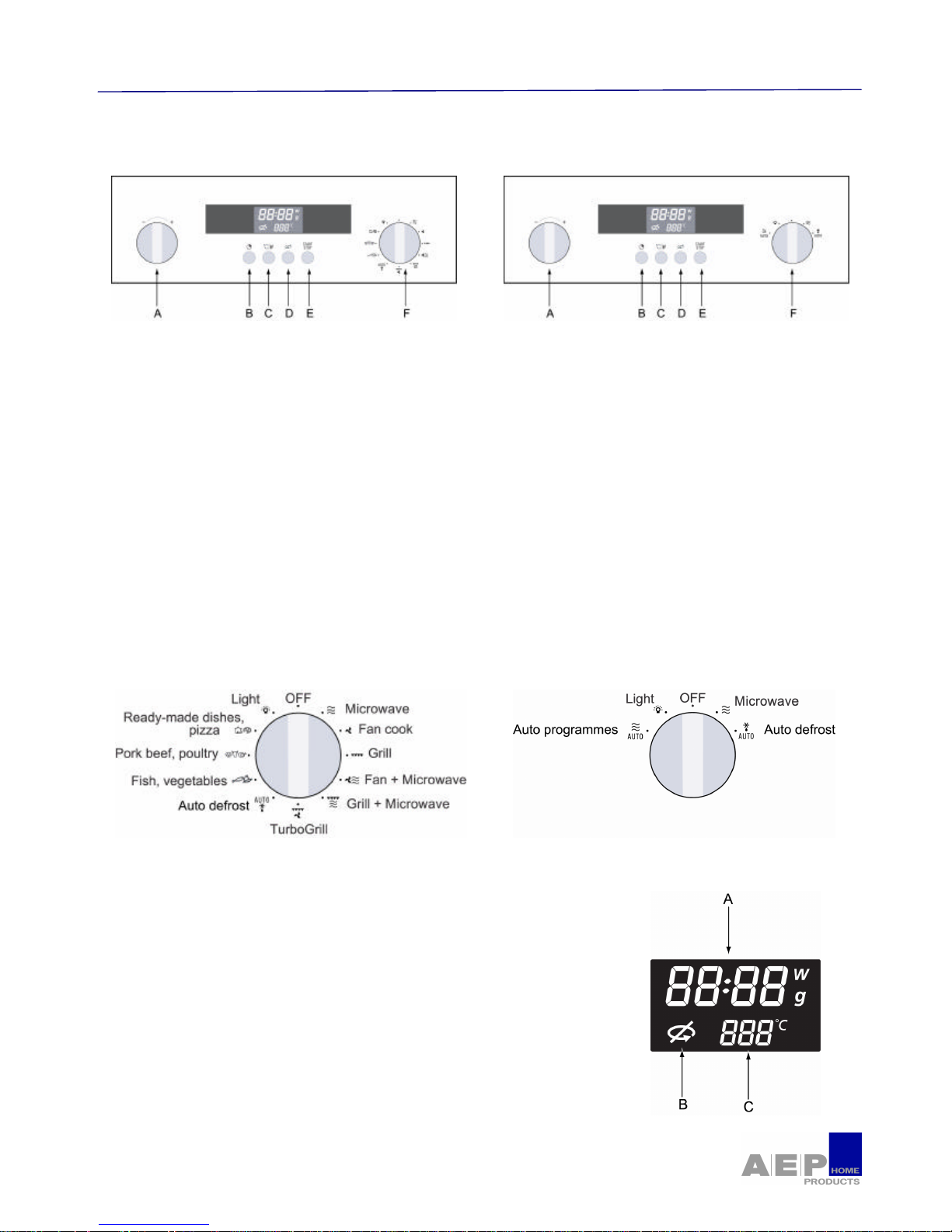
1.2. - Control panel for PELGRIM Combi and Solo models
A) The - / + selector knob allows you to adjust the time, the programme length, the power levels, the
food category, the food portion’s weight, as well as the temperature for a fan cooking programme.
B) The CLOCK button allows you to set the time.
C) The °C / W button you to validate your selections.
D) The TURNTABLE STOP button Stops the turntable from revolving in order to use platters which
require the entire oven space.
E) The START / STOP button lets your begin a programme, interrupt or ca ncel a programme in
progress.
F) The FUNCTION / AUTO PROGRAMME selector knob allows you to choose the type of
programme, as well as the automatic function and food category.
1.2.1. - The FUNCTION selector knob Combi and Solo
1.2.2. - The display
A) Cloktime, programme time, microwave power level (W watts)
food Weight (g grams).
B) Stop turntable.
C) Fan cook temperature , grill level, auto programmes.
Page 7
MC4111L / MAG 690
Technische Documentatie
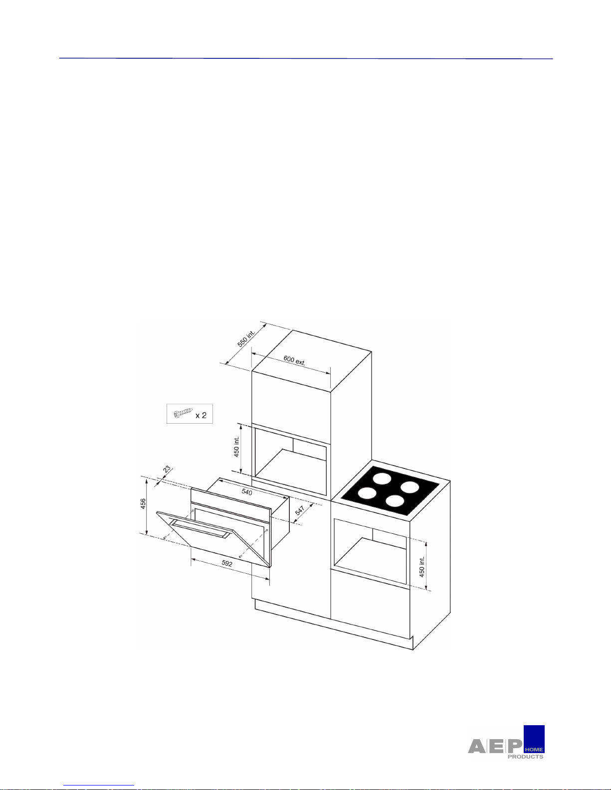
1.3. - Installation
1.3.1. - Build-in
The appliance may be installed beneath a work surface or in column housing (open or closed) which has
the required built-in measurements.
The oven has an optimised air flow which makes it possible to obtain a correct operation of the appliance
and remarkable results of cooking by respecting the following instructions:
• the oven can be installed in a piece of furniture of kitchen in column but also under an open or
closed counter.
• the material of the column housing must be heat resistant.
• The oven should be placed in the niche once its electrical supply has been cut off.
• For more stability, fix the oven in the column housing using 2 screws.
Page 8
MC4111L / MAG 690
Technische documentatie
1.4. - Electric connection
Before connecting of the appliance, check that it has not been damaged during the transport (Door or
deformed seal).
Check that :
The electrical installation has sufficient voltage.
The supply cables are in good condition.
The diameter of the wires complies with the installation requirements.
The installation must be protected with a fuse 16 A.
The responsibility for the manufacturer could not be committed in the event of consecutive accident
with an ground electrical non-existent or incorrect.
Electrical safety must be ensured through proper installation in the housing. During installation and
maintenance operations, the appliance must be unplugged from the electrical grid ; fuses be cut off or
removed.
This plug must be easily accessible after installation.
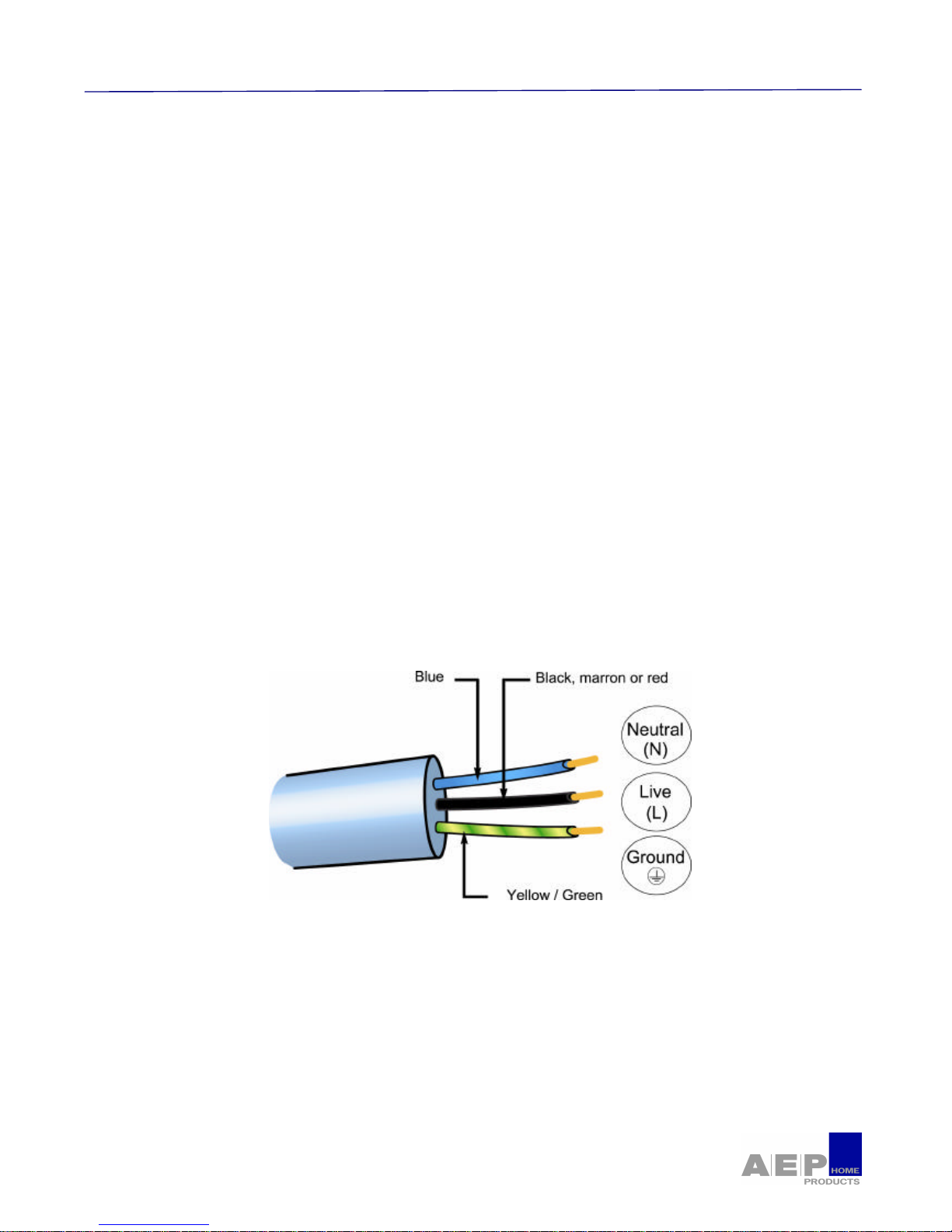
The appliance must be connected using a (standardised) feeder cable with 3 conductors of 1,5 mm2
(1 Live + 1 neutral + ground) which must be connected to the 220-240 V ~ monophase network using a
CEI 60083 standardised 1 Live + 1 neutral + ground electrical outlet or one which complies with
installation requirements. The protection cable (green-yellow) is connected to the appliance’s ground
terminal and must be connected to the appliance’s ground.
Page 9
MC4111L / MAG 690
Technische Documentatie
2 - USE
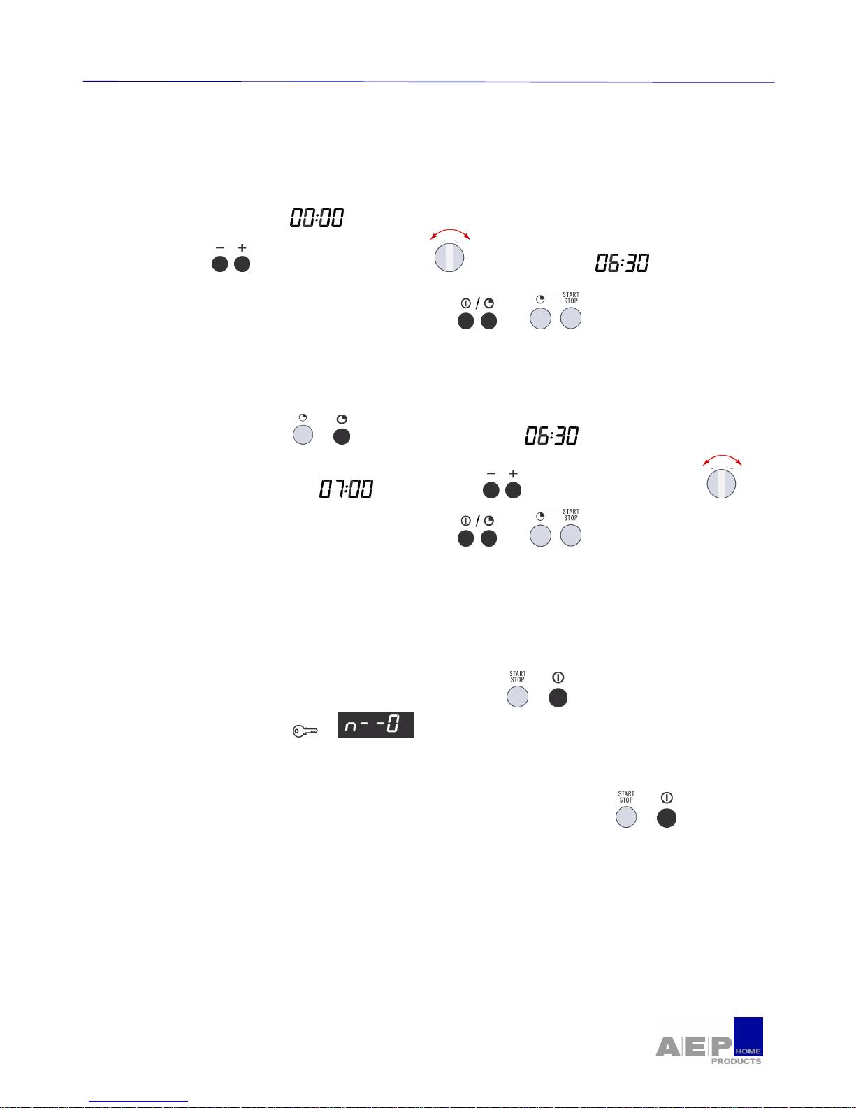
2.1. - How to set / Change the time
After connecting your appliance or after a prolonged power failure.
Ø To set the clock
• Flashes in the display.
• Press the buttons or turn the selector to set the time, ex.
• Confirm by pressing the Clock or Start buttons , or . A beep confirms that your
clock is set.
Ø When there is a time change
• Press the Clock button or . The time display flashes.
• Program the new time ex : by pressing the keys or turning the selector .
• Confirm by pressing the Clock or Start buttons , or . A beep confirms that your
clock is set to the new time.
2.2. - Child lock
Ø You can program the "Child Lock " feature to block unauthorized use of your microwave
oven.
• To set : open the door and Press the START/STOP key or , for 5 seconds, until the key
appears in the display. or . 2 beeps confirm that your microwave is temporarily
locked.
No program is available.
• To cancel : Follow the same procedure. Press the START/STOP Button or , for 5
seconds with the door open. The key symbol switches off and clocktime is displayed.
The procedure is confirmed by 2 beeps.
Page 10
MC4111L / MAG 690
Technische Documentatie
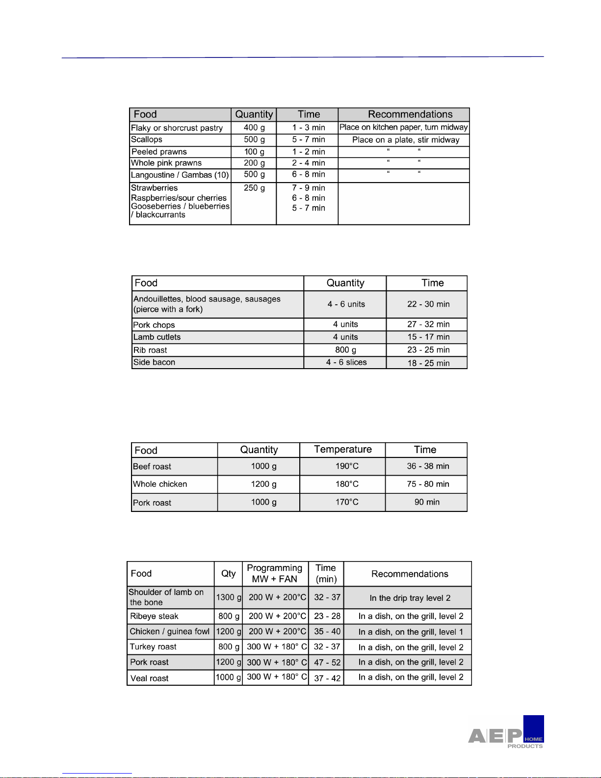
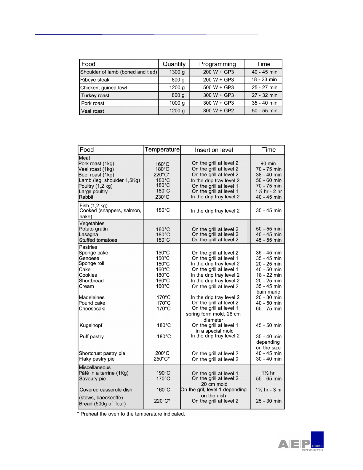
2.3. - Cooking Guides
2.3.1. - Automatic defrosting guide
2.3.2. - High grill guide
Place the food item on the grill and insert at level 3. Turn the food halfway through cooking.
2.3.3. - Turbo grill guide
Place the food item in a dish on the grill at insertion level 1
Turn the food halfway through cooking.
2.3.4. - Fan + microwave guide
Page 11
MC4111L / MAG 690
Technische Documentatie
2.3.5. - Grill + microwave guide
2.3.6. - Fan cooking guide
Page 12

MICROWAVE OVEN MOBI
Formation technique
PRINCIPE
- 12 -
CU3P-MOBI-002-09/05
3 - USING A MICROWAVE OV EN
To prevent the deterioration of the appliance, never operate it empty.
3.1. - Dishes
Do not use metallic or circled with metal dishes, tin foil, plates with golden or silver line, crystal
glasses (containing lead). The food in metal boxes must be poured into a microwave friendly dish
because they can cause damage.
Metal accessories (Rack) given with microwave ovens are insulated from the cavity by plastic or
porcelain fixing. Their form and dimension are calculated not to disrupt the normal propagation of
waves and prevent flashes.
Use round or oval dishes made of porcelain, earthenware, Pyrex or certain kinds of plastic made for
microwave ovens. The dishes made of normal plastic may only be used for water cooking bec ause fat
can deteriorate them.
The crisp dish is an utensil reacting to microwaves. It heats up the food, which prevents a soggy pastry
as for pizza. It also allows to sear and cook small pieces of meat or to reheat a ready -made dish.
Cover the food with a plate, the lid of the dish, greaseproof paper or plastic film pierced before cooking
to prevent spattering.
PLEASE NOTE : It’s better not to use
stoneware dishes because stoneware contains
water and absorbs waves and heat-up.
To check that a dish can be used in a
microwave oven, put it in the appliance with a
glass full of iced water near it. After two minutes,
it must be barely warm.
Page 13
MC4011L / MAG 690
Technische Documentatie
4 - PRINCIPLE OF THE MOBI MICROWAVE OVEN
4.1. - Constitution
The MOBI microwave oven comprises a microwave transmitter called magnetron. The emitted waves are
confined in a recess called cavity. This cavity is closed by a door coupled to a safety device to avoid the
emission of waves outside the oven. A wave distributor and a turntable contribute to a better distribution of
the waves on food. It contains an electric feeding system and command elements. The microwaves are
absorbed by food. But while penetrating, they gradually lose their power. Beyond two to three centimeters,
cooking is done by conduction. The microwave oven and the food do not accumulate electromagnetic
energy. When the magnetron is no longer electrically powered, the emission of stops.
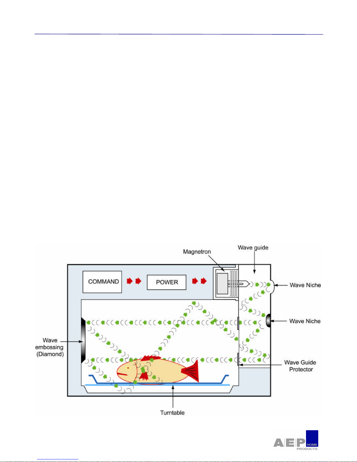
4.2. - Diffusion and distribution of the waves in the cavity
The waves are spread in the wave guide. As soon as they leave the magnetron, they are splintered by an
oval niche. The waves will go down the guide, then they again will be further splintered by the second
niche. The flow of waves will penetrate the cavity through two entries, high and low, to ensure a better
distribution for cooking.
The two entries are protected by "MICA" plates in order to prevent the guide from being spattered during
cooking.
A diamond embossing, placed in the cavity and located opposite the two wave guide outlets, splinters the
waves once again for maximum waves distribution.
The turntable, revolving food in the flow of waves, improves the distribution even more, thus obtaining a
homogeneous cooking.
Page 14

MC4111L / MAG 690
Technische Documentatie
4.3. - The cooling system
The double blower takes the air by an entry located between the panel and the oven door.
This air will cool all the components located in the upper part of the oven, and particularly the electronic
card, but also all the other elements. An exit located under the door is used to expel this air.
The blower, equipped with two turbines, powers two air ventilation systems.
Right turbine
The air forced by the right turbine flows through in
an air duct and cools the magnetron. The air flow
enters in the cavity in order to ventilate it.
The air rises between the top of the cavity and an
intermediate sheet .It is expelled in the oven low
parts, located below the door.
Left turbine
The air forced by the left turbine is aspired and cools the
components of the wave chain, (Transformer, high voltage
diode and capacitor), and the fan heat unit. The air is then
expelled out the oven sides and the bottom to leave below
the door.
Page 15

MC4111L / MAG 690
Technical Training
4.4. - Principle of the shutter operation
The "Damper" shutter consists of two parts used for blocking the air inlets and outlets of the cavity.
Depending on the desired cooking mode (Microwave, combined, traditional), the printed circuit board
controls a "Wax actuator" thermal activator. Through its piston, this actuator acts on the shutter and sets it
to open or closed position.
By default, th e shutter is in the closed position, that is to mean that the shutters rest on the cavity top.
4.4.1. - Shutter position in microwave mode
In microwave mode, the shutter is closed
(down position), the air arriving from the
right-hand turbine ventilates the
magnetron and enters the cavity through
the holes located near the door. The air
flow goes out through the holes located 5
cm behind the door, at the grill heating
element.
The wax activator is not energized
(not actuated).
Page 16

MC4111L / MAG 690
Technische Documentatie
4.4.2. - Shutter position in Combined or Traditional mode
In Combined or Traditional mode, the shutter is
open (up position), the air arriving from the righthand turbine ventilates the magnetron and then
is deflected towards an opening located near the
magnetron. The air flow circulates then between
the intermediate sheet metal and the cavity top,
goes out on the sides of the oven and is
expelled underneath the door.
The thermal activator ( or actuator) is
energized (Actuated).
In Combined or Traditional cooking mode, the shutter is open, the first part of which prevents the cavity hot
air from being sucked by the air flow circulating around the cavity. The second part of the shutter prevents
the fresh air from entering the cavity, while ensuring the magnetron ventilation, necessary in combined
mode.
4.4.3. - The door ventilation
The MOBI oven door is ventilated in order to obtain
the lowest temperature on the door (55°C where as
the limit value imposed by the standard is 70°C).
The principle consists of making air circulate inside
the door to reduce thermal exchange. The door is
equipped with two openings, one at the top and
the other at the bottom. While functioning, the
turbine creates a depression which makes the cold
air penetrate through an entry located at the bottom
of the door. The aspired cold air goes up along the
panes inside the door thus cooling the whole unit.
The hot air goes out through the lower part of the
oven; a deflector at the bottom of the door directs
the flow downwards to prevent the hot air from
being expelled toward the user .
The three panes of the door reduce the infra-red
radiation.
Page 17

MC4111L / MAG 690
Technical Training
4.5. - Door lock
The door imperatively must be closed during the magnetron operation. It is fitted with a mechanical locking
system, which controls the switches and the electrical power supply to the appliance. The switches only
operate if the door is properly closed.
This safety device consists of switches built in the low -voltage circuit, so as to allow power supply to the
transformer (and, therefore, to the magnetron), depending on the door position. A double safety device also
exists, which consists of a switch mounted in the contrary manner. It is open when the door is closed and is
closed when the door is open. When the door is closed, the switches are closed and enable the magnetron
to start. As soon as the door is opened, they open and cut instantaneously the power supply to the
transformer, and thus the emission of waves. In the event where the first safety switch would remain
closed, the back up switch would short out the low-voltage circuit and would trigger the general fuse of the
appliance, so ensuring the user's safety.
Two door locks are built in the up rights of the oven, positioned on the right and on the left underneath the
panel.
The right-hand lock integrates the secondary microswitch
and a cam.
When the door is closed, the hook actuates the cam which,
by revolving on itself, actuates the microswitch.
The left-hand lock integrates the primary microswitch, the
control microswitch which drives a cam.
When the door is closed, the hook actuates the cam, which, by
revolving on itself, actuates both microswitches.
Checked element
Test points
Ohmic value
Opened door
Ohmic value
Closed door
Primary Switch SW1 no-com Infinite
0Ω
Control Switch com -nc
0Ω
Infinite
Control Switch com -no Infinite
0Ω
Secondary
Switch SW2
no-com Infinite 0Ω
Closed door
Closed door
Page 18

MC4111L / MAG 690
Technische Documentatie
4.6. - The various cooking modes
4.6.1. - The microwave mode
The magnetron is monitored. The set point power is comprised between 100W and 1000W.
The power set point (1000W maximum) and the operating duration (59 min - 59 s maximum) are
transmitted by the display board.
The magnetron control is computed on a basis of 30 seconds.
4.6.2. - The grill mode
The element grill is ordered according to desired cooking (strong grill, soft grill), according to the preset
times and cyclic preset.
? Strong grill: continuous operation during 11 minutes 30 seconds then 90/130 seconds cyclic
preset.
? Soft grill: continuous operation during 3 minutes 30 seconds then 70/110 seconds cyclic
preset.
4.6.3. - The fan cooking mode
The fan heating element is controlled according to the temperature transmitted by the probe (NTC),
placed in the cavity, with respect to the selected set point.
POWER in Watts Cyclic report in Second
100 5/30
200 8/30
300 11/30
400 14/30
500 17/30
600 20/30
700 23/30
800 25/30
900 28/30
1000 30/30
Page 19

MC4111L / MAG 690
Technical Training
5 - POWER SUPPLY TO POWER CIRCUIT
The transformer primary winding is energized
by parallel-mounted relay and triac.
The triac is made conductive when the voltage
is maximum, in order to have minimum current
(owing to the phase shift related to the
transformer winding choke coil).
So, it enables the magnetron to be energized
at a predetermined moment, unlike the relay,
which has a none precise switching time
(6 to 20 ms).
On the board, a "mains synchro." synchronises the microprocessor clock with the rising curve of the
voltage.
When pressing "START", the triac is controlled on the maximum voltage.
As the triac cannot withstand the power for a very long time, the relay will supply the primary winding of the
transformer for the rest of the time .
Page 20

MC4111L / MAG 690
Technische documentatie
6 - THE DIFFERENT COMPON ENTS
Designation Function Characteristics
Metallic grid
In grill function, it makes it possible to
brown food.
In Fan cooking: To pose the dishes on the
grid in low position to obtain a better
distribution of heat and optimal of cooking
results.
The glass drip tray
It can be used half filled of water for
cooking with the “bain-marie” in fan
cooking function or as cooking dish.
The side racks
The side racks make it possible to insert
the accessories on 3 levels.
The 3 levels of insertions are available
according to the type of food cooking.
• Two ceramic supports located of
each side of the cavity are used to hang
the racks.
• Two Teflon pieces located in bottom
of the racks avoid contacts with cavity.
The turntable
It makes it possible to homogenise
cooking.
• Diameter : 360 mm
• 4,2 t/min (1 motor speed)
The drive system
Allows the turntable to turn in the two
directions :
- A driver
- A base roller
The unit allows an easy starting of the
plate.
The wheels of the roller are in Teflon.
They are assembled free on their axe.
The turntable only is in contact with the
wheel, to reduce frictions.The free
assembled plastic base plate is aligned
by gravity.
• Possibility to clean in the dishwasher
safe.
Page 21

MC4111L / MAG 690
Technische documentatie
Designation Function Characteristics
Turntable motor
Synchronous motor without preferential
rotating direction.
It is protected from overflow by a plastic
protector.
• 230/240 V ∼
• 4,2 t/min
• 15,6 KΩ
• 2 W
It can be dismantled when opening the
metal sheet of the bottom with a cutting
plier. To mount again the metal sheet, two
screws are given with the new motor.
Door Lock
Composed of integrated switches
actuated by the door hooks.
Door
It comprises :
• a glass pane to be able to supervise
food in the course of cooking. Sealing
carried out by a perforated sheet (metal
grid).
• A waves trap
• A framework equipped with a damper
in heat resistant PPS
• Two door hooks integrated in the
thickness of the door
• Two hinges equipped with a folding
strip in order to be able to disassemble
the oven door.
(simplification of cleaning and
disassembling)
• A handle
Power Card
Protects the wave guide from spattering
from cooking.
Commands elements (Triac and relay)
It controls the elements of power under
the control of the display card, the
selector, the probe and the
microswitches.
Hour maintenance with capa.30 hours.
Time keeping with 30 H capacity
Wave protector
Allows protecting the guide from waves of
the splashes of cooking.
It is a plate which covers the outlets of
waves.
Cavity equipped with a reinforcement
located at its top, to protect the access to
the grill.
• Mica
Page 22

MC4111L / MAG 690
Technische documentatie
Designation Function Characteristics
Circular heating element and its
thermostat
This ventilated heating element is only
used for the ‘COMBI’ models
Resistor
• 230 V ∼
• 1600 W
• 32,5 Ω
Thermostat
• 130°C
Ventilator Motor
This element allows to forced the air
through the heating resistor to the cavity.
• 220/240 V ∼
• 100 Ω
• 30 W
• Asynchronous motor
Grill
Grill element
• Horizontal position: Classical grill to
use with the microwave function.
• 220/240 V ∼
• 30 Ω
• 1750 W
Probe
The probe transmits the oven
temperature to the microprocessor.
NTC
- 215kΩ at room temperature (20°C)
- 1kΩ at 200°C
Fan motor
It is composed of motor and two turbines.
It ventilates
- Magnetron
- Cavity inside
- Cavity outside
- Electronic card
- Convection unit
- Micro waves line components
• 220/240 V ∼
• 60 Ω
• 43 W
Page 23

MC4111L / MAG 690
Technische documentatie
Designation Function Characteristics
Thermal Activator When Thermal activator is on, the shutter
is open.
• 220/240V~
• 5 W
• 830 Ω
• Head in Teflon
Panel
assembly principle is the same as EURO
oven
Panel decor fixed with clips
Panel support fixed with two screws
component fixed with two screws
Be careful: A spring is fixed between
support and panel, it allows feedback
effect. It prevents the electromagnetic
perturbations feedback in
the oven
panel.
Magnetron and its thermostat
The magnetron is fix ed to the cavity by a
¼ of round system. It gives an easy
assembly and dismantling.
Magnetron includes a thermostat which
protects from overheating.
Magnetron
• 1000W
• 2450 Mhz
Thermal security
• Cut : 110°C for Combi
• Cut : 90°C for Solo
Voltage doubler
The voltage doubler transforms the
2100V~ alternative voltage into a
negative pulsated current of about
4000V~.
It is made up of two components :
• A capacitor which stores electrical
energy for half a period.
• A high voltage diode which,
together with the capacitor, enables the
alternative high voltage to be converted
into negative voltage.
No AK protector
Diode
• Voltage lowering : 10 V max
Capacitor
• 1,05 µF
• 2100 V ∼
Transformer
One primary coil, two secondary coils :
• 3,3V~ at LV to ensure the cathode
filament heating.
• 2100V~ at HV is applied to the
voltage doubler and the magnetron
anode. One end of the coil and the
magnetron are connected to the oven
earth.
The primary coil includes an
overheating security thermostat.
Primary coil
• 230/240 V ∼
• 1,5 Ω
Secondary HV
• 2100 V ∼
• 75 Ω
Secondary LV
• 3,3 V ∼
• 0,5 Ω
Page 24

MC4111L / MAG 690
Technische documentatie
7 - ELECTRICAL DIAGRAM PELGRIM SOLO
Page 25

MC4111L / MAG 690
Technische documentatie
8 - ELECTRONIC CARD PELGRIM SOLO
Controls must be done over voltage with connectors disconnected
ON THE OHMMETER
Mark
Component
Ohm
Ph – Fan motor
Fan motor
60 Ω
Ph - Lamp
Lamp
192 Ω
Ph – Turntable motor
Turntable motor
15,7 kΩ
Page 26

MC4111L / MAG 690
Technische documentatie
9 - TEST PROGRAM PELGRIM SOLO
9.1. - Important instructions
• To place a container filled with water in the oven (for the tests in microwave modes).
• To connect (if possible) an ammeter on the power supply of the oven.
• Entirely execute the test program.
• Record discrepancies noticed as the test program is running.
• Next, check and replace if necessary the incriminated component(s).
• Perform right-operation check by executing the test program.
9.2. - Conditions of entry
• Set the time to 12 : 00
• Press successively 1-2-3-4-3-2 and hold 1, 5 seconds minimum.
9.3. - Run of the test program
Step Run and display Remarks
1
Software checking
• Displaying the software number : 1006
NO ⇒ If connections to power card are OK, then display
card out of order.
Continue the test
2
Software checking
• Displaying the evolution n° of the software.
NO ⇒ If connections to power card are OK, then display
card out of order.
Continue the test
3
Button checking
• Button checking
NO ⇒ If connections to power card are OK, then Button
or display out of order.
Continue the test
4
Right rotary switch checking
• Right rotary switch checking
NO ⇒ If connections to power card are OK, then Right
rotary switch or display out of order.
Continue the test
5
Right rotary switch checking
• Right rotary switch checking
NO ⇒ If connections to power card are OK, then Right
rotary switch or display out of order.
Continue the test
6
Right rotary switch checking
• Right rotary switch checking
NO ⇒ If connections to power card are OK, then Right
rotary switch or display out of order.
Continue the test
Page 27

MC4111L / MAG 690
Technische documentatie
Step Run and display Remarks Step
7
Right rotary switch checking
• Right rotary switch checking
NO ⇒ If connections to power card are OK, then Right
rotary switch or display out of order.
Continue the test
8
Buttons checking
• Button checking
NO ⇒ If connections to power card are OK, then button or
display out of order.
Continue the test
9
Buttons checking
• Button "START/STOP" checking
NO ⇒ If connections to power card are OK, then button or
display out of order.
Continue the test
10
Buttons checking
• Button "TURNTABLE" checking
NO ⇒ If connections to power card are OK, then button or
display out of order.
Continue the test
11
Buttons checking
• Button "°C/W" checking
NO ⇒ If connections to power card are OK, then button or
display out of order.
Continue the test
12
Buttons checking
• Button "CLOCK" checking
NO ⇒ If connections to power card are OK, then button or
display out of order.
Continue the test
13
Action
• Button checking
NO ⇒ If connections to power card are OK, then button or
display out of order.
Continue the test
14
Left rotary switch checking
• Left rotary switch checking
NO ⇒ If connections to power card are OK, then Left
rotary switch or display out of order.
Continue the test
15
Left rotary switch checking
• Left rotary switch checking
NO ⇒ If connections to power card are OK, then Left
rotary switch or display out of order.
Continue the test
Page 28

MC4111L / MAG 690
Technische documentatie
Step Run and display Remarks Step
16
Checking the Microwaves function
• The magnetron, The cooling fan, the lamp, the
turntable motor are on.
I absorbed = 4,6A
NO ⇒ If components, fuse, door switch, thermostat,
transformer, diode, capacitor and wiring OK then Power
card out of order.
When door is opened, only lamp stays on.
Continue the test
17
Turntable checking
• The Turntable is ON (Stays on even when opening
the door)
Continue the test
18
Checking cooling fan
5s mini after the beginning of step 8
Only cooling fan is on. it stays on when door is opened
Continue the test
19
Checking the display
5s mini after the displaying of the “:”
form step 9
All the LCD is on.
During this step, the closing of the damper could be
checked.
The cooling fan is ON even when door is open.
Continue the test
20
Checking the clock
Random time is displayed. Check that time is incrementing.
If the RTC (Real Time Cl ock) is not OK: “Err2” is
displayed.
Continue the test
21
Checking the MW function
• The magnetrons, the cooling fan, the lamp, the
turntable motor are on.
I absorbed = 4,6A
NO ⇒ If components, fuse, door switch, thermostat,
transformer, diode, capacitor and wiring OK then Power
card out of order.
When door is opened, only lamp stays on.
Continue the test
22
5s mini after the beginning of step
10
Exit of the DAP
Once the defective element(s) are replaced,
repeat the program of aid to diagnostic to validate the repair
Page 29

MC4111L / MAG 690
Technische documentatie
10 - ELECTRICAL DIAGRAM ATAG SOLO
Page 30

MC4111L / MAG 690
Technische documentatie
11 - ELECTRONIC CARD ATAG SOLO
controls must be done over voltage with connectors disconnected
ON THE OHMMETER
Mark
Component
Ohm
Ph – Fan motor
Fan motor
60 Ω
Ph - Lamp
Lamp
192 Ω
Ph – Turntable motor
Turntable motor
15,7 kΩ
Page 31

MC4111L / MAG 690
Technische documentatie
12 - TEST PROGRAM ATAG SOLO
12.1. - Important instructions
• To place a container filled with water in the oven (for the tests in microwave modes).
• To connect (if possible) an ammeter on the power supply of the oven.
• Entirely execute the test program.
• Record discrepancies noticed as the test program is running.
• Next, check and replace if necessary the incriminated component(s).
• Perform right-operation check by executing the test program.
12.2. - Conditions of entry
• Set the time to 12 : 00
• Press successively 1-2-3-4-3-2 and hold 1,
5 seconds minimum.
12.3. - Run of the test program
Step Run and display Remarks
1
Software checking
• Displaying the software number : 1004
NO ⇒ If connections to power card are OK, then display
card out of order.
Continue the test
2
Software checking
• Displaying the evolution n° of the software.
NO ⇒ If connections to power card are OK, then display
card out of order.
Continue the test
3
Buttons checking
• Right switch board checking
NO ⇒ If connections to power card are OK, then Right
switch board out of order.
Continue the test
4
Buttons checking
• Right switch board checking (SELECT)
NO ⇒ If connections to power card are OK, then Right
switch board out of order.
Continue the test
5
Buttons checking
• Right switch board checking (AUTO)
NO ⇒ If connections to power card are OK, then Right
switch board out of order.
Continue the test
6
Buttons checking
• Right switch board checking (TURNTABLE)
NO ⇒ If connections to power card are OK, then Right
switch board out of order.
Continue the test
7
Buttons checking
• Right switch board checking (CLOCK)
NO ⇒ If connections to power card are OK, then Right
switch board out of order.
Continue the test
8
Buttons checking
• Left switch board checking
NO ⇒ If connections to power card are OK, then display
card out of order.
Continue the test
9
Buttons checking
• Right switch board checking (-)
NO ⇒ If connections to power card are OK, then display
card out of order.
Continue the test
Page 32

MC4111L / MAG 690
Technische documentatie
Step Run and display Remarks
10
Butto ns checking
• Right switch board checking (+)
NO ⇒ If connections to power card are OK, then Right
switch board out of order.
Continue the test
11
Buttons checking
• Right switch board checking (ENTER)
NO ⇒ If connections to power card are OK, then Right
switch board out of order.
Continue the test
12
Checking the Microwaves function
• The magnetron, The cooling fan, the lamp, the
turntable motor are on.
I absorbed = 4,6A
NO ⇒ If components, fuse, door switch, thermostat,
transformer, diode, capacitor and wiring OK then Power
card out of order.
When door is opened, only lamp stays on.
Continue the test
13
Turntable checking
• The Turntable is ON (Stays on even when opening
the door)
Continue the test
14
Checking the cooling fan
• When the co oling fan could be checked, the colon of
the time is bilking.
• Only cooling fan is on. it stays on when door is
opened
Continue the test
15
Checking the display
All the LCD are on.
During this step, the closing of the damper could be
checked.
The cooling fan is ON even when door is open.
Continue the test
16
Checking the Clock
Random time is displayed. Check that time is
incrementing.
If the RTC (Real Time Clock) is not OK : “Err2” is
displayed.
Continue the test
17
Checking the Microwaves funct ion
• The magnetron, The cooling fan, the lamp, the
turntable motor are on.
I absorbed = 4,6A
NO ⇒ If components, fuse, door switch, thermostat,
transformer, diode, capacitor and wiring OK then Power
card out of order.
When door is opened, only lamp st ays on.
Continue the test
18
5 s mini after the beginning of the
set 16
Exit of the test
Once the defective element(s) are replaced,
repeat the program of aid to diagnostic to validate the repair
Page 33

MC4111L / MAG 690
Technische documentatie
13 - ELECTRICAL DIAGRAM PELGRIM COMBI
Page 34

MC4111L / MAG 690
Technische documentatie
14 - ELECTRONIC CARD PELGRIM COMBI
controls must be done over voltage with connectors disconnected
ON THE OHMMETER
Mark
Component
Ohm
Ph - Gril
Gril
30 Ω
Ph – Convection grill
Convection grill
32,5 Ω
Ph - Fan motor
Fan motor
60 Ω
Ph - Lamp
Lamp
192 Ω
Ph - Turntable motor
Turntable motor
15,7 kΩ
Ph – Thermal activator
Thermal activator
820 Ω
Ph - Convection grill motor
Convection grill
motor
100 Ω
Probe
Probe
215 kΩ à 20°C
Page 35

MC4111L / MAG 690
Technische documentatie
15 - TEST PROGRAM PELGRIM COMBI
15.1. - Important instructions
• To place a container filled with water in the oven (for the tests in microwave modes).
• To connect (if possible) an ammeter on the power supply of the oven.
• Entirely execute the test program.
• Record discrepancies noticed as the test program is running.
• Next, check and replace if necessary the incriminated component(s).
• Perform right-operation check by executing the test program.
15.2. - Conditions of entry
• Set the time to 12 : 00
• Press successively 1-2-3-4-3-2 and hold 1, 5 seconds minimum.
15.3. - Run of the test program
Step Run and display Remarks
1
Software checking
• Displaying the software number : 1007
NO ⇒ If connections to power card are OK, then display
card out of order.
Continue the test
2
Software checking
• Displaying the evolution n° of the software.
NO ⇒ If connections to power card are OK, then display
card out of order.
Continue the test
3
Buttons checking
• Right switch board checking
NO ⇒ If connections to power card are OK, then Right
switch board out of order.
Continue the test
4
Right rotary switch checking
• Right switch board checking (POSITION 1 TO 11)
NO ⇒ If connections to power card are OK, then Right
switch board out of order.
Continue the test
5
Right rotary switch checking
• Right switch board checking (LAST POSITION)
NO ⇒ If connections to power card are OK, then Right
switch board out of order.
Continue the test
6
Buttons checking
• Button checking
NO ⇒ If connections to power card are OK, then button
or display out of order.
Continue the test
Page 36

MC4111L / MAG 690
Technische documentatie
Step Run and display Remarks
7
Buttons checking
• Button "START/STOP" checking
NO ⇒ If connections to power card are OK, then button or
display out of order.
Continue the test
8
Buttons checking
• Button "TURNTABLE" checking
NO ⇒ If connections to power card are OK, then button or
display out of order.
Continue the test
9
Buttons checking
• Button "°C/W" checking
NO ⇒ If connections to power card are OK, then button or
display out of order.
Continue the test
10
Buttons checking
• Button "CLOCK" checking
NO ⇒ If connections to power card are OK, then button or
display out of order.
Continue the test
11
Action
• Button checking
NO ⇒ If connections to power card are OK, then button or
display out of order.
Continue the test
12
Left rotary switch checking
• Left rotary switch checking
NO ⇒ If connections to power card are OK, then Left
rotary switch or display out of order.
Continue the test
13
Left rotary switch checking
• Left rotary switch checking
NO ⇒ If connections to power card are OK, then Left
rotary s witch or display out of order.
Continue the test
14
Functions checking
• The magnetron, the girl, The cooling fan, the lamp,
the turntable motor, the damper are on.
• Check the MW leakage
I absorbed = 14,7A
NO ⇒ If components, fuse, door switch, thermostat,
transformer, diode, capacitor and wiring OK then Power
card out of order.
to let cooking 2 has 3 minutes for the continuation of
the test
Continue the test
15
Turntable checking
• The Turntable is ON (Stays on even when opening
the door)
Continue the test
Page 37

MC4111L / MAG 690
Technische documentatie
Step Run and display Remarks
16
Checking the damper
5s mini after the beginning of step 6
• When the damper could be checked, the colon of the
time is bilking.
Only damper and cooling fan are on. Those stay on when
door is opened
Continue the test
17
Checking the display
5s mini after the displaying of the “:”
form step 7
§ All the LCD are on.
During this step, the closing of the damper could be
checked.
The cooling fan is ON even when door is open.
Continue the test
18
Checking the clock
§ Random time is displayed. Check that time is
incrementing.
If the RTC (Real Time Clock) is not OK : “Err2” is
displayed.
Continue the test
19
Checking the MW function
• The magnetron, the cooling fan, the lamp, the
turntable motor are on.
I absorbed = 4,6 A
NO ⇒ If components, fuse, door switch, thermostat,
transformer, diode, capacitor and wiring OK then Power
card out of order.
When door is opened, only lamp stays on.
Continue the test
20
Checking the MW + hot air function
5s mini after the beginning of step 10
The oven must be hot, if not defect codes “ERR0”
On the display the conversion value of the temperature
captor (i.e. : 236 ). If the T° captor is OK the value is
decreasing.
The magnetron, the hot air heater, the cooling fan, the hot
air fan, the lamp, the turntable motor and the damper are
on.
When door is opened, only lamp and damper are on.
Continue the test
21
5s mini after the beginning of step 11
Exit of the D AP
Once the defective element(s) are replaced,
repeat the program of aid to diagnostic to validate the repair
Page 38

MC4111L / MAG 690
Technische documentatie
16 - ELECTRICAL DIAGRAM ATAG COMBI
Page 39

MC4111L / MAG 690
Technische documentatie
17 - ELECTRONIC CARD ATAG COMBI
controls must be done over voltage with connectors disconnected
ON THE OHMMETER
Mark
Component
Ohm
Ph - Gril
Gril
30 Ω
Ph – Convection grill
Convection grill
32,5 Ω
Ph - Fan motor
Fan motor
60 Ω
Ph - Lamp
Lamp
192 Ω
Ph - Turntable motor
Turntable motor
15,7 kΩ
Ph – Thermal activator
Thermal activator
820 Ω
Ph - Convection grill motor
Convection grill
motor
100 Ω
Probe
Probe
215 kΩ à 20°C
Page 40

MC4111L / MAG 690
Technische documentatie
18 - TEST PROGRAM ATAG COMBI
18.1. - Important instructions
• To place a container filled with water in the oven (for the tests in microwave modes).
• To connect (if possible) an ammeter on the power supply of the oven.
• Entirely execute the test program.
• Record discrepancies noticed as the test program is running.
• Next, check and replace if necessary the incriminated component(s).
• Perform right-operation check by executing the test program.
18.2. - Conditions of entry
• Set the time to 12 : 00
• Press successively 1-2-3-4-3-2 and hold 1,
5 seconds minimum.
18.3. - Run of the test program
Step Run and display Remarks
1
Software checking
• Displaying the software number : 1005
NO ⇒ If connections to power card are OK, then display
card out of order.
Continue the test
2
Software checking
• Displaying the evolution n° of the software.
NO ⇒ If connections to power card are OK, then display
card out of order.
Continue the test
3
Buttons checking
• Right switch board checking
NO ⇒ If connections to power card are OK, then Right
switch board out of order.
Continue the test
4
Buttons checking
• Right switch board checking (SELECT)
NO ⇒ If connections to power card are OK, then Right
switch board out of order.
Continue the test
5
Buttons checking
• Right switch board checking (AUTO)
NO ⇒ If connections to power card are OK, then Right
switch board out of order.
Continue the test
6
Buttons checking
• Right switch board checking (TURNTABLE)
NO ⇒ If connections to power card are OK, then Right
switch board out of order.
Continue the test
7
Buttons checking
• Right switch board checking (CLOCK)
NO ⇒ If connections to power card are OK, then Right
switch board out of order.
Continue the test
8
Buttons checking
• Left switch board checking
NO ⇒ If connections to power card are OK, then display
card out of order.
Continue the test
9
Buttons checking
• Right switch board checking (-)
NO ⇒ If connections to power card are OK, then display
card out of order.
Continue the test
Page 41

MC4111L / MAG 690
Technische documentatie
Step Run and display Remarks
10
Buttons checking
• Right switch board checking (+)
NO ⇒ If connections to power card are OK, then Right
switch board out of order.
Continue the test
11
Buttons checking
• Right switch board checking (ENTER)
NO ⇒ If connections to power card are OK, then Right
switch board out of order.
Continue the test
12
Function checking
• The magnetron, the heating element, The cooling
fan, the lamp, the turntable motor, the dam per are on.
I absorbed = 14,7A
NO ⇒ If components, fuse, door switch, thermostat,
transformer, diode, capacitor and wiring OK then Power
card out of order.
to let cooking 2 has 3 minutes for the continuation of
the test
Continue the test
13
Turntable checking
• The Turntable is ON (Stays on even when opening
the door)
Continue the test
14
Checking the damper
When the damper could be checked, the colon of the time
is blinking.
5 s mini after the beginning of the set 13
Only damper and cooling fan are on. Those stay on when
door is opened.
Continue the test
15
Checking the display
All the LCD are on.
During this step, the closing of the damper could be
checked. The cooling fan is on even when door is open.
Continue the test
16
Checking the clock
Random time is displayed. Check that time is
incrementing.
If the RTC (Real Time Clock) is not OK : “Err2” is
displayed.
Continue the test
17
Checking the Microwaves function
• The magnetron, the cooling fan, the lamp, the
turntable motor are on.
I absorbed = 4,7A
NO ⇒ If components, fuse, door switch, thermostat,
transformer, diode, capacitor and wiring OK then Power
card out of order.
When door is opened, only lamp stays on.
Continue the test
18
Checking the Microwaves + hot air
function
The oven must be hot, if not defect codes “ERR0”
On the display the conversion value of the temperature
captor (i.e. : 236). If the T° captor is OK the value is
decreasing.
The magnetron, the hot air heater, the cooling fan, the hot
air fan, the lamp, the turntable motor and the damper are
on.
When door is opened, only lamp and damper are on.
Continue the test
19
5 s mini after the beginning of the
set 18
Exit of the test
Once the defective element(s)
are replaced,
repeat the program of aid to diagnostic to validate the repair
Page 42

MC4111L / MAG 690
Technische documentatie
19 - CONTROLS ON POWER CARD
Control:
Ø Between X100 (L) and X101 (N) = 230 Volts.
Between X100 and PAD100 (earth) = 230 Volts, if not, disconnect the oven and invert the pods on X100
and X101 to refer the neutral on the components low tension.
20 - THE "DEMO" MODE
The demo mode is saved even in event of power cut.
it is saved in E2PROM
Ø Activation
• Set the clock to 00H00
• Press at the same time, the three keys, located on
the left keyboard, during a minimum of 5 seconds (Validation by a long “beep”).
• The word "Demo" appear 1 second every 8 seconds.
Ø Cancellation
• Set the clock to 00H00
• Press at the same time, on the three keys, located
on the left keyboard, for cancellation a minimum of
5 seconds (Validation by a long “beep”).
• "DEMO" disappears.
Page 43

Alle teksten en illustraties Copyright © 2005 Michel Prinsen
ATAG ETNA PELGRIM Home products b.v
Impact 54-6921 RZ
Postbus 249 – 6920 AE
Duiven Nederland
Alle rechten voorbehouden
 Loading...