

ASUS ZC500TG MB Service Manual
Content
I. Baseband Troubleshooting Guide
1. System Block Diagram …………………………………………………………………………………………………………………………………………………….2
2. Power Block Diagram ………………………………………………………………………………………………………………………………………………...…..3
3. Power Domain and Power Sequence ………………………………………………………………………………………………………………………………4
II. MB Trouble Shooting Guide
1. Outline and Component Introduction ................................................................................................................................... 5
2. Cannot power on ................................................................................................................................................................... 6
3. Blank screen........................................................................................................................................................................... 7
4. LCD display failure ................................................................................................................................................................. 7
5. TP does not work ................................................................................................................................................................... 8
6. Gravity sensor failure ............................................................................................................................................................. 9
7. Side key FPC failure .............................................................................................................................................................. 10
8. Cannot get charged, fail to identify USB.............................................................................................................................. 11
9. Rear camera function failure ............................................................................................................................................... 12
10. Front camera function failure .......................................................................................................................................... 13
11. Motor fault ........................................................................................................................................................................ 14
12. GSM network failure .......................................................................................................................................................... 15
13. WCDMA network failure ................................................................................................................................................... 16
14. WIFI/ BT failure .................................................................................................................................................................. 19
15. GPS failure ......................................................................................................................................................................... 19
16. FM failure........................................................................................................................................................................... 20
17. Fail to identify earphone/Handset MIC failure .................................................................................................................. 21
18. MIC no sound/small sound ................................................................................................................................................ 22
19. Receiver no sound ............................................................................................................................................................. 23
20. Speaker no sound .............................................................................................................................................................. 23
21. Fail to identify SIM card ..................................................................................................................................................... 24
22. Fail to identify T-flash card ................................................................................................................................................. 25
1
ASUS ZC500TG MB Service Manual
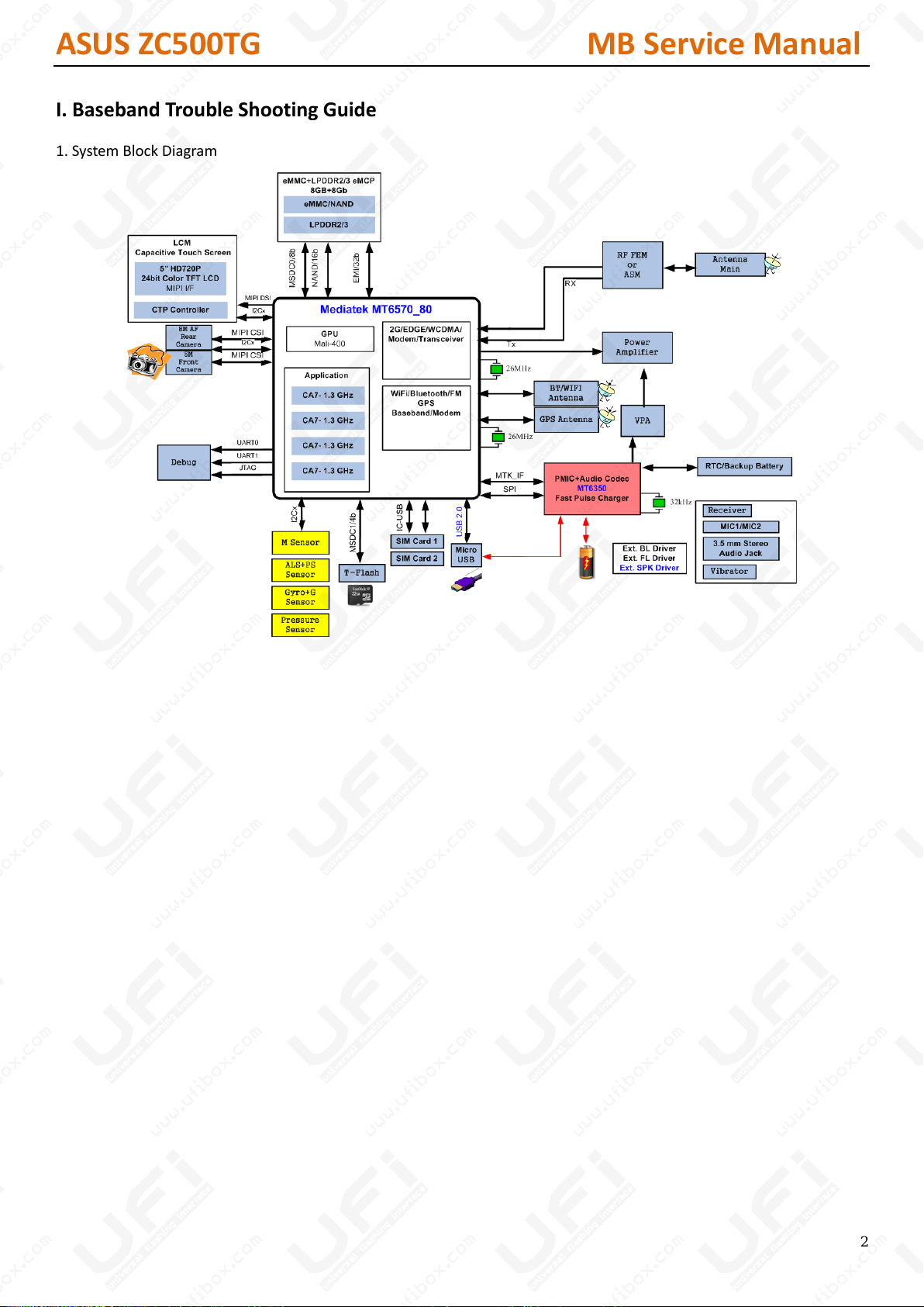
I. Baseband Trouble Shooting Guide
1. System Block Diagram
2
ASUS ZC500TG MB Service Manual
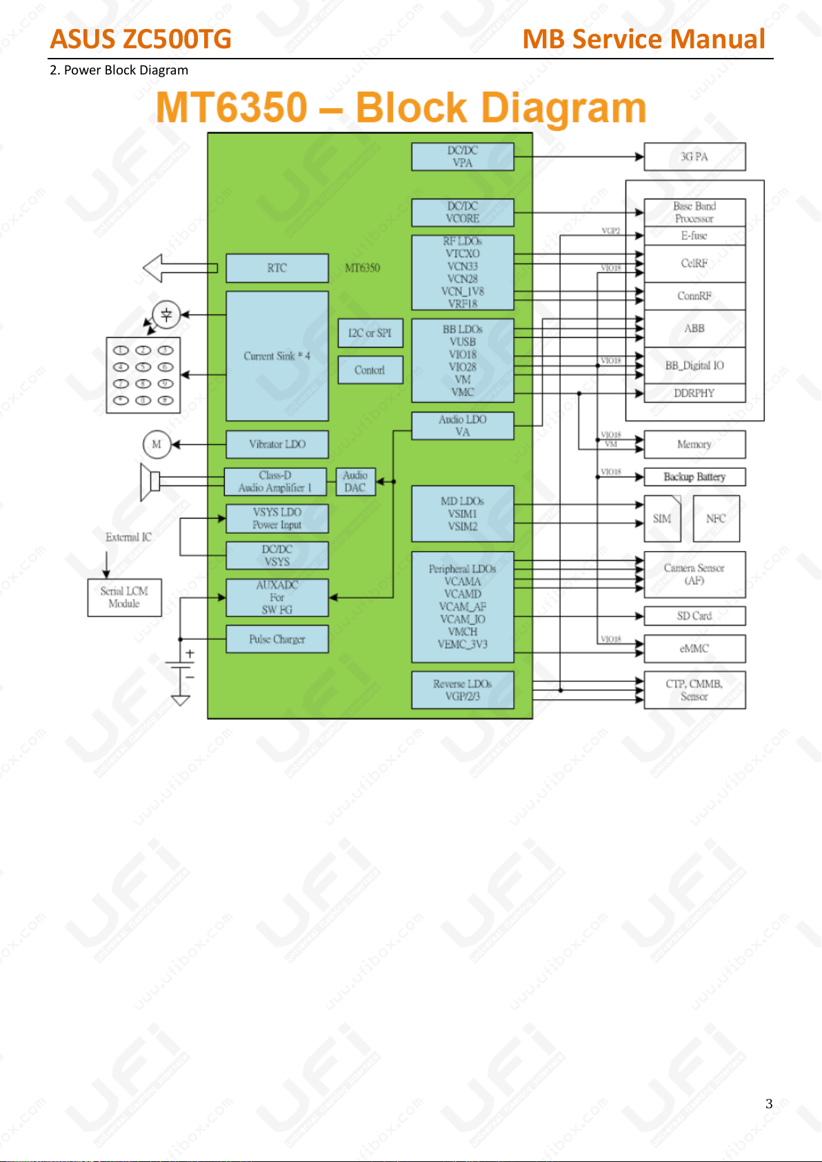
2. Power Block Diagram
3
ASUS ZC500TG MB Service Manual
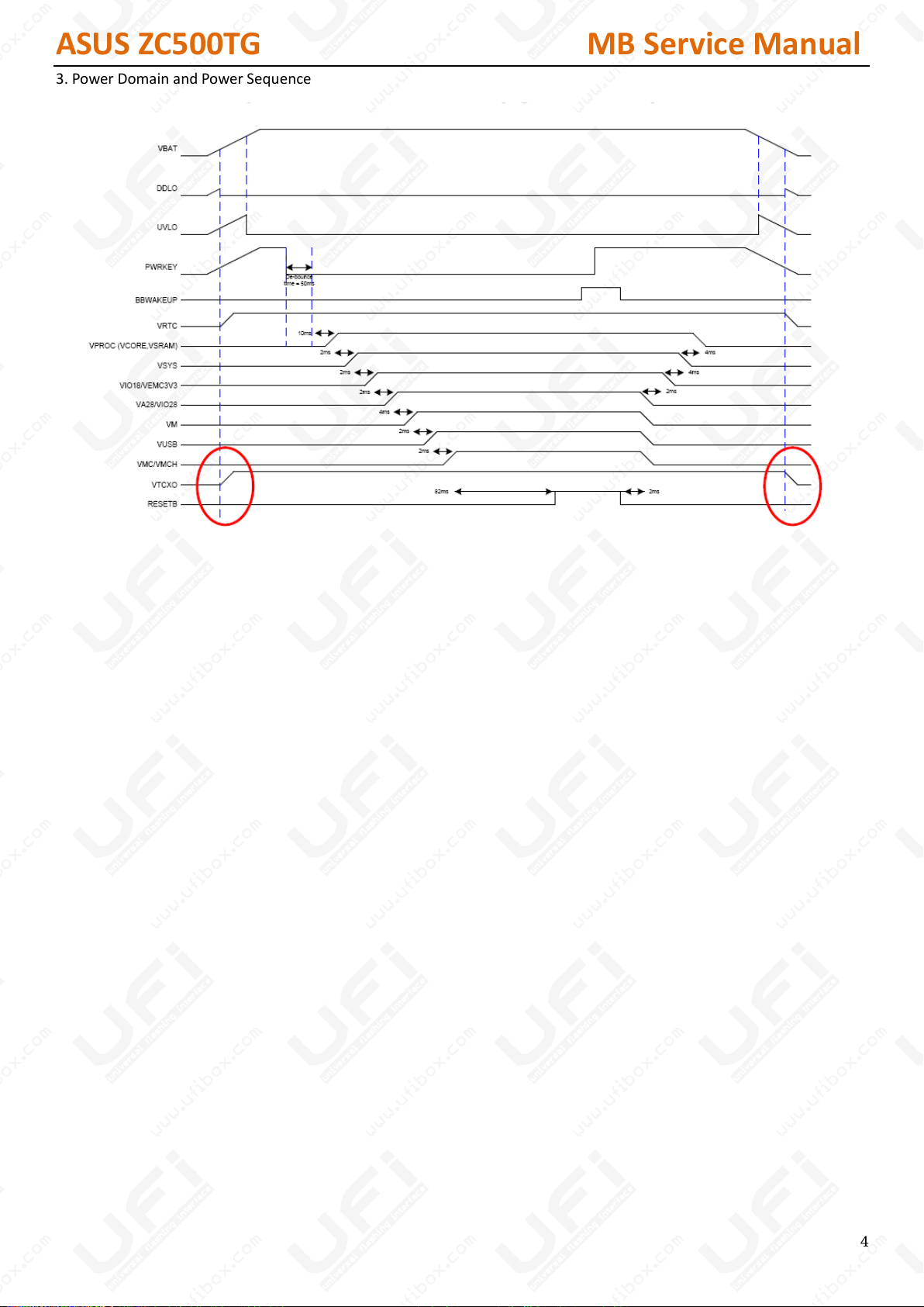
3. Power Domain and Power Sequence
4
ASUS ZC500TG MB Service Manual
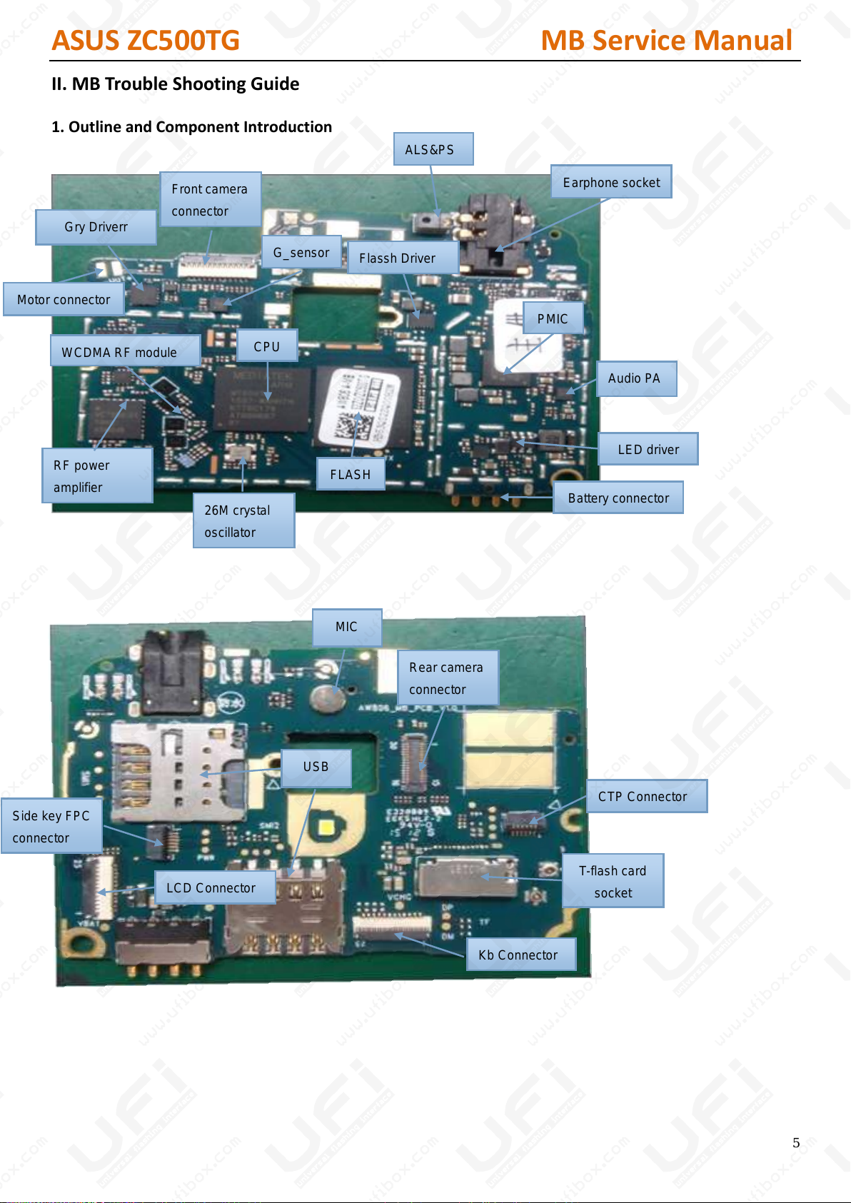
Gry Driverr
Front camera
connector
RF power
amplifier
WCDMA RF module
Rear camera
connector
Side key FPC
connector
26M crystal
oscillator
Battery connector
PMIC
Audio PA
CPU
FLASH
LED driver
CTP Connector
T-flash card
socket
Flassh Driver
Motor connector
USB
MIC
Kb Connector
Earphone socket
LCD Connector
ALS&PS
G_sensor
II. MB Trouble Shooting Guide
1. Outline and Component Introduction
5
ASUS ZC500TG MB Service Manual
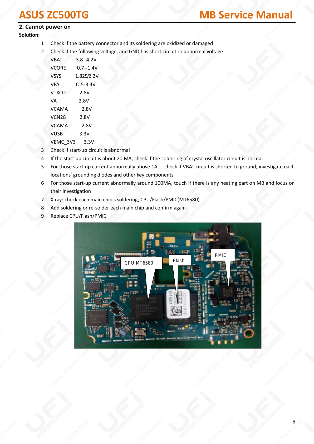
CPU MT6580
Flash
PMIC
2. Cannot power on
Solution:
1 Check if the battery connector and its soldering are oxidized or damaged
2 Check if the following voltage, and GND has short circuit or abnormal voltage
VBAT 3.8--4.2V
VCORE 0.7--1.4V
VSYS 1.825/2.2V
VPA O.5-3.4V
VTXCO 2.8V
VA 2.8V
VCAMA 2.8V
VCN28 2.8V
VCAMA 2.8V
VUSB 3.3V
VEMC_3V3 3.3V
3 Check if start-up circuit is abnormal
4 If the start-up circuit is about 20 MA, check if the soldering of crystal oscillator circuit is normal
5 For those start-up current abnormally above 1A, check if VBAT circuit is shorted to ground, investigate each
locations’ grounding diodes and other key components
6 For those start-up current abnormally around 100MA, touch if there is any heating part on MB and focus on
their investigation
7 X-ray: check each main chip’s soldering, CPU/Flash/PMIC(MT6580)
8 Add soldering or re-solder each main chip and confirm again
9 Replace CPU/Flash/PMIC
6
ASUS ZC500TG MB Service Manual
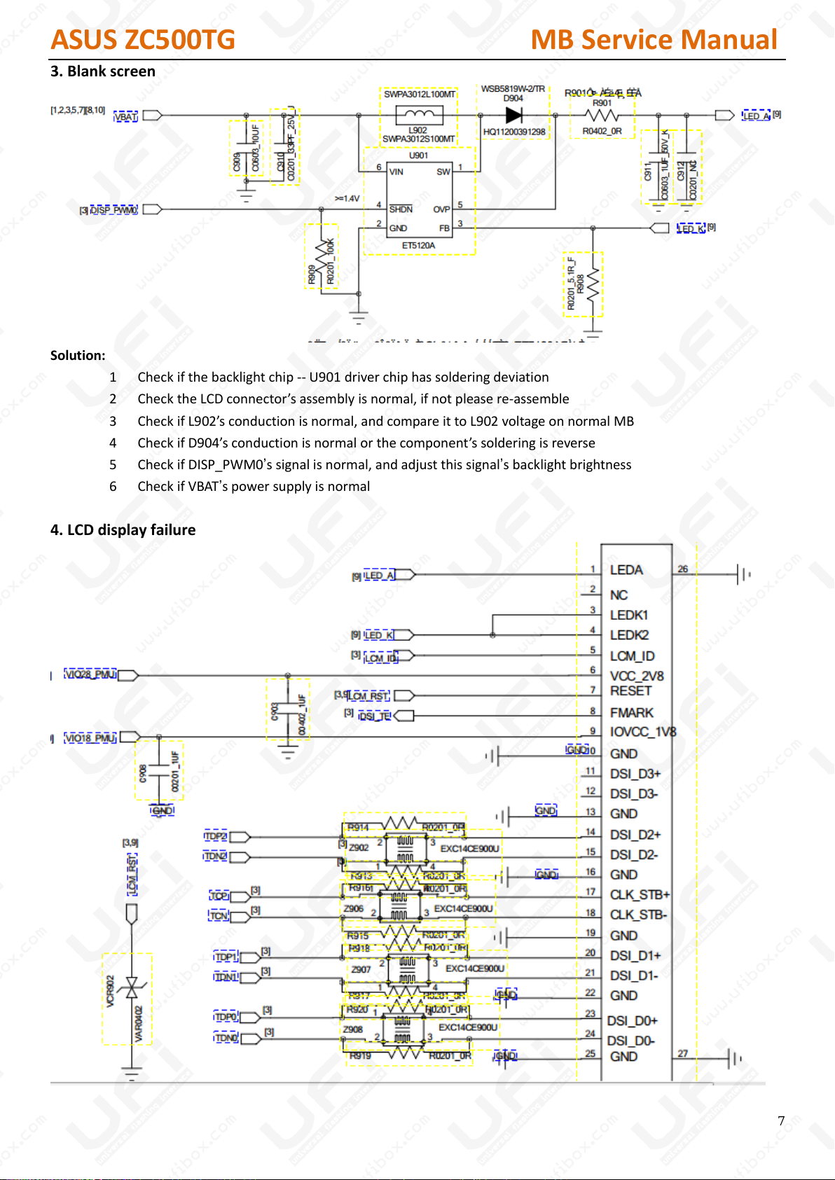
3. Blank screen
Solution:
1 Check if the backlight chip -- U901 driver chip has soldering deviation
2 Check the LCD connector’s assembly is normal, if not please re-assemble
3 Check if L902’s conduction is normal, and compare it to L902 voltage on normal MB
4 Check if D904’s conduction is normal or the component’s soldering is reverse
5 Check if DISP_PWM0’s signal is normal, and adjust this signal’s backlight brightness
6 Check if VBAT’s power supply is normal
4. LCD display failure
7
ASUS ZC500TG MB Service Manual
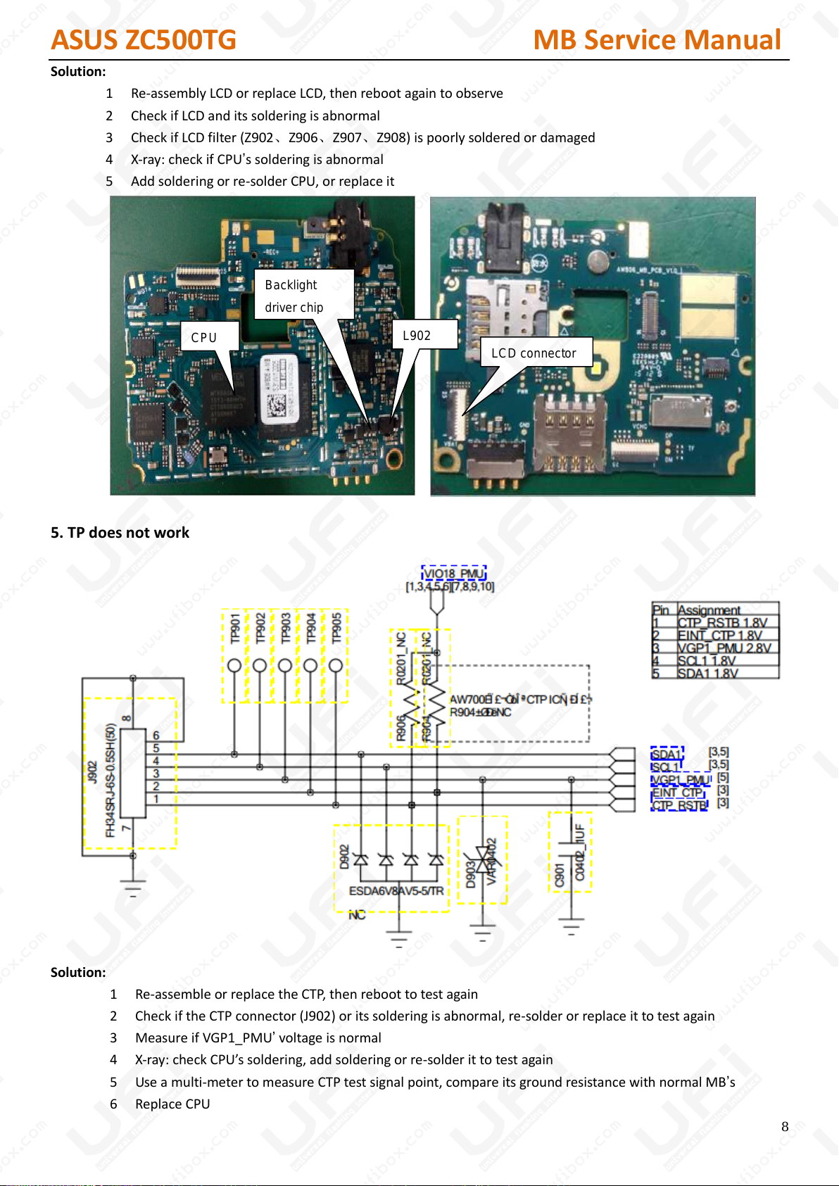
Backlight
driver chip
L902
CPU
LCD connector
Solution:
1 Re-assembly LCD or replace LCD, then reboot again to observe
2 Check if LCD and its soldering is abnormal
3 Check if LCD filter (Z902、Z906、Z907、Z908) is poorly soldered or damaged
4 X-ray: check if CPU’s soldering is abnormal
5 Add soldering or re-solder CPU, or replace it
5. TP does not work
Solution:
1 Re-assemble or replace the CTP, then reboot to test again
2 Check if the CTP connector (J902) or its soldering is abnormal, re-solder or replace it to test again
3 Measure if VGP1_PMU’ voltage is normal
4 X-ray: check CPU’s soldering, add soldering or re-solder it to test again
5 Use a multi-meter to measure CTP test signal point, compare its ground resistance with normal MB’s
6 Replace CPU
8
 Loading...